COMPUTATIONAL SIMULATION OFEM ATTENUATION BY PLASMAS
FORMED IN HYPERVELOCITYATMOSPHERIC FLIGHT
Michael J. Nusca* and Gene R. Cooper**
U.S. Army Research LaboratoryAberdeen Proving Ground, MD, 21005
Abstract
The attenuation of an electromagnetic wave propagat-ing through the hypervelocity flow field generated by anaerodynamic vehicle, is numerically investigated. Thereacting flow field consisting of nitric oxide ions, freeelectrons, and other species is simulated using compu-tational fluid dynamics. The Navier-Stokes equations,including a nonequilibrium air kinetics model consist-ing of seven species and twenty-six reactions, are solved.An electromagnetic wave, originating from within thevehicle, is attenuated by the free electrons (plasma) inthe chemically reacting flow. Attenuation analysis isperformed separately (uncoupled) from the gasdynamicanalysis using a series solution of Maxwell's equationsvalid for a long- wavelength plane wave and a thin (i.e., incomparison to wavelength) inhomogeneous plasma layer.The magnetic field, generated by the moving electronsin the plasma, is included in the analysis. The resultsof this study demonstrate that significant signal attenu-ation can occur for even weakly ionized air flows.
Cc
cv
EEeehi
Nomenclature
concentrationspeed of lightmass fraction of speciesspecific heat capacity, constant pspecific heat capacity, constant volumediffusion coefficient, species i into jdiffusion coefficient, species i into mixtureEckert number, V^/h^electric field strength (also E)electron chargespecific total internal energymolar specific enthalpy
* Aerospace Engineer, Associate Fellow AIAA;** Research Physicist, Member AIAA. Weapons& Materials Research Dir., Ballistics &; WeaponsConcepts Div. This paper is declared a work of theU.S. Government and is not subject to copyrightprotection in the United States.
k Boltzmann's constantkf, kb forward, backward reaction rates (Eq. 14)kT thermal diffusion ratio, Dx/DimL reference lengthLe Lewis number, Pr/ScM Mach numberM. molecular weightm massN total number of speciesUi number density of species ip static pressurePr Prandtl number, MooCp^/^oo3?i species i gas constant, it/'Miyt universal gas constantRe Reynolds Number,Sc Schmidt Number,T transmission coefficientT temperaturet timeu axial velocity componentV magnitude of the velocity vectorv radial velocity componentW EM power (amplitude)w chemical production term (Eq. 13)X mole fractionx, y cartesian coordinatesa 0 for 2D, 1 for axisymmetric flow(3 27r8/\r kTA.7 ratio of specific heats, Cp/c^AHf enthalpy of formationS plasma layer thickness£ magnetic permittivityK thermal conductivityA /iLe/RePrA EM wavelength, 2irc/u>fj. molecular viscosity or magnetic permeability/x0 reference magnetic permeability (4-7r/i)v stoichiometric coefficient for reactantsv stoichiometric coefficient for products£ electric conductivityp density(Tij collision diameter, species i with j(Txx normal stress tensor(j+ axisymmetric stress tensorTxy shear stress tensor4> collision frequencyw EM angular frequency (2?rx frequency)
in incidentm mixturen neutral speciesR reflectedT thermal or transmittedx, y coordinates derivativesoo freestream quantity
Introduction
Hypervelocity flight of aerodynamic and reentry ve-hicles in the atmosphere causes the chemical dissocia-tion of air in the shock layer surrounding the vehicle.This dissociation generates ions and electrons in the flowthat can shroud the vehicle in a thin, highly stratifiedlayer of plasma. Communications and telemetry signals,transmitted to and from these vehicles must propagatethrough a plasma layer and thus are subject to vary-ing degrees of attenuation. The use of a computationalfluid dynamics (CFD) approach to determine the prop-erties of the plasma, and an analysis of the resultingelectromagnetic (EM) wave attenuation, is investigatedin the present study. The gasdynamics analysis is basedon the Navier-Stokes equations. The analysis of EMwave attenuation is based on the plane-wave specializa-tion of Maxwell's equations represented by a series so-lution. This solution is simplified by assuming a thinplasma layer and a long-wavelength wave. In addition,the magnetic field, generated by the moving electrons inthe plasma, is included in the analysis. A specific con-figuration is considered consisting of an axisymmetricblunted cone-cylinder vehicle forebody (NASA-RAMC)that resembles missile and projectile planforms.
Previous Work
Previous theoretical studies of electromagnetic (EM)wave attenuation have treated the plasma layer as multi-ple layers of stacked dielectric material where each layeris of a certain fractional thickness of the total plasmalayer thickness, and each layer has a specified electro-magnetic permittivity constant [1-5]. The goal of theseefforts was to approximate both the stratification andoverall permittivity of the plasma in order to study waveattenuation. General conclusions from these studies arethat the reflection and transmission of EM waves at nor-mal incidence on a layer of ionized gas depend stronglyon both the thickness of the plasma layer and the de-tailed profile of the electron distribution. These studieswere reviewed by Nusca [6].
Boyer [7] conducted experimental studies using ashock tunnel of EM transmission through a hyperveloc-ity plasma generated about a blunt wedge or cone. TheEM transmission originated from a rectangular open-
ended waveguide (i.e., antenna) on the body surface andsignal attenuation was measured at selected locations inthe antenna/model far field using receiving antennas out-side the shock tunnel walls. The experiments where con-ducted in the Cornell Aeronautical Laboratory 96-inchHigh-Energy Shock Tunnel with a specially designed low-reflectance EM test section and freestream conditions ofabout 5000m/s velocity at an equivalent density altitudeof about 48km. The EM experiments where performedat frequencies from 1 to 4 GHz. A computational analy-sis of these data was conducted by Nusca [6].
The Physical Problem
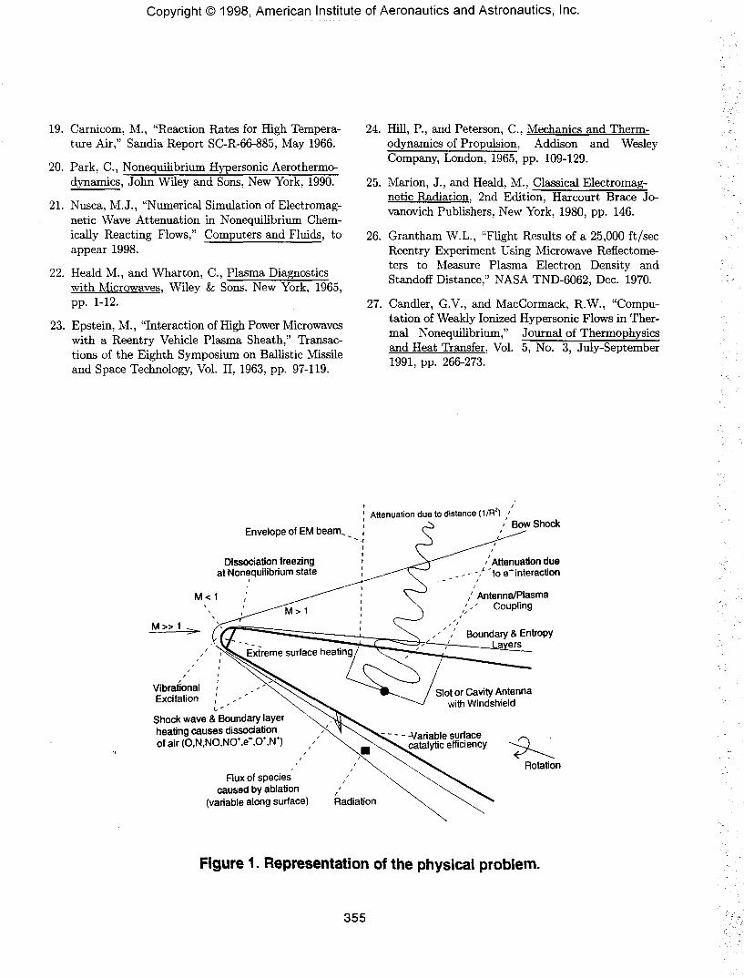
Consider a body of revolution (e.g., a missile) travelingat high velocity (i.e., 4-6 km/s) in the atmosphere with atrajectory that traverses moderate to high altitudes (40-60 km). Figure 1 shows a representation of the flow fieldaround the forebody of this vehicle with several phys-ical effects highlighted including: the shock layer, theentropy layer, the boundary layer, chemical equilibriumin the stagnation region, flow expansion onto the coni-cal forebody causing chemical "freezing" of ionization ata nonequilibrium state, surface enhancement of chemi-cal reactions, ablation introducing additional chemicalspecies and free electrons into the reacting gas as well asa static charge on the surface that can be strong enoughto interact with free electrons and ions in the gas (i.e.,charge separation and forced diffusion effects).
Now consider an antenna within the body surface (seeFigure 1). The antenna transmits EM radiation in theform of a microwave signal for purposes of communica-tion, sensing, or telemetry through a layer of ionized gasof variable thickness along the antenna aperture. The in-teraction of EM radiation with the ionized gas flow fieldcauses several effects: the signal propagation path is al-tered and a signal phase shift occurs (refraction causesthe wave propagation speed to change), a loss in signalstrength occurs due to attenuation (power or energy losschanges the intensity of the wave), and the antenna freespace radiation pattern and admittance properties aremodified [4,5]. The ionized gas layer represents a strat-ified medium or a medium of varying elasticity. Thespeed of each wave component is different for each fre-quency (or wavelength) in the medium; the medium issaid to be dispersive and the wave is refracted by themedium (i.e., phase shift). If the frequency of the har-monic EM wave is similar to the frequency of the elec-trons, the electrons will absorb energy from the wave.Since this energy is related to the frequency of the wave,this frequency will change. The amplitude (proportionalto the intensity) of the wave will decrease as it travelsthrough the medium and the wave is said to be atten-
uated. All of these effects may be expected to occursimultaneously, and are dependent upon the propertiesof the gas.
The Model Problem
In order to initiate the investigation of the physicalproblem, outlined above and shown schematically in Fig-ure 1, a model problem is constructed. This modelproblem, termed plane-wave/plasma-slab representsa special case of the physical problem and be used as thebasis upon which to construct an initial understandingof the physics of aerodynamic plasmas. A basic assump-tion for the model problem is that the ionized layer ofair, that shrouds the vehicle, is a plasma. A plasma isdenned as a macroscopically neutral ionized gas consist-ing principally of free electrons, free ions, and neutralatoms or molecules [8]. The dissociated air flow fieldis assumed to be electrically neutral as a consequenceof the chemical kinetics mechanism; for each NO+ ionproduced/consumed in the flow an electron is also pro-duced/consumed and therefore, the overall number den-sity of ions will be the same as that of electrons.
The vehicle is considered to be at a zero-yaw atti-tude so that the bow shock is symmetric about the body.The vehicle is not rotating. The flow field is consideredsteady. The freestream Mach number, pressure, anddensity are assumed to be such that gas temperaturesin the shock layer are below 9000K; for these tempera-tures, the effects of oxygen and nitrogen ionization (i.e.,N+ and O+) and gas radiation can be ignored. The an-tenna is considered to be locating on the vehicle forebodyfar enough downstream of the nosetip that vibrationalnonequilibrium effects are negligible. The surface of thevehicle is considered to be non-ablative and electricallyneutral (i.e., no static charge or EM properties) and isassumed to be either non-catalytic or fully-catalytic overthe entire length. The surface is assumed to be eitheradiabatic or isothermal.
The transmitting antenna is considered to be withinthe ground plane or surface of the vehicle (see Fig. 2)and the actual geometry and type of antenna is not con-.sidered. The transmitted wavefront is, in general, of acomplicated shape and the wave propagates radially inthree directions. For the present study, the EM wave isassumed planar (plane-wave) at the point of origin aswell as throughout its travel through the plasma, andharmonic with an amplitude (power), W, and angularfrequency, cu, with the waveform E = Wexp(iuit) and awavelength, A = 2-Trc/w.
For aerodynamically-generated plasmas it can beshown that the plasma layer is thin (relative to A), canbe considered of constant thickness, 6, locally (see Fig-
ure 2), and is weakly ionized (i.e., ratio of nei to neutralspecies number density is very small). The importantcharacteristics are ne\, collision frequency, <p, and elec-tron temperature, Tei, which can be described by pro-files that are functions of distance along the y-direction(plasma-slab). Since the plasma layer is thin, the timeinterval of interaction between the wave and the plasmais very short. The electrons are disturbed in an oscil-latory manner by this interaction but, this oscillatorymotion is about unaltered electron trajectories throughthe plasma. The interaction of the EM wave and thefree electrons in this case is solely an exchange of en-ergy. The analysis presented in this investigation doesnot consider solution of the coupled Navier-Stokes andMaxwell equations.
Gasdynamics Analysis
The chemically reacting hypervelocity flow fieldaround a body is numerically simulated using computa-tional fluid dynamics. The ARL-NSRG2 code [6,9] solvesthe 2D/axisymmetric, unsteady, real-gas Navier-Stokesequations including equations for chemical kinetics anddiffusion. These partial differential equations are cast inconservation form and converted to algebraic equationsusing a finite-volume formulation. Solution takes placeon a mesh of nodes distributed in a zonal fashion aroundthe body and throughout the flow field such that sharpgeometric corners and other details are accurately rep-resented. The body region is represented by a blankedzone. The conservation law form of the equations as-sures that the end states of regions of discontinuity (e.g.,shocks) are physically correct even when smeared over afew computational cells.
The Navier-Stokes equations for 2D/axisymmetric re-acting and unsteady flow are written in the followingconservation form. All variables have been nondimen-sionalized in a conventional fashion [6,10].
The G array is similar to the F array but contains y-derivative terms [6]. Pick's law, including diffusion com-ponents due to concentration and thermal gradients (i.e.,Vci and VlnT, respectively) has been utilized in theabove. The thermal diffusion ratio, k?, can be computedusing semi-empirical formulations (see Reference 11 fordetails). The multicomponent diffusion coefficient, Dim,is given by Bird [12] relating the binary diffusion coef-ficient for species i diffusing into species j, Dij, to themulticomponent diffusion coefficient for species i diffus-ing into the mixture, Dim,
Dim = E, (2)
Solution of Boltzman's equation, and assuming an idealgas law, results in the expression [13],
0.00266T3/2(3)
1-1where Mij = 2{(l/Mi)+ (l/Mj)} is the combinedmolecular masses of species i and j, and OD is the col-lision integral for diffusion (<Tij in Angstroms, D^ incm2/s, T in K, and p in bar). Rules used to obtainthe interaction value CTJJ from CTJ and Oj as well as ODwhich is related to the characteristic Lennard-Jones en-ergy, are given by Reid [13]. Equation 3 is formally notapplicable to electron diffusion since the collision crosssection and the characteristic Lennard-Jones energy arezero for the electron. However, the diffusion of ions andelectrons is linked because of the induced electric fieldwhich will occur if an electron concentration gradient iscaused by electron/ion redistribution, i.e., charge sepa-ration [14]. In a partially ionized gas with zero electric
current, when no charge separation occurs, the diffusionvelocity of electrons is equal to the diffusion velocity ofions; the diffusion coefficient for the electrons is then de-termined using that of the ions. The gas is thus renderedlocally neutral.
The following state equations are used,
(4)
e =' 1=1
N N
(5)
(6)1=1The ratio of specific heats is given by 7 — cp/cv, where,
(cv is similarly defined). The following fourth-orderpolynomial curve fits with coefficients A — E [15] is used,
cpi =Ai + + + (8)
with cVi = cp.L — 3?. The species viscosity and thermalconductivity are also determined from curve-fit data (seeRef. 16 for coefficients A — E),
(9)Hi = [exp (C)} T^Aln
«4 = [exp (E)] rN'-^+Bd
The mixture viscosity and thermal conductivity are de-termined using Wilke's law denoting / as p, or K,
N
(11)
Chemical reactions can be expressed in a general re-action equation given by (Xi represents the symbol forspecies i),
(Ef is the dissociation energy), while the backwardrates are obtained from the equilibrium constant, Keq =kf/kb. Entropy, S, and enthalpy, h, are computed usingcurve-fits [15], and then for each reaction,
(15)
— gproducts — greactantS) g = h — TS
The present study includes seven species (C>2, N2,O,N,NO,NO+, and e~) and twenty-six reactions (seeRef. 6). Data for C/,r]f and E/ are given by Dunn[17], Lin [18], Carnicom [19], and Park [20].
The integral form of the conservation equations (Eq.1) is convenient for the finite-volume solution scheme.
-I- / / Udxdy + f (Fdy - Gdx) + f f Hdxdy = 0°t Jn J JAQ. Jn J
(16)where, Jl is the region or computational cell, and dQ isthe boundary or the cell sides. See References 6 and 9for further details on the numerical solution of Eq. 16.
Body surface boundary conditions considered includeadiabatic (i.e., zero wall heat transfer) and non-catalyticassumptions. See Reference 6 for results using isother-mal and fully-catalytic boundary conditions.
Validation
The CFD code has been validated using a varietyof test cases. In particular a test case for chemicallyreacting flows involves the low density hypervelocity(Moo =25.3) flow over a sharp wedge of 10 degrees half-angle and about one-meter in length. A test case forelectron production in reacting flows involves the low-density hypervelocity (Moo=9.3) flow over a blunt coneof 7.8 degrees half-angle, .043-meter nose radius, andabout one-meter in length. Computational results (i.e.,species mass fraction profiles, including electrons, sur-face pressure and heat transfer) compared to these testcases is given in Reference 21.
Electromagnetics Analysis
The ionized gas layer about a hypervelocity vehicle canbe treated as a plasma if the layer consists of an equalnumber of electrons and ions mixed with neutral parti-cles. A numerical study conducted by Shen [14] showedthat the nonequilibrium air shock layer about a hyperve-locity vehicle is grossly electric neutral, since a slight sep-aration of charges induces a strong electric field that pre-vents the charges from separating further. An estimate
of the order of magnitude of the minimum distance overwhich the gas mixture of temperature, T, can be consid-ered a plasma is given by [24] £ = [(9£kT)/(e2nei)]1/2.The permittivity of gas, e, is usually very close to thatin free space. The charge density is ene\. Except fora numerical factor (i/9), this distance, £, is the classicDebye length. In this investigation it is assumed thatthe Debye length (typically .007mm) is much smallerthan the shock layer thickness (typically .5cm). Aero-dynamic plasmas tend to be weakly ionized [24] so that,ne\/(nn — nei) < 10~4. The number density of electronsin a weakly ionized plasma must be much smaller thanthat of the neutral species, nn, and collisions betweenelectrons and neutral particles very much more frequentthan collisions between electrons and ions (e.g., NO+).
Maxwell's equations describe the space-time variationof the EM field. It is assumed that the EM wave con-sists of an electric field (E) only so that the magneticfield (S) can be ignored (see "Extensions to the EMModel" for magnetic field considerations). The E fieldsatisfies a wave equation which contains damping termsproportional to the conductivity (£) of the medium [25].
--at
d2E' dt2 (17)
In order to solve this equation the following assump-tions are made: 1) the plasma layer is confined to theshock layer along the surface of a high speed vehicle; 2)the plasma layer thickness, S, is constant near the pointwhere the E wave transverses the plasma (i.e., near thevehicle transmitter) and plasma properties vary only inthe surface-normal direction, y; 3) the E wave is a planewave incident normal to the plasma layer boundary orplasma/vehicle interface. Then,
dE_dt
d2Edt2 (18)
where £ is the complex electric conductivity of theplasma, £ = neie2/me\(4> + i(J). The quantities E, fj,, ne\,and (j> are functions of y. The electric field strength isalso a function of time and can be assumed to havea waveform corresponding to harmonic motion, E =E0 exp(zwi). The second assumption precludes analy-sis of the flow stagnation region at the body nosetip, theexpansion region from the nosetip onto the body surface,and the wake flow. In each of these regions the distrib-ution of electrons may be significantly two-dimensional.Away from these regions the ne\ profile changes slowlyalong the body.
Epstein [23] developed a solution for Equation 18employing an infinite series and using the assumptionsstated above. The series was approximated using the
first two terms, assuming that the layer is sufficientlythin (i.e., S/X is small). As a result of Epstein's analy-sis the transmission coefficient, T, is computed from theproperties of the plasma layer using simple algebraic ex-pressions based on /j, (permeability). A balance of powerfor the interaction of the EM wave with the plasma layercan be written as (see Figure 2): the power transmittedthrough the plasma is equivalent to the power incidenton the plasma, minus the power absorbed by the plasma,minus the power reflected by the plasma layer. This bal-ance can be written in non-dimensional equation formas,
w-m- win w-mThe ratio of the transmitted power to the incident signalpower can be expressed in terms of the product of Tand the complex conjugate, T, as shown in Equation 19.Expressed in terms of decibels of attenuation,
dB = ioioglo 0|̂ = -ioioglo (TT) (20)Here WT < W-m but dB is generally expressed as a pos-itive number. Details concerning the formulation of thetransmission coefficient are given in References 6 and 21.
TT = + 2(32A2C2 (21)
where C = 2 + /3B (/? = 27r<5/A) with A and B computedusing integrals of the electron number density, nei, andcollision frequency, </>, distributions across the plasmalayer [6,21]. These constitutive parameters of the plasma(i.e., nei and <p) are determined using the gasdynamicscode.
This EM analysis method has been validated usingmeasured attenuation of signals with frequencies from1.5 to 17 GHz resulting from signal passage through theplume of a stationary plasma thruster (SPT). Computa-tional results using the present EM code and comparedto these test data and an independent ray-tracing analy-sis are discussed in References 6 and 21.
Validation of the Overall Method
Boyer [7] conducted experimental studies using ashock tunnel of EM transmission through a hyperveloc-ity plasma generated about a blunt 20-degree half-anglewedge of about 48cm in length (see discussion in "Pre-vious Work"). Nusca [6,21] presents a detailed compu-tational fluid dynamic analysis of the Boyer experiment;summarized in Tables 1 and 2. The inclusion of vis-cous transport phenomena proved to be a major factor inachieving good comparison between measured and com-puted signal attenuation. Laminar flow predictions of
electron distribution in the shock/boundary layer weremuch larger that those for inviscid simulations, whichhad a direct effect on signal attenuation. Variable Lewisnumber was found to have a small effect on the pre-dicted signal attenuation; the distribution of electronsin the shock layer was increased slightly near the wallfor constant (i.e., Le=l and 1.4) as compared to variablemass diffusion. The adiabatic wall condition yielded thegreatest number of electrons at the wedge surface whichin turn produced the largest degree of signal attenuation.Computations performed using a fully-catalytic wall as-sumption showed a reduction in electron number densitynear the wall, caused by electron-ion recombination, anda resultant drop in signal attenuation.
Table 1. Signal Attenuation (dB) ResultsCase No.
(see Table 2)123456
Experiment [7]
Signal Frequency (GHz)1.710.716.616.616.516.015.818
2.69.215.415.415.314.714.317
4.03.96.86.86.66.05.78
No.123456
Table 2. CasesDescription
Inviscid, Adiabatic WallViscous, Adiabatic Wall, Le = 1
Viscous, Adiabatic Wall, Le = 1.4Viscous, Adiabatic Wall, Variable Le
Viscous, Cold Wall, Variable LeViscous, Catal. Cold Wall, Variable Le
Results
In-flight measurements of shock layer ionization for areentry body travelling at hypervelocity were obtained inthe 1970's as part of the NASA Langley Research Cen-ter's Project RAM (Radio Attenuation Measurements).Electrostatic probes projecting from the vehicle into theair plasma layer were used to measure electron-densitydistributions. On-board diagnostic and VHP antennasas well as reflectometers were used to obtain information,such as peak electron number density, within the sur-rounding plasma. Detailed information on these flightsis available from several references [17,26].
The RAM-C flight vehicle consists of a 15.24 cm radiushemispherical nose followed by a 9 degree half-angle cone135 cm in length (total body length of 150 cm). The nose
was covered by a beryllium cap heat sink during the por-tion of the flight trajectory when high-altitude data wasobtained. The cone was made of phenolic-graphite char-ring ablator for heat protection. The vehicle velocity wasrecorded to be about 7.65 km/s over an altitude rangeof 61 to 81 km. Microwave reflectometers were used tomeasure the peak values of electron number density inthe shock layer at one location on the nosecap and threelocations along the cone (13.7, 18.2, 79.0, 116.3 cm fromthe nosetip of the vehicle). A Langmuir probe rake thatextended across the shock layer at the base of the conewas used to measure electron number density profiles.Detailed descriptions of the reflectometer and the probeas well as data reduction procedures are given elsewhere[26].
The RAM-C test case has been used by several re-searchers for the purpose of code validation and calibra-tion [17,27]. Typical flight conditions chosen correspondto an altitude of 71 km: 4.521 N/m2 (.000044 atm) pres-sure, 217 K temperature, and .000072 kg/m3 density.The freestream velocity of 7650 m/s corresponds to afrozen flow Mach number of 25.9 and a Reynolds num-ber of .41 million per meter. For the present numericalsimulation radiation energy exchange is neglected andviscosity is modeled as laminar with Le=1.4, constant.The flow is assumed to be in thermal equilibrium. Thecomputational grid selected, consisting of 200 axial and150 radial cells including clustering near the cone surface.The nosecap region contains 50 grid cells distributed un-evenly in an azimuthal pattern. The computational gridis extended one nosecap radius (i.e., 7.62 cm) upstreamof the body and 4 radii (i.e., 30.5 cm) above the bodycenterline. No-slip and no-penetration boundary condi-tions as well as a constant wall temperature of 1000K areapplied along the grid line defining the nosecap and conesurface. The cone wall is assumed to be non-catalytic sothat the normal gradients of all species mass fractionsare set to zero.
Figure 3 shows the computed density contours overthe nosecap and cone surface. The vehicle is shown inwhite. The detached bow shock and associated high gasdensity is evident as is the rapid expansion over the nose-cap and onto the cone surface. The variation of densityin the shock layer is caused by streamlines that havepassed through sections of the bow shock with variablecurvature. Figure 4 shows the computed electron num-ber density contours (/cm3). The shock layer is essen-tially a stratified inhomogeneous plasma layer with thegreatest electron density values found near the surface.
The RAM-C flight test program yielded measured re-sults for peak electron number density in the shock layerusing reflectometers mounted at four locations along thevehicle surface. Reflectometers use microwaves, beamed
into the shock layer and reflected by electrons in the flow.Calibration for the degree of reflection of microwaves al-lows the determination of the peak electron number den-sity [26]. Figure 5 shows the distribution of peak (i.e.,maximum) electron number density in the shock layeralong the RAM-C vehicle as measured by reflectometersand as computed by Dunn and Kang [17] and Candler[27] as well as the present author. Candler's computa-tional method is similar to that used here except thatthermal nonequilibrium is assumed. Dunn and Kangemploy a viscous shock layer (VSL) method that uses atwo-layer model of the thin shock layer and boundarylayer on the body. The general trends for computationsfollow that of the data - higher densities at the nose-cap with lower densities corresponding to flow expansionover the cone. The present results show a smaller den-sity than measured at the first data station which is alsowhere the grid cell aspect ratios change abruptly, butadequately capture reduction in density over the cone.
Computations of plane-wave transmission coefficientswere carried out by Dunn and Kang [17] for the RAM-Cvehicle. Values of 105 dB for signal frequencies of 0.1 to2.2 GHz and 3 dB for 10 GHz, at a position of about1.2 nosecap radii from the leading edge of the vehicleand at a vehicle altitude of 71 km, were reported. Thepresent analysis yields values of 102 dB (0.1-2.2 GHz)and 2.8 dB (10 GHz) for the same conditions. Note thatattenuation is reduced at higher frequencies, consistentwith the results shown in Table 1. Differences in values(between Dunn and the present author) may be due tochanges in the properties of the plasma layer as deter-mined by different gasdynamic codes. Further computa-tions and comparisons for various vehicle altitudes willbe reported.
Conclusions
A combined gasdynamic and electromagnetic methodof computing the weakly ionized plasma layer over a hy-pervelocity vehicle in the atmosphere has been described.Low density shock tunnel data for a blunt wedge as wellas high altitude flight test data for NASA's RAM-C ve-hicle has been used as means of testing the analysis.Future computations will be aimed at exploring plasmaattenuation for hypervelocity flight at various altitudesand seeking a means of reducing this effect.
Extensions to the EM Model
Maxwell's equation for E (Eq. 18) can be solved alongwith the Navier-Stokes equations (Eq. 1), where cou-pling is through the plasma layer electron number den-sity, nei, and the collision frequency, <p. Coupling termscan be used in the gas dynamic momentum equations,
QE + j x B, and the energy equation, E • J. The excesscharge in a plasma, Q, is negligible, and in the presentanalysis, the magnetic field, j x B, is not considered;then QE + j x B = 0. The current that induces the Bfield, J, was ignored as well, and E • J = 0.
The current in the plasma may not always be ignoredespecially when the electrons take on a cyclotron mo-tion (as well as a harmonic oscillations) due to the in-teraction with the EM wave (E and B fields). Onlythe E field and the oscillatory electron motion was in-cluded in the present study. The cyclotron motion ofthe electrons induces a weak magnetic field, B0, as well.Modification of the present EM analysis method to in-clude B0 can take the form of a modified electric con-ductivity of the plasma (see Eq. 18 and following),£ = neie2E0/me-[((/) + i(u + wc)), which now includes theamplitude of the electric field, E0, and the cyclotron fre-quency, u>c — eB0/me\c. Modification of £ results inmodifications to the terms A and B for Equation 21,and thus a modification of the transmission coefficient.Results using these modifications to the EM analysismethod will be reported in future papers.
Acknowledgments
This work was supported by the Army Research Lab-oratory and the DoD High Performance Computing Re-search Initiative (computer time on the WES C90 andthe NAVO C90).
References
1. Albini, F. and Jahn, R., "Reflection and Transmis-sion of Electromagnetic Waves at Electron DensityGradients," Journal of Applied Physics, Vol. 32,No. 1, Jan. 1991, pp. 75-82.
2. Gal, G., "Electromagnetic Wave Propagation in aLossy Plasma Slab with a Gradient Transverse tothe Incident Wave," NASA SP-252, 1971.
3. Click, H., "Interaction of Electromagnetic WavesWith Plasmas of Hypersonic Flows. ARS Journal.Vol. 32, Sept. 1962, pp. 1359-1364.
4. Galejs, J., "Admittance of a Waveguide Radiatinginto Stratified Plasma," IEEE Transactions onAntennas and Propagation, Vol. AP-13, No. 1,Jan. 1965, pp. 64-70.
5. Galejs, J., "Slot Antenna Impedence for PlasmaLayers," IEEE Transactions on Antennas andPropagation, Vol. AP-12, No. 6, Nov. 1964, pp.738-745.
7. Boyer, D., Bein, G., and Andre, S., "Studies of Mi-crowave Transmission Through A Hypersonic AirPlasma," Sandia Report SC-CR-67-2710, 1967.
8. Papas, C., Theory of Electromagnetic WavePropagation, Dover, New York, 1988.
9. Nusca, M.J., "Computational Simulation of theRam Accelerator Using a Coupled CFD/Interior-Ballistics Approach" AIAA Paper No. 97-2653.
10. Widhopf G.F., and Wang, J.C.T., "A TVD Finite-Volume Technique for Nonequilibrium ChemicallyReacting Flows," AIAA Paper 88-2711.
11. Chapman, S., and Cowling, T., The MathematicalTheory of Non-Uniform Gases, Cambridge Univer-sity Press, Cambridge, 1970, pp. 155, 165.
12. Bird, R., Stewart, W., and Lightfoot, E.,Transport Phenomena, Wiley & Sons, New York,1960, pp. 571.
13. Reid, R., Prausnitz, J., and Poling B., The Prop-erties of Gases and Liquids, 4th ed., McGraw-HillBook Company, New York, 1987), pp. 581-589.
14. Shen, J., and Qu, Z., "Numerical Study ofNon-Equilibrium Flowfield Coupled With ElectricField," AIAA Paper 95-6070.
15. Afeefy, H.Y., Liebman, J.F., and Stein, S.E., "Neu-tral Thermochemical Data" in NIST Standard Ref-erence Database Number 69, Eds. W.G. Mallardand P.J. Linstrom, Feb. 1997, National Instituteof Standards and Technology, Gaithersburg, MD,20899.
16. Gupta, R.N., Yos, J.M., Thompson, R.A., and Lee,K., "A Review of Reaction Rates and Thermody-namic and Transport Properties for an 11-SpeciesAir Model for Chemical and Thermal Nonequilib-rium Calculations to 30000K," NASA RP-1232, Au-gust 1990.
17. Dunn, M., and Kang, S.-K., "Theoretical and Ex-perimental Studies of Reentry Plasmas," NASACR-2232, April 1973.
18. Lin, S., and Teare, J., "A Streamtube Ap-proximation for Calculation of Reaction Rates inthe Inviscid Flow Field of Hypersonic Objects,"Transactions of the Sixth Symposium on BallisticMissile and Space Technology, Vol. IV, AcademicPress, New York, 1961, pp. 35-50.
19. Carnicom, M., "Reaction Rates for High Tempera-ture Air," Sandia Report SC-R-66-885, May 1966.
20. Park, C., Nonequilibrium Hypersonic Aerothermo-dynamics, John Wiley and Sons. New York, 1990.
21. Nusca, M.J., "Numerical Simulation of Electromag-netic Wave Attenuation in Nonequilibrium Chem-ically Reacting Flows," Computers and Fluids, toappear 1998.
22. Heald M., and Wharton, C., Plasma Diagnosticswith Microwaves. Wiley & Sons. New York, 1965,pp. 1-12.
23. Epstein, M., "Interaction of High Power Microwaveswith a Reentry Vehicle Plasma Sheath," Transac-tions of the Eighth Symposium on Ballistic Missileand Space Technology, Vol. II, 1963, pp. 97-119.
24. Hill, P., and Peterson, C., Mechanics and Therm-odynamics of Propulsion, Addison and WesleyCompany, London, 1965, pp. 109-129.
25. Marion, J., and Heald, M., Classical Electromag-netic Radiation. 2nd Edition, Harcourt Brace Jo-vanovich Publishers, New York, 1980, pp. 146.
26. Grantham W.L., "Flight Results of a 25,000 ft/secReentry Experiment Using Microwave Reflectome-ters to Measure Plasma Electron Density andStandoff Distance," NASA TND-6062, Dec. 1970.
27. Candler, G.V., and MacCormack, R.W., "Compu-tation of Weakly Ionized Hypersonic Flows in Ther-mal Nonequilibrium," Journal of Thermophysicsand Heat Transfer. Vol. 5, No. 3, July-September1991, pp. 266-273.
Attenuation due to distance (1/R2) >
Envelope of EM beanx _
Dissociation freezingat Nonequilibrium state
VibrationalExcitation
Shock wave & Boundary layerheating causes dissociationof air (O.N.NO.NO'.e-.CT.N*}
Bow Shock
/'Attenuation due_ . - - - / 'to e~interaction
/ Antenna/PlasmaCoupling
' ,' Boundary & Entropy.ayers
Slot or Cavity Antennawith Windshield
sT - - -Variable surface ~catalytic efficiency "̂ L
RotationFlux of species
caused by ablation /(variable along surface) Radiation