300
Automation Control Equipment Main Catalogue 2016 ACE: Your partner for industrial shock absorbers, gas springs and vibration control Damping Technology

Automation Control Equipment
Main Catalogue 2016
ACE: Your partner for industrial shock absorbers, gas springs and vibration control
Damping Technology

Print compensatedId-No. 1659495
www.bvdm-online.de
All rights to the production, trade names, design and illustrations of this catalogue are reserved. No part of this publication may be reproduced, copied or printed without permission; violations will be prosecuted. Construction, dimensions and specifi cations of ACE products are subject to change.
www.ace-ace.com
Complete Product RangeData Sheets & Catalogues
CAD DatabaseFree Calculation Programs
DistributorsServices
Newsetc.
1Is
sue
08.2
016
– Sp
ecifi
catio
ns s
ubje
ct to
cha
nge
ACE Stoßdämpfer GmbH . PO Box 1510 . D-40740 Langenfeld . T +49 (0)2173 - 9226-4100 . F +49 (0)2173 - 9226-89 . [email protected] . www.ace-ace.com
Dear customer,
In the last few years not only has the size of our company grown but also its product line. In addition to our own innovations that open new opportunities, complementary products to help fi nd solutions to the diverse market require-ments have also been included. It was time to sort out our range.
You will fi nd a new layout with the subdivision of the products according to their application areas – automation control, motion control, vibration control and safety products. Each segment is identifi ed by its own colour. The integrated concept can be found refl ected in all of the documents in the new demonstra-tion car, at our exhibition stand and on the new website www.ace-ace.com. Our website, the tool for professionals, also offers the ACE You Tube channel, an extensive CAD library as well as calculation assistance.
As usual, you will fi nd the news displayed in the table of contents and on the individual catalogue pages. You can get familiar with the new standard for industrial gas springs, the NEWTONLINE from our German production, for instance. It stands for a longer service life, improved running properties and more application possibilities through an extension force that is immediately available.
ACE products help you keep your production and processes faster, more effi cient, quieter, easier, safer and more sustainable. Expect ACE quality in the products and the 5 star service.
Your Jürgen Roland (Managing Director)
Free Service HotlineTell us about your requirements and take advantage of our more than 40 years of expert knowledge in damping technology. Our specialists in engineering discuss your requirements with you and demonstrate our possibilities. Take advantage of our service hotline T +49 (0)2173 - 9226-4100Also, our regional managers are genuine shock absorber specialists. They will visit you onsite, note down the fi eld data and work out customized solutions for you.Furthermore: ACE service support and products are available in more than 40 countries worldwide.
CAD Online Calculation ProgramWith our user-friendly calculation program in the internet you can select the right product – online or via download of the program. The CAD data is available in all standard formats in 2D and 3D.www.ace-ace.com Our specialist engineers create detailed technical solutions for you including assembly suggestions and details on machine loads, brake time and workload etc.
Preface
Automation Control Equipment
by ACE
S E R V I CE
2
Issu
e 08
.201
6 –
Spec
ifica
tions
sub
ject
to c
hang
e
ACE Stoßdämpfer GmbH . PO Box 1510 . D-40740 Langenfeld . T +49 (0)2173 - 9226-4100 . F +49 (0)2173 - 9226-89 . [email protected] . www.ace-ace.com
Certified Quality
ACE products are exclusively manufactured from high quality and environmentally com- patible materials. With permanent quality monitoring and the performance of test programs, a constant high quality can be guaranteed.
ACE pursues continual improvement in all areas in order to arrange material and energy consumption, the production of damaging substances and recycling or disposal of end products as gently on resources as possible.
It is important to us to keep the strain on the environment as low as possible and simultane-ously improve our services.
With ongoing optimisation of end products, we also give our customers the option of designing their products to be smaller, more effective and more energy-saving.
Automation Control
Motion Control
Vibration Control
Safety Products

3Is
sue
08.2
016
– Sp
ecifi
catio
ns s
ubje
ct to
cha
nge
ACE Stoßdämpfer GmbH . PO Box 1510 . D-40740 Langenfeld . T +49 (0)2173 - 9226-4100 . F +49 (0)2173 - 9226-89 . [email protected] . www.ace-ace.com
ACE is the world’s globally recognized specialist in the field of industrial damping technology – with agencies in 45 countries on all continents. ACE has also been represented in Germany since 1978. Here 25 engineers work every day on the further development of the product range.
We are your Specialists for Industrial Damping Technology
ACE customers benefit from sophisticated solutions, valuable innovations and exemplary service around the topic of damping technology. Through close cooperation with leading engineering companies, in particular the German ACE subsidiary has established itself as a pioneer in the field of technical progress in damping technology.
This catalogue is the decisive step to let the frequently expressed customer request come true: to supply everything for damping technology and vibration isolation from one single source.
ACE develops, produces and sells a wide range of damping products. It comprises industrial and safety shock absorbers, profile dampers, rotary dampers, industrial gas springs, hydraulic dampers, vibration isolators, air springs and hydraulic feed controls.
The products assert themselves particularly in future-oriented companies because there are virtually no better solutions to quickly, gently and precisely slow down moving masses or to isolate harmful vibrations.
Safety Shock Absorbers, Safety Dampers, Clamping Elements
Rubber-Metal Isolators, Vibration-Isolating Pads, Low Frequency Pneumatic Levelling Mounts
Industrial Gas Springs (push type), Industrial Gas Springs (pull type), Hydraulic Dampers, Hydraulic Feed Controls, Door Dampers, Rotary Dampers
Miniature Shock Absorbers, Industrial Shock Absorbers, Heavy Industrial Shock Absorbers, Profile Dampers, Damping Pads
Our Total Product Range
Automation Control Equipment

4
Issu
e 08
.201
6 –
Spec
ifica
tions
sub
ject
to c
hang
e
ACE Stoßdämpfer GmbH . PO Box 1510 . D-40740 Langenfeld . T +49 (0)2173 - 9226-4100 . F +49 (0)2173 - 9226-89 . [email protected] . www.ace-ace.com
6 Automation Control 8 - 9 Industrial shock absorbers – general information 10 - 13 Formulae and calculations 14 - 15 Industrial shock absorbers – capacity chart
16 Miniature Shock absorbers 18 - 35 Product families 36 - 37 Accessories M5 to M25 – selection chart 38 - 42 Accessories M5 to M25 – overview 43 - 46 Accessories up to M25x1.5 – technical information 47 Application examples
48 Industrial Shock Absorbers 50 - 73 Product families 74 - 76 Accessories M33 to M64 – overview 77 Accessories from M33x1.5 – technical information 78 - 79 Application examples
80 Heavy Industrial Shock Absorbers 82 - 89 Product families 90 - 91 Special accessories – air/oil tanks
92 Profile Dampers TUBUS 94 - 95 Profile dampers – capacity chart 96 - 107 Product families 108 - 109 Application examples
110 Profile Dampers TUBUS Special
112 Damping Pads SLAB 114 - 120 Product families 121 Adhesive recommandation and technical information 122 Chemical resistance 123 Sample pads 124 - 125 Application examples
Page
ACE Product VarietyConcentrated competence on 300 pages
5Is
sue
08.2
016
– Sp
ecifi
catio
ns s
ubje
ct to
cha
nge
ACE Stoßdämpfer GmbH . PO Box 1510 . D-40740 Langenfeld . T +49 (0)2173 - 9226-4100 . F +49 (0)2173 - 9226-89 . [email protected] . www.ace-ace.com
126 Motion Control 128 Gas Springs – Push Type 130 - 151 Product families 149 Further stainless steel gas springs – capacity chart 152 - 153 Application examples
154 Gas Springs – Pull Type 156 - 166 Product families 167 Further stainless steel gas springs – capacity chart
168 - 169 Gas spring calculation service and fax formular 170 Mounting and safety instructions 171 Special accessories – valve actuation and refilling kit
172 Hydraulic Dampers 174 - 191 Product families 192 - 193 Application examples
194 - 207 Accessories for gas springs and hydraulic dampers
208 Hydraulic Feed Controls 210 - 213 Product families
214 Rotary Dampers 218 - 231 Product families 232 Calculations and accessories 233 Application examples
234 Vibration Control 236 Vibration isolation
237 Rubber-Metal Isolators
238 Vibration-Isolating Pads
239 Low Frequency Pneumatic Levelling Mounts
240 Safety Products 242 Safety Shock Absorbers 244 - 257 Product families 258 General instructions 259 Formulae and calculations 260 - 261 Application examples
262 Safety Dampers TUBUS 264 - 267 Product families
268 Clamping Elements 270 - 272 Clamp versions 274 - 290 Product families 291 - 292 Application examples
Page

Automation ControlMiniature Shock Absorbers, Industrial Shock Absorbers
Heavy Industrial Shock Absorbers, Profile Dampers Damping Pads
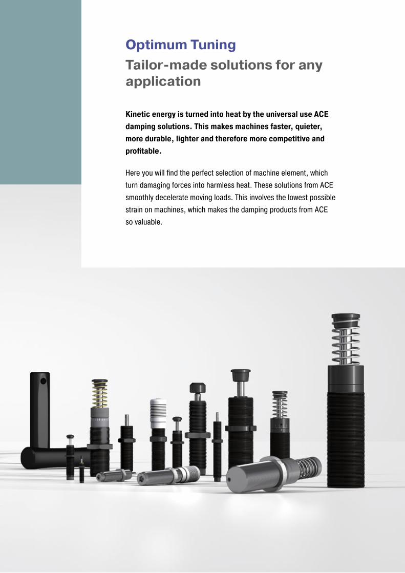
Optimum Tuning Tailor-made solutions for any application
Kinetic energy is turned into heat by the universal use ACE damping solutions. This makes machines faster, quieter, more durable, lighter and therefore more competitive and profitable.
Here you will find the perfect selection of machine element, which turn damaging forces into harmless heat. These solutions from ACE smoothly decelerate moving loads. This involves the lowest possible strain on machines, which makes the damping products from ACE so valuable.
88
ACE Stoßdämpfer GmbH . PO Box 1510 . D-40740 Langenfeld . T +49 (0)2173 - 9226-4100 . [email protected] . www.ace-ace.com
Shock Absorber
Shock Absorber
Raw Material
Finished Product
Production
Rubber Buffer
Raw Material
Finished ProductScrap
Production
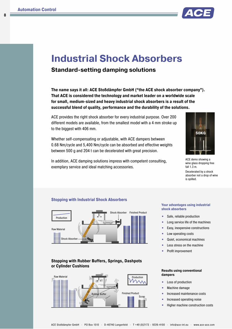
Industrial Shock AbsorbersStandard-setting damping solutions
The name says it all: ACE Stoßdämpfer GmbH (“the ACE shock absorber company”). That ACE is considered the technology and market leader on a worldwide scale for small, medium-sized and heavy industrial shock absorbers is a result of the successful blend of quality, performance and the durability of the solutions.
ACE demo showing a wine glass dropping free fall 1.3 m.
Decelerated by a shock absorber not a drop of wine is spilled.
Stopping with Rubber Buffers, Springs, Dashpots or Cylinder Cushions
Stopping with Industrial Shock Absorbers
Results using conventional dampers
• Loss of production
• Machine damage
• Increased maintenance costs
• Increased operating noise
• Higher machine construction costs
Your advantages using industrial shock absorbers
• Safe, reliable production
• Long service life of the machines
• Easy, inexpensive constructions
• Low operating costs
• Quiet, economical machines
• Less stress on the machine
• Profi t improvement
Automation Control
ACE provides the right shock absorber for every industrial purpose. Over 200 different models are available, from the smallest model with a 4 mm stroke up to the biggest with 406 mm.
Whether self-compensating or adjustable, with ACE dampers between 0.68 Nm/cycle and 5,400 Nm/cycle can be absorbed and effective weights between 500 g and 204 t can be decelerated with great precision.
In addition, ACE damping solutions impress with competent consulting, exemplary service and ideal matching accessories.

9Is
sue
08.2
016
– Sp
ecifi
catio
ns s
ubje
ct to
cha
nge
ACE Stoßdämpfer GmbH . PO Box 1510 . D-40740 Langenfeld . T +49 (0)2173 - 9226-4100 . F +49 (0)2173 - 9226-89 . [email protected] . www.ace-ace.com
*4 *3
p = 400 bar
v = 2 m/s
*2 *1 *0
p = 400 bar
v = 1.5 m/s
p = 400 bar
v = 1 m/s
p = 400 bar
v = 0.5 m/s
p = 0 bar
v = 0 m/s
v
t
F/p
s/t
Stopping Stroke
Stop
ping
For
ce (N
) Hydraulic Dashpot
Springs or Rubber Buffers
Pneumatic Cylinder Cushions
Industrial Shock Absorbers
Comparison of Different Damping Elements
When it comes to slowing down moving masses with constant damping force through the stroke, the industrial shock absorber is the right choice. A comparison demonstrates the differences of the damping elements.
ACE Industrial Shock Absorbers (Uniform stopping force through the entire stroke) The moving load is smoothly and gently brought to rest by a constant resisting force throughout the entire shock absorber stroke. The load is decelerated with the lowest possible force in the shortest possible time eliminating damaging force peaks and shock damage to machines and equipment. This is a linear deceleration force stroke curve and is the curve provided by ACE industrial shock absorbers. In addition they considerably reduce noise pollution.
Hydraulic Dashpot (High stopping force at start of the stroke) With only one metering orifice the moving load is abruptly slowed down at the start of the stroke. The braking force rises to a very high peak at the start of the stroke (giving high shock loads) and then falls away rapidly.
Springs and Rubber Buffers (High stopping forces at end of stroke) At full compression. Also they store energy rather than dissipating it, causing the load to rebound back again.
Air Buffers, Pneumatic Cylinder Cushions (High stopping force at end of stroke) Due to the compressibility of air these have a sharply rising force characteristic towards the end of the stroke. The majority of the energy is absorbed near the end of the stroke.
General Function of the Pressure Chamber
If a moving mass hits the industrial shock absorber, the piston puts the oil in the pressure chamber into motion. The oil is pressed through the metering orifices, which converts the discharged energy into heat. The metering orifices are arranged on the stroke so that the mass is retarded with a constant damping force. The hydraulic pressure is maintained throughout the entire braking process nearly constant.
* The load velocity reduces continously as you travel through the stroke due to the reduction in the number of metering orifices (*) in action. The internal pressure remains essentially constant and thus the force vs. stroke curve remains linear.
ComparisonThe comparison shows the differences of the damping in a direct comparison of stopping force to stopping stroke.
F = force (N), p = internal pressure (bar) s = stroke (m), t = deceleration time (s), v = velocity (m/s)
Technical Information
Industrial Shock Absorbers
10
Issu
e 08
.201
6 –
Spec
ifica
tions
sub
ject
to c
hang
e
ACE Stoßdämpfer GmbH . PO Box 1510 . D-40740 Langenfeld . T +49 (0)2173 - 9226-4100 . F +49 (0)2173 - 9226-89 . [email protected] . www.ace-ace.com
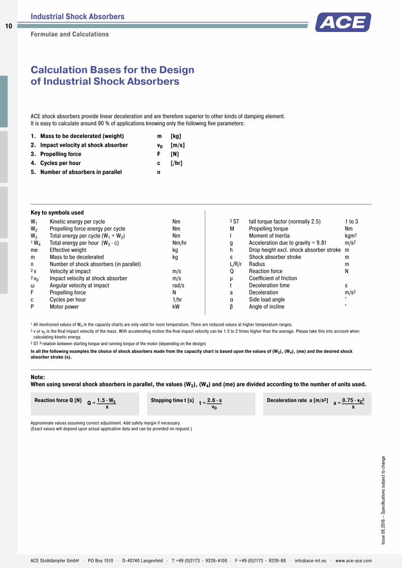
Calculation Bases for the Design of Industrial Shock Absorbers
ACE shock absorbers provide linear deceleration and are therefore superior to other kinds of damping element. It is easy to calculate around 90 % of applications knowing only the following five parameters:
1. Mass to be decelerated (weight) m [kg]2. Impact velocity at shock absorber vD [m/s]3. Propelling force F [N]4. Cycles per hour c [/hr]5. Number of absorbers in parallel n
Key to symbols usedW1 Kinetic energy per cycle NmW2 Propelling force energy per cycle NmW3 Total energy per cycle (W1 + W2) Nm1 W4 Total energy per hour (W3 · c) Nm/hrme Effective weight kgm Mass to be decelerated kgn Number of shock absorbers (in parallel)2 v Velocity at impact m/s2 vD Impact velocity at shock absorber m/sω Angular velocity at impact rad/sF Propelling force Nc Cycles per hour 1/hrP Motor power kW
1 All mentioned values of W4 in the capacity charts are only valid for room temperature. There are reduced values at higher temperature ranges.2 v or vD is the final impact velocity of the mass. With accelerating motion the final impact velocity can be 1.5 to 2 times higher than the average. Please take this into account when
calculating kinetic energy.3 ST =̂ relation between starting torque and running torque of the motor (depending on the design)
In all the following examples the choice of shock absorbers made from the capacity chart is based upon the values of (W3), (W4), (me) and the desired shock absorber stroke (s).
3 ST tall torque factor (normally 2.5) 1 to 3M Propelling torque NmI Moment of Inertia kgm2
g Acceleration due to gravity = 9.81 m/s2
h Drop height excl. shock absorber stroke ms Shock absorber stroke mL/R/r Radius mQ Reaction force N� Coefficient of friction t Deceleration time sa Deceleration m/s2
α Side load angle °β Angle of incline °
Formulae and Calculations
Industrial Shock Absorbers
Reaction force Q [N] Q = 1.5 · W3 s
Stopping time t [s] t = 2.6 · s vD
Deceleration rate a [m/s2] a = 0.75 · vD2
s
Approximate values assuming correct adjustment. Add safety margin if necessary. (Exact values will depend upon actual application data and can be provided on request.)
Note: When using several shock absorbers in parallel, the values (W3), (W4) and (me) are divided according to the number of units used.

11Is
sue
08.2
016
– Sp
ecifi
catio
ns s
ubje
ct to
cha
nge
ACE Stoßdämpfer GmbH . PO Box 1510 . D-40740 Langenfeld . T +49 (0)2173 - 9226-4100 . F +49 (0)2173 - 9226-89 . [email protected] . www.ace-ace.com
Application Formulae Example
1 Mass without propelling force W1 = m · v2 · 0.5W2 = 0W3 = W1 + W2W4 = W3 · cvD = vme = m
m = 100 kgv = 1.5 m/sc = 500 /hr s = 0.050 m (chosen)
W1 = 100 · 1.52 · 0.5 = 113 NmW2 = 0W3 = 113 + 0 = 113 NmW4 = 113 · 500 = 56500 Nm/hrme = m = 100 kg
Chosen from capacity chart:Model MC3350EUM-2 self-compensating
s
m
2 Mass with propelling force W1 = m · v2 · 0.5W2 = F · sW3 = W1 + W2W4 = W3 · cvD = v
me = 2 · W3 vD2
W2 = (F – m · g) · sW2 = (F + m · g) · s
m = 36 kg1 v = 1.5 m/sF = 400 N c = 1000 /hrs = 0.025 m (chosen)
W1 = 36 · 1.52 · 0.5 = 41 NmW2 = 400 · 0.025 = 10 NmW3 = 41 + 10 = 51 NmW4 = 51 · 1000 = 51000 Nm/hrme = 2 · 51 : 1.52 = 45 kg
Chosen from capacity chart:Model MC600EUM self-compensating1 v is the fi nal impact velocity of the mass: With pneumatically propelled systems this can be 1.5 to 2 times the average velocity. Please take this into account when calculating energy.
s
mF
2.1 for vertical motion upwards2.2 for vertical motion downwards
3 Mass with motor drive W1 = m · v2 · 0.5
W2 = 1000 · P · ST · s vW3 = W1 + W2W4 = W3 · cvD = v
me = 2 · W3 vD2
m = 800 kgv = 1.2 m/sST = 2.5P = 4 kW c = 100 /hrs = 0.100 m (chosen)
W1 = 800 · 1.22 · 0.5 = 576 NmW2 = 1000 · 4 · 2.5 · 0.1 : 1.2 = 834 NmW3 = 576 + 834 = 1410 NmW4 = 1410 · 100 = 141000 Nm/hrme = 2 · 1410 : 1.22 = 1958 kg
Chosen from capacity chart:Model MC64100EUM-2 self-compensating
Note: Do not forget to include the rotational energy of motor, coupling and gearbox into calculation for W1.
s
m
P
4 Mass on driven rollers W1 = m · v2 · 0.5W2 = m · � · g · sW3 = W1 + W2W4 = W3 · cvD = v
me = 2 · W3 vD2
m = 250 kgv = 1.5 m/sc = 180 /hr(Steel/Steel) � = 0.2s = 0.050 m (chosen)
W1 = 250 · 1.52 · 0.5 = 281 NmW2 = 250 · 0.2 · 9.81 · 0.05 = 25 NmW3 = 281 + 25 = 306 NmW4 = 306 · 180 = 55080 Nm/hrme = 2 · 306 : 1.52 = 272 kg
Chosen from capacity chart:Model MC4550EUM-2 self-compensating
s
m
5 Swinging mass with propelling force
W1 = m · v2 · 0.5 = 0.5 · I · ω2
W2 = M · s RW3 = W1 + W2W4 = W3 · c
vD = v · R = ω · R L
me = 2 · W3 vD2
m = 20 kgv = 1 m/sM = 50 NmR = 0.5 mL = 0.8 mc = 1500 /hrs = 0.012 m (chosen)
W1 = 20 · 12 · 0,5 = 10 NmW2 = 50 · 0.012 : 0.5 = 1.2 NmW3 = 10 + 1.2 = 11.2 NmW4 = 306 · 180 = 16800 Nm/hrvD = 1 · 0.5 : 0.8 = 0.63 m/sme = 2 · 11.2 : 0.632 = 56 kg
Chosen from capacity chart:Model MC150EUMH self-compensatingCheck the side load angle, tan α = s/R, with regard to “Max.Side Load Angle” in the capacity chart (see example 6.2)
s
m
L R
v(ω)vD
M
6 Free falling mass W1 = m · g · hW2 = m · g · sW3 = W1 + W2W4 = W3 · cvD = √2 · g · h
me = 2 · W3 vD2
m = 30 kgh = 0.5 mc = 400 /hrs = 0.050 m (chosen)
W1 = 30 · 0.5 · 9.81 = 147 NmW2 = 30 · 9.81 · 0.05 = 15 NmW3 = 147 + 15 = 162 NmW4 = 162 · 400 = 64800 Nm/hrvD = √2 · 9.81 · 0.5 = 3.13 m/sme = 2 · 162 : 3.132 = 33 kg
Chosen from capacity chart:Model MC3350EUM-1 self-compensating
m
h
s
Formulae and Calculations
Industrial Shock Absorbers
12
Issu
e 08
.201
6 –
Spec
ifi ca
tions
sub
ject
to c
hang
e
ACE Stoßdämpfer GmbH . PO Box 1510 . D-40740 Langenfeld . T +49 (0)2173 - 9226-4100 . F +49 (0)2173 - 9226-89 . [email protected] . www.ace-ace.com
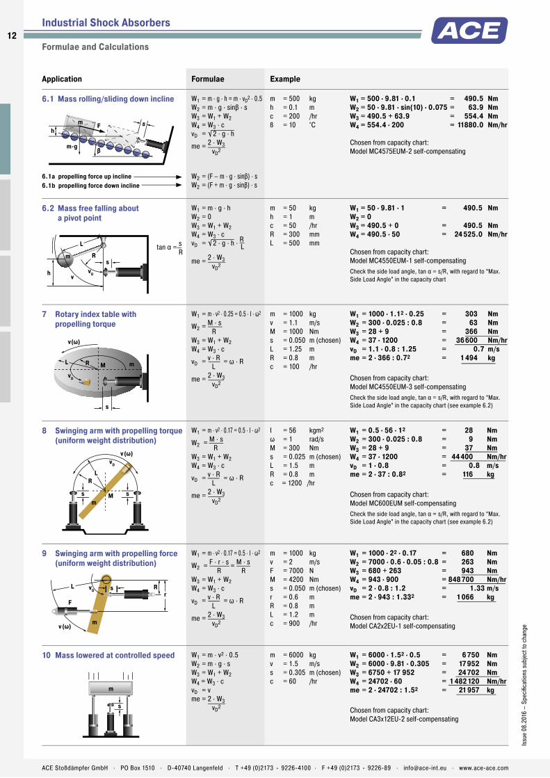
Formulae and Calculations
Industrial Shock Absorbers
Application Formulae Example
6.1 Mass rolling/sliding down incline W1 = m · g · h = m · vD2 · 0.5W2 = m · g · sinβ · sW3 = W1 + W2W4 = W3 · cvD = √2 · g · h
me = 2 · W3 vD2
W2 = (F – m · g · sinβ) · sW2 = (F + m · g · sinβ) · s
m = 500 kgh = 0.1 mc = 200 /hrß = 10 °C
W1 = 500 · 9.81 · 0.1 = 490.5 NmW2 = 50 · 9.81 · sin(10) · 0.075 = 63.9 NmW3 = 490.5 + 63.9 = 554.4 NmW4 = 554.4 · 200 = 11880.0 Nm/hr
Chosen from capacity chart:Model MC4575EUM-2 self-compensating
smh
βm·g
F
6.1a propelling force up incline 6.1b propelling force down incline
6.2 Mass free falling about a pivot point
W1 = m · g · hW2 = 0W3 = W1 + W2W4 = W3 · cvD = √2 · g · h · R
L
me = 2 · W3 vD2
m = 50 kgh = 1 mc = 50 /hrR = 300 mmL = 500 mm
W1 = 50 · 9.81 · 1 = 490.5 NmW2 = 0W3 = 490.5 + 0 = 490.5 NmW4 = 490.5 · 50 = 24 525.0 Nm/hr
Chosen from capacity chart:Model MC4550EUM-1 self-compensatingCheck the side load angle, tan α = s/R, with regard to “Max. Side Load Angle” in the capacity chart
sVm
h vvD
L
Rtan α = s R
7 Rotary index table with propelling torque
W1 = m · v2 · 0.25 = 0.5 · I · ω2
W2 = M · s RW3 = W1 + W2W4 = W3 · c
vD = v · R = ω · R L
me = 2 · W3 vD2
m = 1000 kgv = 1.1 m/sM = 1000 Nms = 0.050 m (chosen)L = 1.25 mR = 0.8 mc = 100 /hr
W1 = 1000 · 1.12 · 0.25 = 303 NmW2 = 300 · 0.025 : 0.8 = 63 NmW3 = 28 + 9 = 366 NmW4 = 37 · 1200 = 36600 Nm/hrvD = 1.1 · 0.8 : 1.25 = 0.7 m/sme = 2 · 366 : 0.72 = 1494 kg
Chosen from capacity chart:Model MC4550EUM-3 self-compensatingCheck the side load angle, tan α = s/R, with regard to “Max.Side Load Angle” in the capacity chart (see example 6.2)s
mMRL
vD
v(ω)
8 Swinging arm with propelling torque (uniform weight distribution)
W1 = m · v2 · 0.17 = 0.5 · I · ω2
W2 = M · s RW3 = W1 + W2W4 = W3 · c
vD = v · R = ω · R L
me = 2 · W3 vD2
I = 56 kgm2
ω = 1 rad/sM = 300 Nms = 0.025 m (chosen)L = 1.5 mR = 0.8 mc = 1200 /hr
W1 = 0.5 · 56 · 12 = 28 NmW2 = 300 · 0.025 : 0.8 = 9 NmW3 = 28 + 9 = 37 NmW4 = 37 · 1200 = 44400 Nm/hrvD = 1 · 0.8 = 0.8 m/sme = 2 · 37 : 0.82 = 116 kg
Chosen from capacity chart:Model MC600EUM self-compensatingCheck the side load angle, tan α = s/R, with regard to “Max.Side Load Angle” in the capacity chart (see example 6.2)
ss
vD
M
LR
v(ω)
m
9 Swinging arm with propelling force (uniform weight distribution)
W1 = m · v2 · 0.17 = 0.5 · I · ω2
W2 = F · r · s = M · s R RW3 = W1 + W2W4 = W3 · c
vD = v · R = ω · R L
me = 2 · W3 vD2
m = 1000 kgv = 2 m/sF = 7000 NM = 4200 Nms = 0.050 m (chosen)r = 0.6 mR = 0.8 mL = 1.2 mc = 900 /hr
W1 = 1000 · 22 · 0.17 = 680 NmW2 = 7000 · 0.6 · 0.05 : 0.8 = 263 NmW3 = 680 + 263 = 943 NmW4 = 943 · 900 = 848700 Nm/hrvD = 2 · 0.8 : 1.2 = 1.33 m/sme = 2 · 943 : 1.332 = 1066 kg
Chosen from capacity chart:Model CA2x2EU-1 self-compensating
svDL R
v(ω) m
Fr
10 Mass lowered at controlled speed W1 = m · v2 · 0.5W2 = m · g · sW3 = W1 + W2W4 = W3 · cvD = vme = 2 · W3 vD2
m = 6000 kgv = 1.5 m/ss = 0.305 m (chosen)c = 60 /hr
W1 = 6000 · 1.52 · 0.5 = 6750 NmW2 = 6000 · 9.81 · 0.305 = 17952 NmW3 = 6750 + 17 952 = 24702 NmW4 = 24702 · 60 = 1482120 Nm/hrme = 2 · 24702 : 1.52 = 21957 kg
Chosen from capacity chart:Model CA3x12EU-2 self-compensating
s
m
13Is
sue
08.2
016
– Sp
ecifi
catio
ns s
ubje
ct to
cha
nge
ACE Stoßdämpfer GmbH . PO Box 1510 . D-40740 Langenfeld . T +49 (0)2173 - 9226-4100 . F +49 (0)2173 - 9226-89 . [email protected] . www.ace-ace.com
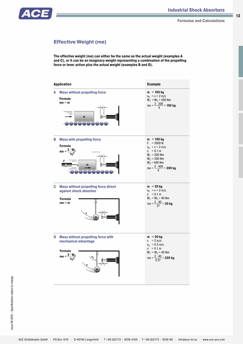
The effective weight (me) can either be the same as the actual weight (examples A and C), or it can be an imaginary weight representing a combination of the propelling force or lever action plus the actual weight (examples B and D).
Effective Weight (me)
Application Example
A Mass without propelling force m = 100 kgvD = v = 2 m/sW1 = W3 = 200 Nm
me = 2 · 200 = 100 kg 4s
m
Formula me = m
B Mass with propelling force m = 100 kgF = 2000 NvD = v = 2 m/ss = 0.1 mW1 = 200 NmW2 = 200 NmW3 = 400 Nm
me = 2 · 400 = 200 kg 4
s
mF
Formula me = 2 · W3 vD2
C Mass without propelling force direct against shock absorber
m = 20 kgvD = v = 2 m/ss = 0.1 mW1 = W3 = 40 Nm
me = 2 · 40 = 20 kg 22
svm
Formula me = m
D Mass without propelling force with mechanical advantage
m = 20 kgv = 2 m/svD = 0.5 m/ss = 0.1 mW1 = W3 = 40 Nm
me = 2 · 40 = 320 kg 0.52
sv
vD
m
Formula me = 2 · W3 vD2
Formulae and Calculations
Industrial Shock Absorbers
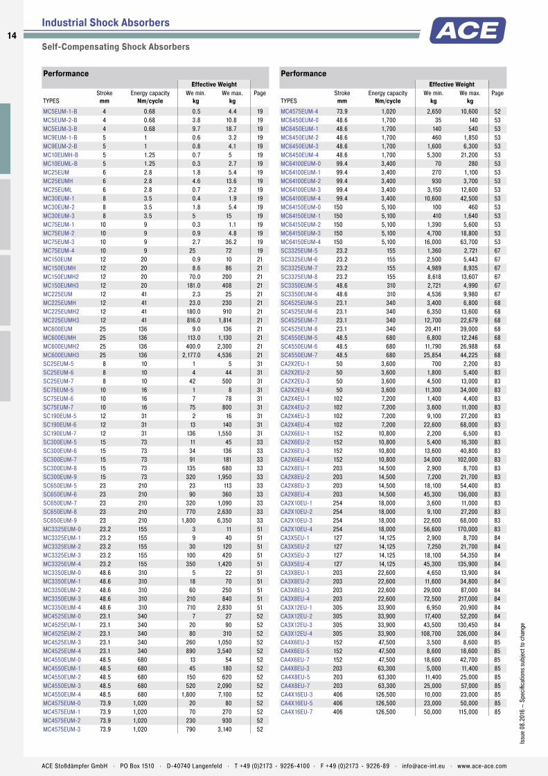
Industrial Shock Absorbers
Self-Compensating Shock Absorbers
PerformanceEffective Weight
TYPESStroke
mmEnergy capacity
Nm/cycleWe min.
kgWe max.
kgPage
MC5EUM-1-B 4 0.68 0.5 4.4 19MC5EUM-2-B 4 0.68 3.8 10.8 19MC5EUM-3-B 4 0.68 9.7 18.7 19MC9EUM-1-B 5 1 0.6 3.2 19MC9EUM-2-B 5 1 0.8 4.1 19MC10EUMH-B 5 1.25 0.7 5 19MC10EUML-B 5 1.25 0.3 2.7 19MC25EUM 6 2.8 1.8 5.4 19MC25EUMH 6 2.8 4.6 13.6 19MC25EUML 6 2.8 0.7 2.2 19MC30EUM-1 8 3.5 0.4 1.9 19MC30EUM-2 8 3.5 1.8 5.4 19MC30EUM-3 8 3.5 5 15 19MC75EUM-1 10 9 0.3 1.1 19MC75EUM-2 10 9 0.9 4.8 19MC75EUM-3 10 9 2.7 36.2 19MC75EUM-4 10 9 25 72 19MC150EUM 12 20 0.9 10 21MC150EUMH 12 20 8.6 86 21MC150EUMH2 12 20 70.0 200 21MC150EUMH3 12 20 181.0 408 21MC225EUM 12 41 2.3 25 21MC225EUMH 12 41 23.0 230 21MC225EUMH2 12 41 180.0 910 21MC225EUMH3 12 41 816.0 1,814 21MC600EUM 25 136 9.0 136 21MC600EUMH 25 136 113.0 1,130 21MC600EUMH2 25 136 400.0 2,300 21MC600EUMH3 25 136 2,177.0 4,536 21SC25EUM-5 8 10 1 5 31SC25EUM-6 8 10 4 44 31SC25EUM-7 8 10 42 500 31SC75EUM-5 10 16 1 8 31SC75EUM-6 10 16 7 78 31SC75EUM-7 10 16 75 800 31SC190EUM-5 12 31 2 16 31SC190EUM-6 12 31 13 140 31SC190EUM-7 12 31 136 1,550 31SC300EUM-5 15 73 11 45 33SC300EUM-6 15 73 34 136 33SC300EUM-7 15 73 91 181 33SC300EUM-8 15 73 135 680 33SC300EUM-9 15 73 320 1,950 33SC650EUM-5 23 210 23 113 33SC650EUM-6 23 210 90 360 33SC650EUM-7 23 210 320 1,090 33SC650EUM-8 23 210 770 2,630 33SC650EUM-9 23 210 1,800 6,350 33MC3325EUM-0 23.2 155 3 11 51MC3325EUM-1 23.2 155 9 40 51MC3325EUM-2 23.2 155 30 120 51MC3325EUM-3 23.2 155 100 420 51MC3325EUM-4 23.2 155 350 1,420 51MC3350EUM-0 48.6 310 5 22 51MC3350EUM-1 48.6 310 18 70 51MC3350EUM-2 48.6 310 60 250 51MC3350EUM-3 48.6 310 210 840 51MC3350EUM-4 48.6 310 710 2,830 51MC4525EUM-0 23.1 340 7 27 52MC4525EUM-1 23.1 340 20 90 52MC4525EUM-2 23.1 340 80 310 52MC4525EUM-3 23.1 340 260 1,050 52MC4525EUM-4 23.1 340 890 3,540 52MC4550EUM-0 48.5 680 13 54 52MC4550EUM-1 48.5 680 45 180 52MC4550EUM-2 48.5 680 150 620 52MC4550EUM-3 48.5 680 520 2,090 52MC4550EUM-4 48.5 680 1,800 7,100 52MC4575EUM-0 73.9 1,020 20 80 52MC4575EUM-1 73.9 1,020 70 270 52MC4575EUM-2 73.9 1,020 230 930 52MC4575EUM-3 73.9 1,020 790 3,140 52
PerformanceEffective Weight
TYPESStroke
mmEnergy capacity
Nm/cycleWe min.
kgWe max.
kgPage
MC4575EUM-4 73.9 1,020 2,650 10,600 52MC6450EUM-0 48.6 1,700 35 140 53MC6450EUM-1 48.6 1,700 140 540 53MC6450EUM-2 48.6 1,700 460 1,850 53MC6450EUM-3 48.6 1,700 1,600 6,300 53MC6450EUM-4 48.6 1,700 5,300 21,200 53MC64100EUM-0 99.4 3,400 70 280 53MC64100EUM-1 99.4 3,400 270 1,100 53MC64100EUM-2 99.4 3,400 930 3,700 53MC64100EUM-3 99.4 3,400 3,150 12,600 53MC64100EUM-4 99.4 3,400 10,600 42,500 53MC64150EUM-0 150 5,100 100 460 53MC64150EUM-1 150 5,100 410 1,640 53MC64150EUM-2 150 5,100 1,390 5,600 53MC64150EUM-3 150 5,100 4,700 18,800 53MC64150EUM-4 150 5,100 16,000 63,700 53SC3325EUM-5 23.2 155 1,360 2,721 67SC3325EUM-6 23.2 155 2,500 5,443 67SC3325EUM-7 23.2 155 4,989 8,935 67SC3325EUM-8 23.2 155 8,618 13,607 67SC3350EUM-5 48.6 310 2,721 4,990 67SC3350EUM-6 48.6 310 4,536 9,980 67SC4525EUM-5 23.1 340 3,400 6,800 68SC4525EUM-6 23.1 340 6,350 13,600 68SC4525EUM-7 23.1 340 12,700 22,679 68SC4525EUM-8 23.1 340 20,411 39,000 68SC4550EUM-5 48.5 680 6,800 12,246 68SC4550EUM-6 48.5 680 11,790 26,988 68SC4550EUM-7 48.5 680 25,854 44,225 68CA2X2EU-1 50 3,600 700 2,200 83CA2X2EU-2 50 3,600 1,800 5,400 83CA2X2EU-3 50 3,600 4,500 13,000 83CA2X2EU-4 50 3,600 11,300 34,000 83CA2X4EU-1 102 7,200 1,400 4,400 83CA2X4EU-2 102 7,200 3,600 11,000 83CA2X4EU-3 102 7,200 9,100 27,200 83CA2X4EU-4 102 7,200 22,600 68,000 83CA2X6EU-1 152 10,800 2,200 6,500 83CA2X6EU-2 152 10,800 5,400 16,300 83CA2X6EU-3 152 10,800 13,600 40,800 83CA2X6EU-4 152 10,800 34,000 102,000 83CA2X8EU-1 203 14,500 2,900 8,700 83CA2X8EU-2 203 14,500 7,200 21,700 83CA2X8EU-3 203 14,500 18,100 54,400 83CA2X8EU-4 203 14,500 45,300 136,000 83CA2X10EU-1 254 18,000 3,600 11,000 83CA2X10EU-2 254 18,000 9,100 27,200 83CA2X10EU-3 254 18,000 22,600 68,000 83CA2X10EU-4 254 18,000 56,600 170,000 83CA3X5EU-1 127 14,125 2,900 8,700 84CA3X5EU-2 127 14,125 7,250 21,700 84CA3X5EU-3 127 14,125 18,100 54,350 84CA3X5EU-4 127 14,125 45,300 135,900 84CA3X8EU-1 203 22,600 4,650 13,900 84CA3X8EU-2 203 22,600 11,600 34,800 84CA3X8EU-3 203 22,600 29,000 87,000 84CA3X8EU-4 203 22,600 72,500 217,000 84CA3X12EU-1 305 33,900 6,950 20,900 84CA3X12EU-2 305 33,900 17,400 52,200 84CA3X12EU-3 305 33,900 43,500 130,450 84CA3X12EU-4 305 33,900 108,700 326,000 84CA4X6EU-3 152 47,500 3,500 8,600 85CA4X6EU-5 152 47,500 8,600 18,600 85CA4X6EU-7 152 47,500 18,600 42,700 85CA4X8EU-3 203 63,300 5,000 11,400 85CA4X8EU-5 203 63,300 11,400 25,000 85CA4X8EU-7 203 63,300 25,000 57,000 85CA4X16EU-3 406 126,500 10,000 23,000 85CA4X16EU-5 406 126,500 23,000 50,000 85CA4X16EU-7 406 126,500 50,000 115,000 85
14
Issu
e 08
.201
6 –
Spec
ifica
tions
sub
ject
to c
hang
e
ACE Stoßdämpfer GmbH . PO Box 1510 . D-40740 Langenfeld . T +49 (0)2173 - 9226-4100 . F +49 (0)2173 - 9226-89 . [email protected] . www.ace-ace.com
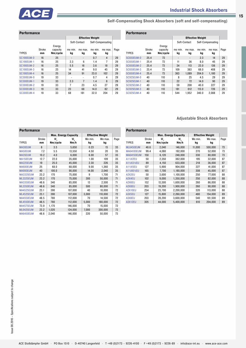
Industrial Shock Absorbers
Self-Compensating Shock Absorbers (soft and self-compensating)
PerformanceEffective Weight
Soft-Contact Self-Compensating
TYPESStroke
mm
Energy capacity
Nm/cycleme min.
kgme max.
kgme min.
kgme max.
kgPage
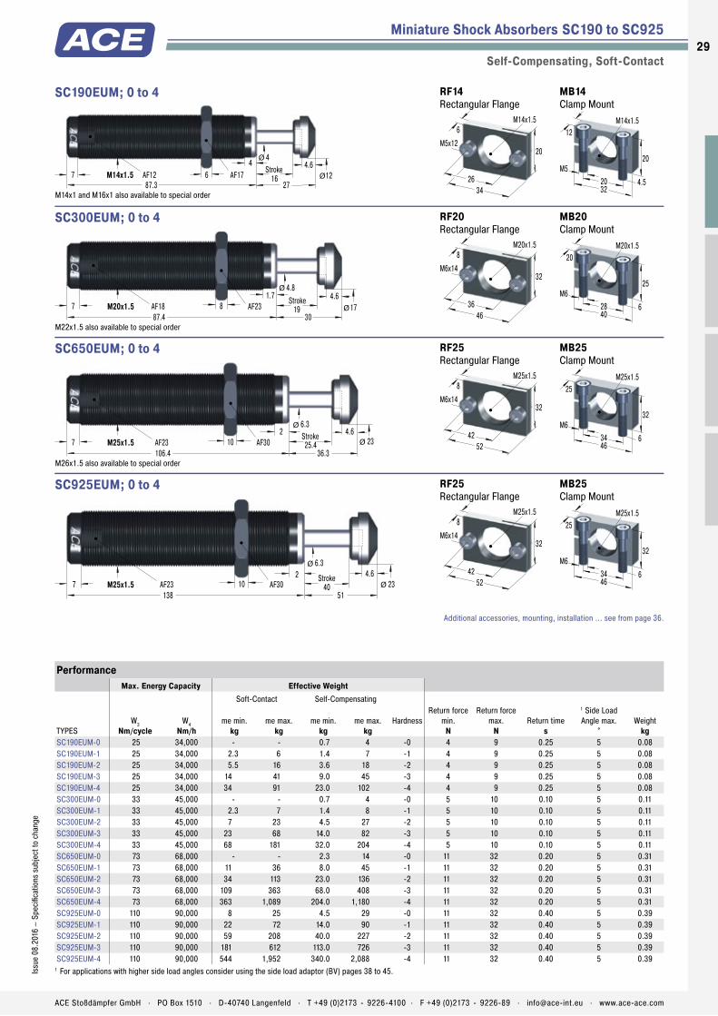
SC190EUM-0 16 25 - - 0.7 4 29SC190EUM-1 16 25 2.3 6 1.4 7 29SC190EUM-2 16 25 5.5 16 3.6 18 29SC190EUM-3 16 25 14 41 9.0 45 29SC190EUM-4 16 25 34 91 23.0 102 29SC300EUM-0 19 33 - - 0.7 4 29SC300EUM-1 19 33 2.3 7 1.4 8 29SC300EUM-2 19 33 7 23 4.5 27 29SC300EUM-3 19 33 23 68 14.0 82 29SC300EUM-4 19 33 68 181 32.0 204 29
PerformanceEffective Weight
Soft-Contact Self-Compensating
TYPESStroke
mm
Energy capacity
Nm/cycleme min.
kgme max.
kgme min.
kgme max.
kgPage
SC650EUM-0 25.4 73 - - 2.3 14 29SC650EUM-1 25.4 73 11 36 8.0 45 29SC650EUM-2 25.4 73 34 113 23.0 136 29SC650EUM-3 25.4 73 109 363 68.0 408 29SC650EUM-4 25.4 73 363 1,089 204.0 1,180 29SC925EUM-0 40 110 8 25 4.5 29 29SC925EUM-1 40 110 22 72 14.0 90 29SC925EUM-2 40 110 59 208 40.0 227 29SC925EUM-3 40 110 181 612 113.0 726 29SC925EUM-4 40 110 544 1,952 340.0 2,088 29
PerformanceMax. Energy Capacity Effective Weight
TYPESStroke
mmW3
Nm/cycleW4
Nm/hWe min.
kgWe max.
kgPage
MA30EUM 8 3.5 5,650 0.23 15 35MA50EUM 7.2 5.5 13,550 4.50 20 35MA35EUM 10.2 4.0 6,000 6.00 57 35MA150EUM 12.7 22.0 35,000 1.00 109 35MA225EUM 19 25.0 45,000 2.30 226 35MA600EUM 25 68.0 68,000 9.00 1,360 35MA900EUM 40 100.0 90,000 14.00 2,040 35MA3325EUM 23.2 170 75,000 9 1,700 71ML3325EUM 23.2 170 75,000 300 50,000 71MA3350EUM 48.6 340 85,000 13 2,500 71ML3350EUM 48.6 340 85,000 500 80,000 71MA4525EUM 23.1 390 107,000 40 10,000 72ML4525EUM 23.1 390 107,000 3,000 110,000 72MA4550EUM 48.5 780 112,000 70 14,500 72ML4550EUM 48.5 780 112,000 5,000 180,000 72MA4575EUM 73.9 1,170 146,000 70 15,000 72ML6425EUM 23.2 1,020 124,000 7,000 300,000 73MA6450EUM 48.6 2,040 146,000 220 50,000 73
PerformanceMax. Energy Capacity Effective Weight
TYPESStroke
mmW3
Nm/cycleW4
Nm/hWe min.
kgWe max.
kgPage
ML6450EUM 48.6 2,040 146,000 11,000 500,000 73MA64100EUM 99.4 4,080 192,000 270 52,000 73MA64150EUM 150 6,120 248,000 330 80,000 73A1½X2EU 50 2,350 362,000 195 32,000 87A1½X3½EU 89 4,150 633,000 218 36,000 87A1½X5EU 127 5,900 904,000 227 41,000 87A1½X6½EU 165 7,700 1,180,000 308 45,000 87A2X2EU 50 3,600 1,100,000 250 77,000 88A2X4EU 102 9,000 1,350,000 250 82,000 88A2X6EU 152 13,500 1,600,000 260 86,000 88A2X8EU 203 19,200 1,900,000 260 90,000 88A2X10EU 254 23,700 2,200,000 320 113,000 88A3X5EU 127 15,800 2,260,000 480 154,000 89A3X8EU 203 28,200 3,600,000 540 181,500 89A3X12EU 305 44,000 5,400,000 610 204,000 89
Adjustable Shock Absorbers
15Is
sue
08.2
016
– Sp
ecifi
catio
ns s
ubje
ct to
cha
nge
ACE Stoßdämpfer GmbH . PO Box 1510 . D-40740 Langenfeld . T +49 (0)2173 - 9226-4100 . F +49 (0)2173 - 9226-89 . [email protected] . www.ace-ace.com

1616
ACE Stoßdämpfer GmbH . PO Box 1510 . D-40740 Langenfeld . T +49 (0)2173 - 9226-4100 . [email protected] . www.ace-ace.com
Automation Control
Miniature shock absorbers from ACE are tried-and-tested quality pro-ducts used in millions of industrial construction designs throughout the world. They optimise machines in an equally reliable and effective way by decelerating loads quickly and without recoil.
The compact, maintenance-free, hydraulic machine elements can be easily and quickly integrated in any construction design and certain models can be directly integrated in pneumatic cylinders. They reduce the load on handling devices, rotary and pivoting actuators, linear cylinders and many other industrial applica-tions and increase their effi ciency. Innovative ACE sealing techniques and shock absorber bodies and inner pressure chambers, fully machined from solid high tensile alloy, tube-shaped steel, ensure a long service life.
Miniature Shock AbsorbersTuning for almost any design
Easy, inexpensive constructions
Large variety of models for every purpose
Less stress on the machine
Reduced operating costs
Maintenance-free
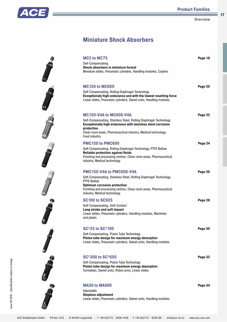
Product Families
Overview
Miniature Shock Absorbers
MC5 to MC75 Self-Compensating Shock absorbers in miniature formatMiniature slides, Pneumatic cylinders, Handling modules, Copiers
Page 18
MC150 to MC600 Self-Compensating, Rolling Diaphragm Technology Exceptionaly high endurance and with the lowest resetting forceLinear slides, Pneumatic cylinders, Swivel units, Handling modules
Page 20
MC150-V4A to MC600-V4A Self-Compensating, Stainless Steel, Rolling Diaphragm Technology Exceptionally high endurance with stainless steel corrosion protectionClean room areas, Pharmaceutical industry, Medical technology, Food industry
Page 22
PMC150 to PMC600 Self-Compensating, Rolling Diaphragm Technology, PTFE Bellow Reliable protection against fl uidsFinishing and processing centres, Clean room areas, Pharmaceutical industry, Medical technology
Page 24
PMC150-V4A to PMC600-V4A Self-Compensating, Stainless Steel, Rolling Diaphragm Technology, PTFE Bellow Optimum corrosion protectionFinishing and processing centres, Clean room areas, Pharmaceutical industry, Medical technology
Page 26
SC190 to SC925 Self-Compensating, Soft-Contact Long stroke and soft impactLinear slides, Pneumatic cylinders, Handling modules, Machines and plants
Page 28
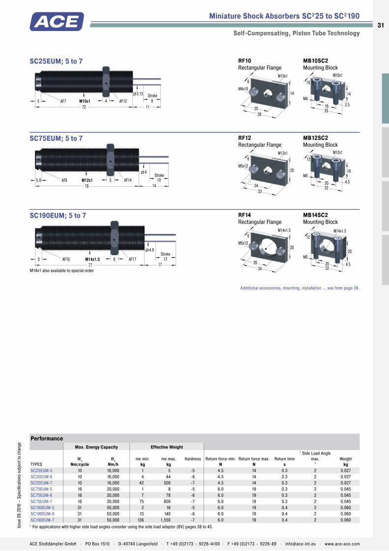
SC²25 to SC²190 Self-Compensating, Piston Tube Technology Piston tube design for maximum energy absorptionLinear slides, Pneumatic cylinders, Swivel units, Handling modules
Page 30
SC²300 to SC²650 Self-Compensating, Piston Tube Technology Piston tube design for maximum energy absorptionTurntables, Swivel units, Robot arms, Linear slides
Page 32
MA30 to MA900 Adjustable Stepless adjustmentLinear slides, Pneumatic cylinders, Swivel units, Handling modules
Page 34
17Is
sue
08.2
016
– Sp
ecifi
catio
ns s
ubje
ct to
cha
nge
ACE Stoßdämpfer GmbH . PO Box 1510 . D-40740 Langenfeld . T +49 (0)2173 - 9226-4100 . F +49 (0)2173 - 9226-89 . [email protected] . www.ace-ace.com
Easy, inexpensive constructions
Large variety of models for every purpose
Reduced operating costs
Maintenance-free

Accumulator
Piston Rod
Rod Button
Locknut
Main Bearing
Seals
Positive Stop
Outer Body
Piston
Return Spring
Pressure Chamber
Slot
Technical Data
Ideal for compact, effi cient designs: The MC5 to 75 series impresses users with their reduced dimensions and their very short overall lengths and low resetting forces after braking.
The outer body of each damper, produced from one solid piece, are fi lled with temperature stable oil, offer a continuous thread incl. a supplied lock nut and also have an integrated positive stop. These hydraulic machine elements from ACE, are ready for immediate installation and are maintenance-free. A comprehensive range of energy absorption with a wide range of effective weight potential are further benefi ts in these minature units.
These miniature shock absorbers are perfectly suited to use in applications such as mechani-cal engineering, medical and electro-technolo-gy and robotics.
MC5 to MC75Miniature Shock Absorbers Shock absorbers in miniature format
Miniature Shock Absorbers
Self-Compensating
Energy capacity: 0.68 Nm/Cycle to 9 Nm/CycleImpact velocity range: 0.15 m/s to 4 m/sOperating temperature range: -10 °C to +66 °CMounting: In any positionPositive stop: IntegratedMaterial: Outer body, Accessories: Steel corrosion-resistant coating; Piston rod: Hardened stainless steel; Rod end button: Steel, MC25 and MC75: Elastomer Insert; Locknut: Steel, MC5 and MC9: AluminiumDamping medium: Oil, temperature stable
Application fi eld: Miniature slides, Pneu-matic cylinders, Handling modules, CopiersNote: If precise end position datum is required consider use of the stop collar type AH.Safety instructions: External materials in the surrounding area can attack the seal compo-nents and lead to a shorter service life. Please contact ACE for appropriate solution sugges-tions. Do not paint the shock absorbers due to heat emission.On request: Increased corrosion protection. Special fi nishes. Models without rod end button also available on request.
18
Issu
e 08
.201
6 –
Spec
ifi ca
tions
sub
ject
to c
hang
e
ACE Stoßdämpfer GmbH . PO Box 1510 . D-40740 Langenfeld . T +49 (0)2173 - 9226-4100 . F +49 (0)2173 - 9226-89 . [email protected] . www.ace-ace.com

Accumulator
Piston Rod
Rod Button
Locknut
Main Bearing
Seals
Positive Stop
Outer Body
Piston
Return Spring
Pressure Chamber
Slot
Miniature Shock Absorbers MC5 to MC75
Self-Compensating
4.6 Stroke1
AF8 4.128
M5x0.58.1
2.4 3.31.5Ø
Ø4
MC5EUM
MB5SC2 Mounting Block
20
10
3
M5x0.5
M3
12
8
2.5 2.5Stroke
2AF8
526
M6x0.510
2.7 4.8
2Ø
Ø
MC9EUM
MB6SC2 Mounting Block
20
10
3
M6x0.5
M3
12
8
RF6 Rectangular Flange
20
10
5M6x0.5
14
M3x8
5 4 Stroke2 2
AF105
28.54.8M8x1
102
Ø
Ø
MC10EUM still available in future
M8x0.75 also available to order
5Stroke
3.2 3
AF126.6
43
7.6M10x1
14.64 5AF5
Ø
Ø
MC25EUM
MB10SC2 Mounting Block
25
14
3.5
M10x1
M4
16
10
RF10 Rectangular Flange
28
14
6M10x1
20
M4x10
4.1 3 Stroke2.5 2
AF108
40.9
6.4M8x113.1
2.5Ø
Ø
MC30EUM for use on new installations
5Stroke
3.2 3
AF14 1052
7.6M12x1
18
5 3
Ø
Ø
MC75EUM
MB12 Clamp Mount
32
16
4.5
M12x1
M5
20
12
RF12 Rectangular Flange
32
20
6M12x1
24
M5x12
Additional accessories, mounting, installation ... see from page 36.
PerformanceMax. Energy Capacity Effective Weight
TYPESW3
Nm/cycleW4
Nm/hme min.
kgme max.
kgReturn force min.
NReturn force max.
NReturn time
s
1 Side Load Angle max.
°Weight
kgMC5EUM-1-B 0.68 2,040 0.5 4.4 1 5 0.2 2 0.003MC5EUM-2-B 0.68 2,040 3.8 10.8 1 5 0.2 2 0.003MC5EUM-3-B 0.68 2,040 9.7 18.7 1 5 0.2 2 0.003MC9EUM-1-B 1 2,000 0.6 3.2 2 4 0.3 2 0.005MC9EUM-2-B 1 2,000 0.8 4.1 2 4 0.3 2 0.005MC10EUML-B 1.25 4,000 0.3 2.7 2 4 0.6 3 0.010MC10EUMH-B 1.25 4,000 0.7 5 2 4 0.6 3 0.010MC25EUML 2.8 22,600 0.7 2.2 3 6 0.3 2 0.020MC25EUM 2.8 22,600 1.8 5.4 3 6 0.3 2 0.020MC25EUMH 2.8 22,600 4.6 13.6 3 6 0.3 2 0.020MC30EUM-1 3.5 5,600 0.4 1.9 2 6 0.3 2 0.010MC30EUM-2 3.5 5,600 1.8 5.4 2 6 0.3 2 0.010MC30EUM-3 3.5 5,600 5 15 2 6 0.3 2 0.010MC75EUM-1 9 28,200 0.3 1.1 4 9 0.3 2 0.030MC75EUM-2 9 28,200 0.9 4.8 4 9 0.3 2 0.030MC75EUM-3 9 28,200 2.7 36.2 4 9 0.3 2 0.030MC75EUM-4 9 28,200 25 72 4 9 0.3 2 0.030
1 For applications with higher side load angles consider using the side load adaptor (BV) pages 38 to 45.
19Is
sue
08.2
016
– Sp
ecifi
catio
ns s
ubje
ct to
cha
nge
ACE Stoßdämpfer GmbH . PO Box 1510 . D-40740 Langenfeld . T +49 (0)2173 - 9226-4100 . F +49 (0)2173 - 9226-89 . [email protected] . www.ace-ace.com

Piston Rod
Rolling Diaphragm Seal
Locknut
Self-Retaining Main Bearing
Outer Body
Diaphragm Locator
O-Ring
Piston with Integral Positive Stop
Pressure Chamber with Metering Orifices
Internal Hex Socket
Technical Data
Tried-and-tested and durable: Due to a hermetically sealed rolling diaphragm in each absorber, the MC150 to MC600 product family is suitable for an exceptional high lifetime of use with up to 25 million cycles. The rolling diaphragm technology perfected by ACE ensures complete separation of the damping fl uid from the surrounding air. This makes direct installation in a pressure chamber e.g. as end stop damping in pneumatic cylinders up to approx. 7 bar possible.
The rolling diaphragm also benefi ts the very low return forces of these maintenance-free, ready-to-install absorbers. Progressive energy capacities, with a wide range of effective weight potential make these miniature shock absorbers, complete with an integrated positive stop a winner. Furthermore, the use of a side load adapter allows impact angles of up to 25°.
Miniature shock absorbers capable of universal mounting even inside a cylinder and also available in stainless steel options. They are often used in mechanical and plant engineer-ing, and a multitude of other applications.
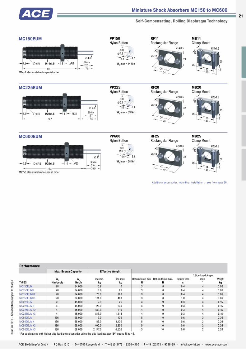
MC150 to MC600Miniature Shock Absorbers Exceptionaly high endurance and with the lowest resetting force
Miniature Shock Absorbers
Self-Compensating, Rolling Diaphragm Technology
Energy capacity: 20 Nm/Cycle to 136 Nm/CycleImpact velocity range: 0.06 m/s to 6 m/s. Other speeds on request.Operating temperature range: 0 °C to 66 °CMounting: In any positionPositive stop: IntegratedMaterial: Outer body, Accessories: Steel corrosion-resistant coating; Main bearing: Plastic; Piston rod: Hardened stainless steel (1.4125, AISI 440C); Rolling diaphragm: EPDMDamping medium: Oil, temperature stable
Application fi eld: Linear slides, Pneumatic cylinders, Swivel units, Handling modulesNote: If precise end position datum is required consider use of the stop collar type AH.Safety instructions: External materials in the surrounding area can attack the rolling seal and lead to a shorter service life. Please contact ACE for appropriate solution sugges-tions. Suitable for use in pressure chambers up to 7 bar.On request: Increased corrosion protection. Special threads or other special options.
20
Issu
e 08
.201
6 –
Spec
ifi ca
tions
sub
ject
to c
hang
e
ACE Stoßdämpfer GmbH . PO Box 1510 . D-40740 Langenfeld . T +49 (0)2173 - 9226-4100 . F +49 (0)2173 - 9226-89 . [email protected] . www.ace-ace.com
Piston Rod
Rolling Diaphragm Seal
Locknut
Self-Retaining Main Bearing
Outer Body
Diaphragm Locator
O-Ring
Piston with Integral Positive Stop
Pressure Chamber with Metering Orifices
Internal Hex Socket
Miniature Shock Absorbers MC150 to MC600
Self-Compensating, Rolling Diaphragm Technology
M14x1.57.2 6 AF17 12.7Stroke
4.8
69.1 17.5
AF6
Ø
MC150EUM
M14x1 also available to special order
MB14 Clamp Mount
32
20
4.5
M14x1.5
M520
12
RF14 Rectangular Flange
34
20
6M14x1.5
26
M5x12
PP150 Nylon Button
12
4.79.4
4.8Ø
Ø
W3 max = 14 Nm
M20x1.57.2 8 AF23 12.7Stroke
6.3
79.2 17.5
AF8
Ø
MC225EUM
MB20 Clamp Mount
40
25
6
M20x1.5
M628
20
RF20 Rectangular Flange
46
32
8M20x1.5
36
M6x14
PP225 Nylon Button
17
3.98.8
6.3Ø
Ø
W3 max = 33 Nm
M25x1.57.3 10 AF30 25.4Stroke
8
110.3 30.9
AF10
Ø
MC600EUM
M27x3 also available to special order
MB25 Clamp Mount
46
32
6
M25x1.5
M634
25
RF25 Rectangular Flange
52
32
8M25x1.5
42
M6x14
PP600 Nylon Button
23
5.410.6
8ØØ
W3 max = 68 Nm
Additional accessories, mounting, installation ... see from page 36.
PerformanceMax. Energy Capacity Effective Weight
TYPESW3
Nm/cycleW4
Nm/hme min.
kgme max.
kgReturn force min.
NReturn force max.
NReturn time
s
1 Side Load Angle max.
°Weight
kgMC150EUM 20 34,000 0.9 10 3 8 0.4 4 0.06MC150EUMH 20 34,000 8.6 86 3 8 0.4 4 0.06MC150EUMH2 20 34,000 70.0 200 3 8 0.4 4 0.06MC150EUMH3 20 34,000 181.0 408 3 8 1.0 4 0.06MC225EUM 41 45,000 2.3 25 4 9 0.3 4 0.15MC225EUMH 41 45,000 23.0 230 4 9 0.3 4 0.15MC225EUMH2 41 45,000 180.0 910 4 9 0.3 4 0.15MC225EUMH3 41 45,000 816.0 1,814 4 9 0.3 4 0.15MC600EUM 136 68,000 9.0 136 5 10 0.6 2 0.26MC600EUMH 136 68,000 113.0 1,130 5 10 0.6 2 0.26MC600EUMH2 136 68,000 400.0 2,300 5 10 0.6 2 0.26MC600EUMH3 136 68,000 2,177.0 4,536 5 10 0.6 2 0.26
1 For applications with higher side load angles consider using the side load adaptor (BV) pages 38 to 45.
21Is
sue
08.2
016
– Sp
ecifi
catio
ns s
ubje
ct to
cha
nge
ACE Stoßdämpfer GmbH . PO Box 1510 . D-40740 Langenfeld . T +49 (0)2173 - 9226-4100 . F +49 (0)2173 - 9226-89 . [email protected] . www.ace-ace.com
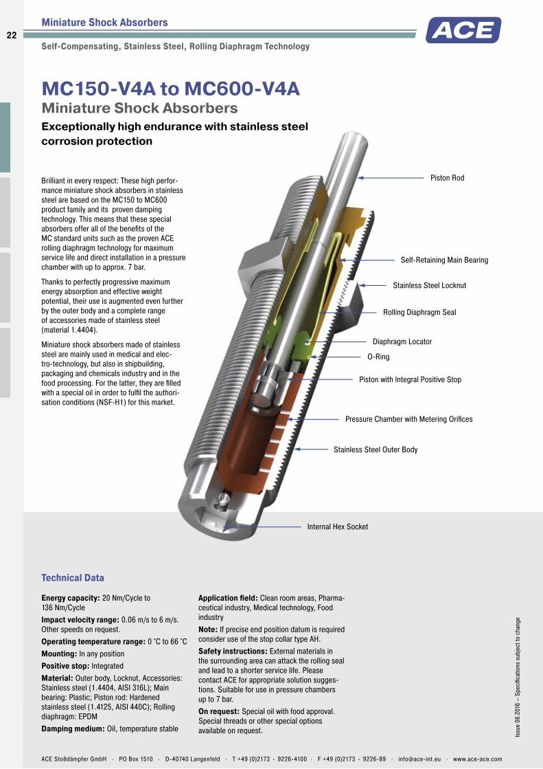
Piston Rod
Rolling Diaphragm Seal
Stainless Steel Locknut
Self-Retaining Main Bearing
Stainless Steel Outer Body
Diaphragm Locator
O-Ring
Piston with Integral Positive Stop
Pressure Chamber with Metering Orifices
Internal Hex Socket
Technical Data
Brilliant in every respect: These high perfor-mance miniature shock absorbers in stainless steel are based on the MC150 to MC600 product family and its proven damping technology. This means that these special absorbers offer all of the benefi ts of the MC standard units such as the proven ACE rolling diaphragm technology for maximum service life and direct installation in a pressure chamber with up to approx. 7 bar.
Thanks to perfectly progressive maximum energy absorption and effective weight potential, their use is augmented even further by the outer body and a complete range of accessories made of stainless steel (material 1.4404).
Miniature shock absorbers made of stainless steel are mainly used in medical and elec-tro-technology, but also in shipbuilding, packaging and chemicals industry and in the food processing. For the latter, they are fi lled with a special oil in order to fulfi l the authori-sation conditions (NSF-H1) for this market.
MC150-V4A to MC600-V4AMiniature Shock Absorbers Exceptionally high endurance with stainless steel corrosion protection
Miniature Shock Absorbers
Self-Compensating, Stainless Steel, Rolling Diaphragm Technology
Energy capacity: 20 Nm/Cycle to 136 Nm/CycleImpact velocity range: 0.06 m/s to 6 m/s. Other speeds on request.Operating temperature range: 0 °C to 66 °CMounting: In any positionPositive stop: IntegratedMaterial: Outer body, Locknut, Accessories: Stainless steel (1.4404, AISI 316L); Main bearing: Plastic; Piston rod: Hardened stainless steel (1.4125, AISI 440C); Rolling diaphragm: EPDMDamping medium: Oil, temperature stable
Application fi eld: Clean room areas, Pharma-ceutical industry, Medical technology, Food industryNote: If precise end position datum is required consider use of the stop collar type AH.Safety instructions: External materials in the surrounding area can attack the rolling seal and lead to a shorter service life. Please contact ACE for appropriate solution sugges-tions. Suitable for use in pressure chambers up to 7 bar.On request: Special oil with food approval. Special threads or other special options available on request.
22
Issu
e 08
.201
6 –
Spec
ifi ca
tions
sub
ject
to c
hang
e
ACE Stoßdämpfer GmbH . PO Box 1510 . D-40740 Langenfeld . T +49 (0)2173 - 9226-4100 . F +49 (0)2173 - 9226-89 . [email protected] . www.ace-ace.com

Piston Rod
Rolling Diaphragm Seal
Stainless Steel Locknut
Self-Retaining Main Bearing
Stainless Steel Outer Body
Diaphragm Locator
O-Ring
Piston with Integral Positive Stop
Pressure Chamber with Metering Orifices
Internal Hex Socket
Miniature Shock Absorbers MC150-V4A to MC600-V4A
Self-Compensating, Stainless Steel, Rolling Diaphragm Technology
M14x1.57.2 6 AF17 12.7Stroke
4.8
69.1 17.5AF6
Ø
MC150EUM-V4A
KM14-V4A Locknut
M14x1.5
6 AF17
MB14SC2-V4A Mounting Block
32
20
4.5
M14x1.5
M520
12
AH14-V4A Stop Collar
M14x1.517
20 12
14Ø
Ø
AF15
PP150 Nylon Button
12
4.79.4
4.8Ø
Ø
W3 max = 14 Nm
M20x1.57.2 8 AF23 12.7Stroke
6.3
79.2 17.5AF8
Ø
MC225EUM-V4A
KM20-V4A Locknut
M20x1.5
8 AF23
MB20SC2-V4A Mounting Block
50
25
13
M20x1.5
M834
20
AH20-V4A Stop Collar
M20x1.524,8
25 1220.5Ø
Ø
AF22
PP225 Nylon Button
17
3.98.8
6.3Ø
Ø
W3 max = 33 Nm
M25x1.57.3 10 AF30 25.4Stroke
8
110.3 30.9AF10
Ø
MC600EUM-V4A
KM25-V4A Locknut
M25x1.5
10 AF30
MB25SC2-V4A Mounting Block
52
32
11
M25x1.5
M836
25
AH25-V4A Stop Collar
M25x1.530
32 16
25Ø
Ø
AF27
PP600 Nylon Button
23
5.410.6
8ØØ
W3 max = 68 Nm
PerformanceMax. Energy Capacity Effective Weight
TYPESW3
Nm/cycleW4
Nm/hme min.
kgme max.
kgReturn force min.
NReturn force max.
NReturn time
s
1 Side Load Angle max.
°Weight
kgMC150EUM-V4A 20 34,000 0.9 10 3 5 0.4 4 0.06MC150EUMH-V4A 20 34,000 8.6 86 3 5 0.4 4 0.06MC150EUMH2-V4A 20 34,000 70.0 200 3 5 0.4 4 0.06MC150EUMH3-V4A 20 34,000 181.0 408 3 5 1.0 4 0.06MC225EUM-V4A 41 45,000 2.3 25 4 6 0.3 4 0.15MC225EUMH-V4A 41 45,000 23.0 230 4 6 0.3 4 0.15MC225EUMH2-V4A 41 45,000 180.0 910 4 6 0.3 4 0.15MC225EUMH3-V4A 41 45,000 816.0 1,814 4 6 0.3 4 0.15MC600EUM-V4A 136 68,000 9.0 136 5 9 0.6 2 0.26MC600EUMH-V4A 136 68,000 113.0 1,130 5 9 0.6 2 0.26MC600EUMH2-V4A 136 68,000 400.0 2,300 5 9 0.6 2 0.26MC600EUMH3-V4A 136 68,000 2,177.0 4,536 5 9 0.6 2 0.26
1 For applications with higher side load angles please contact ACE.
Additional accessories, mounting, installation ... see from page 36.
23Is
sue
08.2
016
– Sp
ecifi
catio
ns s
ubje
ct to
cha
nge
ACE Stoßdämpfer GmbH . PO Box 1510 . D-40740 Langenfeld . T +49 (0)2173 - 9226-4100 . F +49 (0)2173 - 9226-89 . [email protected] . www.ace-ace.com
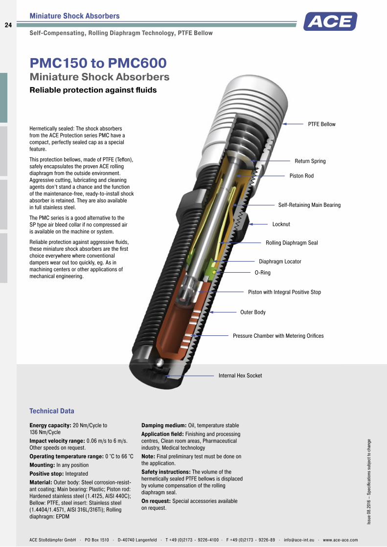
PTFE Bellow
Rolling Diaphragm Seal
Locknut
Return Spring
Outer Body
Diaphragm Locator
O-Ring
Piston with Integral Positive Stop
Pressure Chamber with Metering Orifices
Internal Hex Socket
Self-Retaining Main Bearing
Piston Rod
Technical Data
Hermetically sealed: The shock absorbers from the ACE Protection series PMC have a compact, perfectly sealed cap as a special feature.
This protection bellows, made of PTFE (Tefl on), safely encapsulates the proven ACE rolling diaphragm from the outside environment. Aggressive cutting, lubricating and cleaning agents don‘t stand a chance and the function of the maintenance-free, ready-to-install shock absorber is retained. They are also available in full stainless steel.
The PMC series is a good alternative to the SP type air bleed collar if no compressed air is available on the machine or system.
Reliable protection against aggressive fl uids, these miniature shock absorbers are the fi rst choice everywhere where conventional dampers wear out too quickly, eg. As in machining centers or other applications of mechanical engineering.
PMC150 to PMC600Miniature Shock Absorbers Reliable protection against fl uids
Miniature Shock Absorbers
Self-Compensating, Rolling Diaphragm Technology, PTFE Bellow
Energy capacity: 20 Nm/Cycle to 136 Nm/CycleImpact velocity range: 0.06 m/s to 6 m/s. Other speeds on request.Operating temperature range: 0 °C to 66 °CMounting: In any positionPositive stop: IntegratedMaterial: Outer body: Steel corrosion-resist-ant coating; Main bearing: Plastic; Piston rod: Hardened stainless steel (1.4125, AISI 440C); Bellow: PTFE, steel insert: Stainless steel (1.4404/1.4571, AISI 316L/316Ti); Rolling diaphragm: EPDM
Damping medium: Oil, temperature stableApplication fi eld: Finishing and processing centres, Clean room areas, Pharmaceutical industry, Medical technologyNote: Final preliminary test must be done on the application.Safety instructions: The volume of the hermetically sealed PTFE bellows is displaced by volume compensation of the rolling diaphragm seal.On request: Special accessories available on request.
24
Issu
e 08
.201
6 –
Spec
ifi ca
tions
sub
ject
to c
hang
e
ACE Stoßdämpfer GmbH . PO Box 1510 . D-40740 Langenfeld . T +49 (0)2173 - 9226-4100 . F +49 (0)2173 - 9226-89 . [email protected] . www.ace-ace.com

PTFE Bellow
Rolling Diaphragm Seal
Locknut
Return Spring
Outer Body
Diaphragm Locator
O-Ring
Piston with Integral Positive Stop
Pressure Chamber with Metering Orifices
Internal Hex Socket
Self-Retaining Main Bearing
Piston Rod
Miniature Shock Absorbers PMC150 to PMC600
Self-Compensating, Rolling Diaphragm Technology, PTFE Bellow
98 ± 237.5
7.2
M14x1.5
AF6
Ø 20
Stroke12.56AF17
PMC150EUM
MB14 Clamp Mount
32
20
4.5
M14x1.5
M520
12
RF14 Rectangular Flange
34
20
6M14x1.5
26
M5x12
KM14 Locknut
M14x1.5
6 AF17
108 ± 237.2
7.2
M20x1.5
AF8
Ø 25
Stroke12.5
8AF23
PMC225EUM
MB20 Clamp Mount
40
25
6
M20x1.5
M628
20
RF20 Rectangular Flange
46
32
8M20x1.5
36
M6x14
KM20 Locknut
M20x1.5
8 AF23
155 ± 255.3
7.3
M25x1.5
AF10
Ø 30
Stroke25.4
10AF30
PMC600EUM
MB25 Clamp Mount
46
32
6
M25x1.5
M634
25
RF25 Rectangular Flange
52
32
8M25x1.5
42
M6x14
KM25 Locknut
M25x1.5
10 AF30
Additional accessories, mounting, installation ... see from page 36.
PerformanceMax. Energy Capacity Effective Weight
TYPESW3
Nm/cycleW4
Nm/hme min.
kgme max.
kgReturn force min.
NReturn force max.
NReturn time
s
Side Load Angle max.
°Weight
kgPMC150EUM 20 34,000 0.9 10 5 60 0.4 4 0.08PMC150EUMH 20 34,000 8.6 86 5 60 0.4 4 0.08PMC150EUMH2 20 34,000 70.0 200 5 60 0.4 4 0.08PMC150EUMH3 20 34,000 181.0 408 5 60 1.0 4 0.08PMC225EUM 41 45,000 2.3 25 5 65 0.3 4 0.17PMC225EUMH 41 45,000 23.0 230 5 65 0.3 4 0.17PMC225EUMH2 41 45,000 180.0 910 5 65 0.3 4 0.17PMC225EUMH3 41 45,000 816.0 1,814 5 65 0.3 4 0.17PMC600EUM 136 68,000 9.0 136 5 85 0.6 2 0.32PMC600EUMH 136 68,000 113.0 1,130 5 85 0.6 2 0.32PMC600EUMH2 136 68,000 400.0 2,300 5 85 0.6 2 0.32PMC600EUMH3 136 68,000 2,177.0 4,536 5 85 0.6 2 0.32
25Is
sue
08.2
016
– Sp
ecifi
catio
ns s
ubje
ct to
cha
nge
ACE Stoßdämpfer GmbH . PO Box 1510 . D-40740 Langenfeld . T +49 (0)2173 - 9226-4100 . F +49 (0)2173 - 9226-89 . [email protected] . www.ace-ace.com

PTFE Bellow
Rolling Diaphragm Seal
Stainless Steel Locknut
Return Spring
Stainless Steel Outer Body
Diaphragm Locator
O-Ring
Piston with Integral Positive Stop
Pressure Chamber with Metering Orifices
Internal Hex Socket
Self-Retaining Main Bearing
Piston Rod
Technical Data
Hermetically sealed and rustproof: The Protec-tion series PMC is also available in a stainless steel design. This is or particular interest to the food and packaging industries.
Their main special feature is the compact, totally sealed bellow between the body and the cap made of PTFE (Tefl on). This protection safely encapsulates the ACE rolling diaphragm from the outside environment. Aggressive fl uids don‘t stand a chance. The PMC series is an excellent alternative if the accessory option of the SP type air bleed collar cannot be used due to a lack of compressed air.
The PMC series miniature shock absorbers, produced from stainless steel, are primarily suitable for use in the food industry, but are also wherever an elegant look is important e.g. in shipbuilding.
PMC150-V4A to PMC600-V4AMiniature Shock Absorbers Optimum corrosion protection
Miniature Shock Absorbers
Self-Compensating, Stainless Steel, Rolling Diaphragm Technology, PTFE Bellow
Energy capacity: 20 Nm/Cycle to 136 Nm/CycleImpact velocity range: 0.06 m/s to 6 m/s. Other speeds on request.Operating temperature range: 0 °C to 66 °CMounting: In any positionPositive stop: IntegratedMaterial: Outer body: Stainless steel (1.4404, AISI 316L); Main bearing: Plastic; Piston rod: Hardened stainless steel (1.4125, AISI 440C); Bellow: PTFE, steel insert: Stainless steel (1.4404/1.4571, AISI 316L/316Ti); Rolling diaphragm: EPDM
Damping medium: Oil, temperature stableApplication fi eld: Finishing and processing centres, Clean room areas, Pharmaceutical industry, Medical technologyNote: Final preliminary test must be done on the application.Safety instructions: The volume of the hermetically sealed PTFE bellows is displaced by volume compensation of the rolling diaphragm seal.On request: Special accessories available on request.
26
Issu
e 08
.201
6 –
Spec
ifi ca
tions
sub
ject
to c
hang
e
ACE Stoßdämpfer GmbH . PO Box 1510 . D-40740 Langenfeld . T +49 (0)2173 - 9226-4100 . F +49 (0)2173 - 9226-89 . [email protected] . www.ace-ace.com

PTFE Bellow
Rolling Diaphragm Seal
Stainless Steel Locknut
Return Spring
Stainless Steel Outer Body
Diaphragm Locator
O-Ring
Piston with Integral Positive Stop
Pressure Chamber with Metering Orifices
Internal Hex Socket
Self-Retaining Main Bearing
Piston Rod
Miniature Shock Absorbers PMC150-V4A to PMC600-V4A
Self-Compensating, Stainless Steel, Rolling Diaphragm Technology, PTFE Bellow
98 ± 237.5
7.2
M14x1.5
AF6
Ø 20
Stroke12.56AF17
PMC150EUM-V4A
MB14SC2-V4A Mounting Block
32
20
4.5
M14x1.5
M520
12
KM14-V4A Locknut
M14x1.5
6 AF17
108 ± 237.2
7.2
M20x1.5
AF8
Ø 25
Stroke12.5
8AF23
PMC225EUM-V4A
MB20SC2-V4A Mounting Block
50
25
13
M20x1.5
M834
20
KM20-V4A Locknut
M20x1.5
8 AF23
155 ± 255.3
7.3
M25x1.5
AF10
Ø 30
Stroke25.4
10AF30
PMC600EUM-V4A
MB25SC2-V4A Mounting Block
52
32
11
M25x1.5
M836
25
KM25-V4A Locknut
M25x1.5
10 AF30
PerformanceMax. Energy Capacity Effective Weight
TYPESW3
Nm/cycleW4
Nm/hme min.
kgme max.
kg
Return force min.
N
Return force max.
NReturn time
s
Side Load Angle max.
°Weight
kgPMC150EUM-V4A 20 34,000 0.9 10 5 60 0.4 4 0.08PMC150EUMH-V4A 20 34,000 8.6 86 5 60 0.4 4 0.08PMC150EUMH2-V4A 20 34,000 70.0 200 5 60 0.4 4 0.08PMC150EUMH3-V4A 20 34,000 181.0 408 5 60 1.0 4 0,08PMC225EUM-V4A 41 45,000 2.3 25 5 65 0.3 4 0.17PMC225EUMH-V4A 41 45,000 23.0 230 5 65 0.3 4 0.17PMC225EUMH2-V4A 41 45,000 180.0 910 5 65 0.3 4 0.17PMC225EUMH3-V4A 41 45,000 816.0 1,814 5 65 0.3 4 0.17PMC600EUM-V4A 136 68,000 9.0 136 5 85 0.6 2 0.32PMC600EUMH-V4A 136 68,000 113.0 1,130 5 85 0.6 2 0.32PMC600EUMH2-V4A 136 68,000 400.0 2,300 5 85 0.6 2 0.32PMC600EUMH3-V4A 136 68,000 2,177.0 4,536 5 85 0.6 2 0.32
Additional accessories, mounting, installation ... see from page 36.
27Is
sue
08.2
016
– Sp
ecifi
catio
ns s
ubje
ct to
cha
nge
ACE Stoßdämpfer GmbH . PO Box 1510 . D-40740 Langenfeld . T +49 (0)2173 - 9226-4100 . F +49 (0)2173 - 9226-89 . [email protected] . www.ace-ace.com

Piston Rod
Locknut
Outer Body
Piston
Pressure Chamber with Metering Orifices
Rod Button
Accumulator
Seals
Positive Stop
Main Bearing
Check Valve
Return Spring
Technical Data
Ideal for soft damping: The SC found in the model code from the ACE series SC190 to 925 stands for ‘soft contact’. These miniature shock absorbers manufactured from one solid piece are designed in such a way that they can be setup with a linear or a progressive braking curve. The soft damping character is thanks to the special, long strokes producing smooth deceleration and low reaction forces.
These maintenance-free, ready-to-install hydraulic machine elements are equipped with an integrated positive stop. The use of side load adapter allows impact angles of up to 25°. Thanks to the designed overlapping effective weight ranges, these dampers cover an effective load range of below 1 kg to more than 2,000 kg!
The miniature shock absorbers from the SC190 to 925 series are used in mechanical engineering and primarily in the areas of handling and automation.
SC190 to SC925Miniature Shock Absorbers Long stroke and soft impact
Miniature Shock Absorbers
Self-Compensating, Soft-Contact
Energy capacity: 25 Nm/Cycle to 110 Nm/CycleImpact velocity range: 0.15 m/s to 3.66 m/s. Other speeds on request.Operating temperature range: 0 °C to 66 °CMounting: In any positionPositive stop: IntegratedMaterial: Outer body, Accessories: Steel corrosion-resistant coating; Piston rod: Hardened stainless steelDamping medium: Oil, temperature stable
Application fi eld: Linear slides, Pneumatic cylinders, Handling modules, Machines and plantsNote: If precise end position datum is required consider use of the stop collar type AH.Safety instructions: External materials in the surrounding area can attack the seal compo-nents and lead to a shorter service life. Please contact ACE for appropriate solution sugges-tions. Do not paint the shock absorbers due to heat emission.
On request: Nickel-plated or weartec fi nish (seawater resistant) or other special fi nishes available to special order. Models without rod end button.
28
Issu
e 08
.201
6 –
Spec
ifi ca
tions
sub
ject
to c
hang
e
ACE Stoßdämpfer GmbH . PO Box 1510 . D-40740 Langenfeld . T +49 (0)2173 - 9226-4100 . F +49 (0)2173 - 9226-89 . [email protected] . www.ace-ace.com
Piston Rod
Locknut
Outer Body
Piston
Pressure Chamber with Metering Orifices
Rod Button
Accumulator
Seals
Positive Stop
Main Bearing
Check Valve
Return Spring
Miniature Shock Absorbers SC190 to SC925
Self-Compensating, Soft-Contact
44.6
12M14x1.57 AF12 687.3
AF17 1627
Stroke4
Ø
Ø
SC190EUM; 0 to 4
M14x1 and M16x1 also available to special order
MB14 Clamp Mount
32
20
4.5
M14x1.5
M520
12
RF14 Rectangular Flange
34
20
6M14x1.5
26
M5x12
4.84.6
17M20x1.57 AF18 887.4
AF23 1930
Stroke1.7Ø
Ø
SC300EUM; 0 to 4
M22x1.5 also available to special order
MB20 Clamp Mount
40
25
6
M20x1.5
M628
20
RF20 Rectangular Flange
46
32
8M20x1.5
36
M6x14
6.34.6
23M25x1.57 AF23 10106.4
AF30 25.436.3
Stroke2Ø
Ø
SC650EUM; 0 to 4
M26x1.5 also available to special order
MB25 Clamp Mount
46
32
6
M25x1.5
M634
25
RF25 Rectangular Flange
52
32
8M25x1.5
42
M6x14
6.34.6
23M25x1.57 AF23 10138
AF30 4051
Stroke2Ø
Ø
SC925EUM; 0 to 4
MB25 Clamp Mount
46
32
6
M25x1.5
M634
25
RF25 Rectangular Flange
52
32
8M25x1.5
42
M6x14
Additional accessories, mounting, installation ... see from page 36.
PerformanceMax. Energy Capacity Effective Weight
Soft-Contact Self-Compensating
TYPESW3
Nm/cycleW4
Nm/hme min.
kgme max.
kgme min.
kgme max.
kgHardness
Return force min.
N
Return force max.
NReturn time
s
1 Side Load Angle max.
°Weight
kgSC190EUM-0 25 34,000 - - 0.7 4 -0 4 9 0.25 5 0.08SC190EUM-1 25 34,000 2.3 6 1.4 7 -1 4 9 0.25 5 0.08SC190EUM-2 25 34,000 5.5 16 3.6 18 -2 4 9 0.25 5 0.08SC190EUM-3 25 34,000 14 41 9.0 45 -3 4 9 0.25 5 0.08SC190EUM-4 25 34,000 34 91 23.0 102 -4 4 9 0.25 5 0.08SC300EUM-0 33 45,000 - - 0.7 4 -0 5 10 0.10 5 0.11SC300EUM-1 33 45,000 2.3 7 1.4 8 -1 5 10 0.10 5 0.11SC300EUM-2 33 45,000 7 23 4.5 27 -2 5 10 0.10 5 0.11SC300EUM-3 33 45,000 23 68 14.0 82 -3 5 10 0.10 5 0.11SC300EUM-4 33 45,000 68 181 32.0 204 -4 5 10 0.10 5 0.11SC650EUM-0 73 68,000 - - 2.3 14 -0 11 32 0.20 5 0.31SC650EUM-1 73 68,000 11 36 8.0 45 -1 11 32 0.20 5 0.31SC650EUM-2 73 68,000 34 113 23.0 136 -2 11 32 0.20 5 0.31SC650EUM-3 73 68,000 109 363 68.0 408 -3 11 32 0.20 5 0.31SC650EUM-4 73 68,000 363 1,089 204.0 1,180 -4 11 32 0.20 5 0.31SC925EUM-0 110 90,000 8 25 4.5 29 -0 11 32 0.40 5 0.39SC925EUM-1 110 90,000 22 72 14.0 90 -1 11 32 0.40 5 0.39SC925EUM-2 110 90,000 59 208 40.0 227 -2 11 32 0.40 5 0.39SC925EUM-3 110 90,000 181 612 113.0 726 -3 11 32 0.40 5 0.39SC925EUM-4 110 90,000 544 1,952 340.0 2,088 -4 11 32 0.40 5 0.39
1 For applications with higher side load angles consider using the side load adaptor (BV) pages 38 to 45.
29Is
sue
08.2
016
– Sp
ecifi
catio
ns s
ubje
ct to
cha
nge
ACE Stoßdämpfer GmbH . PO Box 1510 . D-40740 Langenfeld . T +49 (0)2173 - 9226-4100 . F +49 (0)2173 - 9226-89 . [email protected] . www.ace-ace.com
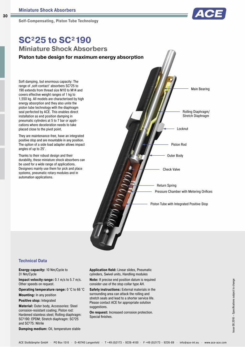
Rolling Diaphragm/Stretch Diaphragm
Locknut
Outer Body
Piston Tube with Integrated Positive Stop
Pressure Chamber with Metering Orifices
Main Bearing
Check Valve
Return Spring
Piston Rod
Technical Data
Soft damping, but enormous capacity: The range of ‚soft contact‘ absorbers SC²25 to 190 extends from thread size M10 to M14 and covers effective weight ranges of 1 kg to 1,550 kg. All models are characterised by high energy absorption and they also unite the piston tube technology with the diaphragm seal perfected by ACE. This enables direct installation as end position damping in pneumatic cylinders at 5 to 7 bar or appli-cations where deceleration needs to take placed close to the pivot point.
They are maintenance-free, have an integrated positive stop and are mountable in any position. The option of a side load adapter allows impact angles of up to 25°.
Thanks to their robust design and their durability, these miniature shock absorbers can be used for a wide range of applications. Designers mainly use them for pick and place systems, pneumatic rotary modules and in automation applications.
SC²25 to SC²190Miniature Shock Absorbers Piston tube design for maximum energy absorption
Miniature Shock Absorbers
Self-Compensating, Piston Tube Technology
Energy capacity: 10 Nm/Cycle to 31 Nm/CycleImpact velocity range: 0.1 m/s to 5.7 m/s. Other speeds on request.Operating temperature range: 0 °C to 66 °CMounting: In any positionPositive stop: IntegratedMaterial: Outer body, Accessories: Steel corrosion-resistant coating; Piston rod: Hardened stainless steel; Rolling diaphragm: SC²190: EPDM; Stretch diaphragm: SC²25 and SC²75: NitrileDamping medium: Oil, temperature stable
Application fi eld: Linear slides, Pneumatic cylinders, Swivel units, Handling modulesNote: If precise end position datum is required consider use of the stop collar type AH.Safety instructions: External materials in the surrounding area can attack the rolling and stretch seals and lead to a shorter service life. Please contact ACE for appropriate solution suggestions.On request: Increased corrosion protection. Special fi nishes.
30
Issu
e 08
.201
6 –
Spec
ifi ca
tions
sub
ject
to c
hang
e
ACE Stoßdämpfer GmbH . PO Box 1510 . D-40740 Langenfeld . T +49 (0)2173 - 9226-4100 . F +49 (0)2173 - 9226-89 . [email protected] . www.ace-ace.com
Rolling Diaphragm/Stretch Diaphragm
Locknut
Outer Body
Piston Tube with Integrated Positive Stop
Pressure Chamber with Metering Orifices
Main Bearing
Check Valve
Return Spring
Piston Rod
Miniature Shock Absorbers SC²25 to SC²190
Self-Compensating, Piston Tube Technology
3.15
M10x15 AF7 472
AF12 811
StrokeØ
SC25EUM; 5 to 7
MB10SC2 Mounting Block
25
14
3.5
M10x1
M4
16
10
RF10 Rectangular Flange
28
14
6M10x1
20
M4x10
4
M12x15.9 AF8 578
AF14 1014
StrokeØ
SC75EUM; 5 to 7
MB12SC2 Mounting Block
32
16
4.5
M12x1
M5
20
12
RF12 Rectangular Flange
32
20
6M12x1
24
M5x12
4.8
M14x1.55 AF10 677
AF17 1217
StrokeØ
SC190EUM; 5 to 7
M14x1 also available to special order
MB14SC2 Mounting Block
32
20
4.5
M14x1.5
M520
12
RF14 Rectangular Flange
34
20
6M14x1.5
26
M5x12
Additional accessories, mounting, installation ... see from page 36.
PerformanceMax. Energy Capacity Effective Weight
TYPESW3
Nm/cycleW4
Nm/hme min.
kgme max.
kgHardness Return force min.
NReturn force max.
NReturn time
s
1 Side Load Angle max.
°Weight
kgSC25EUM-5 10 16,000 1 5 -5 4.5 14 0.3 2 0.027SC25EUM-6 10 16,000 4 44 -6 4.5 14 0.3 2 0.027SC25EUM-7 10 16,000 42 500 -7 4.5 14 0.3 2 0.027SC75EUM-5 16 30,000 1 8 -5 6.0 19 0.3 2 0.045SC75EUM-6 16 30,000 7 78 -6 6.0 19 0.3 2 0.045SC75EUM-7 16 30,000 75 800 -7 6.0 19 0.3 2 0.045SC190EUM-5 31 50,000 2 16 -5 6.0 19 0.4 2 0.060SC190EUM-6 31 50,000 13 140 -6 6.0 19 0.4 2 0.060SC190EUM-7 31 50,000 136 1,550 -7 6.0 19 0.4 2 0.060
1 For applications with higher side load angles consider using the side load adaptor (BV) pages 38 to 45.
31Is
sue
08.2
016
– Sp
ecifi
catio
ns s
ubje
ct to
cha
nge
ACE Stoßdämpfer GmbH . PO Box 1510 . D-40740 Langenfeld . T +49 (0)2173 - 9226-4100 . F +49 (0)2173 - 9226-89 . [email protected] . www.ace-ace.com

Membrane Accumulator
Locknut
Outer Body
Pressure Chamber with Metering Orifices
Piston Tube
Rod Seals
Piston Check Valve
Return Spring
Piston Rod
Rod Button
Positive Stop
Main Bearing
Technical Data
Added safety with accumulator technology: The larger ‚soft contact‘ models from the SC²300 to 650 are available with up to three times the energy absorption compaired to similar sizes of standard shock absorbers SC190 to 925, due to the ACE piston tube speciality. Furthermore, the membrane accumulator serves as a compensation element for the oil displaced in the shock absorber and replaces the standard use of absorber materials. This increases process safety even further.
The absorbers, which are perfect for rotary modules for example, are available in progressively stepped effective weight ranges with an integrated positive stop. They are maintenance-free and ready for direct installation. The side load adapter option allows impact angles of up to 25°.
These miniature shock absorbers offer high performance levels with a long service life and are particularly popular for handling, mounting very close to pivots and automation tasks.
SC²300 to SC²650Miniature Shock Absorbers Piston tube design for maximum energy absorption
Miniature Shock Absorbers
Self-Compensating, Piston Tube Technology
Energy capacity: 73 Nm/Cycle to 210 Nm/CycleImpact velocity range: 0.09 m/s to 3.66 m/s. Other speeds on request.Operating temperature range: 0 °C to 66 °CMounting: In any positionPositive stop: IntegratedMaterial: Outer body: Steel corrosion-resistant coating; Piston rod: Hardened stainless steel; Accessories: Hardened steel and corrosion-resistant coatingDamping medium: Oil, temperature stable
Application fi eld: Turntables, Swivel units, Robot arms, Linear slidesNote: If precise end position datum is required consider use of the stop collar type AH.On request: Increased corrosion protection. Special fi nishes.
32
Issu
e 08
.201
6 –
Spec
ifi ca
tions
sub
ject
to c
hang
e
ACE Stoßdämpfer GmbH . PO Box 1510 . D-40740 Langenfeld . T +49 (0)2173 - 9226-4100 . F +49 (0)2173 - 9226-89 . [email protected] . www.ace-ace.com

Membrane Accumulator
Locknut
Outer Body
Pressure Chamber with Metering Orifices
Piston Tube
Rod Seals
Piston Check Valve
Return Spring
Piston Rod
Rod Button
Positive Stop
Main Bearing
Miniature Shock Absorbers SC²300 to SC²650
Self-Compensating, Piston Tube Technology
4.617M20x1.57 AF18 8
79.5AF23 15
26
Stroke6.3
1.8Ø
Ø
SC300EUM; 5 to 9
MB20SC2 Mounting Block
50
25
13
M20x1.5
M834
20
RF20 Rectangular Flange
46
32
8M20x1.5
36
M6x14
4.623M25x1.57 AF23 10
106AF30 23
34
Stroke9.6
1.8Ø
Ø
SC650EUM; 5 to 9
MB25SC2 Mounting Block
52
32
11
M25x1.5
M836
25
RF25 Rectangular Flange
52
32
8M25x1.5
42
M6x14
Additional accessories, mounting, installation ... see from page 36.
PerformanceMax. Energy Capacity Effective Weight
TYPESW3
Nm/cycleW4
Nm/hme min.
kgme max.
kgHardness Return force min.
NReturn force max.
NReturn time
s
1 Side Load Angle max.
°Weight
kgSC300EUM-5 73 45,000 11 45 -5 8 18 0.2 5 0,164SC300EUM-6 73 45,000 34 136 -6 8 18 0.2 5 0.164SC300EUM-7 73 45,000 91 181 -7 8 18 0.2 5 0.164SC300EUM-8 73 45,000 135 680 -8 8 18 0.2 5 0.164SC300EUM-9 73 45,000 320 1,950 -9 8 18 0.2 5 0.164SC650EUM-5 210 68,000 23 113 -5 11 33 0.3 5 0.340SC650EUM-6 210 68,000 90 360 -6 11 33 0.3 5 0.340SC650EUM-7 210 68,000 320 1,090 -7 11 33 0.3 5 0.340SC650EUM-8 210 68,000 770 2,630 -8 11 33 0.3 5 0.340SC650EUM-9 210 68,000 1,800 6,350 -9 11 33 0.3 5 0.340
1 For applications with higher side load angles consider using the side load adaptor (BV) pages 38 to 45.
33Is
sue
08.2
016
– Sp
ecifi
catio
ns s
ubje
ct to
cha
nge
ACE Stoßdämpfer GmbH . PO Box 1510 . D-40740 Langenfeld . T +49 (0)2173 - 9226-4100 . F +49 (0)2173 - 9226-89 . [email protected] . www.ace-ace.com

Accumulator
Piston Rod
Rod Button
Locknut
Main Bearing
Seals
Positive Stop
Outer Body
Piston
Check Valve
Return Spring
Pressure Chamber with Metering Orifices
Adjustment Segment
Adjustment Chamber
Technical Data
Exact adjustment: The miniature shock absorbers from the MA30 to 900 series can be adjusted and precisely adapted to your requirements. For example, the MA150 displays the rolling diaphragm technology from the MC150 to 600 series and offers all of the advantages of this technology, such as use in pressure chambers. Thanks to long strokes (including 40 mm on the MA900) lower reaction forces result, which provide a soft damping characteristic.
All variations of these units are maintenance-free, ready-to-install machine elements and have an integrated positive stop. They provide the best service where application data changes, where the calculation parameters are not clear or where maximum fl exibility in the possible usage is required.
The adjustable miniature shock absorbers from ACE can be used to meet precisly the customer‘s application and are therefore found everywhere in mechanical engineering and many other applications.
MA30 to MA900Miniature Shock Absorbers Stepless adjustment
Miniature Shock Absorbers
Adjustable
Energy capacity: 3.5 Nm/Cycle to 100 Nm/CycleImpact velocity range: 0.15 m/s to 4.5 m/s. Other speeds on request.Operating temperature range: 0 °C to 66 °CMounting: In any positionPositive stop: IntegratedAdjustment: Hard impact at the start of stroke, adjust the ring towards 9 or PLUS. Hard impact at the end of stroke, adjust the ring towards 0 or MINUS.
Material: Outer body, Accessories: Steel corrosion-resistant coating; Piston rod: Hardened stainless steelDamping medium: Oil, temperature stableApplication fi eld: Linear slides, Pneumatic cylinders, Swivel units, Handling modulesNote: If precise end position datum is required consider use of the stop collar type AH. Shock absorber is preset at delivery in a neutral position between hard and soft.Safety instructions: External materials in the surrounding area can attack the rolling diaphragm seal and lead to a shorter service
life. Please contact ACE for appropriate solution suggestions.On request: Nickel-plated or other special options available to special order. Models without rod end button.
34
Issu
e 08
.201
6 –
Spec
ifi ca
tions
sub
ject
to c
hang
e
ACE Stoßdämpfer GmbH . PO Box 1510 . D-40740 Langenfeld . T +49 (0)2173 - 9226-4100 . F +49 (0)2173 - 9226-89 . [email protected] . www.ace-ace.com

Accumulator
Piston Rod
Rod Button
Locknut
Main Bearing
Seals
Positive Stop
Outer Body
Piston
Check Valve
Return Spring
Pressure Chamber with Metering Orifices
Adjustment Segment
Adjustment Chamber
Miniature Shock Absorbers MA30 to MA900
Adjustable
3 StrokeAF10848.3 13.1
2.56.4M8x14.1
Adjustment Screw
2.1
2.5 ØØ
MA30EUM
MB8SC2 Mounting Block
25
12
3.5
M8x1
M4
16
10
RF8 Rectangular Flange
25
14
6M8x1
18
M4x10
4 StrokeAF127.249.8 14.9
3.27.7M10x15.1
Adjustment Screw
3
2.5 ØØ
MA50EUM
MB10SC2 Mounting Block
25
14
3.5
M10x1
M4
16
10
RF10 Rectangular Flange
28
14
6M10x1
20
M4x10
5 StrokeAF1410.265.7 18.2
3.27.7M12x15
Adjustment Screw
3
2.5 ØØ
MA35EUM
MB12 Clamp Mount
32
16
4.5
M12x1
M5
20
12
RF12 Rectangular Flange
32
20
6M12x1
24
M5x12
4.84.7
12M14x1.57.1 AF12 6
69.1
AF17 12.722.5
Stroke
Adjustment Screw
Ø
Ø
MA150EUM
M14x1 also available to special order
MB14 Clamp Mount
32
20
4.5
M14x1.5
M520
12
RF14 Rectangular Flange
34
20
6M14x1.5
26
M5x12
4.84.6
17M20x1.513.5 8
88.619
30
StrokeAF23
4.8AF18
Ø
Ø
Adjustment KnobMA225EUM
MB20 Clamp Mount
40
25
6
M20x1.5
M628
20
RF20 Rectangular Flange
46
32
8M20x1.5
36
M6x14
6.34.6
23M25x1.517 10
106.1 (137.8)25.4 (40)
36.3 (50.9)
StrokeAF30
5AF23
Ø
Ø
Adjustment KnobMA600EUM
Dimensions for MA900EUM in ( ). MA600EUML with M27x3 available to special order
MB25 Clamp Mount
46
32
6
M25x1.5
M634
25
RF25 Rectangular Flange
52
32
8M25x1.5
42
M6x14
Additional accessories, mounting, installation ... see from page 36.
PerformanceMax. Energy Capacity Effective Weight
TYPESW3
Nm/cycleW4
Nm/hme min.
kgme max.
kgReturn force min.
NReturn force max.
NReturn time
s
1 Side Load Angle max.
°Weight
kgMA30EUM 3.5 5,650 0.23 15 1.7 5.3 0.3 2.0 0.013MA50EUM 5.5 13,550 4.50 20 3.0 6.0 0.3 2.0 0.025MA35EUM 4.0 6,000 6.00 57 5.0 11.0 0.2 2.0 0.043MA150EUM 22.0 35,000 1.00 109 3.0 5.0 0.4 2.0 0.060MA225EUM 25.0 45,000 2.30 226 5.0 10.0 0.1 2.0 0.130MA600EUM 68.0 68,000 9.00 1,360 10.0 30.0 0.2 2.0 0.310MA900EUM 100.0 90,000 14.00 2,040 10.0 35.0 0.4 1.0 0,400
1 For applications with higher side load angles consider using the side load adaptor (BV) pages 38 to 45.
35Is
sue
08.2
016
– Sp
ecifi
catio
ns s
ubje
ct to
cha
nge
ACE Stoßdämpfer GmbH . PO Box 1510 . D-40740 Langenfeld . T +49 (0)2173 - 9226-4100 . F +49 (0)2173 - 9226-89 . [email protected] . www.ace-ace.com

Minature Shock Absorber Accessories M5 to M25
Selection Chart
Locknut Stop Collar Clamp Mount 1 Mounting Block Rectangular Flange Universal Mount 2 Side Load Adaptor
2 Steel Shroud Air Bleed Collar Switch Stop Collar
Steel Button Steel/Urethane Button
Nylon Button
Shock Absorber Type KM AH MB MB...SC2 RF UM BV PB SP AS PS BP PP Page
Thread M5x0.5 Thread M5x0.5MC5EUM KM5 AH5 – MB5SC2 – – – – – – – – – 38
Thread M6x0.5 Thread M6x0.5MC9EUM KM6 AH6 – MB6SC2 RF6 – – – – – – – – 38
Thread M8x1 Thread M8x1MA30EUM KM8 AH8 – MB8SC2 RF8 – BV8 PB8 – – – – – 38MC10EUM KM8 AH8 – MB8SC2 RF8 – BV8A PB8-A – – – – – 38MC30EUM KM8 AH8 – MB8SC2 RF8 – BV8 PB8 – – – – – 38
Thread M10x1 Thread M10x1MA50EUM KM10 AH10 – MB10SC2 RF10 UM10 BV10 PB10 – AS10 PS10 – – 39MC25EUM KM10 AH10 – MB10SC2 RF10 UM10 BV10 PB10 – AS10 PS10 – – 39SC25EUM; 5 to 7 KM10 AH10 – MB10SC2 RF10 UM10 BV10SC PB10SC – – – – – 39
Thread M12x1 Thread M12x1MA35EUM KM12 AH12 MB12 – RF12 UM12 BV12 PB12 – AS12 PS12 – – 39MC75EUM KM12 AH12 MB12 – RF12 UM12 BV12 PB12 – AS12 PS12 – – 39SC75EUM; 5 to 7 KM12 AH12 – MB12SC2 RF12 UM12 BV12SC PB12SC SP12 AS12 PS12SC – – 39
Thread M14x1.5 Thread M14x1.5MA150EUM KM14 AH14 MB14 – RF14 UM14 BV14 PB14 SP14 AS14 PS14 – – 40MC150EUM KM14 AH14 MB14 – RF14 UM14 BV14 PB14 SP14 AS14 PS14 – PP150 40MC150EUM-V4A KM14-V4A AH14-V4A – MB14SC2-V4A – – – – – – – – PP150 40PMC150EUM KM14 – MB14 – RF14 – – – – – – – – 40PMC150EUM-V4A KM14-V4A – – MB14SC2-V4A – – – – – – – – – 40SC190EUM; 0 to 4 KM14 AH14 MB14 – RF14 UM14 BV14SC PB14SC – AS14 – BP14 – 40SC190EUM; 5 to 7 KM14 AH14 – MB14SC2 RF14 UM14 BV14 PB14 SP14 AS14 PS14 – – 40
Thread M20x1.5 Thread M20x1.5MA225EUM KM20 AH20 MB20 – RF20 UM20 BV20SC PB20SC – AS20 – BP20 – 41MC225EUM KM20 AH20 MB20 – RF20 UM20 BV20 PB20 SP20 AS20 PS20 – PP225 41MC225EUM-V4A KM20-V4A AH20-V4A – MB20SC2-V4A – – – – – – – – PP225 41PMC225EUM KM20 – MB20 – RF20 – – – – – – – – 41PMC225EUM-V4A KM20-V4A – – MB20SC2-V4A – – – – – – – – – 41SC300EUM; 0 to 4 KM20 AH20 MB20 – RF20 UM20 BV20SC PB20SC – AS20 – BP20 – 41SC300EUM; 5 to 9 KM20 AH20 – MB20SC2 RF20 UM20 BV20SC PB20SC – AS20 – – – 41
Thread M25x1.5 Thread M25x1.5MA600EUM KM25 AH25 MB25 – RF25 UM25 BV25SC PB25SC – AS25 – BP25 – 42MA900EUM KM25 AH25 MB25 – RF25 UM25 – – – AS25 – BP25 – 42MC600EUM KM25 AH25 MB25 RF25 UM25 BV25 PB25 SP25 AS25 PS25 – PP600 42MC600EUM-V4A KM25-V4A AH25-V4A – MB25SC2-V4A – – – – – – – – PP600 42PMC600EUM – – MB25 – RF25 – – – – – – – – 42PMC600EUM-V4A KM25-V4A – – MB25SC2-V4A – – – – – – – – – 42SC650EUM; 0 to 4 KM25 AH25 MB25 – RF25 UM25 BV25SC PB25SC – AS25 – – – 42
1 Use a locknut for protection if a clamp mount MB...SC2 is installed.
2 Only mountable on units without button. Remove the button from the shock absorber, if there’s one fitted!
Dimensions can be found on the corresponding accessories pages.
36
Issu
e 08
.201
6 –
Spec
ifica
tions
sub
ject
to c
hang
e
ACE Stoßdämpfer GmbH . PO Box 1510 . D-40740 Langenfeld . T +49 (0)2173 - 9226-4100 . F +49 (0)2173 - 9226-89 . [email protected] . www.ace-ace.com

Minature Shock Absorber Accessories M5 to M25
Selection Chart
Locknut Stop Collar Clamp Mount 1 Mounting Block Rectangular Flange Universal Mount 2 Side Load Adaptor
2 Steel Shroud Air Bleed Collar Switch Stop Collar
Steel Button Steel/Urethane Button
Nylon Button
Shock Absorber Type KM AH MB MB...SC2 RF UM BV PB SP AS PS BP PP Page
Thread M5x0.5 Thread M5x0.5MC5EUM KM5 AH5 – MB5SC2 – – – – – – – – – 38
Thread M6x0.5 Thread M6x0.5MC9EUM KM6 AH6 – MB6SC2 RF6 – – – – – – – – 38
Thread M8x1 Thread M8x1MA30EUM KM8 AH8 – MB8SC2 RF8 – BV8 PB8 – – – – – 38MC10EUM KM8 AH8 – MB8SC2 RF8 – BV8A PB8-A – – – – – 38MC30EUM KM8 AH8 – MB8SC2 RF8 – BV8 PB8 – – – – – 38
Thread M10x1 Thread M10x1MA50EUM KM10 AH10 – MB10SC2 RF10 UM10 BV10 PB10 – AS10 PS10 – – 39MC25EUM KM10 AH10 – MB10SC2 RF10 UM10 BV10 PB10 – AS10 PS10 – – 39SC25EUM; 5 to 7 KM10 AH10 – MB10SC2 RF10 UM10 BV10SC PB10SC – – – – – 39
Thread M12x1 Thread M12x1MA35EUM KM12 AH12 MB12 – RF12 UM12 BV12 PB12 – AS12 PS12 – – 39MC75EUM KM12 AH12 MB12 – RF12 UM12 BV12 PB12 – AS12 PS12 – – 39SC75EUM; 5 to 7 KM12 AH12 – MB12SC2 RF12 UM12 BV12SC PB12SC SP12 AS12 PS12SC – – 39
Thread M14x1.5 Thread M14x1.5MA150EUM KM14 AH14 MB14 – RF14 UM14 BV14 PB14 SP14 AS14 PS14 – – 40MC150EUM KM14 AH14 MB14 – RF14 UM14 BV14 PB14 SP14 AS14 PS14 – PP150 40MC150EUM-V4A KM14-V4A AH14-V4A – MB14SC2-V4A – – – – – – – – PP150 40PMC150EUM KM14 – MB14 – RF14 – – – – – – – – 40PMC150EUM-V4A KM14-V4A – – MB14SC2-V4A – – – – – – – – – 40SC190EUM; 0 to 4 KM14 AH14 MB14 – RF14 UM14 BV14SC PB14SC – AS14 – BP14 – 40SC190EUM; 5 to 7 KM14 AH14 – MB14SC2 RF14 UM14 BV14 PB14 SP14 AS14 PS14 – – 40
Thread M20x1.5 Thread M20x1.5MA225EUM KM20 AH20 MB20 – RF20 UM20 BV20SC PB20SC – AS20 – BP20 – 41MC225EUM KM20 AH20 MB20 – RF20 UM20 BV20 PB20 SP20 AS20 PS20 – PP225 41MC225EUM-V4A KM20-V4A AH20-V4A – MB20SC2-V4A – – – – – – – – PP225 41PMC225EUM KM20 – MB20 – RF20 – – – – – – – – 41PMC225EUM-V4A KM20-V4A – – MB20SC2-V4A – – – – – – – – – 41SC300EUM; 0 to 4 KM20 AH20 MB20 – RF20 UM20 BV20SC PB20SC – AS20 – BP20 – 41SC300EUM; 5 to 9 KM20 AH20 – MB20SC2 RF20 UM20 BV20SC PB20SC – AS20 – – – 41
Thread M25x1.5 Thread M25x1.5MA600EUM KM25 AH25 MB25 – RF25 UM25 BV25SC PB25SC – AS25 – BP25 – 42MA900EUM KM25 AH25 MB25 – RF25 UM25 – – – AS25 – BP25 – 42MC600EUM KM25 AH25 MB25 RF25 UM25 BV25 PB25 SP25 AS25 PS25 – PP600 42MC600EUM-V4A KM25-V4A AH25-V4A – MB25SC2-V4A – – – – – – – – PP600 42PMC600EUM – – MB25 – RF25 – – – – – – – – 42PMC600EUM-V4A KM25-V4A – – MB25SC2-V4A – – – – – – – – – 42SC650EUM; 0 to 4 KM25 AH25 MB25 – RF25 UM25 BV25SC PB25SC – AS25 – – – 42
37Is
sue
08.2
016
– Sp
ecifi
catio
ns s
ubje
ct to
cha
nge
ACE Stoßdämpfer GmbH . PO Box 1510 . D-40740 Langenfeld . T +49 (0)2173 - 9226-4100 . F +49 (0)2173 - 9226-89 . [email protected] . www.ace-ace.com

Minature Shock Absorber Accessories M5 to M25
Selection Chart See Pages 36 to 37
M5x0.5
KM5 Locknut
M5x0.5AF84
AH5 Stop Collar
M5x0.57
10 5
5Ø
Ø
MB5SC2 Mounting Block
20
10
3
M5x0.5
M3
12
8
M6x0.5
KM6 Locknut
M6x0.5
3 AF8
AH6 Stop Collar
M6x0.58
12 6
6Ø
Ø
MB6SC2 Mounting Block
20
10
3
M6x0.5
M3
12
8
RF6 Rectangular Flange
20
10
5M6x0.5
14
M3x8
M8x1
KM8 Locknut
M8x1
3 AF10
AH8 Stop Collar
M8x110
12 6
8Ø
Ø
MB8SC2 Mounting Block
25
12
3.5
M8x1
M4
16
10
RF8 Rectangular Flange
25
14
6M8x1
18
M4x10
BV8 Side Load Adaptor
15
1510
AF9AF10
8
11 M8x1
4Ø
Ø
BV8A Side Load Adaptor
12
1010
AF9AF10
5
11 M8x1
4Ø
Ø
PB8 Steel Shroud
12 2.6
212.717.5
Ø Ø
PB8-A Steel Shroud
12 2
210
15
Ø Ø
Mounting, installation, ... see pages 43 to 46.
38
Issu
e 08
.201
6 –
Spec
ifica
tions
sub
ject
to c
hang
e
ACE Stoßdämpfer GmbH . PO Box 1510 . D-40740 Langenfeld . T +49 (0)2173 - 9226-4100 . F +49 (0)2173 - 9226-89 . [email protected] . www.ace-ace.com
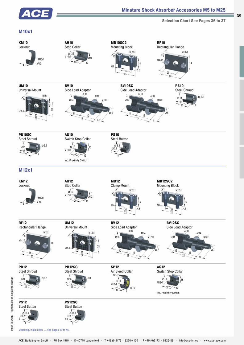
M10x1
KM10 Locknut
M10x1
4 AF12
AH10 Stop Collar
M10x112.5
20 10
10Ø
Ø
MB10SC2 Mounting Block
25
14
3.5
M10x1
M4
16
10
RF10 Rectangular Flange
28
14
6M10x1
20
M4x10
UM10 Universal Mount
38
25
5
M10x1
4.5
25
Ø
12
Minature Shock Absorber Accessories M5 to M25
Selection Chart See Pages 36 to 37
BV10 Side Load Adaptor
15
1112
AF11AF12
6.5
13 M10x1
6Ø
Ø
BV10SC Side Load Adaptor
15
1112
AF11AF12
8
13 M10x1
6Ø
Ø
PB10 Steel Shroud
14 3.2
314
22
Ø Ø
PB10SC Steel Shroud
14 3.2
415
22
Ø Ø
AS10 Switch Stop Collar
M10x117
22 12
15Ø
inc. Proximity Switch
PS10 Steel Button
8.8
58
3.2Ø
Ø
M12x1
KM12 Locknut
M12x1
5 AF14
AH12 Stop Collar
M12x115
20 10
12Ø
Ø
MB12 Clamp Mount
32
16
4.5
M12x1
M5
20
12
MB12SC2 Mounting Block
32
16
4.5
M12x1
M5
20
12
RF12 Rectangular Flange
32
20
6M12x1
24
M5x12
UM12 Universal Mount
38
25
5
M12x1
4.5
25Ø
12
BV12 Side Load Adaptor
22
1218
AF13AF14
12
15 M12x1
7Ø
Ø
BV12SC Side Load Adaptor
22
1218
AF13AF14
10
15 M12x1
7Ø
Ø
PB12 Steel Shroud
16 3.2
315
23
Ø Ø
PB12SC Steel Shroud
16 4
316
23
Ø Ø
SP12 Air Bleed Collar
18
310
M12x1AF16
3
Ø
Ø
AS12 Switch Stop Collar
M12x119
22 12
16Ø
inc. Proximity Switch
PS12 Steel Button
10.8
58
3.2Ø
Ø
PS12SC Steel Button
10.8
3.87
4Ø
Ø
Mounting, installation, ... see pages 43 to 46.
39Is
sue
08.2
016
– Sp
ecifi
catio
ns s
ubje
ct to
cha
nge
ACE Stoßdämpfer GmbH . PO Box 1510 . D-40740 Langenfeld . T +49 (0)2173 - 9226-4100 . F +49 (0)2173 - 9226-89 . [email protected] . www.ace-ace.com

Minature Shock Absorber Accessories M5 to M25
Selection Chart See Pages 36 to 37
KM14-V4A Locknut
M14x1.5
6 AF17
AH14 Stop Collar
M14x1.517
20 12
14Ø
Ø
AF15
AH14-V4A Stop Collar
M14x1.517
20 12
14Ø
Ø
AF15
MB14 Clamp Mount
32
20
4.5
M14x1.5
M520
12
MB14SC2 Mounting Block
32
20
4.5
M14x1.5
M520
12
MB14SC2-V4A Mounting Block
32
20
4.5
M14x1.5
M520
12
RF14 Rectangular Flange
34
20
6M14x1.5
26
M5x12
UM14 Universal Mount
45
29
5
M14x1.5
4.5
35
Ø
16
BV14 Side Load Adaptor
M14x1.518
2412 9
20
AF16 AF17
12.5
Ø
Ø
BV14SC Side Load Adaptor
M14x1.518
3014 9
26
AF16 AF17
16
Ø
Ø
PB14 Steel Shroud
18 4.8
4.515
25
Ø Ø
PB14SC Steel Shroud
18 4
4.522
32
Ø Ø
SP14 Air Bleed Collar
18
5.510
M14x1.5AF12
3
Ø
Ø
AS14 Switch Stop Collar
M14x1.521
22 12
17Ø
inc. Proximity Switch
PS14 Steel Button
124.5
11
4.8Ø
Ø
BP14 Steel/Urethane Button
12.2
7.212.2
4ØØ
PP150 Nylon Button
12
4.79.4
4.8Ø
Ø
W3 max = 14 Nm
M14x1.5
KM14 Locknut
M14x1.5
6 AF17
Mounting, installation, ... see pages 43 to 46.
40
Issu
e 08
.201
6 –
Spec
ifica
tions
sub
ject
to c
hang
e
ACE Stoßdämpfer GmbH . PO Box 1510 . D-40740 Langenfeld . T +49 (0)2173 - 9226-4100 . F +49 (0)2173 - 9226-89 . [email protected] . www.ace-ace.com

M20x1.5
KM20 Locknut
M20x1.5
8 AF23
KM20-V4A Locknut
M20x1.5
8 AF23
AH20 Stop Collar
M20x1.524.8
25 1220.5Ø
Ø
AF22
AH20-V4A Stop Collar
M20x1.524,8
25 1220.5Ø
Ø
AF22
MB20 Clamp Mount
40
25
6
M20x1.5
M628
20
MB20SC2 Mounting Block
50
25
13
M20x1.5
M834
20
MB20SC2-V4A Mounting Block
50
25
13
M20x1.5
M834
20
RF20 Rectangular Flange
46
32
8M20x1.5
36
M6x14
UM20 Universal Mount
47
35
10
M20x1.5
5.5
35
25.5
Ø
16
Minature Shock Absorber Accessories M5 to M25
Selection Chart See Pages 36 to 37
BV20 Side Load Adaptor
M20x1.524
24
14 1220
AF22 AF23
12.5
Ø
Ø
BV20SC Side Load Adaptor
M20x1.524
36
14 1232
AF22 AF23
19
Ø
Ø
PB20 Steel Shroud
24 6.3
415
24
Ø Ø
PB20SC Steel Shroud
24 4.8
526
37
Ø Ø
SP20 Air Bleed Collar
24
5.412
M20x1.5AF18
3
Ø
Ø
AS20 Switch Stop Collar
M20x1.526
25 12
20Ø
inc. Proximity Switch
PS20 Steel Button
16.8
4.411
6.3Ø
Ø
BP20 Steel/Urethane Button
16.8
6.913.1
4.8Ø
Ø
PP225 Nylon Button
17
3.98.8
6.3Ø
Ø
W3 max = 33 Nm
Mounting, installation, ... see pages 43 to 46.
41Is
sue
08.2
016
– Sp
ecifi
catio
ns s
ubje
ct to
cha
nge
ACE Stoßdämpfer GmbH . PO Box 1510 . D-40740 Langenfeld . T +49 (0)2173 - 9226-4100 . F +49 (0)2173 - 9226-89 . [email protected] . www.ace-ace.com
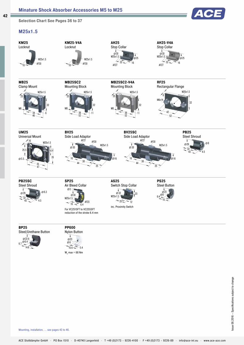
Minature Shock Absorber Accessories M5 to M25
Selection Chart See Pages 36 to 37
PB25SC Steel Shroud
29 6.3
4.532
43
Ø Ø
SP25 Air Bleed Collar
30
6.416
M25x1.5AF23
3
Ø
Ø
For VC2515FT to VC2555FT reduction of the stroke 6.4 mm
AS25 Switch Stop Collar
M25x1.532
25 12
23Ø
inc. Proximity Switch
PS25 Steel Button
23
6.410
8Ø
Ø
BP25 Steel/Urethane Button
22.6
6.714.6
6.4ØØ
PP600 Nylon Button
23
5.410.6
8ØØ
W3 max = 68 Nm
M25x1.5
KM25 Locknut
M25x1.5
10 AF30
KM25-V4A Locknut
M25x1.5
10 AF30
AH25 Stop Collar
M25x1.530
32 16
25Ø
Ø
AF27
AH25-V4A Stop Collar
M25x1.530
32 16
25Ø
Ø
AF27
MB25 Clamp Mount
46
32
6
M25x1.5
M634
25
MB25SC2 Mounting Block
52
32
11
M25x1.5
M836
25
MB25SC2-V4A Mounting Block
52
32
11
M25x1.5
M836
25
RF25 Rectangular Flange
52
32
8M25x1.5
42
M6x14
UM25 Universal Mount
47
35
10
M25x1.5
5.5
35
25.5
Ø
16
BV25 Side Load Adaptor
M25x1.530
44
16 1638
AF27 AF30
25
Ø
Ø
BV25SC Side Load Adaptor
M25x1.530
44
16 1638
AF27 AF30
25
Ø
Ø
PB25 Steel Shroud
29 8
4.532
43
Ø Ø
Mounting, installation, ... see pages 43 to 46.
42
Issu
e 08
.201
6 –
Spec
ifica
tions
sub
ject
to c
hang
e
ACE Stoßdämpfer GmbH . PO Box 1510 . D-40740 Langenfeld . T +49 (0)2173 - 9226-4100 . F +49 (0)2173 - 9226-89 . [email protected] . www.ace-ace.com
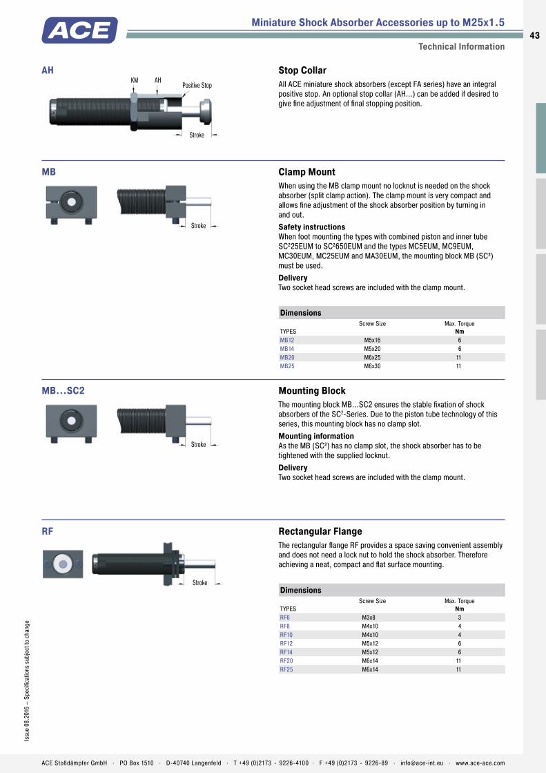
Miniature Shock Absorber Accessories up to M25x1.5
Technical Information
KM
Stroke
AHPositive Stop
AH Stop CollarAll ACE miniature shock absorbers (except FA series) have an integral positive stop. An optional stop collar (AH...) can be added if desired to give fine adjustment of final stopping position.
Stroke
MB Clamp MountWhen using the MB clamp mount no locknut is needed on the shock absorber (split clamp action). The clamp mount is very compact and allows fine adjustment of the shock absorber position by turning in and out.Safety instructions When foot mounting the types with combined piston and inner tube SC²25EUM to SC²650EUM and the types MC5EUM, MC9EUM, MC30EUM, MC25EUM and MA30EUM, the mounting block MB (SC²) must be used.Delivery Two socket head screws are included with the clamp mount.
Stroke
MB...SC2 Mounting BlockThe mounting block MB...SC2 ensures the stable fixation of shock absorbers of the SC2-Series. Due to the piston tube technology of this series, this mounting block has no clamp slot.Mounting information As the MB (SC²) has no clamp slot, the shock absorber has to be tightened with the supplied locknut.Delivery Two socket head screws are included with the clamp mount.
Stroke
RF Rectangular FlangeThe rectangular flange RF provides a space saving convenient assembly and does not need a lock nut to hold the shock absorber. Therefore achieving a neat, compact and flat surface mounting.
Dimensions
TYPESScrew Size Max. Torque
NmMB12 M5x16 6MB14 M5x20 6MB20 M6x25 11MB25 M6x30 11
Dimensions
TYPESScrew Size Max. Torque
NmRF6 M3x8 3RF8 M4x10 4RF10 M4x10 4RF12 M5x12 6RF14 M5x12 6RF20 M6x14 11RF25 M6x14 11
43Is
sue
08.2
016
– Sp
ecifi
catio
ns s
ubje
ct to
cha
nge
ACE Stoßdämpfer GmbH . PO Box 1510 . D-40740 Langenfeld . T +49 (0)2173 - 9226-4100 . F +49 (0)2173 - 9226-89 . [email protected] . www.ace-ace.com

Miniature Shock Absorber Accessories up to M25x1.5
Technical Information
Shock Absorber
Wiper Ring3Ø
SP
SP Air Bleed CollarAir bleed collar (includes integral stop collar) protects shock absorber from ingress of abrasive contaminents like cement, paper or wood dust into the rod seal area. It also prevents aggressive fluids such as cutting oils, coolants etc. damaging the seals. Air bleed supply 0.5 to 1 bar. Low air consumption. The constant air bleed prevents contaminants passing the wiper ring and entering the shock absorber seal area.Safety instructions Do not switch off air supply whilst machine is operating! The air bleed collar cannot be used on all similar body thread sized shock absorbers. The air bleed collar is only for types MC150EUM to MC600EUM, MA150EUM, SC75EUM and SC190EUM5-7.
Shock Absorber PP
PP Nylon ButtonWhile the use of industrial shock absorbers already achieves a considerable reduction in noise levels, the additional use of PP impact buttons made of glass fibre reinforced nylon reduces noise levels even further, making it easy to fulfil the regulations of the new Noise Control Ordinance. At the same time, wear of impact surface is drastically minimized. The PP buttons are available for shock absorbers in series MC150EUM to MC600EUM.Mounting information The buttons are fitted simply by pressing onto the piston rod.Delivery Model MA150EUM is supplied as standard with PP button.
Shock Absorber BP
BP Steel/Urethane ButtonThese impact buttons made of urethane offer all above advantages of the PP nylon button in terms of reducing noise and wear. They fit easily onto the piston rod of the corresponding shock absorber.Please refer to the accessories table on pages 36 to 37 to see which shock absorber types the BP buttons are available for.
PB
Stroke
Stroke
Shock Absorber
PB Steel ShroudGrinding beads, sand, welding splatter, paints and adhesives etc. can adhere to the piston rod. They then damage the rod seals and the shock absorber quickly fails. In many cases the installation of the optional steel shroud can provide worthwhile protection and increase lifetime.Ordering information The PB steel shroud can only be installed onto a shock absorber without rod end button.For part number MA, MC, SC please order with “M-880” suffix. Part numbers MA150EUM, MC150EUM to MC600EUM and SC25EUM to SC190EUM5-7 are supplied without a button.Safety instructions When installing don‘t forget to allow operating space for the shroud to move as the shock absorber is cycled.
44
Issu
e 08
.201
6 –
Spec
ifica
tions
sub
ject
to c
hang
e
ACE Stoßdämpfer GmbH . PO Box 1510 . D-40740 Langenfeld . T +49 (0)2173 - 9226-4100 . F +49 (0)2173 - 9226-89 . [email protected] . www.ace-ace.com

Shock Absorber Threaded Body Positive Stop Plunger
BV Side Load AdaptorRotating impact motion causes high side load forces on the piston rod. This increases bearing wear and possibly results in rod breakage or bending. With side load impact angles of more than 3° the operation lifetime of the shock absorber reduces rapidly due to increased wear of the rod bearings. The optional BV side load adaptor provides long lasting solution.Ordering information The BV adaptor can only be installed onto a shock absorber without rod end button.Part Number: MA, MC, SC...-880 (Models MC150EUM to MC600EUM and SC²25EUM to SC²190EUM5-7 are supplied as standard without buttons.)Material Threaded body and plunger: Hardened high tensile steel, hardened 610 HV1Mounting information Secure the side load adaptor with Loctite or locknut on the shock absorber.For material combination plunger/impact plate use similar hardness values. We recommend that you install the shock absorber/side load adaptor using the thread on the side load adaptor.Installation with clamp mount MB... not possible. Use mounting block MB... SC²!Safety instructions Maximum angle: BV8, BV10 and BV12 = 12.5° BV14, BV20 and BV25 = 25° By repositioning the centre of the stroke of the side load plunger to be at 90 degrees to the piston rod, the side load angle can be halved. The use of an external positive stop due to high forces encountered is required.
Rs
Stroke s
α
Formulae:
α = tan-1 Rs min =
Example:
s = 0.025 m α max = 25° (Type BV25)
Rs = 0.1 m
α = tan-1 Rs min =
α = 14.04° Rs min = 0.054 m
α = side load angle ° Rs = mounting radius mα max = max. angle ° Rs min = min. possibles = absorber stroke m mounting radius m
stan α max
0.025tan 25
sRs
( )
( )0.0250.1
Miniature Shock Absorber Accessories up to M25x1.5
Technical Information45
Issu
e 08
.201
6 –
Spec
ifica
tions
sub
ject
to c
hang
e
ACE Stoßdämpfer GmbH . PO Box 1510 . D-40740 Langenfeld . T +49 (0)2173 - 9226-4100 . F +49 (0)2173 - 9226-89 . [email protected] . www.ace-ace.com

Miniature Shock Absorber Accessories up to M25x1.5
Technical Information
PS
Stroke
ASmax 1 mm
AS Switch Stop CollarThe ACE stop light switch stop collar combination AS, incl. proximity switch PNP, can be mounted on all popular shock absorber models. The use of the steel button PS is mandatory. Advantages: Very short, compact mounting package, good price-perfor-mance ratio, retrofit possible for standard shock absorber models, fine adjustment of the stroke possible.Ordering information The steel button type PS is fitted as standard on the models: SC190EUM0-4, SC300EUM0-9, SC650EUM0-9, SC925EUM0-4, MA/MVC225EUM, MA/MVC600EUM and MA/MVC900EUM. With all other models you must order the PS button as an optional accessory.Mounting information We recommend to fix the steel button onto the end of the piston rod using Loctite 290. Attention! Take care not to leave any adhesive on the piston rod as this will cause seal damage. Thread the switch stop collar onto the front of the shock absorber and secure in position. Switch cable should not be routed close to power cables.
8 thick
20
7.5
105.5
2.5
3
app. 1000Length
M2.5Ø
250-3 PNP Proximity SwitchThe proximity switch is part of the ACE stop light switch collar combi-nation. The correct starting position can thus be checked electronically.Ordering information Part number: 250-3 PNPPNP proximity switch data Supply voltage: 10-27 VDC Ripple: <10 % Load current max.: 100 mA Operating temperature range: -10 °C to +60 °C Residual voltage: max. 1 V Protection: IP67 (IEC 144) with LED-indicator Proximity switch N/Open when shock absorber extended. When shock absorber is fully compressed switch closes and LED indicator lights.
+V
0V
max.100 mA
250-3PNPCircuit diagram PNP-switch
brown
blue
RedLED
Prox.maincircuit
Loadblack
46
Issu
e 08
.201
6 –
Spec
ifica
tions
sub
ject
to c
hang
e
ACE Stoßdämpfer GmbH . PO Box 1510 . D-40740 Langenfeld . T +49 (0)2173 - 9226-4100 . F +49 (0)2173 - 9226-89 . [email protected] . www.ace-ace.com

Application Examples
Miniature Shock Absorbers
MC25EUM
Constant deceleration forceACE miniature shock absorbers are the right alternative. This pneumatic module for high precision, high speed motion intentionally abandoned pneumatic end-of-travel damping. The compact miniature shock absorb-ers of the type MC25EUMH-NB decelerate the linear motion safer and faster when reaching the end-of-travel position. They accept the moving load gently and decelerate it smoothly throughout the entire stroke length. Additional advantages: simpler construction, smaller pneumatic valves, lower maintenance costs as well as reduced compressed air consumption.
s
mF
Miniature Shock Absorber in compact pneumatic module
SC190EUM
Soft end-of-travel damping on rotary movementsACE miniature shock absorbers optimize production with minimum expenditure. The cycle rate for an assembly line producing electronic components was increased to 3,600 units/hr. Miniature shock absorbers type SC190EUM-1 decelerate the rapid transfer movements on the production line and using soft damping methods optimize the pick up and set down of components. This soft deceleration technique has increased production and reduced maintenance on the portal and rotary actuator modules. The optional side load adaptor protects the shock absorber from high side load forces and increases the operating lifetime. Using ACE shock absorbers reduces maintenance costs by 50 % and running costs by 20 %, diminishing energy consumption.
Stroke sα
RS
Optimised production in the electronics industry
47Is
sue
08.2
016
– Sp
ecifi
catio
ns s
ubje
ct to
cha
nge
ACE Stoßdämpfer GmbH . PO Box 1510 . D-40740 Langenfeld . T +49 (0)2173 - 9226-4100 . F +49 (0)2173 - 9226-89 . [email protected] . www.ace-ace.com

Automation Control
ACE industrial shock absorbers work hard. Their application means moving loads are evenly decelerated over the full stroke. The result: the lowest braking force and shortest braking time. The MAGNUM series from ACE is viewed as the reference standard for medium design sizes in damping technology.
Innovations such as diaphragm accumulators, seals, tube-shaped inner pressure chambers and many more make a decisive contribution towards extension of the service life. This means that the effective load range can be extended considera-bly, which provides users with more scope with respect to the absorber size and utilisation of the machine‘s output. ACE offers a wide range of matching accesso-ries for this and all other absorber series. This eliminates internal production of assembly parts, which involves high costs and lots of time.
Industrial Shock AbsorbersAbsorbers to suit – for all loads
Reference class for medium sizes
Innovative damping techniques
Less stress on the machine
Long machine service lives
Increase of production fi gures
4848
ACE Stoßdämpfer GmbH . PO Box 1510 . D-40740 Langenfeld . T +49 (0)2173 - 9226-4100 . [email protected] . www.ace-ace.com
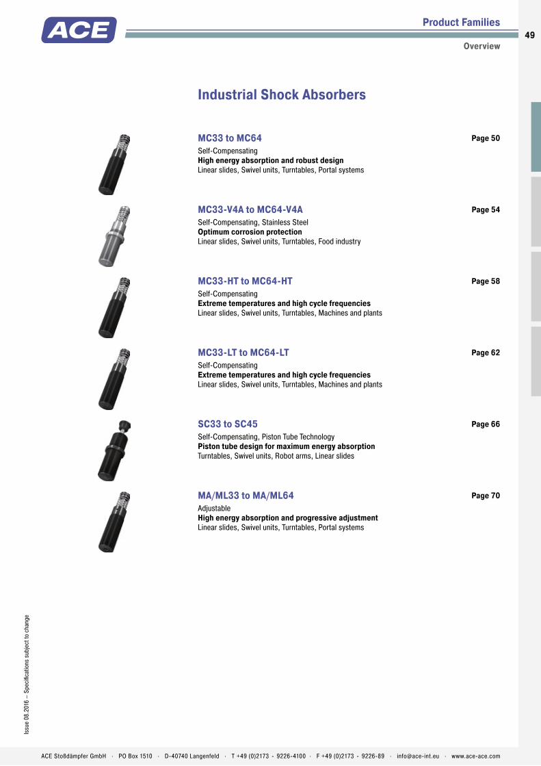
Product Families
Overview
Industrial Shock Absorbers
MC33 to MC64 Self-Compensating High energy absorption and robust designLinear slides, Swivel units, Turntables, Portal systems
Page 50
MC33-V4A to MC64-V4A Self-Compensating, Stainless Steel Optimum corrosion protectionLinear slides, Swivel units, Turntables, Food industry
Page 54
MC33-HT to MC64-HT Self-Compensating Extreme temperatures and high cycle frequenciesLinear slides, Swivel units, Turntables, Machines and plants
Page 58
MC33-LT to MC64-LT Self-Compensating Extreme temperatures and high cycle frequenciesLinear slides, Swivel units, Turntables, Machines and plants
Page 62
SC33 to SC45 Self-Compensating, Piston Tube Technology Piston tube design for maximum energy absorptionTurntables, Swivel units, Robot arms, Linear slides
Page 66
MA/ML33 to MA/ML64 Adjustable High energy absorption and progressive adjustmentLinear slides, Swivel units, Turntables, Portal systems
Page 70
Reference class for medium sizes
Innovative damping techniques
Less stress on the machine
Long machine service lives
Increase of production fi gures
49Is
sue
08.2
016
– Sp
ecifi
catio
ns s
ubje
ct to
cha
nge
ACE Stoßdämpfer GmbH . PO Box 1510 . D-40740 Langenfeld . T +49 (0)2173 - 9226-4100 . F +49 (0)2173 - 9226-89 . [email protected] . www.ace-ace.com

Piston Rod
Membrane Accumulator
Return Spring
One-Piece Outer Body without Retaining Ring
Piston Ring
Pressure Chamber with Metering Orifices
Rod Button
Seals
Piston
Positive Stop
Main Bearing
Outer Body
Technical Data
The latest damper technology: The combina-tion of the latest sealing technology, annealed guide bearing and integrated positiv stop make these self-compensating shock absorbers from ACE‘S MAGNUM range so successful. After all, users benefi t from the longer service life of the products, even in the most diffi cult environ-ments. A continuous outer thread and extensive accessories make their contribution to the success story of the MC33 to MC64.
High energy absorption in a compact design and a wide damping range lead to huge advantages in practice. Alongside generally more compact designs, these small yet very powerful absorbers enable full use of the machine‘s performance.
These self-compensating industrial shock absorbers are used in all areas of mechanical engineering – especially in automation and for gantries.
MC33 to MC64Industrial Shock Absorbers High energy absorption and robust design
Industrial Shock Absorbers
Self-Compensating
Energy capacity: 155 Nm/Cycle to 5,100 Nm/CycleImpact velocity range: 0.15 m/s to 5 m/s. Other speeds on request.Operating temperature range: -12 °C to +66 °C. Other temperatures on request.Mounting: In any positionPositive stop: IntegratedMaterial: Outer body: Nitride hardened steel; Piston rod: Hard chrome plated steel; Rod end button: Hardened steel and corrosion-resistant coating; Return spring: Zinc plated or
plastic-coated steel; Accessories: Steel with black oxide fi nish or nitride hardenedDamping medium: Automatic Transmission Fluid (ATF)Application fi eld: Linear slides, Swivel units, Turntables, Portal systemsNote: A noise reduction of 3 to 7 dB is possible when using the special impact button (PP). For emergency use only applications and for continous use (with additional cooling) it is sometimes possible to exceed the published max. capacity ratings. In this case, please consult ACE.
Safety instructions: External materials in the surrounding area can attack the seal components and lead to a shorter service life. Please contact ACE for appropriate solution suggestions. Do not paint the shock absorbers due to heat emission.On request: Special oils, nickel-plated, increased corrosion protection, mounting inside air cylinders or other special options are available on request.
50
Issu
e 08
.201
6 –
Spec
ifi ca
tions
sub
ject
to c
hang
e
ACE Stoßdämpfer GmbH . PO Box 1510 . D-40740 Langenfeld . T +49 (0)2173 - 9226-4100 . F +49 (0)2173 - 9226-89 . [email protected] . www.ace-ace.com
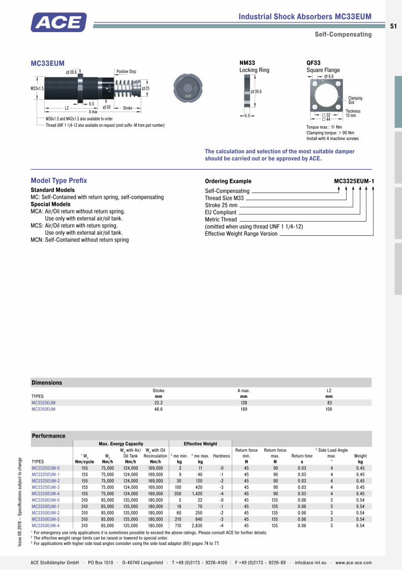
Piston Rod
Membrane Accumulator
Return Spring
One-Piece Outer Body without Retaining Ring
Piston Ring
Pressure Chamber with Metering Orifices
Rod Button
Seals
Piston
Positive Stop
Main Bearing
Outer Body
Industrial Shock Absorbers MC33EUM
Self-Compensating
The calculation and selection of the most suitable damper should be carried out or be approved by ACE.
Ordering Example MC3325EUM-1Self-CompensatingThread Size M33Stroke 25 mmEU CompliantMetric Thread(omitted when using thread UNF 1 1/4-12)Effective Weight Range Version
Model Type Prefi xStandard ModelsMC: Self-Contained with return spring, self-compensatingSpecial ModelsMCA: Air/Oil return without return spring.
Use only with external air/oil tank.MCS: Air/Oil return with return spring.
Use only with external air/oil tank.MCN: Self-Contained without return spring
PerformanceMax. Energy Capacity Effective Weight
TYPES
1 W3Nm/cycle
W4Nm/h
W4 with Air/Oil TankNm/h
W4 with Oil Recirculation
Nm/h2 me min.
kg2 me max.
kgHardness
Return force min.
N
Return force max.
NReturn time
s
3 Side Load Angle max.
°Weight
kgMC3325EUM-0 155 75,000 124,000 169,000 3 11 -0 45 90 0.03 4 0.45MC3325EUM-1 155 75,000 124,000 169,000 9 40 -1 45 90 0.03 4 0.45MC3325EUM-2 155 75,000 124,000 169,000 30 120 -2 45 90 0.03 4 0.45MC3325EUM-3 155 75,000 124,000 169,000 100 420 -3 45 90 0.03 4 0.45MC3325EUM-4 155 75,000 124,000 169,000 350 1,420 -4 45 90 0.03 4 0.45MC3350EUM-0 310 85,000 135,000 180,000 5 22 -0 45 135 0.06 3 0.54MC3350EUM-1 310 85,000 135,000 180,000 18 70 -1 45 135 0.06 3 0.54MC3350EUM-2 310 85,000 135,000 180,000 60 250 -2 45 135 0.06 3 0.54MC3350EUM-3 310 85,000 135,000 180,000 210 840 -3 45 135 0.06 3 0.54MC3350EUM-4 310 85,000 135,000 180,000 710 2,830 -4 45 135 0.06 3 0.54
1 For emergency use only applications it is sometimes possible to exceed the above ratings. Please consult ACE for further details.2 The effective weight range limits can be raised or lowered to special order.3 For applications with higher side load angles consider using the side load adaptor (BV) pages 74 to 77.
Dimensions
TYPESStroke
mmA max.
mmL2
mmMC3325EUM 23.2 138 83MC3350EUM 48.6 189 108
30
M33x1.5
L2 Stroke
25
A max
Positive Stop
M36x1.5 and M42x1.5 also available to orderThread UNF 1 1/4-12 also available on request (omit suffix -M from part number)
Ø
39.6Ø
Ø
6.5
MC33EUM QF33 Square Flange
44
Thickness10 mm
ClampingSlot
32
6.6Ø
Torque max.: 11 NmClamping torque: > 90 NmInstall with 4 machine screws
NM33 Locking Ring
6.5
39.6Ø
51Is
sue
08.2
016
– Sp
ecifi
catio
ns s
ubje
ct to
cha
nge
ACE Stoßdämpfer GmbH . PO Box 1510 . D-40740 Langenfeld . T +49 (0)2173 - 9226-4100 . F +49 (0)2173 - 9226-89 . [email protected] . www.ace-ace.com

Industrial Shock Absorbers MC45EUM
Self-Compensating
The calculation and selection of the most suitable damper should be carried out or be approved by ACE.
Ordering Example MC4550EUM-3Self-CompensatingThread Size M45Stroke 50 mmEU CompliantMetric Thread(omitted when using thread UNF 1 3/4-12)Effective Weight Range Version
Model Type PrefixStandard ModelsMC: Self-Contained with return spring, self-compensatingSpecial ModelsMCA: Air/Oil return without return spring.
Use only with external air/oil tank.MCS: Air/Oil return with return spring.
Use only with external air/oil tank.MCN: Self-Contained without return spring
PerformanceMax. Energy Capacity Effective Weight
TYPES
1 W3Nm/cycle
W4Nm/h
W4 with Air/Oil TankNm/h
W4 with Oil Recirculation
Nm/h2 me min.
kg2 me max.
kgHardness
Return force min.
N
Return force max.
NReturn time
s
3 Side Load Angle max.
°Weight
kgMC4525EUM-0 340 107,000 158,000 192,000 7 27 -0 70 100 0.03 4 1.13MC4525EUM-1 340 107,000 158,000 192,000 20 90 -1 70 100 0.03 4 1.13MC4525EUM-2 340 107,000 158,000 192,000 80 310 -2 70 100 0.03 4 1.13MC4525EUM-3 340 107,000 158,000 192,000 260 1,050 -3 70 100 0.03 4 1.13MC4525EUM-4 340 107,000 158,000 192,000 890 3,540 -4 70 100 0.03 4 1.13MC4550EUM-0 680 112,000 192,000 248,000 13 54 -0 70 145 0.08 3 1.36MC4550EUM-1 680 112,000 192,000 248,000 45 180 -1 70 145 0.08 3 1.36MC4550EUM-2 680 112,000 192,000 248,000 150 620 -2 70 145 0.08 3 1.36MC4550EUM-3 680 112,000 192,000 248,000 520 2,090 -3 70 145 0.08 3 1.36MC4550EUM-4 680 112,000 192,000 248,000 1,800 7,100 -4 70 145 0.08 3 1.36MC4575EUM-0 1,020 146,000 225,000 282,000 20 80 -0 50 180 0.11 2 1.59MC4575EUM-1 1,020 146,000 225,000 282,000 70 270 -1 50 180 0.11 2 1.59MC4575EUM-2 1,020 146,000 225,000 282,000 230 930 -2 50 180 0.11 2 1.59MC4575EUM-3 1,020 146,000 225,000 282,000 790 3,140 -3 50 180 0.11 2 1.59MC4575EUM-4 1,020 146,000 225,000 282,000 2,650 10,600 -4 50 180 0.11 2 1.59
1 For emergency use only applications it is sometimes possible to exceed the above ratings. Please consult ACE for further details.2 The effective weight range limits can be raised or lowered to special order.3 For applications with higher side load angles consider using the side load adaptor (BV) pages 74 to 77.
Dimensions
TYPESStroke
mmA max.
mmL2
mmMC4525EUM 23.1 145 95MC4550EUM 48.5 195 120MC4575EUM 73.9 246 145
42
M45x1.5
L2 Stroke
35
A max
Positive Stop
Thread UNF 1 3/4-12 also available on request (omit suffix -M from part number)
Ø
57.2Ø
Ø
9.5
MC45EUM QF45 Square Flange
56
Thickness12 mm
ClampingSlot
42
9Ø
Torque max.: 27 Nm Clamping torque: > 200 Nm Install with 4 machine screws
NM45 Locking Ring
9.5
55.6Ø
52
Issu
e 08
.201
6 –
Spec
ifica
tions
sub
ject
to c
hang
e
ACE Stoßdämpfer GmbH . PO Box 1510 . D-40740 Langenfeld . T +49 (0)2173 - 9226-4100 . F +49 (0)2173 - 9226-89 . [email protected] . www.ace-ace.com

Industrial Shock Absorbers MC64EUM
Self-Compensating
The calculation and selection of the most suitable damper should be carried out or be approved by ACE.
Ordering Example MC64100EUM-2Self-CompensatingThread Size M64Stroke 100 mmEU CompliantMetric Thread(omitted when using thread UNF 2 1/2-12)Effective Weight Range Version
Model Type PrefixStandard ModelsMC: Self-Contained with return spring, self-compensatingSpecial ModelsMCA: Air/Oil return without return spring.
Use only with external air/oil tank.MCS: Air/Oil return with return spring.
Use only with external air/oil tank.MCN: Self-Contained without return spring
PerformanceMax. Energy Capacity Effective Weight
TYPES
1 W3Nm/cycle
W4Nm/h
W4 with Air/Oil TankNm/h
W4 with Oil Recirculation
Nm/h2 me min.
kg2 me max.
kgHardness
Return force min.
N
Return force max.
NReturn time
s
3 Side Load Angle max.
°Weight
kgMC6450EUM-0 1,700 146,000 293,000 384,000 35 140 -0 90 155 0.12 4 2.9MC6450EUM-1 1,700 146,000 293,000 384,000 140 540 -1 90 155 0.12 4 2.9MC6450EUM-2 1,700 146,000 293,000 384,000 460 1,850 -2 90 155 0.12 4 2.9MC6450EUM-3 1,700 146,000 293,000 384,000 1,600 6,300 -3 90 155 0.12 4 2.9MC6450EUM-4 1,700 146,000 293,000 384,000 5,300 21,200 -4 90 155 0.12 4 2.9MC64100EUM-0 3,400 192,000 384,000 497,000 70 280 -0 105 270 0.34 3 3.7MC64100EUM-1 3,400 192,000 384,000 497,000 270 1,100 -1 105 270 0.34 3 3.7MC64100EUM-2 3,400 192,000 384,000 497,000 930 3,700 -2 105 270 0.34 3 3.7MC64100EUM-3 3,400 192,000 384,000 497,000 3,150 12,600 -3 105 270 0.34 3 3.7MC64100EUM-4 3,400 192,000 384,000 497,000 10,600 42,500 -4 105 270 0.34 3 3.7MC64150EUM-0 5,100 248,000 497,000 644,000 100 460 -0 75 365 0.48 2 5.1MC64150EUM-1 5,100 248,000 497,000 644,000 410 1,640 -1 75 365 0.48 2 5.1MC64150EUM-2 5,100 248,000 497,000 644,000 1,390 5,600 -2 75 365 0.48 2 5.1MC64150EUM-3 5,100 248,000 497,000 644,000 4,700 18,800 -3 75 365 0.48 2 5.1MC64150EUM-4 5,100 248,000 497,000 644,000 16,000 63,700 -4 75 365 0.48 2 5.1
1 For emergency use only applications it is sometimes possible to exceed the above ratings. Please consult ACE for further details.2 The effective weight range limits can be raised or lowered to special order.3 For applications with higher side load angles consider using the side load adaptor (BV) pages 74 to 77.
Dimensions
TYPESStroke
mmA max.
mmL2
mmMC6450EUM 48.6 225 140MC64100EUM 99.4 326 191MC64150EUM 150 450 241
60
M64x2
L2 Stroke
48
A max
Positive Stop
Thread UNF 2 1/2-12 also available onrequest (omit suffix -M from part number)
Ø
76.2Ø
Ø
9.5
Note: 150 mm stroke model does not include stop collar and positive stop is provided by the rod button (Ø 60 mm)
MC64EUM QF64 Quadratflansch
80
Breite16 mm
Klemm-schlitz
58
11Ø
Torque max.: 50 Nm Clamping torque: > 210 Nm Install with 4 machine screws
NM64 Locking Ring
9.5
76Ø
53Is
sue
08.2
016
– Sp
ecifi
catio
ns s
ubje
ct to
cha
nge
ACE Stoßdämpfer GmbH . PO Box 1510 . D-40740 Langenfeld . T +49 (0)2173 - 9226-4100 . F +49 (0)2173 - 9226-89 . [email protected] . www.ace-ace.com

Piston Rod
Membrane Accumulator
Return Spring
One-Piece Outer Body without Retaining Ring
Piston Ring
Pressure Chamber with Metering Orifices
Rod Button
Seals
Piston
Positive Stop
Main Bearing
Stainless Steel Outer Body
Stainless Steel Locking Ring
Technical Data
The latest damper technology in stainless steel: The self-compensating industrial shock absorbers MC33 to MC64 from the tried-and-tested and popular MAGNUM series is also available with all outer components made from stainless steel (material 1.4404). They are fi lled in the factory with special oil, which meets the permit conditions (NSF-H1) for the food industry.
Just like the standard product family, the MAGNUM stainless steel models are distin-guished by their robust, modern sealing technology, high energy absorption in a compact design, integrated positive stop and a wide damping range. Equipped with a PU head, they are available in thread sizes M33x1.5 to M64x2 with damping strokes up to 100 mm.
These self-compensating industrial shock absorbers made of stainless steel from ACE are mainly used in the food, medical, electro and offshore industries, but also in many other markets.
MC33-V4A to MC64-V4AIndustrial Shock Absorbers Optimum corrosion protection
Industrial Shock Absorbers
Self-Compensating, Stainless Steel
Energy capacity: 155 Nm/Cycle to 5,100 Nm/CycleImpact velocity range: 0.15 m/s to 5 m/s. Other speeds on request.Operating temperature range: -12 °C to +66 °C. Other temperatures on request.Mounting: In any positionPositive stop: IntegratedMaterial: Outer body, Main bearing, Accessories, Locking ring: Stainless steel (1.4404, AISI 316L); Piston rod: Hard chrome plated steel; Rod end button: Stainless steel
(1.4404, AISI 316L) with elastomer insert; Return spring: Stainless steelDamping medium: Special oil NSF-H1 approvedApplication fi eld: Linear slides, Swivel units, Turntables, Food industryNote: Impact button (PP) for noise reduction included. For emergency use only applications and for continous use (with additional cooling) it is sometimes possible to exceed the published max. capacity ratings. In this case, please consult ACE.
Safety instructions: External materials in the surrounding area can attack the seal components and lead to a shorter service life. Please contact ACE for appropriate solution suggestions. Do not paint the shock absorbers due to heat emission.On request: Special oils, other special options and special accessories are available on request.
54
Issu
e 08
.201
6 –
Spec
ifi ca
tions
sub
ject
to c
hang
e
ACE Stoßdämpfer GmbH . PO Box 1510 . D-40740 Langenfeld . T +49 (0)2173 - 9226-4100 . F +49 (0)2173 - 9226-89 . [email protected] . www.ace-ace.com

Piston Rod
Membrane Accumulator
Return Spring
One-Piece Outer Body without Retaining Ring
Piston Ring
Pressure Chamber with Metering Orifices
Rod Button
Seals
Piston
Positive Stop
Main Bearing
Stainless Steel Outer Body
Stainless Steel Locking Ring
Industrial Shock Absorbers MC33EUM-V4A
Self-Compensating, Stainless Steel
13.2Ø 30
29.2
StrokeL 2
A max
M33x1.5MC33EUM-V4A
The calculation and selection of the most suitable damper should be carried out or be approved by ACE.
Ordering Example MC3325EUM-2-V4ASelf-CompensatingThread Size M33Stroke 25 mmEU CompliantMetric ThreadEffective Weight Range VersionStainless Steel 1.4404/AISI 316L
Model Type Prefi xStandard ModelsMC: Self-Contained with return spring, self-compensatingSpecial ModelsMCA: Air/Oil return without return spring.
Use only with external air/oil tank.MCS: Air/Oil return with return spring.
Use only with external air/oil tank.MCN: Self-Contained without return spring
Performance and DimensionsMax. Energy Capacity Effective Weight
TYPESW3
Nm/cycleW4
Nm/h1 me min.
kg1 me max.
kgHardness Stroke
mmA max.
mmL2
mm
Return force min.
N
Return force max.
NReturn time
s
2 Side Load Angle max.
°Weight
kgMC3325EUM-0-V4A 155 75,000 3 11 -0 23.2 151.2 83 45 90 0.03 4 0.45MC3325EUM-1-V4A 155 75,000 9 40 -1 23.2 151.2 83 45 90 0.03 4 0.45MC3325EUM-2-V4A 155 75,000 30 120 -2 23.2 151.2 83 45 90 0.03 4 0.45MC3325EUM-3-V4A 155 75,000 100 420 -3 23.2 151.2 83 45 90 0.03 4 0.45MC3325EUM-4-V4A 155 75,000 350 1,420 -4 23.2 151.2 83 45 90 0.03 4 0.45MC3350EUM-0-V4A 310 85,000 5 22 -0 48.6 202.2 108 45 135 0.06 3 0.54MC3350EUM-1-V4A 310 85,000 18 70 -1 48.6 202.2 108 45 135 0.06 3 0.54MC3350EUM-2-V4A 310 85,000 60 250 -2 48.6 202.2 108 45 135 0.06 3 0.54MC3350EUM-3-V4A 310 85,000 210 840 -3 48.6 202.2 108 45 135 0.06 3 0.54MC3350EUM-4-V4A 310 85,000 710 2,830 -4 48.6 202.2 108 45 135 0.06 3 0.54
1 For emergency use only applications it is sometimes possible to exceed the above ratings. Please consult ACE for further details.2 For applications with higher side load angles consider using the side load adaptor (BV) pages 74 to 77.
QF33-V4A Quadratfl ansch
44
Breite10 mm32
6,6Ø
NM33-V4A Locking Ring
6.5
39.6Ø
55Is
sue
08.2
016
– Sp
ecifi
catio
ns s
ubje
ct to
cha
nge
ACE Stoßdämpfer GmbH . PO Box 1510 . D-40740 Langenfeld . T +49 (0)2173 - 9226-4100 . F +49 (0)2173 - 9226-89 . [email protected] . www.ace-ace.com

Industrial Shock Absorbers MC45EUM-V4A
Self-Compensating, Stainless Steel
19.4Ø 42
42
StrokeL 2
A max
M45x1.5MC45EUM-V4A
The calculation and selection of the most suitable damper should be carried out or be approved by ACE.
Ordering Example MC4550EUM-1-V4ASelf-CompensatingThread Size M45Stroke 50 mmEU CompliantMetric ThreadEffective Weight Range VersionStainless Steel 1.4404/AISI 316L
Model Type PrefixStandard ModelsMC: Self-Contained with return spring, self-compensatingSpecial ModelsMCA: Air/Oil return without return spring.
Use only with external air/oil tank.MCS: Air/Oil return with return spring.
Use only with external air/oil tank.MCN: Self-Contained without return spring
Performance and DimensionsMax. Energy Capacity Effective Weight
TYPESW3
Nm/cycleW4
Nm/h1 me min.
kg1 me max.
kgHardness Stroke
mmA max.
mmL2
mm
Return force min.
N
Return force max.
NReturn time
s
2 Side Load Angle max.
°Weight
kgMC4525EUM-0-V4A 340 107,000 7 27 -0 23.1 164.5 95 70 100 0.03 4 1.13MC4525EUM-1-V4A 340 107,000 20 90 -1 23.1 164.5 95 70 100 0.03 4 1.13MC4525EUM-2-V4A 340 107,000 80 310 -2 23.1 164.5 95 70 100 0.03 4 1.13MC4525EUM-3-V4A 340 107,000 260 1,050 -3 23.1 164.5 95 70 100 0.03 4 1.13MC4525EUM-4-V4A 340 107,000 890 3,540 -4 23.1 164.5 95 70 100 0.03 4 1.13MC4550EUM-0-V4A 680 112,000 13 54 -0 48.5 214.4 120 70 145 0.08 3 1.36MC4550EUM-1-V4A 680 112,000 45 180 -1 48.5 214.4 120 70 145 0.08 3 1.36MC4550EUM-2-V4A 680 112,000 150 620 -2 48.5 214.4 120 70 145 0.08 3 1.36MC4550EUM-3-V4A 680 112,000 520 2,090 -3 48.5 214.4 120 70 145 0.08 3 1.36MC4550EUM-4-V4A 680 112,000 1,800 7,100 -4 48.5 214.4 120 70 145 0.08 3 1.36MC4575EUM-0-V4A 1,020 146,000 20 80 -0 73.9 265.4 145 50 180 0.11 2 1.59MC4575EUM-1-V4A 1,020 146,000 70 270 -1 73.9 265.4 145 50 180 0.11 2 1.59MC4575EUM-2-V4A 1,020 146,000 230 930 -2 73.9 265.4 145 50 180 0.11 2 1.59MC4575EUM-3-V4A 1,020 146,000 790 3,140 -3 73.9 265.4 145 50 180 0.11 2 1.59MC4575EUM-4-V4A 1,020 146,000 2,650 10,600 -4 73.9 265.4 145 50 180 0.11 2 1.59
1 For emergency use only applications it is sometimes possible to exceed the above ratings. Please consult ACE for further details.2 For applications with higher side load angles consider using the side load adaptor (BV) pages 74 to 77.
QF45-V4A Square Flange
56
Thickness12 mm42
9Ø
NM45-V4A Locking Ring
9.5
55.6Ø
56
Issu
e 08
.201
6 –
Spec
ifica
tions
sub
ject
to c
hang
e
ACE Stoßdämpfer GmbH . PO Box 1510 . D-40740 Langenfeld . T +49 (0)2173 - 9226-4100 . F +49 (0)2173 - 9226-89 . [email protected] . www.ace-ace.com
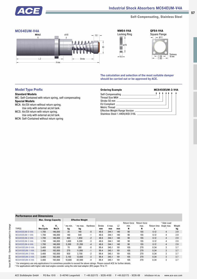
Industrial Shock Absorbers MC64EUM-V4A
Self-Compensating, Stainless Steel
19.1Ø 60
60
StrokeL 2A max
M64x2MC64EUM-V4A
The calculation and selection of the most suitable damper should be carried out or be approved by ACE.
Ordering Example MC6450EUM-3-V4ASelf-CompensatingThread Size M64Stroke 50 mmEU CompliantMetric ThreadEffective Weight Range VersionStainless Steel 1.4404/AISI 316L
Model Type PrefixStandard ModelsMC: Self-Contained with return spring, self-compensatingSpecial ModelsMCA: Air/Oil return without return spring.
Use only with external air/oil tank.MCS: Air/Oil return with return spring.
Use only with external air/oil tank.MCN: Self-Contained without return spring
Performance and DimensionsMax. Energy Capacity Effective Weight
TYPESW3
Nm/cycleW4
Nm/h1 me min.
kg1 me max.
kgHardness Stroke
mmA max.
mmL2
mm
Return force min.
N
Return force max.
NReturn time
s
2 Side Load Angle max.
°Weight
kgMC6450EUM-0-V4A 1,700 146,000 35 140 -0 48.6 244.1 140 90 155 0.12 4 2.9MC6450EUM-1-V4A 1,700 146,000 140 540 -1 48.6 244.1 140 90 155 0.12 4 2.9MC6450EUM-2-V4A 1,700 146,000 460 1,850 -2 48.6 244.1 140 90 155 0.12 4 2.9MC6450EUM-3-V4A 1,700 146,000 1,600 6,300 -3 48.6 244.1 140 90 155 0.12 4 2.9MC6450EUM-4-V4A 1,700 146,000 5,300 21,200 -4 48.6 244.1 140 90 155 0.12 4 2.9MC64100EUM-0-V4A 3,400 192,000 70 280 -0 99.4 345.1 191 105 270 0.34 3 3.7MC64100EUM-1-V4A 3,400 192,000 270 11,000 -1 99.4 345.1 191 105 270 0.34 3 3.7MC64100EUM-2-V4A 3,400 192,000 930 3,700 -2 99.4 345.1 191 105 270 0.34 3 3.7MC64100EUM-3-V4A 3,400 192,000 3,150 12,600 -3 99.4 345.1 191 105 270 0.34 3 3.7MC64100EUM-4-V4A 3,400 192,000 10,600 42,500 -4 99.4 345.1 191 105 270 0.34 3 3.7
1 For emergency use only applications it is sometimes possible to exceed the above ratings. Please consult ACE for further details.2 For applications with higher side load angles consider using the side load adaptor (BV) pages 74 to 77.
QF64-V4A Square Flange
80
Thickness16 mm58
11Ø
NM64-V4A Locking Ring
9.5
76Ø
57Is
sue
08.2
016
– Sp
ecifi
catio
ns s
ubje
ct to
cha
nge
ACE Stoßdämpfer GmbH . PO Box 1510 . D-40740 Langenfeld . T +49 (0)2173 - 9226-4100 . F +49 (0)2173 - 9226-89 . [email protected] . www.ace-ace.com
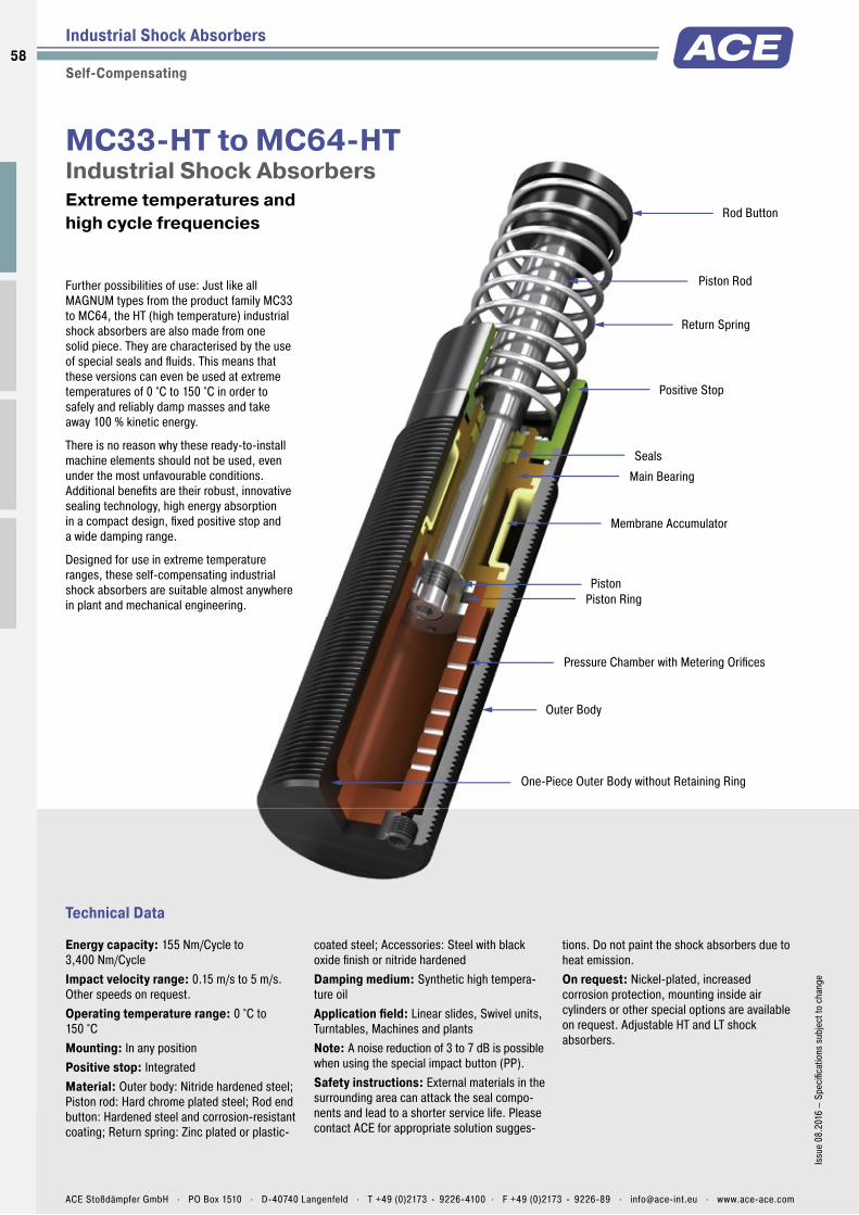
Piston Rod
Membrane Accumulator
Return Spring
One-Piece Outer Body without Retaining Ring
Piston Ring
Pressure Chamber with Metering Orifices
Rod Button
Seals
Piston
Positive Stop
Main Bearing
Outer Body
Technical Data
Further possibilities of use: Just like all MAGNUM types from the product family MC33 to MC64, the HT (high temperature) industrial shock absorbers are also made from one solid piece. They are characterised by the use of special seals and fl uids. This means that these versions can even be used at extreme temperatures of 0 °C to 150 °C in order to safely and reliably damp masses and take away 100 % kinetic energy.
There is no reason why these ready-to-install machine elements should not be used, even under the most unfavourable conditions. Additional benefi ts are their robust, innovative sealing technology, high energy absorption in a compact design, fi xed positive stop and a wide damping range.
Designed for use in extreme temperature ranges, these self-compensating industrial shock absorbers are suitable almost anywhere in plant and mechanical engineering.
MC33-HT to MC64-HTIndustrial Shock Absorbers Extreme temperatures and high cycle frequencies
Industrial Shock Absorbers
Self-Compensating
Energy capacity: 155 Nm/Cycle to 3,400 Nm/CycleImpact velocity range: 0.15 m/s to 5 m/s. Other speeds on request.Operating temperature range: 0 °C to 150 °CMounting: In any positionPositive stop: IntegratedMaterial: Outer body: Nitride hardened steel; Piston rod: Hard chrome plated steel; Rod end button: Hardened steel and corrosion-resistant coating; Return spring: Zinc plated or plastic-
coated steel; Accessories: Steel with black oxide fi nish or nitride hardenedDamping medium: Synthetic high tempera-ture oilApplication fi eld: Linear slides, Swivel units, Turntables, Machines and plantsNote: A noise reduction of 3 to 7 dB is possible when using the special impact button (PP).Safety instructions: External materials in the surrounding area can attack the seal compo-nents and lead to a shorter service life. Please contact ACE for appropriate solution sugges-
tions. Do not paint the shock absorbers due to heat emission.On request: Nickel-plated, increased corrosion protection, mounting inside air cylinders or other special options are available on request. Adjustable HT and LT shock absorbers.
58
Issu
e 08
.201
6 –
Spec
ifi ca
tions
sub
ject
to c
hang
e
ACE Stoßdämpfer GmbH . PO Box 1510 . D-40740 Langenfeld . T +49 (0)2173 - 9226-4100 . F +49 (0)2173 - 9226-89 . [email protected] . www.ace-ace.com

Piston Rod
Membrane Accumulator
Return Spring
One-Piece Outer Body without Retaining Ring
Piston Ring
Pressure Chamber with Metering Orifices
Rod Button
Seals
Piston
Positive Stop
Main Bearing
Outer Body
Industrial Shock Absorbers MC33EUM-HT
Self-Compensating
Ordering Example MC3350EUM-2-HTSelf-CompensatingThread Size M33Stroke 50 mmEU CompliantMetric Thread (omitted when using thread UNF)Effective Weight Range CodeHT = Version for High Temperature Use
Complete details required when ordering Load to be decelerated: m (kg)Impact velocity: v (m/s)Propelling force: F (N)Operating cycles per hour: c (/hr)Number of absorbers in parallel: nAmbient temperature: °C
PerformanceMax. Energy Capacity Effective Weight
TYPESW3
Nm/cycleW4 at 20 °C
Nm/hW4 at 100 °C
Nm/h1 me min.
kg1 me max.
kgHardness 2 Side Load Angle max.
°Weight
kgMC3325EUM-0-HT 155 215,000 82,000 3 11 -0 4 0.45MC3325EUM-1-HT 155 215,000 82,000 9 40 -1 4 0.45MC3325EUM-2-HT 155 215,000 82,000 30 120 -2 4 0.45MC3325EUM-3-HT 155 215,000 82,000 100 420 -3 4 0.45MC3325EUM-4-HT 155 215,000 82,000 350 1,420 -4 4 0.45MC3350EUM-0-HT 310 244,000 93,000 5 22 -0 3 0.54MC3350EUM-1-HT 310 244,000 93,000 18 70 -1 3 0.54MC3350EUM-2-HT 310 244,000 93,000 60 250 -2 3 0.54MC3350EUM-3-HT 310 244,000 93,000 240 840 -3 3 0.54MC3350EUM-4-HT 310 244,000 93,000 710 2,830 -4 3 0.54
1 The effective weight range limits can be raised or lowered to special order.2 For applications with higher side load angles consider using the side load adaptor (BV) pages 74 to 77.
Dimensions
TYPESStroke
mmA max.
mmd1
mmd2
mmL2
mmM
MC3325EUM-HT 23.2 138 30 25 83 M33x1.5MC3350EUM-HT 48.6 189 30 25 108 M33x1.5
d1
M
L2 Stroke
d2
A max
Positive Stop
Note: 150 mm stroke model does not include stop collar and positive stop is provided by the rod button (Ø 60 mm)
MC33EUM-HT QF33 Square Flange
44
Thickness10 mm
ClampingSlot
32
6.6Ø
Torque max.: 11 NmClamping torque: > 90 NmInstall with 4 machine screws
NM33 Locking Ring
6.5
39.6Ø
The calculation and selection of the most suitable damper should be carried out or be approved by ACE.
59Is
sue
08.2
016
– Sp
ecifi
catio
ns s
ubje
ct to
cha
nge
ACE Stoßdämpfer GmbH . PO Box 1510 . D-40740 Langenfeld . T +49 (0)2173 - 9226-4100 . F +49 (0)2173 - 9226-89 . [email protected] . www.ace-ace.com

Industrial Shock Absorbers MC45EUM-HT
Self-Compensating
Ordering Example MC4525EUM-3-HTSelf-CompensatingThread Size M45Stroke 25 mmEU CompliantMetric Thread (omitted when using thread UNF)Effective Weight Range CodeHT = Version for High Temperature Use
Complete details required when ordering Load to be decelerated: m (kg)Impact velocity: v (m/s)Propelling force: F (N)Operating cycles per hour: c (/hr)Number of absorbers in parallel: nAmbient temperature: °C
PerformanceMax. Energy Capacity Effective Weight
TYPESW3
Nm/cycleW4 at 20 °C
Nm/hW4 at 100 °C
Nm/h1 me min.
kg1 me max.
kgHardness 2 Side Load Angle max.
°Weight
kgMC4525EUM-0-HT 340 307,000 117,000 7 27 -0 4 1.13MC4525EUM-1-HT 340 307,000 117,000 20 90 -1 4 1.13MC4525EUM-2-HT 340 307,000 117,000 80 310 -2 4 1.13MC4525EUM-3-HT 340 307,000 117,000 260 1,050 -3 4 1.13MC4525EUM-4-HT 340 307,000 117,000 890 3,540 -4 4 1.13MC4550EUM-0-HT 680 321,000 122,000 13 54 -0 3 1.36MC4550EUM-1-HT 680 321,000 122,000 45 180 -1 3 1.36MC4550EUM-2-HT 680 321,000 122,000 150 620 -2 3 1.36MC4550EUM-3-HT 680 321,000 122,000 520 2,090 -3 3 1.36MC4550EUM-4-HT 680 321,000 122,000 1,800 7,100 -4 3 1.36
1 The effective weight range limits can be raised or lowered to special order.2 For applications with higher side load angles consider using the side load adaptor (BV) pages 74 to 77.
Dimensions
TYPESStroke
mmA max.
mmd1
mmd2
mmL2
mmM
MC4525EUM-HT 23.1 145 42 35 95 M45x1.5MC4550EUM-HT 48.5 195 42 35 120 M45x1.5
d1
M
L2 Stroke
d2
A max
Positive Stop
Note: 150 mm stroke model does not include stop collar and positive stop is provided by the rod button (Ø 60 mm)
MC45EUM-HT QF45 Square Flange
56
Thickness12 mm
ClampingSlot
42
9Ø
Torque max.: 27 Nm Clamping torque: > 200 Nm Install with 4 machine screws
NM45 Locking Ring
9.5
55.6Ø
The calculation and selection of the most suitable damper should be carried out or be approved by ACE.
60
Issu
e 08
.201
6 –
Spec
ifica
tions
sub
ject
to c
hang
e
ACE Stoßdämpfer GmbH . PO Box 1510 . D-40740 Langenfeld . T +49 (0)2173 - 9226-4100 . F +49 (0)2173 - 9226-89 . [email protected] . www.ace-ace.com

Industrial Shock Absorbers MC64EUM-HT
Self-Compensating
Ordering Example MC6450EUM-1-HTSelf-CompensatingThread Size M64Stroke 50 mmEU CompliantMetric Thread (omitted when using thread UNF)Effective Weight Range CodeHT = Version for High Temperature Use
Complete details required when ordering Load to be decelerated: m (kg)Impact velocity: v (m/s)Propelling force: F (N)Operating cycles per hour: c (/hr)Number of absorbers in parallel: nAmbient temperature: °C
PerformanceMax. Energy Capacity Effective Weight
TYPESW3
Nm/cycleW4 at 20 °C
Nm/hW4 at 100 °C
Nm/h1 me min.
kg1 me max.
kgHardness 2 Side Load Angle max.
°Weight
kgMC6450EUM-0-HT 1,700 419,000 159,000 35 140 -0 4 2.90MC6450EUM-1-HT 1,700 419,000 159,000 140 540 -1 4 2.90MC6450EUM-2-HT 1,700 419,000 159,000 460 1,850 -2 4 2.90MC6450EUM-3-HT 1,700 419,000 159,000 1,600 6,300 -3 4 2.90MC6450EUM-4-HT 1,700 419,000 159,000 5,300 21,200 -4 4 2.90MC64100EUM-0-HT 3,400 550,000 200,000 70 280 -0 3 3.70MC64100EUM-1-HT 3,400 550,000 200,000 270 1,100 -1 3 3.70MC64100EUM-2-HT 3,400 550,000 200,000 930 3,700 -2 3 3.70MC64100EUM-3-HT 3,400 550,000 200,000 3,150 12,600 -3 3 3.70MC64100EUM-4-HT 3,400 550,000 200,000 10,600 42,500 -4 3 3.70
1 The effective weight range limits can be raised or lowered to special order.2 For applications with higher side load angles consider using the side load adaptor (BV) pages 74 to 77.
Dimensions
TYPESStroke
mmA max.
mmd1
mmd2
mmL2
mmM
MC6450EUM-HT 48.6 225 60 48 140 M64x2MC64100EUM-HT 99.4 326 60 48 191 M64x2
d1
M
L2 Stroke
d2
A max
Positive Stop
Note: 150 mm stroke model does not include stop collar and positive stop is provided by the rod button (Ø 60 mm)
MC64EUM-HT QF64 Square Flange
80
Thickness16 mm
ClampingSlot
58
11Ø
Torque max.: 50 Nm Clamping torque: > 210 Nm Install with 4 machine screws
NM64 Locking Ring
9.5
76Ø
The calculation and selection of the most suitable damper should be carried out or be approved by ACE.
61Is
sue
08.2
016
– Sp
ecifi
catio
ns s
ubje
ct to
cha
nge
ACE Stoßdämpfer GmbH . PO Box 1510 . D-40740 Langenfeld . T +49 (0)2173 - 9226-4100 . F +49 (0)2173 - 9226-89 . [email protected] . www.ace-ace.com

Piston Rod
Membrane Accumulator
Return Spring
One-Piece Outer Body without Retaining Ring
Piston Ring
Pressure Chamber with Metering Orifices
Rod Button
Seals
Piston
Positive Stop
Main Bearing
Outer Body
Technical Data
Further possibilities of use: Just like all MAGNUM types from the product family MC33 to MC64, the LT (low temperature) industrial shock absorbers are also made from one solid piece. They are characterised by the use of special seals and fl uids. This means that these versions can even be used at extreme temperatures of -50 °C to +66 °C in order to safely and reliable damp masses and take away 100 % kinetic energy.
There is no reason why these ready-to-install machine elements should not be used, even under the most unfavourable conditions. Additional benefi ts are their robust, innovative sealing technology, high energy absorption in a compact design, fi xed positive stop and a wide damping range.
Designed for use in extreme temperature ranges, these self-compensating industrial shock absorbers are suitable almost anywhere in plant and mechanical engineering.
MC33-LT to MC64-LTIndustrial Shock Absorbers Extreme temperatures and high cycle frequencies
Industrial Shock Absorbers
Self-Compensating
Energy capacity: 155 Nm/Cycle to 5,100 Nm/CycleImpact velocity range: 0.15 m/s to 5 m/s. Other speeds on request.Operating temperature range: -50 °C to +66 °CMounting: In any positionPositive stop: IntegratedMaterial: Outer body: Nitride hardened steel; Piston rod: Hard chrome plated steel; Rod end button: Hardened steel and corrosion-resistant coating; Return spring: Zinc plated or plastic-
coated steel; Accessories: Steel with black oxide fi nish or nitride hardenedDamping medium: Low temperature hydraulic oilApplication fi eld: Linear slides, Swivel units, Turntables, Machines and plantsNote: A noise reduction of 3 to 7 dB is possible when using the special impact button (PP).Safety instructions: External materials in the surrounding area can attack the seal compo-nents and lead to a shorter service life. Please contact ACE for appropriate solution sugges-
tions. Do not paint the shock absorbers due to heat emission.On request: Nickel-plated, increased corrosion protection, mounting inside air cylinders or other special options are available on request. Adjustable HT and LT shock absorbers.
62
Issu
e 08
.201
6 –
Spec
ifi ca
tions
sub
ject
to c
hang
e
ACE Stoßdämpfer GmbH . PO Box 1510 . D-40740 Langenfeld . T +49 (0)2173 - 9226-4100 . F +49 (0)2173 - 9226-89 . [email protected] . www.ace-ace.com

Piston Rod
Membrane Accumulator
Return Spring
One-Piece Outer Body without Retaining Ring
Piston Ring
Pressure Chamber with Metering Orifices
Rod Button
Seals
Piston
Positive Stop
Main Bearing
Outer Body
Industrial Shock Absorbers MC33EUM-LT
Self-Compensating
Ordering Example MC3325EUM-2-LTSelf-CompensatingThread Size M33Stroke 25 mmEU CompliantMetric Thread (omitted when using thread UNF)Effective Weight Range CodeLT = Version for Low Temperature Use
Complete details required when ordering Load to be decelerated: m (kg)Impact velocity: v (m/s)Propelling force: F (N)Operating cycles per hour: c (/hr)Number of absorbers in parallel: nAmbient temperature: °C
PerformanceMax. Energy Capacity Effective Weight
TYPESW3
Nm/cycleW4
Nm/h1 me min.
kg1 me max.
kgHardness 2 Return time
s3 Side Load Angle max.
°Weight
kgMC3325EUM-0-LT 155 75,000 3 11 -0 0.08 4 0.45MC3325EUM-1-LT 155 75,000 9 40 -1 0.08 4 0.45MC3325EUM-2-LT 155 75,000 30 120 -2 0.08 4 0.45MC3325EUM-3-LT 155 75,000 100 420 -3 0.08 4 0.45MC3325EUM-4-LT 155 75,000 350 1,420 -4 0.08 4 0.45MC3350EUM-0-LT 310 85,000 5 22 -0 0.16 3 0.54MC3350EUM-1-LT 310 85,000 18 70 -1 0.16 3 0.54MC3350EUM-2-LT 310 85,000 60 250 -2 0.16 3 0.54MC3350EUM-3-LT 310 85,000 240 840 -3 0.16 3 0.54MC3350EUM-4-LT 310 85,000 710 2,830 -4 0,16 3 0.54
1 The effective weight range limits can be raised or lowered to special order.2 at -50 °C3 For applications with higher side load angles consider using the side load adaptor (BV) pages 74 to 77.
Dimensions
TYPESStroke
mmA max.
mmd1
mmd2
mmL2
mmM
MC3325EUM-LT 23.2 138 30 25 83 M33x1.5MC3350EUM-LT 48.6 189 30 25 108 M33x1.5
d1
M
L2 Stroke
d2
A max
Positive Stop
Note: 150 mm stroke model does not include stop collar and positive stop is provided by the rod button (Ø 60 mm)
MC33EUM-LT QF33 Square Flange
44
Thickness10 mm
ClampingSlot
32
6.6Ø
Torque max.: 11 NmClamping torque: > 90 NmInstall with 4 machine screws
NM33 Locking Ring
6.5
39.6Ø
The calculation and selection of the most suitable damper should be carried out or be approved by ACE.
63Is
sue
08.2
016
– Sp
ecifi
catio
ns s
ubje
ct to
cha
nge
ACE Stoßdämpfer GmbH . PO Box 1510 . D-40740 Langenfeld . T +49 (0)2173 - 9226-4100 . F +49 (0)2173 - 9226-89 . [email protected] . www.ace-ace.com

Industrial Shock Absorbers MC45EUM-LT
Self-Compensating
Ordering Example MC4525EUM-3-LTSelf-CompensatingThread Size M45Stroke 25 mmEU CompliantMetric Thread (omitted when using thread UNF)Effective Weight Range CodeLT = Version for Low Temperature Use
Complete details required when ordering Load to be decelerated: m (kg)Impact velocity: v (m/s)Propelling force: F (N)Operating cycles per hour: c (/hr)Number of absorbers in parallel: nAmbient temperature: °C
PerformanceMax. Energy Capacity Effective Weight
TYPESW3
Nm/cycleW4
Nm/h1 me min.
kg1 me max.
kgHardness 2 Return time
s3 Side Load Angle max.
°Weight
kgMC4525EUM-0-LT 340 107,000 7 27 -0 0.08 4 1.13MC4525EUM-1-LT 340 107,000 20 90 -1 0.08 4 1.13MC4525EUM-2-LT 340 107,000 80 310 -2 0.08 4 1.13MC4525EUM-3-LT 340 107,000 260 1,050 -3 0.08 4 1.13MC4525EUM-4-LT 340 107,000 890 3,540 -4 0.08 4 1.13MC4550EUM-0-LT 680 112,000 13 54 -0 0.16 3 1.36MC4550EUM-1-LT 680 112,000 45 180 -1 0.16 3 1.36MC4550EUM-2-LT 680 112,000 150 620 -2 0.16 3 1.36MC4550EUM-3-LT 680 112,000 520 2,090 -3 0.16 3 1.36MC4550EUM-4-LT 680 112,000 1,800 7,100 -4 0.16 3 1.36MC4575EUM-0-LT 1,020 146,000 20 80 -0 0.24 2 1.59MC4575EUM-1-LT 1,020 146,000 20 80 -1 0.24 2 1.59MC4575EUM-2-LT 1,020 146,000 70 270 -2 0.24 2 1.59MC4575EUM-3-LT 1,020 146,000 230 930 -3 0.24 2 1.59MC4575EUM-4-LT 1,020 146,000 2,650 10,600 -4 0.24 2 1.59
1 The effective weight range limits can be raised or lowered to special order.2 at -50 °C3 For applications with higher side load angles consider using the side load adaptor (BV) pages 74 to 77.
Dimensions
TYPESStroke
mmA max.
mmd1
mmd2
mmL2
mmM
MC4525EUM-LT 23.1 145 42 35 95 M45x1.5MC4550EUM-LT 48.5 195 42 35 120 M45x1.5MC4575EUM-LT 73.9 246 42 35 145 M45x1.5
d1
M
L2 Stroke
d2
A max
Positive Stop
Note: 150 mm stroke model does not include stop collar and positive stop is provided by the rod button (Ø 60 mm)
MC45EUM-LT QF45 Square Flange
56
Thickness12 mm
ClampingSlot
42
9Ø
Torque max.: 27 Nm Clamping torque: > 200 Nm Install with 4 machine screws
NM45 Locking Ring
9.5
55.6Ø
The calculation and selection of the most suitable damper should be carried out or be approved by ACE.
64
Issu
e 08
.201
6 –
Spec
ifica
tions
sub
ject
to c
hang
e
ACE Stoßdämpfer GmbH . PO Box 1510 . D-40740 Langenfeld . T +49 (0)2173 - 9226-4100 . F +49 (0)2173 - 9226-89 . [email protected] . www.ace-ace.com
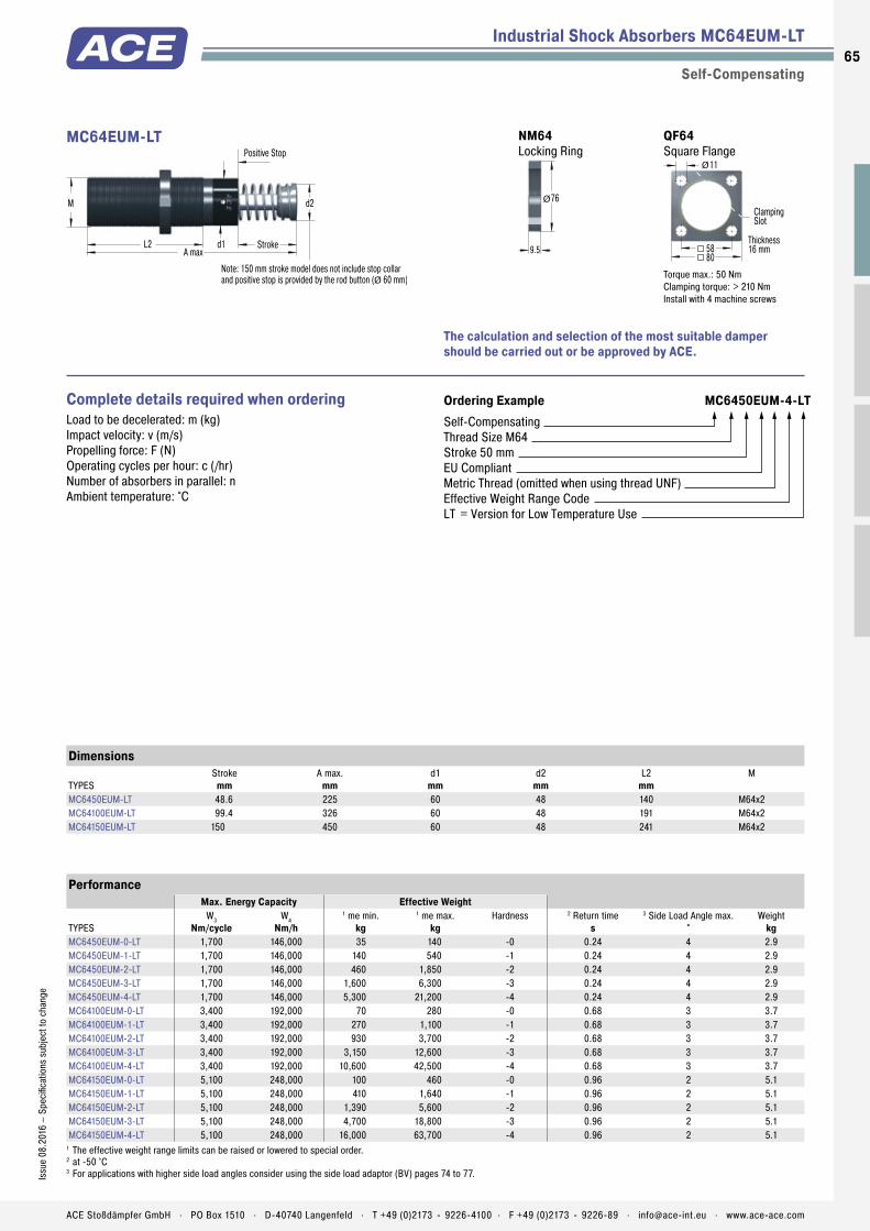
Industrial Shock Absorbers MC64EUM-LT
Self-Compensating
Ordering Example MC6450EUM-4-LTSelf-CompensatingThread Size M64Stroke 50 mmEU CompliantMetric Thread (omitted when using thread UNF)Effective Weight Range CodeLT = Version for Low Temperature Use
Complete details required when ordering Load to be decelerated: m (kg)Impact velocity: v (m/s)Propelling force: F (N)Operating cycles per hour: c (/hr)Number of absorbers in parallel: nAmbient temperature: °C
PerformanceMax. Energy Capacity Effective Weight
TYPESW3
Nm/cycleW4
Nm/h1 me min.
kg1 me max.
kgHardness 2 Return time
s3 Side Load Angle max.
°Weight
kgMC6450EUM-0-LT 1,700 146,000 35 140 -0 0.24 4 2.9MC6450EUM-1-LT 1,700 146,000 140 540 -1 0.24 4 2.9MC6450EUM-2-LT 1,700 146,000 460 1,850 -2 0.24 4 2.9MC6450EUM-3-LT 1,700 146,000 1,600 6,300 -3 0.24 4 2.9MC6450EUM-4-LT 1,700 146,000 5,300 21,200 -4 0.24 4 2.9MC64100EUM-0-LT 3,400 192,000 70 280 -0 0.68 3 3.7MC64100EUM-1-LT 3,400 192,000 270 1,100 -1 0.68 3 3.7MC64100EUM-2-LT 3,400 192,000 930 3,700 -2 0.68 3 3.7MC64100EUM-3-LT 3,400 192,000 3,150 12,600 -3 0.68 3 3.7MC64100EUM-4-LT 3,400 192,000 10,600 42,500 -4 0.68 3 3.7MC64150EUM-0-LT 5,100 248,000 100 460 -0 0.96 2 5.1MC64150EUM-1-LT 5,100 248,000 410 1,640 -1 0.96 2 5.1MC64150EUM-2-LT 5,100 248,000 1,390 5,600 -2 0.96 2 5.1MC64150EUM-3-LT 5,100 248,000 4,700 18,800 -3 0.96 2 5.1MC64150EUM-4-LT 5,100 248,000 16,000 63,700 -4 0.96 2 5.1
1 The effective weight range limits can be raised or lowered to special order.2 at -50 °C3 For applications with higher side load angles consider using the side load adaptor (BV) pages 74 to 77.
Dimensions
TYPESStroke
mmA max.
mmd1
mmd2
mmL2
mmM
MC6450EUM-LT 48.6 225 60 48 140 M64x2MC64100EUM-LT 99.4 326 60 48 191 M64x2MC64150EUM-LT 150 450 60 48 241 M64x2
d1
M
L2 Stroke
d2
A max
Positive Stop
Note: 150 mm stroke model does not include stop collar and positive stop is provided by the rod button (Ø 60 mm)
MC64EUM-LT QF64 Square Flange
80
Thickness16 mm
ClampingSlot
58
11Ø
Torque max.: 50 Nm Clamping torque: > 210 Nm Install with 4 machine screws
NM64 Locking Ring
9.5
76Ø
The calculation and selection of the most suitable damper should be carried out or be approved by ACE.
65Is
sue
08.2
016
– Sp
ecifi
catio
ns s
ubje
ct to
cha
nge
ACE Stoßdämpfer GmbH . PO Box 1510 . D-40740 Langenfeld . T +49 (0)2173 - 9226-4100 . F +49 (0)2173 - 9226-89 . [email protected] . www.ace-ace.com

Piston Rod
Membrane Accumulator
One-Piece Outer Body without Retaining Ring
Pressure Chamber with Metering Orifices
Rod Button
Seals
Piston Tube
Main Bearing
Outer Body
Return Spring
Check Valve
Locking Ring
Technical Data
True performers: The combination the proven sealing technology from the MAGNUM series including membrane accumulator with the well-known piston tube technology from the SC² family makes the SC33 to 45 absorber models so strong and durable. The increase of the oil volume ensures the maximum braking forces. Short stroke lengths of 25 to 50 mm lead to shorter braking times in combination with a high energy absorption.
These dampers safely and reliably decelerate rotary movements without unwanted recoil effects. Assembly close to the pivot point is possible. The low impact speeds with this are managed with ease by ACE‘s generation of piston tubes.
These self-compensating industrial shock absorbers can be relied on in mechanical engineering. They are used in pivot units, rotary tables, robot arms or integrated else where in construction designs.
SC33 to SC45Industrial Shock Absorbers Piston tube design for maximum energy absorption
Industrial Shock Absorbers
Self-Compensating, Piston Tube Technology
Energy capacity: 155 Nm/Cycle to 680 Nm/CycleImpact velocity range: 0.02 m/s to 0.46 m/s. Other speeds on request.Operating temperature range: -12 °C to +66 °C. Other temperatures on request.Mounting: In any positionPositive stop: In any positionMaterial: Outer body: Nitride hardened steel; Piston rod: Hard chrome plated steel; Rod end button: Hardened steel and corrosion-resistant coating; Accessories: Steel with black oxide fi nish or nitride hardened
Damping medium: Low temperature hydraulic oilApplication fi eld: Turntables, Swivel units, Robot arms, Linear slidesNote: A noise reduction of 3 to 7 dB is possible when using the special impact button (PP).Safety instructions: External materials in the surrounding area can attack the seal compo-nents and lead to a shorter service life. Please contact ACE for appropriate solution sugges-tions. Do not paint the shock absorbers due to heat emission.
On request: Special oils, mounting inside air cylinders or other special options are available on request.
66
Issu
e 08
.201
6 –
Spec
ifi ca
tions
sub
ject
to c
hang
e
ACE Stoßdämpfer GmbH . PO Box 1510 . D-40740 Langenfeld . T +49 (0)2173 - 9226-4100 . F +49 (0)2173 - 9226-89 . [email protected] . www.ace-ace.com
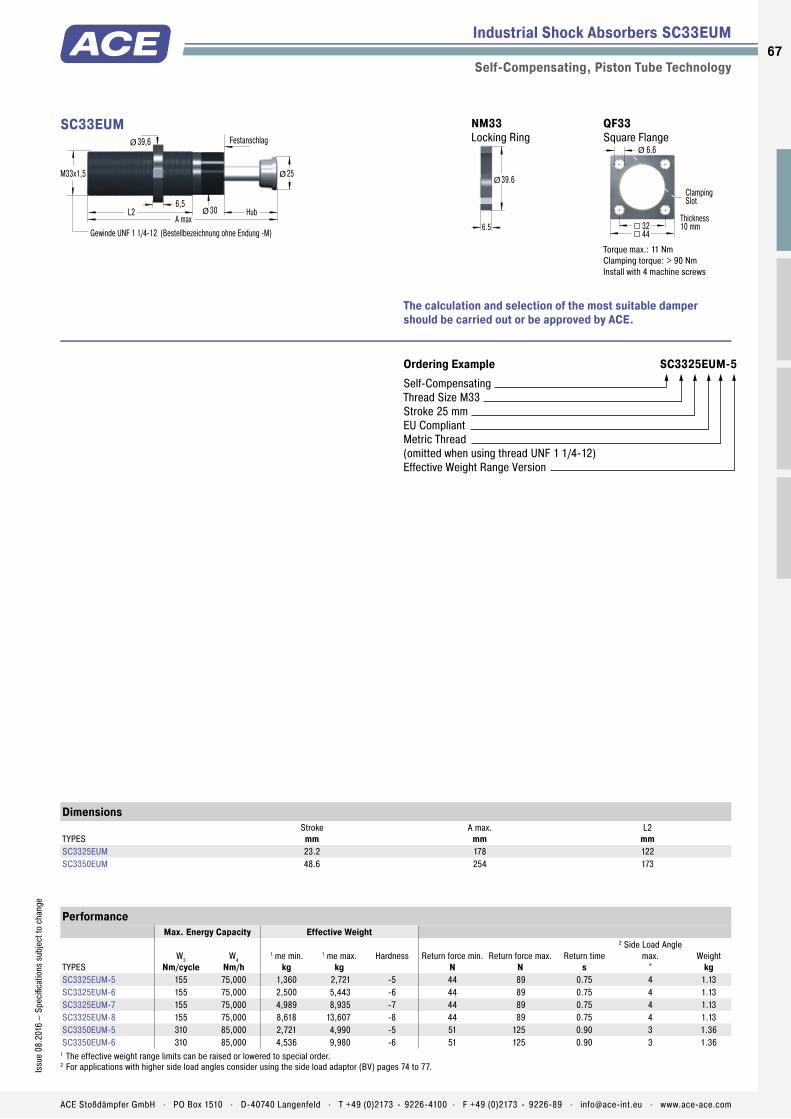
Piston Rod
Membrane Accumulator
One-Piece Outer Body without Retaining Ring
Pressure Chamber with Metering Orifices
Rod Button
Seals
Piston Tube
Main Bearing
Outer Body
Return Spring
Check Valve
Locking Ring
Industrial Shock Absorbers SC33EUM
Self-Compensating, Piston Tube Technology
Ordering Example SC3325EUM-5Self-CompensatingThread Size M33Stroke 25 mmEU CompliantMetric Thread(omitted when using thread UNF 1 1/4-12)Effective Weight Range Version
PerformanceMax. Energy Capacity Effective Weight
TYPESW3
Nm/cycleW4
Nm/h1 me min.
kg1 me max.
kgHardness Return force min.
NReturn force max.
NReturn time
s
2 Side Load Angle max.
°Weight
kgSC3325EUM-5 155 75,000 1,360 2,721 -5 44 89 0.75 4 1.13SC3325EUM-6 155 75,000 2,500 5,443 -6 44 89 0.75 4 1.13SC3325EUM-7 155 75,000 4,989 8,935 -7 44 89 0.75 4 1.13SC3325EUM-8 155 75,000 8,618 13,607 -8 44 89 0.75 4 1.13SC3350EUM-5 310 85,000 2,721 4,990 -5 51 125 0.90 3 1.36SC3350EUM-6 310 85,000 4,536 9,980 -6 51 125 0.90 3 1.36
1 The effective weight range limits can be raised or lowered to special order.2 For applications with higher side load angles consider using the side load adaptor (BV) pages 74 to 77.
Dimensions
TYPESStroke
mmA max.
mmL2
mmSC3325EUM 23.2 178 122SC3350EUM 48.6 254 173
30
M33x1,5
L2 Hub
25
A max
Festanschlag
Gewinde UNF 1 1/4-12 (Bestellbezeichnung ohne Endung -M)
Ø
39,6Ø
Ø
6,5
SC33EUM QF33 Square Flange
44
Thickness10 mm
ClampingSlot
32
6.6Ø
Torque max.: 11 NmClamping torque: > 90 NmInstall with 4 machine screws
NM33 Locking Ring
6.5
39.6Ø
The calculation and selection of the most suitable damper should be carried out or be approved by ACE.
67Is
sue
08.2
016
– Sp
ecifi
catio
ns s
ubje
ct to
cha
nge
ACE Stoßdämpfer GmbH . PO Box 1510 . D-40740 Langenfeld . T +49 (0)2173 - 9226-4100 . F +49 (0)2173 - 9226-89 . [email protected] . www.ace-ace.com

Industrial Shock Absorbers SC45EUM
Self-Compensating, Piston Tube Technology
Ordering Example SC4525EUM-5Self-CompensatingThread Size M45Stroke 25 mmEU CompliantMetric Thread(omitted when using thread UNF 1 3/4-12)Effective Weight Range Version
PerformanceMax. Energy Capacity Effective Weight
TYPESW3
Nm/cycleW4
Nm/h1 me min.
kg1 me max.
kgHardness Return force min.
NReturn force max.
NReturn time
s
2 Side Load Angle max.
°Weight
kgSC4525EUM-5 340 107,000 3,400 6,800 -5 67 104 0.8 4 1.27SC4525EUM-6 340 107,000 6,350 13,600 -6 67 104 0.8 4 1.27SC4525EUM-7 340 107,000 12,700 22,679 -7 67 104 0.8 4 1.27SC4525EUM-8 340 107,000 20,411 39,000 -8 67 104 0.8 4 1.27SC4550EUM-5 680 112,000 6,800 12,246 -5 47 242 1.0 3 1.49SC4550EUM-6 680 112,000 11,790 26,988 -6 47 242 1.0 3 1.49SC4550EUM-7 680 112,000 25,854 44,225 -7 47 242 1.0 3 1.49
1 The effective weight range limits can be raised or lowered to special order.2 For applications with higher side load angles consider using the side load adaptor (BV) pages 74 to 77.
Dimensions
TYPESStroke
mmA max.
mmL2
mmSC4525EUM 23.1 189 139SC4550EUM 48.5 265 190
42
M45x1.5
L2 Stroke
35
A max
Positive Stop
Thread UNF 1 3/4-12 also available on request (omit suffix -M from part number)
Ø
55.6Ø
Ø
9.5
SC45EUM QF45 Square Flange
56
Thickness12 mm
ClampingSlot
42
9Ø
Torque max.: 27 Nm Clamping torque: > 200 Nm Install with 4 machine screws
NM45 Locking Ring
9.5
55.6Ø
The calculation and selection of the most suitable damper should be carried out or be approved by ACE.
68
Issu
e 08
.201
6 –
Spec
ifica
tions
sub
ject
to c
hang
e
ACE Stoßdämpfer GmbH . PO Box 1510 . D-40740 Langenfeld . T +49 (0)2173 - 9226-4100 . F +49 (0)2173 - 9226-89 . [email protected] . www.ace-ace.com

NEW
ACE Sneak Preview
Pallet Stoppers pneumatic, hydraulic, electric
or combined version
For all information see our Website and the new Special Catalogue.
Autumn 2016
ACE Stoßdämpfer GmbH . PO Box 1510 . D-40740 Langenfeld . T +49 (0)2173 - 9226-4100 . [email protected] . www.ace-ace.com

Piston Rod
Membrane Accumulator
Return Spring
One-Piece Outer Body without Retaining Ring
Piston Ring
Pressure Chamber with Metering Orifices
Rod Button
Seals
Piston
Positive Stop
Main Bearing
Outer Body
Front Adjustment Segment
Rear Adjustment Segment
Locking Screw (MA/ML64)
Adjustment Chamber
Technical Data
Adjustable and unique: These industrial shock absorbers from ACE, which can be precisely adjusted both at the front and rear, also contribute towards the success of the MAGNUM series. Equipped with excellent sealing technology, an annealed guide bearing and integrated positive stop, they are robust and durable.
These dampers absorb 50 % more energy than their predecessors but are built even more compactly. The larger range of effective loads also opens up various options in design and assembly. This makes the ML series especially suitable for effective loads of 300 kg to 500,000 kg. Where work is done with changing application data and wherever fl exibility is required, they make the best option.
These adjustable industrial shock absorbers are used in all areas of mechanical engineering – e.g. in automation, integrated in linear carriages or pivoting units and also for gantries.
MA/ML33 to MA/ML64Industrial Shock Absorbers High energy absorption and progressive adjustment
Industrial Shock Absorbers
Adjustable
Energy capacity: 170 Nm/Cycle to 6,120 Nm/CycleImpact velocity range: MA: 0.15 m/s to 5 m/s. ML: 0.02 m/s to 0.46 m/s. Other speeds on request.Operating temperature range: -12 °C to +66 °COther temperatures on request.Mounting: In any positionPositive stop: IntegratedAdjustment: Hard impact at the start of stroke, adjust the ring towards 9 or PLUS. Hard impact at the end of stroke, adjust the ring towards 0 or MINUS.
Material: Outer body: Nitride hardened steel; Piston rod: Hard chrome plated steel; Rod end button: Hardened steel and corrosion-resistant coating; Return spring: Zinc plated or plastic-coated steel; Accessories: Steel with black oxide fi nish or nitride hardenedDamping medium: Automatic Transmission Fluid (ATF)Application fi eld: Linear slides, Swivel units, Turntables, Portal systemsNote: A noise reduction of 3 to 7 dB is possible when using the special impact button (PP). For emergency use only applications and for continous use (with additional cooling) it is sometimes possible to exceed the published
max. capacity ratings. In this case, please consult ACE.Safety instructions: External materials in the surrounding area can attack the seal compo-nents and lead to a shorter service life. Please contact ACE for appropriate solution sugges-tions. Do not paint the shock absorbers due to heat emission.On request: Special oils, nickel-plated, increased corrosion protection, mounting inside air cylinders or other special options are available on request.
70
Issu
e 08
.201
6 –
Spec
ifi ca
tions
sub
ject
to c
hang
e
ACE Stoßdämpfer GmbH . PO Box 1510 . D-40740 Langenfeld . T +49 (0)2173 - 9226-4100 . F +49 (0)2173 - 9226-89 . [email protected] . www.ace-ace.com
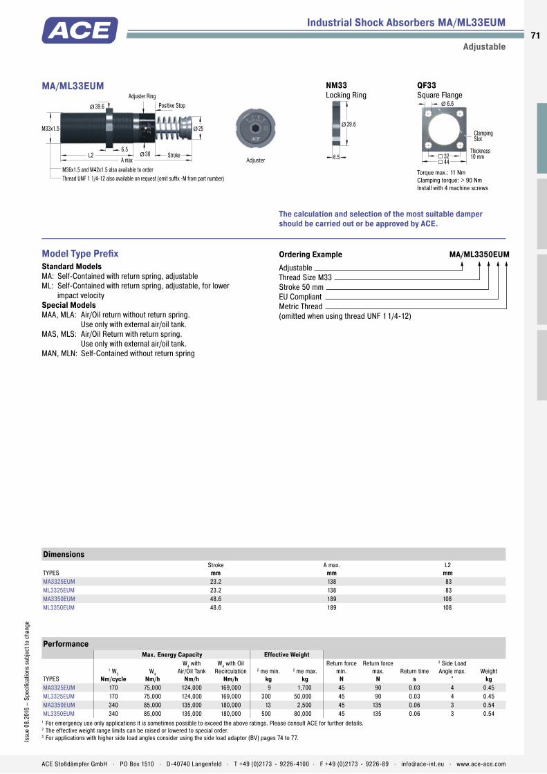
Piston Rod
Membrane Accumulator
Return Spring
One-Piece Outer Body without Retaining Ring
Piston Ring
Pressure Chamber with Metering Orifices
Rod Button
Seals
Piston
Positive Stop
Main Bearing
Outer Body
Front Adjustment Segment
Rear Adjustment Segment
Locking Screw (MA/ML64)
Adjustment Chamber
Industrial Shock Absorbers MA/ML33EUM
Adjustable
The calculation and selection of the most suitable damper should be carried out or be approved by ACE.
Ordering Example MA/ML3350EUMAdjustableThread Size M33Stroke 50 mmEU CompliantMetric Thread(omitted when using thread UNF 11/4-12)
Model Type Prefi xStandard ModelsMA: Self-Contained with return spring, adjustableML: Self-Contained with return spring, adjustable, for lower
impact velocity Special ModelsMAA, MLA: Air/Oil return without return spring.
Use only with external air/oil tank.MAS, MLS: Air/Oil Return with return spring.
Use only with external air/oil tank.MAN, MLN: Self-Contained without return spring
PerformanceMax. Energy Capacity Effective Weight
TYPES
1 W3Nm/cycle
W4Nm/h
W4 with Air/Oil Tank
Nm/h
W4 with Oil Recirculation
Nm/h2 me min.
kg2 me max.
kg
Return force min.
N
Return force max.
NReturn time
s
3 Side Load Angle max.
°Weight
kgMA3325EUM 170 75,000 124,000 169,000 9 1,700 45 90 0.03 4 0.45ML3325EUM 170 75,000 124,000 169,000 300 50,000 45 90 0.03 4 0.45MA3350EUM 340 85,000 135,000 180,000 13 2,500 45 135 0.06 3 0.54ML3350EUM 340 85,000 135,000 180,000 500 80,000 45 135 0.06 3 0.54
1 For emergency use only applications it is sometimes possible to exceed the above ratings. Please consult ACE for further details.2 The effective weight range limits can be raised or lowered to special order.3 For applications with higher side load angles consider using the side load adaptor (BV) pages 74 to 77.
Dimensions
TYPESStroke
mmA max.
mmL2
mmMA3325EUM 23.2 138 83ML3325EUM 23.2 138 83MA3350EUM 48.6 189 108ML3350EUM 48.6 189 108
30
M33x1.5
L2 Stroke
25
A max
Adjuster RingPositive Stop
M36x1.5 and M42x1.5 also available to orderThread UNF 1 1/4-12 also available on request (omit suffix -M from part number)
Ø
39.6Ø
Ø
6.5
Adjuster
MA/ML33EUM QF33 Square Flange
44
Thickness10 mm
ClampingSlot
32
6.6Ø
Torque max.: 11 NmClamping torque: > 90 NmInstall with 4 machine screws
NM33 Locking Ring
6.5
39.6Ø
71Is
sue
08.2
016
– Sp
ecifi
catio
ns s
ubje
ct to
cha
nge
ACE Stoßdämpfer GmbH . PO Box 1510 . D-40740 Langenfeld . T +49 (0)2173 - 9226-4100 . F +49 (0)2173 - 9226-89 . [email protected] . www.ace-ace.com

Industrial Shock Absorbers MA/ML45EUM
Adjustable
The calculation and selection of the most suitable damper should be carried out or be approved by ACE.
Ordering Example MA/ML4525EUMAdjustableThread Size M45Stroke 25 mmEU CompliantMetric Thread(omitted when using thread UNF 1 3/4-12)
Model Type PrefixStandard ModelsMA: Self-Contained with return spring, adjustableML: Self-Contained with return spring, adjustable, for lower
impact velocity Special ModelsMAA, MLA: Air/Oil return without return spring.
Use only with external air/oil tank.MAS, MLS: Air/Oil Return with return spring.
Use only with external air/oil tank.MAN, MLN: Self-Contained without return spring
PerformanceMax. Energy Capacity Effective Weight
TYPES
1 W3Nm/cycle
W4Nm/h
W4 with Air/Oil Tank
Nm/h
W4 with Oil Recirculation
Nm/h2 me min.
kg2 me max.
kg
Return force min.
N
Return force max.
NReturn time
s
3 Side Load Angle max.
°Weight
kgMA4525EUM 390 107,000 158,000 192,000 40 10,000 70 100 0.03 4 1.13ML4525EUM 390 107,000 158,000 192,000 3,000 110,000 70 100 0.03 4 1.13MA4550EUM 780 112,000 192,000 248,000 70 14,500 70 145 0.08 3 1.36ML4550EUM 780 112,000 192,000 248,000 5,000 180,000 70 145 0.08 3 1.36MA4575EUM 1,170 146,000 225,000 282,000 70 15,000 50 180 0.11 2 1.59
1 For emergency use only applications it is sometimes possible to exceed the above ratings. Please consult ACE for further details.2 The effective weight range limits can be raised or lowered to special order.3 For applications with higher side load angles consider using the side load adaptor (BV) pages 74 to 77.
Dimensions
TYPESStroke
mmA max.
mmL2
mmMA4525EUM 23.1 145 95ML4525EUM 23.1 145 95MA4550EUM 48.5 195 120ML4550EUM 48.5 195 120MA4575EUM 73.9 246 145
42
M45x1.5
L2 Stroke
35
A max
Adjuster RingPositive Stop
Thread UNF 1 3/4-12 also available on request (omit suffix -M from part number)
Ø
57.2Ø
Ø
9.5
Adjuster
MA/ML45EUM QF45 Square Flange
56
Thickness12 mm
ClampingSlot
42
9Ø
Torque max.: 27 Nm Clamping torque: > 200 Nm Install with 4 machine screws
NM45 Locking Ring
9.5
55.6Ø
72
Issu
e 08
.201
6 –
Spec
ifica
tions
sub
ject
to c
hang
e
ACE Stoßdämpfer GmbH . PO Box 1510 . D-40740 Langenfeld . T +49 (0)2173 - 9226-4100 . F +49 (0)2173 - 9226-89 . [email protected] . www.ace-ace.com
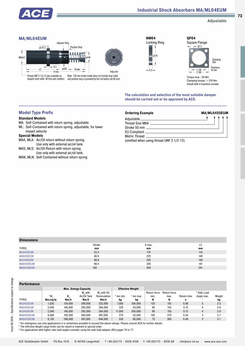
Industrial Shock Absorbers MA/ML64EUM
Adjustable
The calculation and selection of the most suitable damper should be carried out or be approved by ACE.
Ordering Example MA/ML6450EUMAdjustable Thread Size M64 Stroke 50 mm EU Compliant Metric Thread(omitted when using thread UNF 2 1/2-12)
Model Type PrefixStandard ModelsMA: Self-Contained with return spring, adjustableML: Self-Contained with return spring, adjustable, for lower
impact velocity Special ModelsMAA, MLA: Air/Oil return without return spring.
Use only with external air/oil tank.MAS, MLS: Air/Oil Return with return spring.
Use only with external air/oil tank.MAN, MLN: Self-Contained without return spring
PerformanceMax. Energy Capacity Effective Weight
TYPES
1 W3Nm/cycle
W4Nm/h
W4 with Air/Oil Tank
Nm/h
W4 with Oil Recirculation
Nm/h2 me min.
kg2 me max.
kg
Return force min.
N
Return force max.
NReturn time
s
3 Side Load Angle max.
°Weight
kgML6425EUM 1,020 124,000 248,000 332,000 7,000 300,000 120 155 0.06 5 2.5MA6450EUM 2,040 146,000 293,000 384,000 220 50,000 90 155 0.12 4 2.9ML6450EUM 2,040 146,000 293,000 384,000 11,000 500,000 90 155 0.12 4 2.9MA64100EUM 4,080 192,000 384,000 497,000 270 52,000 105 270 0.34 3 3.7MA64150EUM 6,120 248,000 497,000 644,000 330 80,000 75 365 0.48 2 5.1
1 For emergency use only applications it is sometimes possible to exceed the above ratings. Please consult ACE for further details.2 The effective weight range limits can be raised or lowered to special order.3 For applications with higher side load angles consider using the side load adaptor (BV) pages 74 to 77.
Dimensions
TYPESStroke
mmA max.
mmL2
mmML6425EUM 23.2 174 114MA6450EUM 48.6 225 140ML6450EUM 48.6 225 140MA64100EUM 99.4 326 191MA64150EUM 150 450 241
60
M64x2
L2 Stroke
48
A max
Adjuster RingPositive Stop
Thread UNF 2 1/2-12 also available onrequest (omit suffix -M from part number)
Ø
Ø
9.5
Note: 150 mm stroke model does not include stop collar and positive stop is provided by the rod button (Ø 60 mm)
Adjuster
76.2Ø
MA/ML64EUM QF64 Square Flange
80
Thickness16 mm
ClampingSlot
58
11Ø
Torque max.: 50 Nm Clamping torque: > 210 Nm Install with 4 machine screws
NM64 Locking Ring
9.5
76Ø
73Is
sue
08.2
016
– Sp
ecifi
catio
ns s
ubje
ct to
cha
nge
ACE Stoßdämpfer GmbH . PO Box 1510 . D-40740 Langenfeld . T +49 (0)2173 - 9226-4100 . F +49 (0)2173 - 9226-89 . [email protected] . www.ace-ace.com

Industrial Shock Absorber Accessories M33 to M64
Overview
Mounting, installation, ... see page 77.
M33x1.5
L1 L31020max
min
8
742
56
20
Ø
40
Dimensions
TYPESL1 min.
mmL1 max.
mmL3
mmMC, MA, ML3325EUM 25 60 68MC, MA, ML3350EUM 32 86 93SC3325EUM 40 98 66SC3350EUM 60 153 92
S33 Side Foot Mounting Kit
S33 = 2 fl anges + 4 screws M6x40, DIN 912Torque max.: 11 NmClamping torque: 90 NmBecause of the thread pitch the fi xing holes for the second foot mount should only be drilled and tapped after the fi rst foot mount has been fi xed in position.
13 thick
L6 max38
13 thickL5 max
R10
1414
13 13
14
min20°
min 10°
10H8 10H8
Ø
Dimensions
TYPESL5 max.
mmL6 max.
mmMC, MA, ML3325EUM 39 168MC, MA, ML3350EUM 64 218SC3325EUM 39 208SC3350EUM 64 283
C33 Clevis Mounting Kit
C33 = 2 clevis eyes. Delivered assembled to shock absorber.Use positive stop at both ends of travel.
10h9
3414
3245
H14
Ø
PinRetainer
7
22
13
5
23
Ø
SF33 Clevis Flange
SF33 = fl ange + 4 screws M6x20, DIN 912Torque max.: 7.5 NmClamping torque: > 50 NmSecure with pin or use additional bar. Due to limited force capacity the respective ability should be reviewed by ACE.
M33x1.5
NM33 Locking Ring
6.5
39.6Ø
PP33 Poly Button
29.2
13.2A max
see shock absorber dims.
Ø
Supplied ready mounted onto the shock absorber.
QF33 Square Flange
44
Thickness10 mm
ClampingSlot
32
6.6Ø
Torque max.: 11 NmClamping torque: > 90 NmInstall with 4 machine screws
AS33 Switch Stop Collar
37Ø
24
56A max see shock absorber dims.
13.2
inc. Proximity Switch and Poly Button with elastomer insert
BV3325 Side Load Adaptor
M33x1.5 Stroke23
4829
M45x1.5
100
30
max.25°
Ø
BV3350 Side Load Adaptor
M33x1.5 Stroke48.5
7553.5
M45x1.5
128
30
max.25°
Ø
PB3325 Steel Shroud
Stroke
15
35
3725
1 A max 148
Ø
Ø
1 Total installation length of the shock absorber inc. steel shroud
PB3350 Steel Shroud
Stroke
15
36
61.550
1 A max 198
Ø
Ø
1 Total installation length of the shock absorber inc. steel shroud
74
Issu
e 08
.201
6 –
Spec
ifi ca
tions
sub
ject
to c
hang
e
ACE Stoßdämpfer GmbH . PO Box 1510 . D-40740 Langenfeld . T +49 (0)2173 - 9226-4100 . F +49 (0)2173 - 9226-89 . [email protected] . www.ace-ace.com

NM45 Locking Ring
9.5
55.6Ø
PP45 Poly Button
42
19.4A max
see shock absorber dims.
Ø
Supplied ready mounted onto the shock absorber.
QF45 Square Flange
56
Thickness12 mm
ClampingSlot
42
9Ø
Torque max.: 27 NmClamping torque: > 200 NmInstall with 4 machine screws
AS45 Switch Stop Collar
57Ø
30
55.5A max see shock absorber dims.
19.4
inc. Proximity Switch and Poly Button with elastomer insert
BV4525 Side Load Adaptor
M45x1.5 Stroke23
5229
M64x2
100
40
max.20°
Ø
Industrial Shock Absorber Accessories M33 to M64
Overview
Mounting, installation, ... see page 77.
M45x1.5
L1 L312.5
25maxmin
16
960
80
28
Ø
56
Dimensions
TYPESL1 min.
mmL1 max.
mmL3
mmMC, MA, ML4525EUM 32 66 66MC, MA, ML4550EUM 40 91MC, MA4575EUM 50 118 116SC4525EUM 50 112 62.5SC4550EUM 64 162 87.5
S45 Side Foot Mounting Kit
S45 = 2 fl anges + 4 screws M8x50, DIN 912Torque max.: 27 NmClamping torque: 350 NmBecause of the thread pitch the fi xing holes for the second foot mount should only be drilled and tapped after the fi rst foot mount has been fi xed in position.
20 thick
L6 max53
20 thickL5 max
R14
2028
20 17
18
min15°
min 15°
16H8 16H8
Ø
Dimensions
TYPESL5 max.
mmL6 max.
mmMC, MA, ML4525EUM 43 200MC, MA, ML4550EUM 68 250MC, MA4575EUM 93 301SC4525EUM 68 244SC4550EUM 93 320
C45 Clevis Mounting Kit
C45 = 2 clevis eyes. Delivered assembled to shock absorber.Use positive stop at both ends of travel.
16h9
4521
4665
H14
Ø
PinRetainer
9
27
15
6
29
Ø
SF45 Clevis Flange
SF45 = fl ange + 4 screws M8x20, DIN 912Torque max.: 7.5 NmClamping torque: > 140 NmSecure with pin or use additional bar. Due to limited force capacity the respective ability should be reviewed by ACE.
M45x1.5
BV4550 Side Load Adaptor
M45x1.5 Stroke48.5
8054.5
M64x2
130
40
max.20°
Ø
PB4525 Steel Shroud
Stroke
20
48
3725
1 A max 154
Ø
Ø
1 Total installation length of the shock absorber inc. steel shroud
PB4550 Steel Shroud
Stroke
20
48
62.550
1 A max 204.5
Ø
Ø
1 Total installation length of the shock absorber inc. steel shroud
75Is
sue
08.2
016
– Sp
ecifi
catio
ns s
ubje
ct to
cha
nge
ACE Stoßdämpfer GmbH . PO Box 1510 . D-40740 Langenfeld . T +49 (0)2173 - 9226-4100 . F +49 (0)2173 - 9226-89 . [email protected] . www.ace-ace.com

Industrial Shock Absorber Accessories M33 to M64
Overview
Mounting, installation, ... see page 77.
M64x2
L1 L312.5
25maxmin
12
11.578
100
40
Ø
80
Dimensions
TYPESL1 min.
mmL1 max.
mmL3
mmML6425EUM 40 86 75.5MC, MA, ML6450EUM 50 112 100MC, MA64100EUM 4 162 152MC, MA64150EUM 80 212 226
S64 Side Foot Mounting Kit
S64 = 2 fl anges + 4 screws M10x80, DIN 912Torque max.: 50 NmClamping torque: 350 NmBecause of the thread pitch the fi xing holes for the second foot mount should only be drilled and tapped after the fi rst foot mount has been fi xed in position.
Dimensions
TYPESL5 max.
mmL6 max.
mmML6425EUM 60 260MC, MA, ML6450EUM 85 310MC, MA64100EUM 136 410MC, MA64150EUM 187 530
24 thick
L6 max74
24 thickL5 max
R20
2535
30 30
35
min20°
min 10°
20H8 20H8
Ø Ø 501
1 With 150 mm stroke Dia. 60 mm. Order C64-150.
C64 Clevis Mounting Kit
C64 = 2 clevis eyes. Delivered assembled to shock absorber.1 with 150 mm stroke Dia. 60 mm. Order C64-150.Use positive stop at both ends of travel.
20h9
6525
7295
H14
Ø
PinRetainer
11
36
22
10
45
Ø
SF64 Clevis Flange
SF64 = fl ange + 4 screws M10x20, DIN 912Torque max.: 15 NmClamping torque: > 200 NmSecure with pin or use additional bar. Due to limited force capacity the respective ability should be reviewed by ACE.
M64x2
NM64 Locking Ring
9.5
76Ø
PP64 Poly Button
60
19.1A max
see shock absorber dims.
Ø
Supplied ready mounted onto the shock absorber.
QF64 Square Flange
80
Thickness16 mm
ClampingSlot
58
11Ø
Torque max.: 50 NmClamping torque: > 210 NmInstall with 4 machine screws
QF90 Square Flange
110
Thickness20 mm
ClampingSlot
80
11Ø
Torque max.: 50 NmClamping torque: > 210 NmInstall with 4 machine screws
BV6425 Side Load Adaptor
M64x2 Stroke23
10030
M90x2
170
56
max.20°
Ø
BV6450 Side Load Adaptor
M64x2 Stroke48.5
10055
M90x2
170
56
max.20°
Ø
PB6425 Steel Shroud
Stroke
30
67
4025
1 A max 184.5
Ø
Ø
1 Total installation length of the shock absorber inc. steel shroud
PB6450 Steel Shroud
Stroke
30
67
6950
1 A max 236
Ø
Ø
1 Total installation length of the shock absorber inc. steel shroud
76
Issu
e 08
.201
6 –
Spec
ifi ca
tions
sub
ject
to c
hang
e
ACE Stoßdämpfer GmbH . PO Box 1510 . D-40740 Langenfeld . T +49 (0)2173 - 9226-4100 . F +49 (0)2173 - 9226-89 . [email protected] . www.ace-ace.com

Industrial Shock Absorber Accessories from M33x1.5
Technical Information
Shock Absorber Threaded Body Plunger
Positive Stop
BV Side Load AdaptorFor side load impact angles from 3° to 25°With side load impact angles of more than 3° the operation lifetime of the shock absorber reduces rapidly due to increased wear of rod bearings. The optional BV side load adaptor provides long lasting solution.Ordering information BV3325 (M45x1.5) for MC, MA, ML3325EUM (M33x1.5) BV3350 (M45x1.5) for MC, MA, ML3350EUM (M33x1.5) BV4525 (M64x2) for MC, MA, ML4525EUM (M45x1.5) BV4550 (M64x2) for MC, MA, ML4550EUM (M45x1.5) BV6425 (M90x2) for ML6425EUM (M64x2) BV6450 (M90x2) for MC, MA, ML6450EUM (M64x2)Material Threaded body and plunger: Hardened high tensile steel, hardened 610 HV1Mounting information Directly mount the shock absorber/side mount assembly on the outside thread of the side load adaptor or by using the QF flange. You cannot use a foot mount.Calculation example and installation hints see page 45.
Shock Absorber
Stroke
Steel Shroud
Positive StopPB Steel Shroud
For thread sizes M33x1.5, M45x1.5 and M64x2 with 25 or 50 mm stroke. Grinding beads, sand, welding splatter, paints and adhesives etc. can adhere to the piston rod. They then damage the rod seals and the shock absorber quickly fails. In many cases the installation of the optional steel shroud can provide worthwhile protection and increase lifetime.Material Hardened high tensile steelMounting information To mount the PB steel shroud it is necessary to remove the rod end button of the shock absorber.Safety instructions When installing don’t forget to allow operating space for the shroud to move as the shock absorber is cycled.
Shock Absorber Switch Stop Collar
Positive Stop
Steel Button with Elastomer Insert
Proximity SwitchAS Switch Stop Collar
For thread sizes M33x1.5 and M45x1.5 The ACE stop light switch stop collar combination serves as a safety element to provide stroke position information for automatically sequenced machines. The compact construction allows its use in nearly any application. The standard rod button is detected by the proximity switch at the end of its stroke to provide switch actuation. The switch is normally open when the shock absorber is extended and only closes when it has completed its operating stroke.Material Hardened high tensile steelDelivery The AS switch stop collar combination is only delivered ready mounted onto the shock absorber c/w the switch.For circuit diagram of proximity switch see page 46.
77Is
sue
08.2
016
– Sp
ecifi
catio
ns s
ubje
ct to
cha
nge
ACE Stoßdämpfer GmbH . PO Box 1510 . D-40740 Langenfeld . T +49 (0)2173 - 9226-4100 . F +49 (0)2173 - 9226-89 . [email protected] . www.ace-ace.com
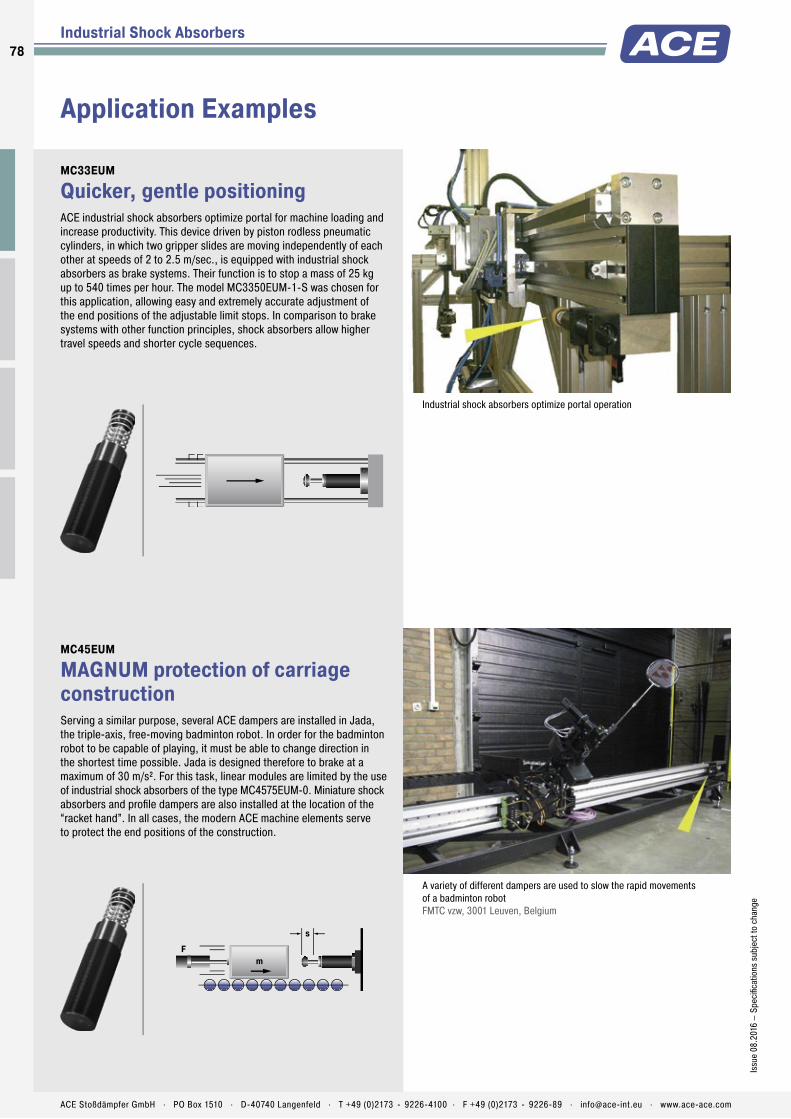
Application Examples
Industrial Shock Absorbers
MC33EUM
Quicker, gentle positioningACE industrial shock absorbers optimize portal for machine loading and increase productivity. This device driven by piston rodless pneumatic cylinders, in which two gripper slides are moving independently of each other at speeds of 2 to 2.5 m/sec., is equipped with industrial shock absorbers as brake systems. Their function is to stop a mass of 25 kg up to 540 times per hour. The model MC3350EUM-1-S was chosen for this application, allowing easy and extremely accurate adjustment of the end positions of the adjustable limit stops. In comparison to brake systems with other function principles, shock absorbers allow higher travel speeds and shorter cycle sequences.
Industrial shock absorbers optimize portal operation
MC45EUM
MAGNUM protection of carriage constructionServing a similar purpose, several ACE dampers are installed in Jada, the triple-axis, free-moving badminton robot. In order for the badminton robot to be capable of playing, it must be able to change direction in the shortest time possible. Jada is designed therefore to brake at a maximum of 30 m/s². For this task, linear modules are limited by the use of industrial shock absorbers of the type MC4575EUM-0. Miniature shock absorbers and profi le dampers are also installed at the location of the “racket hand”. In all cases, the modern ACE machine elements serve to protect the end positions of the construction.
s
mF
A variety of different dampers are used to slow the rapid movements of a badminton robot FMTC vzw, 3001 Leuven, Belgium
78
Issu
e 08
.201
6 –
Spec
ifi ca
tions
sub
ject
to c
hang
e
ACE Stoßdämpfer GmbH . PO Box 1510 . D-40740 Langenfeld . T +49 (0)2173 - 9226-4100 . F +49 (0)2173 - 9226-89 . [email protected] . www.ace-ace.com
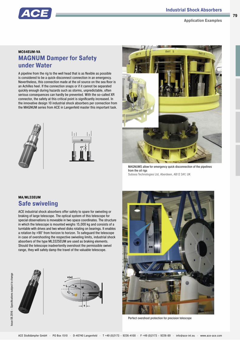
Industrial Shock Absorbers
Application Examples
MC64EUM-VA
MAGNUM Damper for Safety under WaterA pipeline from the rig to the well head that is as fl exible as possible is considered to be a quick-disconnect connection in an emergency. Nevertheless, this connection made at the oil source on the sea fl oor is an Achilles heel. If the connection snaps or if it cannot be separated quickly enough during hazards such as storms, unpredictable, often serious consequences can hardly be prevented. With the so-called XR connector, the safety at this critical point is signifi cantly increased. In the innovative design 10 industrial shock absorbers per connection from the MAGNUM series from ACE in Langenfeld master this important task.
s
m
MAGNUMS allow for emergency quick disconnection of the pipelines from the oil rigs Subsea Technologies Ltd, Aberdeen, AB12 3AY, UK
MA/ML33EUM
Safe swivelingACE industrial shock absorbers offer safety to spare for swiveling or braking of large telescope. The optical system of this telescope for special observations is moveable in two space coordinates. The structure in which the telescope is mounted weighs 15,000 kg and consists of a turntable with drives and two wheel disks rotating on bearings. It enables a rotation by ±90° from horizon to horizon. To safeguard the telescope in case of overshooting the respective swiveling limits, industrial shock absorbers of the type ML3325EUM are used as braking elements. Should the telescope inadvertently overshoot the permissible swivel range, they will safely damp the travel of the valuable telescope.
s
mMRL
vD
v(ω)
Perfect overshoot protection for precision telescope
79Is
sue
08.2
016
– Sp
ecifi
catio
ns s
ubje
ct to
cha
nge
ACE Stoßdämpfer GmbH . PO Box 1510 . D-40740 Langenfeld . T +49 (0)2173 - 9226-4100 . F +49 (0)2173 - 9226-89 . [email protected] . www.ace-ace.com

Automation Control
The heavy industrial shock absorbers from ACE round off the top of the company‘s offers in damping technology. Designers also have the choice between self-compensating and adjustable machine elements in this category from ACE.
Whichever design is chosen, this type of shock absorber impresses with its robustness and operational readiness wherever heavy loads need reliably stopped on-the-spot at a precise point.
The CA4 models can absorb up to 126,500 Nm of energy. The series of heavy duty, self-compensating CA types are equally suitable for use as an emergency stop as the adjustable types with the designations A1 to A3. The range of effective loads covered is increased considerably for this purpose.
Heavy Industrial Shock AbsorbersEffective shock absorption for heavy loads
8080
ACE Stoßdämpfer GmbH . PO Box 1510 . D-40740 Langenfeld . T +49 (0)2173 - 9226-4100 . [email protected] . www.ace-ace.com

Product Families
Overview
Heavy Industrial Shock Absorbers
CA2 to CA4 Self-Compensating Deceleration of heavy loadsPortal systems, Machines and plants, Conveyor systems, Crane systems
Page 82
A1½ to A3 Adjustable Deceleration of heavy loads and progressive adjustmentPortal systems, Machines and plants, Conveyor systems, Crane systems
Page 86
Rugged and powerful
Gently stops heavy loads with high precision
Also ideal for emergency stop utilisation
Safe, reliable production
Maintenance-free and ready-to-install
Special versions available
81
ACE Stoßdämpfer GmbH . PO Box 1510 . D-40740 Langenfeld . T +49 (0)2173 - 9226-4100 . F +49 (0)2173 - 9226-89 . [email protected] . www.ace-ace.com

Piston Rod
Return Spring
Pressure Chamber with Metering Orifices
Rod Button
Seals
Piston
Main Bearing
Outer Body
Piston Ring
Accumulator
Technical Data
Powerful: The mass of these high volume absorbers are between 12.8 and 146 kg in weight. They complement ACE‘s product range of self-compensating shock absorbers. All models from this series are designed for applications where robustness and a large energy absorption are important.
The absorbers are designed specifi cally for each customer application with the aid of the ACE calculation program. The risk of crashes and incorrect settings are therefore prevented The CA models can absorb up to 126,500 Nm of energy and can be used in the area of effective loads between 700 kg and 326,000 kg. The combination of being extremely solid, absorbing high levels of energy and having a large damping range makes them invaluable.
These heavy duty self-compensating industrial shock absorbers are primarily used in heavy mechanical engineering e.g. on lift bridges and steel structures or for damping sluice systems.
CA2 to CA4Heavy Industrial Shock Absorbers Deceleration of heavy loads
Heavy Industrial Shock Absorbers
Self-Compensating
Energy capacity: 3,600 Nm/Cycle to 126,500 Nm/CycleImpact velocity range: 0.3 m/s to 5 m/s. Other speeds on request.Operating temperature range: -12 °C to +66 °C. Other temperatures on request.Mounting: In any positionPositive stop: External positive stops 2.5 mm to 3 mm before the end of stroke provided by the customer.Material: Outer body: Steel corrosion-resistant coating; Piston rod: Hard chrome plated steel; Rod end button: Hardened
steel and corrosion-resistant coating; Return spring: Zinc plated steelDamping medium: Automatic Transmission Fluid (ATF)Application fi eld: Portal systems, Machines and plants, Conveyor systems, Crane systemsNote: For emergency use only applications and for continous use it is possible to exceed the published max. capacity ratings. In this case, please consult ACE.Safety instructions: External materials in the surrounding area can attack the seal components and lead to a shorter service life. Please contact ACE for appropriate solution
suggestions. Do not paint the shock absorbers due to heat emission.On request: Special oils, nickel-plated, increased corrosion protection or other special options are available on request.
82
Issu
e 08
.201
6 –
Spec
ifi ca
tions
sub
ject
to c
hang
e
ACE Stoßdämpfer GmbH . PO Box 1510 . D-40740 Langenfeld . T +49 (0)2173 - 9226-4100 . F +49 (0)2173 - 9226-89 . [email protected] . www.ace-ace.com

Piston Rod
Return Spring
Pressure Chamber with Metering Orifices
Rod Button
Seals
Piston
Main Bearing
Outer Body
Piston Ring
Accumulator
The calculation and selection of the most suitable damper should be carried out or be approved by ACE.
PerformanceMax. Energy Capacity Effective Weight
TYPES
1 W3Nm/cycle
2 W4Nm/h
2 W4 with Air/Oil Tank
Nm/h3 me min.
kg3 me max.
kgHardness
Return force min.
N
Return force max.
NReturn time
s
Side Load Angle max.
°Weight
kgCA2X2EU-1 3,600 1,100,000 1,350,000 700 2,200 -1 210 285 0.25 3 12.80CA2X2EU-2 3,600 1,100,000 1,350,000 1,800 5,400 -2 210 285 0.25 3 14.29CA2X2EU-3 3,600 1,100,000 1,350,000 4,500 13,000 -3 210 285 0.25 3 12.80CA2X2EU-4 3,600 1,100,000 1,350,000 11,300 34,000 -4 210 285 0.25 3 14.29CA2X4EU-1 7,200 1,350,000 1,700,000 1,400 4,400 -1 150 285 0.50 3 16.74CA2X4EU-2 7,200 1,350,000 1,700,000 3,600 11,000 -2 150 285 0.50 3 16.74CA2X4EU-3 7,200 1,350,000 1,700,000 9,100 27,200 -3 150 285 0.50 3 16.74CA2X4EU-4 7,200 1,350,000 1,700,000 22,600 68,000 -4 150 285 0.50 3 16.74CA2X6EU-1 10,800 1,600,000 2,000,000 2,200 6,500 -1 150 400 0.60 3 19.32CA2X6EU-2 10,800 1,600,000 2,000,000 5,400 16,300 -2 150 400 0.60 3 19.32CA2X6EU-3 10,800 1,600,000 2,000,000 13,600 40,800 -3 150 400 0.60 3 19.32CA2X6EU-4 10,800 1,600,000 2,000,000 34,000 102,000 -4 150 400 0.60 3 19.32CA2X8EU-1 14,500 1,900,000 2,400,000 2,900 8,700 -1 230 650 0.70 3 22.27CA2X8EU-2 14,500 1,900,000 2,400,000 7,200 21,700 -2 230 650 0.70 3 22.27CA2X8EU-3 14,500 1,900,000 2,400,000 18,100 54,400 -3 230 650 0.70 3 22.27CA2X8EU-4 14,500 1,900,000 2,400,000 45,300 136,000 -4 230 650 0.70 3 22.27CA2X10EU-1 18,000 2,200,000 2,700,000 3,600 11,000 -1 160 460 0.80 3 32.30CA2X10EU-2 18,000 2,200,000 2,700,000 9,100 27,200 -2 160 460 0.80 3 32.30CA2X10EU-3 18,000 2,200,000 2,700,000 22,600 68,000 -3 160 460 0.80 3 32.30CA2X10EU-4 18,000 2,200,000 2,700,000 56,600 170,000 -4 160 460 0.80 3 32.30
1 For emergency use only applications it is sometimes possible to exceed the above ratings. Please consult ACE for further details.2 Figures for oil recirculation systems on request.3 The effective weight range limits can be raised or lowered to special order.
Dimensions
TYPESStroke
mmA max.
mmB max.
mmC
mmD max.
mmE
mmCA2X2EU 50 313 110 173 125 70CA2X4EU 102 414 160 224 175 70CA2X6EU 152 516 211 275 226 70CA2X8EU 203 643 287 326 302 92CA2X10EU 254 745 338 377 353 108
Ordering Example CA2x4EU-3FSelf-CompensatingBore Size Ø 2"Stroke Length 4" = 102 mmEU CompliantEffective Weight Range VersionFront Flange Mounting
Model Type Prefi xStandard ModelsCA: Self-contained with return spring, self-compensatingSpecial ModelsCAA: Air/Oil return without return spring.
Use only with external air/oil tank. CNA: Self-Contained without return springCSA: Air/Oil return with return spring.
Use only with external air/oil tank.
Heavy Industrial Shock Absorbers CA2EU
Self-Compensating
A max19 19 B max
Ø 108
M100x2
Ø 35
E
Stroke
140
17
111
Ø
CA2EU-F Front Flange
A max
19Stroke
19 B max
Ø 35
E
Ø 108
M100x2
140
17
111
Ø
CA2EU-R Rear Flange
C32 15
D max15
Ø 35
E
Ø 108 Stroke
60
6036
160190
Ø18
CA2EU-SM Foot Mount
Clevis mounting available on request.
83Is
sue
08.2
016
– Sp
ecifi
catio
ns s
ubje
ct to
cha
nge
ACE Stoßdämpfer GmbH . PO Box 1510 . D-40740 Langenfeld . T +49 (0)2173 - 9226-4100 . F +49 (0)2173 - 9226-89 . [email protected] . www.ace-ace.com

The calculation and selection of the most suitable damper should be carried out or be approved by ACE.
PerformanceMax. Energy Capacity Effective Weight
TYPES
1 W3Nm/cycle
2 W4Nm/h
2 W4 with Air/Oil Tank
Nm/h3 me min.
kg3 me max.
kgHardness
Return force min.
N
Return force max.
NReturn time
s
Side Load Angle max.
°Weight
kgCA3X5EU-1 14,125 2,260,000 2,800,000 2,900 8,700 -1 270 710 0.6 3 32.70CA3X5EU-2 14,125 2,260,000 2,800,000 7,250 21,700 -2 270 710 0.6 3 32.70CA3X5EU-3 14,125 2,260,000 2,800,000 18,100 54,350 -3 270 710 0.6 3 32.70CA3X5EU-4 14,125 2,260,000 2,800,000 45,300 135,900 -4 270 710 0.6 3 32.70CA3X8EU-1 22,600 3,600,000 4,520,000 4,650 13,900 -1 280 740 0.8 3 38.51CA3X8EU-2 22,600 3,600,000 4,520,000 11,600 34,800 -2 280 740 0.8 3 38.51CA3X8EU-3 22,600 3,600,000 4,520,000 29,000 87,000 -3 280 740 0.8 3 33.40CA3X8EU-4 22,600 3,600,000 4,520,000 72,500 217,000 -4 280 740 0.8 3 38.51CA3X12EU-1 33,900 5,400,000 6,780,000 6,950 20,900 -1 270 730 1.2 3 47.63CA3X12EU-2 33,900 5,400,000 6,780,000 17,400 52,200 -2 270 730 1.2 3 47.63CA3X12EU-3 33,900 5,400,000 6,780,000 43,500 130,450 -3 270 730 1.2 3 47.63CA3X12EU-4 33,900 5,400,000 6,780,000 108,700 326,000 -4 270 730 1.2 3 47.63
1 For emergency use only applications it is sometimes possible to exceed the above ratings. Please consult ACE for further details.2 Figures for oil recirculation systems on request.3 The effective weight range limits can be raised or lowered to special order.
Dimensions
TYPESStroke
mmA max.
mmB max.
mmC
mmD max.
mmCA3X5EU 127 490.5 211 254 224CA3X8EU 203 641 286 330 300CA3X12EU 305 890 434 432 447
Ordering Example CA3x5EU-3FSelf-CompensatingBore Size Ø 3"Stroke Length 5" = 127 mmEU CompliantEffective Weight Range VersionFront Flange Mounting
Model Type Prefi xStandard ModelsCA: Self-contained with return spring, self-compensatingSpecial ModelsCAA: Air/Oil return without return spring.
Use only with external air/oil tank. CNA: Self-Contained without return springCSA: Air/Oil return with return spring.
Use only with external air/oil tank.
Heavy Industrial Shock Absorbers CA3EU
Self-Compensating
A max25 25 B max
Ø 140
M130x2 112
Ø 44.5
Stroke
165
17
136.5
Ø
124152
CA3EU-F Front Flange
A max
25Stroke
25 B max
Ø 44.5
112
165
17
136.5
Ø
124152
M130x2
Ø 140
CA3EU-R Rear Flange
C45 19
D max23
Ø 44.5
112
Ø 140 Stroke
80
8044
216254
Ø17
CA3EU-S Foot Mount
Clevis mounting available on request.
84
Issu
e 08
.201
6 –
Spec
ifi ca
tions
sub
ject
to c
hang
e
ACE Stoßdämpfer GmbH . PO Box 1510 . D-40740 Langenfeld . T +49 (0)2173 - 9226-4100 . F +49 (0)2173 - 9226-89 . [email protected] . www.ace-ace.com
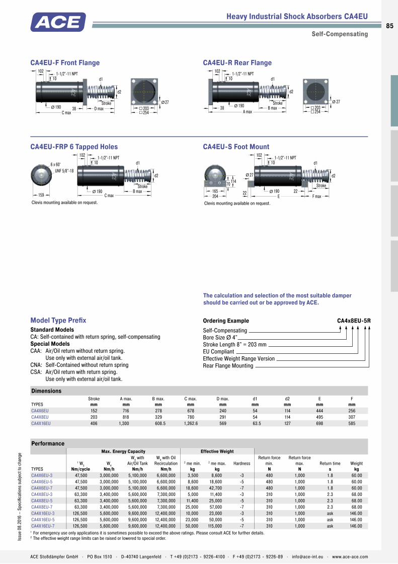
The calculation and selection of the most suitable damper should be carried out or be approved by ACE.
PerformanceMax. Energy Capacity Effective Weight
TYPES
1 W3Nm/cycle
W4Nm/h
W4 with Air/Oil Tank
Nm/h
W4 with Oil Recirculation
Nm/h2 me min.
kg2 me max.
kgHardness
Return force min.
N
Return force max.
NReturn time
sWeight
kgCA4X6EU-3 47,500 3,000,000 5,100,000 6,600,000 3,500 8,600 -3 480 1,000 1.8 60.00CA4X6EU-5 47,500 3,000,000 5,100,000 6,600,000 8,600 18,600 -5 480 1,000 1.8 60.00CA4X6EU-7 47,500 3,000,000 5,100,000 6,600,000 18,600 42,700 -7 480 1,000 1.8 60.00CA4X8EU-3 63,300 3,400,000 5,600,000 7,300,000 5,000 11,400 -3 310 1,000 2.3 68.00CA4X8EU-5 63,300 3,400,000 5,600,000 7,300,000 11,400 25,000 -5 310 1,000 2.3 68.00CA4X8EU-7 63,300 3,400,000 5,600,000 7,300,000 25,000 57,000 -7 310 1,000 2.3 68.00CA4X16EU-3 126,500 5,600,000 9,600,000 12,400,000 10,000 23,000 -3 310 1,000 ask 146.00CA4X16EU-5 126,500 5,600,000 9,600,000 12,400,000 23,000 50,000 -5 310 1,000 ask 146.00CA4X16EU-7 126,500 5,600,000 9,600,000 12,400,000 50,000 115,000 -7 310 1,000 ask 146.00
1 For emergency use only applications it is sometimes possible to exceed the above ratings. Please consult ACE for further details.2 The effective weight range limits can be raised or lowered to special order.
Dimensions
TYPESStroke
mmA max.
mmB max.
mmC max.
mmD max.
mmd1
mmd2
mmE
mmF
mmCA4X6EU 152 716 278 678 240 54 114 444 256CA4X8EU 203 818 329 780 291 54 114 495 307CA4X16EU 406 1,300 608.5 1,262.6 569 63.5 127 698 585
Ordering Example CA4x8EU-5RSelf-CompensatingBore Size Ø 4"Stroke Length 8" = 203 mmEU CompliantEffective Weight Range VersionRear Flange Mounting
Model Type Prefi xStandard ModelsCA: Self-contained with return spring, self-compensatingSpecial ModelsCAA: Air/Oil return without return spring.
Use only with external air/oil tank. CNA: Self-Contained without return springCSA: Air/Oil return with return spring.
Use only with external air/oil tank.
Heavy Industrial Shock Absorbers CA4EU
Self-Compensating
C maxD max38
254203
27Ø
d2
Stroke
d1
190Ø
1-1/2"-11 NPT102
10
CA4EU-F Front Flange
A max
d1
B max38 190
d2
Ø Stroke
254203
27Ø
1-1/2"-11 NPT102
10
CA4EU-R Rear Flange
6 x 60°
159 C maxB max
1-1/2"-11 NPT102
10
190Ø
d1
d2UNF 5/8"-18
Stroke
CA4EU-FRP 6 Tapped Holes
Clevis mounting available on request.
114
204165
70
27
E2222
F max
Ø
190Ø
d2
d1
Stroke
1-1/2"-11 NPT102
10
CA4EU-S Foot Mount
Clevis mounting available on request.
85Is
sue
08.2
016
– Sp
ecifi
catio
ns s
ubje
ct to
cha
nge
ACE Stoßdämpfer GmbH . PO Box 1510 . D-40740 Langenfeld . T +49 (0)2173 - 9226-4100 . F +49 (0)2173 - 9226-89 . [email protected] . www.ace-ace.com

Piston Rod
Return Spring
Pressure Chamber with Metering Orifices
Rod Button
Seals
Piston
Main Bearing
Outer Body
Piston Ring
Accumulator
Adjustment Chamber
Rear Adjustment Segment
Technical Data
Strong and adjustable: Also in ACE’s range of units ares heavy duty industrial shock absorbers, which can be adjusted. The models from the A1½ to 3 range, which weigh between 7.55 and 35.5 kg, are extremely robust, ready-to-install hydraulic machine elements with impressively high energy absorption levels and a wide range of damping rates.
Their special aspect is the fl exibility,as all the absorbers can be adjusted using a socket on the absorber base and be perfectly adapted to the required data. The A models cover a range of effective loads from 195 to 204,000 kg and can absorb up to 44,000 Nm energy.
These heavy duty, adjustable ACE industrial shock absorbers are the fi rst choice in heavy duty applications and generally in heavy mechanical engineering when the usage data has not been exactly determined.
A1½ to A3Heavy Industrial Shock Absorbers Deceleration of heavy loads and progressive adjustment
Heavy Industrial Shock Absorbers
Adjustable
Energy capacity: 2,350 Nm/Cycle to 44,000 Nm/CycleImpact velocity range: 0.1 m/s to 5 m/s. Other speeds on request.Operating temperature range: -12 °C to +66 °C. Other temperatures on request.Mounting: In any positionPositive stop: External positive stops 2.5 mm to 3 mm before the end of stroke provided by the customer.Adjustment: Hard impact at the start of stroke, adjust the ring towards 9. Hard impact at the end of stroke, adjust the ring towards 0.
Material: Outer body: Steel corrosion-resist-ant coating; Piston rod: Hard chrome plated steel; Rod end button: Hardened steel and corrosion-resistant coating; Return spring: Zinc plated steelDamping medium: Automatic Transmission Fluid (ATF)Application fi eld: Portal systems, Machines and plants, Conveyor systems, Crane systemsNote: For emergency use only applications and for continous use it is possible to exceed the published max. capacity ratings. In this case, please consult ACE.
Safety instructions: External materials in the surrounding area can attack the seal components and lead to a shorter service life. Please contact ACE for appropriate solution suggestions. Do not paint the shock absorbers due to heat emission.On request: Special oils, nickel-plated, increased corrosion protection or other special options are available on request.
86
Issu
e 08
.201
6 –
Spec
ifi ca
tions
sub
ject
to c
hang
e
ACE Stoßdämpfer GmbH . PO Box 1510 . D-40740 Langenfeld . T +49 (0)2173 - 9226-4100 . F +49 (0)2173 - 9226-89 . [email protected] . www.ace-ace.com

Piston Rod
Return Spring
Pressure Chamber with Metering Orifices
Rod Button
Seals
Piston
Main Bearing
Outer Body
Piston Ring
Accumulator
Adjustment Chamber
Rear Adjustment Segment
The calculation and selection of the most suitable damper should be carried out or be approved by ACE.
PerformanceMax. Energy Capacity Effective Weight
TYPES
1 W3Nm/cycle
2 W4Nm/h
2 W4 with Air/Oil Tank
Nm/h3 me min.
kg3 me max.
kg
Return force min.
N
Return force max.
NReturn time
s
Side Load Angle max.
°Weight
kgA1½X2EU 2,350 362,000 452,000 195 32,000 160 210 0.10 5 7.55A1½X3½EU 4,150 633,000 791,000 218 36,000 110 210 0.25 4 8.90A1½X5EU 5,900 904,000 1,130,000 227 41,000 90 230 0.40 3 9.35A1½X6½EU 7,700 1,180,000 1,469,000 308 45,000 90 430 0.40 2 11.95
1 For emergency use only applications it is sometimes possible to exceed the above ratings. Please consult ACE for further details.2 Figures for oil recirculation systems on request.3 The effective weight range limits can be raised or lowered to special order.
Dimensions
TYPESStroke
mmL min.mm
L max.mm
L1mm
L2mm
L3mm
L4mm
A1½X2EU 50 277.8 328.6 195.2 54.2 - -A1½X3½EU 89 316.6 405.6 233 54.2 170 58.6A1½X5EU 127 354.8 481.8 271.5 54.2 208 58.6A1½X6½EU 165 412 577 329 73 246 78
Ordering Example A1½x2EURAdjustableBore Size Ø 1½"Stroke Length 2" = 50.8 mmEU CompliantRear Flange Mounting
Model Type Prefi xStandard ModelsA: Self-contained with return spring, adjustableSpecial ModelsAA: Air/Oil return without return spring.
Use only with external air/oil tank. NA: Self-contained without return springSA: Air/Oil return with return spring.
Use only with external air/oil tank.
Heavy Industrial Shock Absorbers A1½EU
Adjustable
L219
Stroke102
76
13.6Ø
Ø 25.4
69
A1½EU-F Front Flange
L1
19 Stroke102
76
13.6Ø
Ø 25.4
69
A1½EU-R Rear Flange
31.8
19.119
19.1
16
15.9 38
Lminmax
ØØStroke
Ø 25.4
A1½EU-C Clevis Mount
L416 StrokeL3
140
5113
165
18
102
Ø
Ø 25.4
69
A1½EU-S Foot Mount
87Is
sue
08.2
016
– Sp
ecifi
catio
ns s
ubje
ct to
cha
nge
ACE Stoßdämpfer GmbH . PO Box 1510 . D-40740 Langenfeld . T +49 (0)2173 - 9226-4100 . F +49 (0)2173 - 9226-89 . [email protected] . www.ace-ace.com

The calculation and selection of the most suitable damper should be carried out or be approved by ACE.
PerformanceMax. Energy Capacity Effective Weight
TYPES
1 W3Nm/cycle
2 W4Nm/h
2 W4 with Air/Oil Tank
Nm/h3 me min.
kg3 me max.
kg
Return force min.
N
Return force max.
NReturn time
s
Side Load Angle max.
°Weight
kgA2X2EU 3,600 1,100,000 1,350,000 250 77,000 210 285 0.25 3 13.50A2X4EU 9,000 1,350,000 1,700,000 250 82,000 150 285 0.50 3 19.85A2X6EU 13,500 1,600,000 2,000,000 260 86,000 150 400 0.60 3 19.30A2X8EU 19,200 1,900,000 2,400,000 260 90,000 230 650 0.70 3 19.85A2X10EU 23,700 2,200,000 2,700,000 320 113,000 160 460 0.80 3 19.85
1 For emergency use only applications it is sometimes possible to exceed the above ratings. Please consult ACE for further details.2 Figures for oil recirculation systems on request.3 The effective weight range limits can be raised or lowered to special order.
Dimensions
TYPESStroke
mmA max.
mmB max.
mmC
mmD max.
mmE
mmA2X2EU 50 313 110 173 125 70A2X4EU 102 414 160 224 175 70A2X6EU 152 516 211 275 226 70A2X8EU 203 643 287 326 302 92A2X10EU 254 745 338 377 353 108
Ordering Example A2x6EU-RAdjustableBore Size Ø 2"Stroke Length 6" = 152 mmEU CompliantRear Flange Mounting
Model Type Prefi xStandard ModelsA: Self-contained with return spring, adjustableSpecial ModelsAA: Air/Oil return without return spring.
Use only with external air/oil tank. NA: Self-contained without return springSA: Air/Oil return with return spring.
Use only with external air/oil tank.
Heavy Industrial Shock Absorbers A2EU
Adjustable
A max19 19 B max
Ø 118
M100x2
140
17
111
ØØ 35
E
Stroke
A2EU-F Front Flange
A max
19Stroke
19 B max
Ø 35
E
Ø 118
M100x2
140
17
111
Ø
A2EU-R Rear Flange
C32 15
D max15
60
6036
160190
Ø18
Ø 35
E
Ø 118 Stroke
A2EU-SM Foot Mount
88
Issu
e 08
.201
6 –
Spec
ifi ca
tions
sub
ject
to c
hang
e
ACE Stoßdämpfer GmbH . PO Box 1510 . D-40740 Langenfeld . T +49 (0)2173 - 9226-4100 . F +49 (0)2173 - 9226-89 . [email protected] . www.ace-ace.com

The calculation and selection of the most suitable damper should be carried out or be approved by ACE.
PerformanceMax. Energy Capacity Effective Weight
TYPES
1 W3Nm/cycle
2 W4Nm/h
2 W4 with Air/Oil Tank
Nm/h3 me min.
kg3 me max.
kg
Return force min.
N
Return force max.
NReturn time
s
Side Load Angle max.
°Weight
kgA3X5EU 15,800 2,260,000 2,800,000 480 154,000 270 710 0.6 3 35.50A3X8EU 28,200 3,600,000 4,520,000 540 181,500 280 740 0.8 3 46.20A3X12EU 44,000 5,400,000 6,780,000 610 204,000 270 730 1.2 3 48.00
1 For emergency use only applications it is sometimes possible to exceed the above ratings. Please consult ACE for further details.2 Figures for oil recirculation systems on request.3 The effective weight range limits can be raised or lowered to special order.
Dimensions
TYPESStroke
mmA max.
mmB max.
mmC
mmD max.
mmA3X5EU 127 490.5 211 254 224A3X8EU 203 641 286 330 300A3X12EU 305 890 434 432 447
Ordering Example A3x8EURAdjustableBore Size Ø 3"Stroke Length 8" = 203 mmEU CompliantRear Flange Mounting
Model Type Prefi xStandard ModelsA: Self-contained with return spring, adjustableSpecial ModelsAA: Air/Oil return without return spring.
Use only with external air/oil tank. NA: Self-contained without return springSA: Air/Oil return with return spring.
Use only with external air/oil tank.
Heavy Industrial Shock Absorbers A3EU
Adjustable
A max25 25 B max
Ø 155
M130x2
165
17
136.5
Ø
124152
112
Ø 44.5
Stroke
A3EU-F Front Flange
A max
25Stroke
25 B max
Ø 44.5
112M130x2
Ø 155
165
17
136.5
Ø
124152
A3EU-R Rear Flange
C45 19
D max23
80
8044
216254
Ø17
Ø 44.5
112
Ø 155 Stroke
A3EU-S Foot Mount
89Is
sue
08.2
016
– Sp
ecifi
catio
ns s
ubje
ct to
cha
nge
ACE Stoßdämpfer GmbH . PO Box 1510 . D-40740 Langenfeld . T +49 (0)2173 - 9226-4100 . F +49 (0)2173 - 9226-89 . [email protected] . www.ace-ace.com

9090
ACE Stoßdämpfer GmbH . PO Box 1510 . D-40740 Langenfeld . T +49 (0)2173 - 9226-4100 . [email protected] . www.ace-ace.com
Issu
e 08
.201
6 –
Spec
ifica
tions
sub
ject
to c
hang
e
138
8.5Ø
22
43
2.5
NPT 1/8"
102
Ø
NPT 1/8"
10.4
89
159
Ø
195
38
16.8
141
279
Ø
330
50.8
NPT 3/4-14"
NPT 3/4-14"
NPT 3/4-14"
Operating pressure: Max. 8 barOperating temperature range: 80 °CDamping medium: ATF-Oil 42 cSt at 40 °C Mount air/oil tank higher than shock absorber. Bleed all air from system before operating.
Technical Data
Industrial Shock Absorbers / Heavy Industrial Shock Absorbers
Shock absorbers convert the introduced energy into heat. The more frequent-ly a shock absorber is stressed per hour, the hotter the oil volume becomes over time. If the requirements placed on the impact frequency of a shock absorber are especially high the use of an air-oil tank is just the right thing.
Thanks to the increased oil volume and the resulting heat dissipation, the upper limit of the possible hourly energy capacity of the shock absorber increases significantly.
Another characteristic of the air-oil tank is the opportunity for controlled piston return if no permanent return force through an integrated spring in the shock absorber is desired.
Air/Oil Tanks AO
AO1
Oil capacity 20 cm3
Material: Aluminium caps
AO3
Oil capacity 370 cm3
Material: Steel
AO6
Oil capacity 2,600 cm3
Material: Steel
Detail drawings on request
Safety instructions: Exhaust tank before carrying out service. Check valve holds pressure!Suggested air/oil tanks in accordance with W4 ratings
Air/Oil Tanksfor industrial shock absorbers For high cycle rates and extreme temperatures with limited mounting space
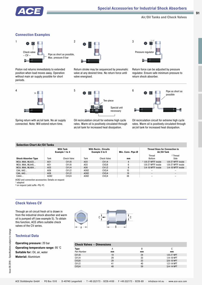
91Is
sue
08.2
016
– Sp
ecifi
catio
ns s
ubje
ct to
cha
nge
ACE Stoßdämpfer GmbH . PO Box 1510 . D-40740 Langenfeld . T +49 (0)2173 - 9226-4100 . F +49 (0)2173 - 9226-89 . [email protected] . www.ace-ace.com
Check valve – CV – Pipe as short as possible,
Max. pressure 8 bar
Pressure regulator
Pipe as short as possible
Tee-piece
Special unit necessary
A B
CC
Piston rod returns immediately to extended position when load moves away. Operation without main air supply possible for short periods.
Return stroke may be sequenced by pneumatic valve at any desired time. No return force until valve energised.
Return force can be adjusted by pressure regulator. Ensure safe minimum pressure to return shock absorber.
Connection Examples
Special Accessories for Industrial Shock Absorbers
Air/Oil Tanks and Check Valves
Spring return with air/oil tank. No air supply connected. Note: Will extend return time.
Oil recirculation circuit for extreme high cycle rates. Warm oil is positively circulated through air/oil tank for increased heat dissipation.
Oil recirculation circuit for extreme high cycle rates. Warm oil is positively circulated through air/oil tank for increased heat dissipation.
Operating pressure: 20 barOperating temperature range: 95 °C Suitable for: Oil, air, waterMaterial: Aluminium
Check Valves CV
Through an oil circuit fresh oil is drawn in from the industrial shock absorber and warm oil is pumped off (see example 5). To obtain this function, ACE offers suitable check valves of the CV series.
1 2 3
4 5 6
Selection Chart Air/Oil TanksWith Tank
Example 1 to 4With Recirc. Circuits
Example 5 to 6 Min. Conn. Pipe ØThread Sizes for Connection to
Air/Oil Tank
Shock Absorber Type Tank Check Valve Tank Check Valve mmThreadBottom
2 Thread Side
MCA, MAA, MLA33... AO1 CV1/8 AO3 CV1/4 4 1 1/8-27 NPTF inside 1/8-27 NPTF insideMCA, MAA, MLA45... AO1 CV1/8 AO3 CV3/8 6 1/8-27 NPTF inside 1/8-27 NPTF insideMCA, MAA, MLA64... AO3 CV1/4 AO6 CV1/2 8 1/4-18 NPTF inside 1/4-18 NPTF insideCAA, AA2... AO6 CV1/2 AO82 CV3/4 15 – –CAA, AA3... AO6 CV1/2 AO82 CV3/4 19 – –CAA4... AO82 CV3/4 AO82 CV3/4 38 – –
AO82 and connection accessories: Details on request 1 adapted 2 on request (add suffix -PG/-P)
Check Valves – Dimensions Type Part Number
A mm
B mm
C mm
CV1/8 19 24 1/8-27 NPTCV1/4 29 33 1/4-18 NPTCV3/8 29 33 3/8-18 NPTCV1/2 41 40 1/2-14 NPTCV3/4 48 59 3/4-14 NPT
Technical Data

9292
ACE Stoßdämpfer GmbH . PO Box 1510 . D-40740 Langenfeld . T +49 (0)2173 - 9226-4100 . [email protected] . www.ace-ace.comACE Stoßdämpfer GmbH . PO Box 1510 . D-40740 Langenfeld . T +49 (0)2173 - 9226-4100 . [email protected] . www.ace-ace.com
The exceedingly successful TUBUS series from ACE is a perfect alter-native, when masses don't need to be decelerated to an exact point. Available in more than 140 different versions, the profi le dampers are used to slow down masses, particularly under extreme conditions.
They are also recommended for use if there is little installation space available. Manufactured in co-polyester elastomer, the highly resistant absorbers provide the best benefi ts in areas where other materials fail or where a similarly high service life of up to 1 million load changes cannot be achieved. They are affordable, compact and light and absorb the energy with different damping characteristics depending on the design.
Profi le DampersThe low cost alternative for continuous duty
Automation Control
Very good price/performance ratio
Reliable in extreme situations
Highly resistant material
Compact and lightweight design
Easy to mount
Long service life
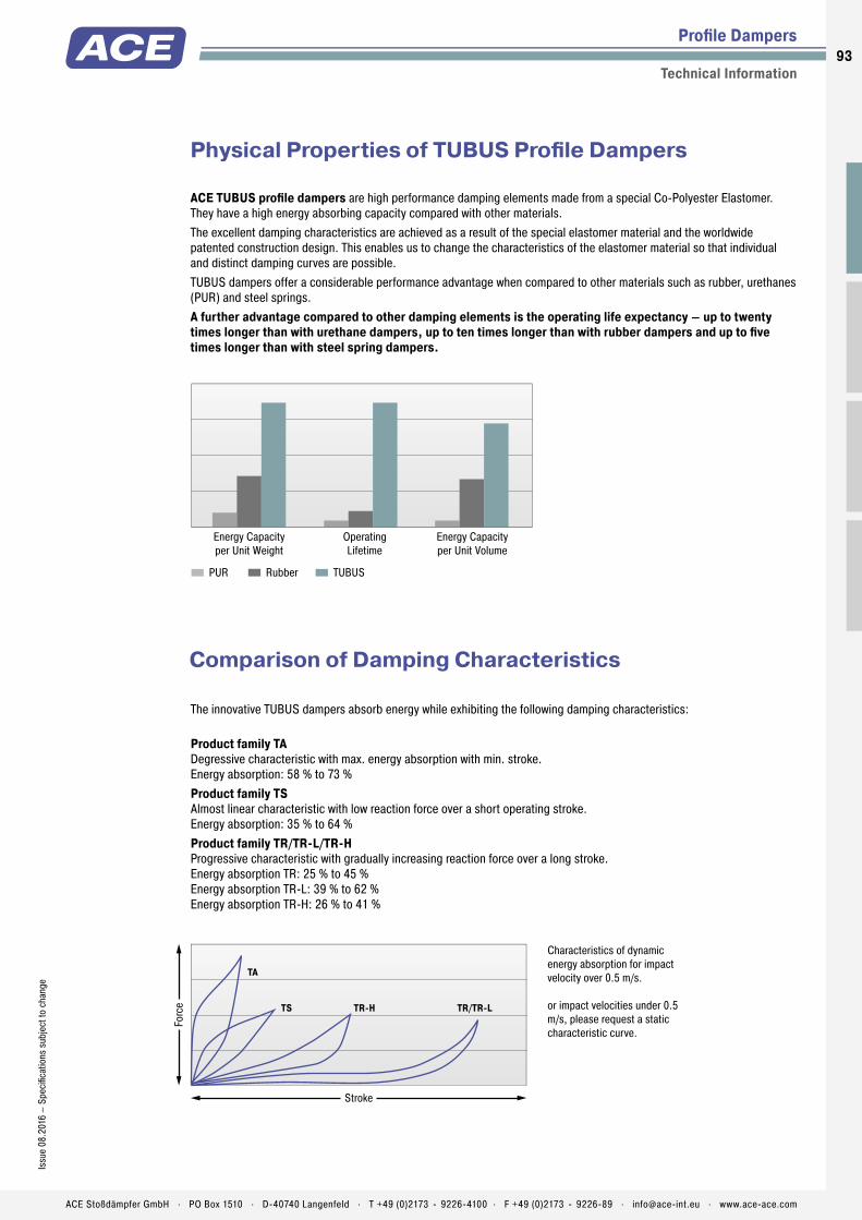
93Is
sue
08.2
016
– Sp
ecifi
catio
ns s
ubje
ct to
cha
nge
ACE Stoßdämpfer GmbH . PO Box 1510 . D-40740 Langenfeld . T +49 (0)2173 - 9226-4100 . F +49 (0)2173 - 9226-89 . [email protected] . www.ace-ace.com
TUBUSRubberPUR
Energy Capacity per Unit Weight
OperatingLifetime
Energy Capacity per Unit Volume
Stroke
Forc
e
TA
TS TR-H TR/TR-L
ACE TUBUS profile dampers are high performance damping elements made from a special Co-Polyester Elastomer. They have a high energy absorbing capacity compared with other materials.The excellent damping characteristics are achieved as a result of the special elastomer material and the worldwide patented construction design. This enables us to change the characteristics of the elastomer material so that individual and distinct damping curves are possible.TUBUS dampers offer a considerable performance advantage when compared to other materials such as rubber, urethanes (PUR) and steel springs.A further advantage compared to other damping elements is the operating life expectancy – up to twenty times longer than with urethane dampers, up to ten times longer than with rubber dampers and up to five times longer than with steel spring dampers.
The innovative TUBUS dampers absorb energy while exhibiting the following damping characteristics:
Product family TA Degressive characteristic with max. energy absorption with min. stroke. Energy absorption: 58 % to 73 %Product family TS Almost linear characteristic with low reaction force over a short operating stroke. Energy absorption: 35 % to 64 %Product family TR/TR-L/TR-H Progressive characteristic with gradually increasing reaction force over a long stroke. Energy absorption TR: 25 % to 45 % Energy absorption TR-L: 39 % to 62 % Energy absorption TR-H: 26 % to 41 %
Characteristics of dynamic energy absorption for impact velocity over 0.5 m/s. or impact velocities under 0.5 m/s, please request a static characteristic curve.
Comparison of Damping Characteristics
Physical Properties of TUBUS Profile Dampers
Profile Dampers
Technical Information
Reliable in extreme situations
Easy to mount
Long service life
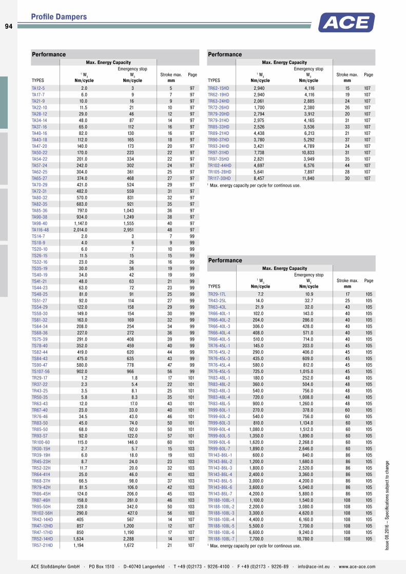
Profile Dampers
PerformanceMax. Energy Capacity
TYPES
1 W3Nm/cycle
Emergency stopW3
Nm/cycleStroke max.
mmPage
TA12-5 2.0 3 5 97TA17-7 6.0 9 7 97TA21-9 10.0 16 9 97TA22-10 11.5 21 10 97TA28-12 29.0 46 12 97TA34-14 48.0 87 14 97TA37-16 65.0 112 16 97TA40-16 82.0 130 16 97TA43-18 112.0 165 18 97TA47-20 140.0 173 20 97TA50-22 170.0 223 22 97TA54-22 201.0 334 22 97TA57-24 242.0 302 24 97TA62-25 304.0 361 25 97TA65-27 374.0 468 27 97TA70-29 421.0 524 29 97TA72-31 482.0 559 31 97TA80-32 570.0 831 32 97TA82-35 683.0 921 35 97TA85-36 797.0 1,043 36 97TA90-38 934.0 1,249 38 97TA98-40 1,147.0 1,555 40 97TA116-48 2,014.0 2,951 48 97TS14-7 2.0 3 7 99TS18-9 4.0 6 9 99TS20-10 6.0 7 10 99TS26-15 11.5 15 15 99TS32-16 23.0 26 16 99TS35-19 30.0 36 19 99TS40-19 34.0 42 19 99TS41-21 48.0 63 21 99TS44-23 63.0 72 23 99TS48-25 81.0 91 25 99TS51-27 92.0 114 27 99TS54-29 122.0 158 29 99TS58-30 149.0 154 30 99TS61-32 163.0 169 32 99TS64-34 208.0 254 34 99TS68-36 227.0 272 36 99TS75-39 291.0 408 39 99TS78-40 352.0 459 40 99TS82-44 419.0 620 44 99TS84-43 475.0 635 43 99TS90-47 580.0 778 47 99TS107-56 902.0 966 56 99TR29-17 1.2 1.8 17 101TR37-22 2.3 5.4 22 101TR43-25 3.5 8.1 25 101TR50-35 5.8 8.3 35 101TR63-43 12.0 17.0 43 101TR67-40 23.0 33.0 40 101TR76-46 34.5 43.0 46 101TR83-50 45.0 74.0 50 101TR85-50 68.0 92.0 50 101TR93-57 92.0 122.0 57 101TR100-60 115.0 146.0 60 101TR30-15H 2.7 5.7 15 103TR39-19H 6.0 18.0 19 103TR45-23H 8.7 24.0 23 103TR52-32H 11.7 20.0 32 103TR64-41H 25.0 46.0 41 103TR68-37H 66.5 98.0 37 103TR79-42H 81.5 106.0 42 103TR86-45H 124.0 206.0 45 103TR87-46H 158.0 261.0 46 103TR95-50H 228.0 342.0 50 103TR102-56H 290.0 427.0 56 103TR42-14HD 405 567 14 107TR47-12HD 857 1,200 12 107TR47-17HD 850 1,190 17 107TR52-14HD 1,634 2,288 14 107TR57-21HD 1,194 1,672 21 107
PerformanceMax. Energy Capacity
TYPES
1 W3Nm/cycle
Emergency stopW3
Nm/cycleStroke max.
mmPage
TR62-15HD 2,940 4,116 15 107TR62-19HD 2,940 4,116 19 107TR63-24HD 2,061 2,885 24 107TR72-26HD 1,700 2,380 26 107TR79-20HD 2,794 3,912 20 107TR79-31HD 2,975 4,165 31 107TR85-33HD 2,526 3,536 33 107TR89-21HD 4,438 6,213 21 107TR90-37HD 3,780 5,292 37 107TR93-24HD 3,421 4,789 24 107TR97-31HD 7,738 10,833 31 107TR97-35HD 2,821 3,949 35 107TR102-44HD 4,697 6,576 44 107TR105-28HD 5,641 7,897 28 107TR117-30HD 8,457 11,840 30 107
1 Max. energy capacity per cycle for continous use.
PerformanceMax. Energy Capacity
TYPES
1 W3Nm/cycle
Emergency stopW3
Nm/cycleStroke max.
mmPage
TR29-17L 7.2 10.9 17 105TR43-25L 14.0 32.7 25 105TR63-43L 21.9 32.0 43 105TR66-40L-1 102.0 143.0 40 105TR66-40L-2 204.0 286.0 40 105TR66-40L-3 306.0 428.0 40 105TR66-40L-4 408.0 571.0 40 105TR66-40L-5 510.0 714.0 40 105TR76-45L-1 145.0 203.0 45 105TR76-45L-2 290.0 406.0 45 105TR76-45L-3 435.0 609.0 45 105TR76-45L-4 580.0 812.0 45 105TR76-45L-5 725.0 1,015.0 45 105TR83-48L-1 180.0 252.0 48 105TR83-48L-2 360.0 504.0 48 105TR83-48L-3 540.0 756.0 48 105TR83-48L-4 720.0 1,008.0 48 105TR83-48L-5 900.0 1,260.0 48 105TR99-60L-1 270.0 378.0 60 105TR99-60L-2 540.0 756.0 60 105TR99-60L-3 810.0 1,134.0 60 105TR99-60L-4 1,080.0 1,512.0 60 105TR99-60L-5 1,350.0 1,890.0 60 105TR99-60L-6 1,620.0 2,268.0 60 105TR99-60L-7 1,890.0 2,646.0 60 105TR143-86L-1 600.0 840.0 86 105TR143-86L-2 1,200.0 1,680.0 86 105TR143-86L-3 1,800.0 2,520.0 86 105TR143-86L-4 2,400.0 3,360.0 86 105TR143-86L-5 3,000.0 4,200.0 86 105TR143-86L-6 3,600.0 5,040.0 86 105TR143-86L-7 4,200.0 5,880.0 86 105TR188-108L-1 1,100.0 1,540.0 108 105TR188-108L-2 2,200.0 3,080.0 108 105TR188-108L-3 3,300.0 4,620.0 108 105TR188-108L-4 4,400.0 6,160.0 108 105TR188-108L-5 5,500.0 7,700.0 108 105TR188-108L-6 6,600.0 9,240.0 108 105TR188-108L-7 7,700.0 10,780.0 108 105
1 Max. energy capacity per cycle for continous use.
94
Issu
e 08
.201
6 –
Spec
ifica
tions
sub
ject
to c
hang
e
ACE Stoßdämpfer GmbH . PO Box 1510 . D-40740 Langenfeld . T +49 (0)2173 - 9226-4100 . F +49 (0)2173 - 9226-89 . [email protected] . www.ace-ace.com

Product Families
Overview
Profi le Dampers
TUBUS TA Axial Damping Compact size and strong force absorptionLinear slides, Pneumatic cylinders, Handling modules, Machines and plants
Page 96
TUBUS TS Axial Soft Damping Compact size and smooth decelerationLinear slides, Pneumatic cylinders, Handling modules, Machines and plants
Page 98
TUBUS TR Radial Damping Compact size and soft decelerationFurniture industry, Sports equipment, Linear slides, Pneumatic cylinders
Page 100
TUBUS TR-H Radial Damping, Hard Version Compact size with soft deceleration and high energy absorptionFurniture industry, Sports equipment, Linear slides, Pneumatic cylinders
Page 102
TUBUS TR-L Radial Damping, Long Version Powerhouse in long body lengthOffshore industry, Agricultural machinery, Impact panels, Conveyor systems
Page 104
TUBUS TR-HD Radial Damping, Heavy Duty Version Compact powerhouse in solid materialOffshore industry, Agricultural machinery, Impact panels, Conveyor systems
Page 106
95Is
sue
08.2
016
– Sp
ecifi
catio
ns s
ubje
ct to
cha
nge
ACE Stoßdämpfer GmbH . PO Box 1510 . D-40740 Langenfeld . T +49 (0)2173 - 9226-4100 . F +49 (0)2173 - 9226-89 . [email protected] . www.ace-ace.com

Profile Body
Mounting Screw
Technical Data
Very effi cient energy guzzlers: The TA profi le dampers from the ACE TUBUS-Series are maintenance-free and ready to install. They consist of co-polyester elastomer; a material that only heats up slightly and ensures consistent damping. The TA models absorb a lot of energy at the start of the stroke.
The TA family has been specially developed for maximum energy absorption within a range of 2 Nm to 2,951 Nm. The minimum height is thanks to the space-saving shape with Ø 12 mm to Ø 116 mm. The dampers can be very easily and quickly fi xed with the provided special screw.
These compact, cost-effective machine elements are ideal as end position dampers in linear axes, in toolmaking and tool machines, in hydraulic and pneumatic equipment, handling equipment and other applications.
TUBUS TAProfi le Dampers Compact size and strong force absorption
Profi le Dampers
Axial Damping
Energy capacity: 2 Nm/Cycle to 2,951 Nm/CycleEnergy absorption: 58 % to 73 %Dynamic force range: 870 N to 90,000 NOperating temperature range: -40 °C to +90 °CConstruction size: 12 mm to 116 mmMounting: In any positionMaterial hardness rating: Shore 55DMaterial: Profi le body: Co-Polyester ElastomerEnvironment: Resistant to microbes, seawater or chemical attack. Excellent UV
and ozone resistance. Material does not absorb water or swell.Impact velocity range: Max. 5 m/sTorque max.: M3: 1 Nm M4: 1.7 Nm M5: 2.3 Nm M6: 6 Nm M8: 20 Nm M12: 50 Nm M16: 120 NmApplication fi eld: Linear slides, Pneumatic cylinders, Handling modules, Machines and plants
Note: Suitable for emergency stop applica-tions and for continous use. For applications with preloading and increased temperatures please consult ACE.Safety instructions: Mounting screw should additionally be secured with Loctite.On request: Special strokes, -characteristics, -spring rates, -sizes and -materials.
96
Issu
e 08
.201
6 –
Spec
ifi ca
tions
sub
ject
to c
hang
e
ACE Stoßdämpfer GmbH . PO Box 1510 . D-40740 Langenfeld . T +49 (0)2173 - 9226-4100 . F +49 (0)2173 - 9226-89 . [email protected] . www.ace-ace.com
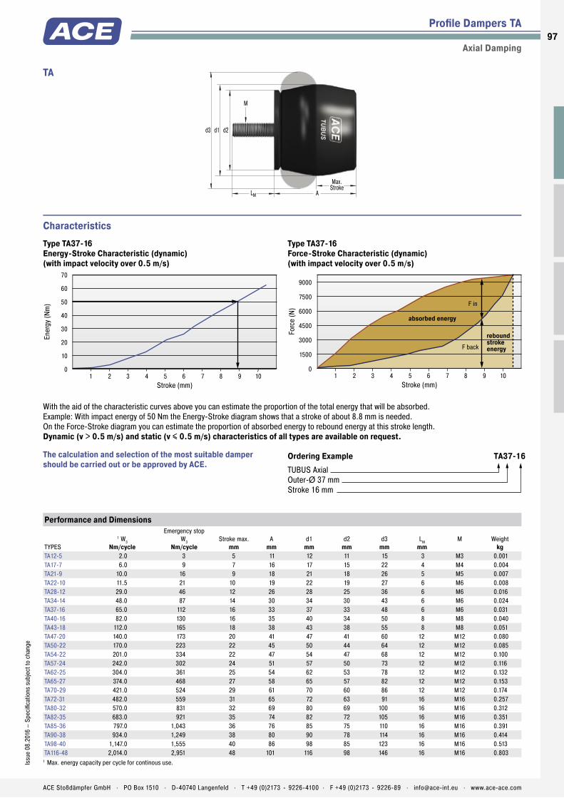
Profile Body
Mounting Screw
Profi le Dampers TA
Axial Damping
Stroke (mm)
Ener
gy (N
m)
70
60
50
40
30
20
10
0 1 2 3 4 5 6 7 8 9 10
9000
7500
6000
4500
3000
1500
0
Stroke (mm)
Forc
e (N
)
1 2 3 4 5 6 7 8 9 10
absorbed energy
rebound stroke energyF back
F in
Characteristics
Ordering Example TA37-16TUBUS AxialOuter-Ø 37 mmStroke 16 mm
The calculation and selection of the most suitable damper should be carried out or be approved by ACE.
With the aid of the characteristic curves above you can estimate the proportion of the total energy that will be absorbed.Example: With impact energy of 50 Nm the Energy-Stroke diagram shows that a stroke of about 8.8 mm is needed.On the Force-Stroke diagram you can estimate the proportion of absorbed energy to rebound energy at this stroke length.Dynamic (v > 0.5 m/s) and static (v ≤ 0.5 m/s) characteristics of all types are available on request.
Type TA37-16Energy-Stroke Characteristic (dynamic)(with impact velocity over 0.5 m/s)
Type TA37-16Force-Stroke Characteristic (dynamic)(with impact velocity over 0.5 m/s)
Performance and Dimensions
TYPES
1 W3Nm/cycle
Emergency stopW3
Nm/cycleStroke max.
mmA
mmd1
mmd2
mmd3
mmLM
mmM Weight
kgTA12-5 2.0 3 5 11 12 11 15 3 M3 0.001TA17-7 6.0 9 7 16 17 15 22 4 M4 0.004TA21-9 10.0 16 9 18 21 18 26 5 M5 0.007TA22-10 11.5 21 10 19 22 19 27 6 M6 0.008TA28-12 29.0 46 12 26 28 25 36 6 M6 0.016TA34-14 48.0 87 14 30 34 30 43 6 M6 0.024TA37-16 65.0 112 16 33 37 33 48 6 M6 0.031TA40-16 82.0 130 16 35 40 34 50 8 M8 0.040TA43-18 112.0 165 18 38 43 38 55 8 M8 0.051TA47-20 140.0 173 20 41 47 41 60 12 M12 0.080TA50-22 170.0 223 22 45 50 44 64 12 M12 0.085TA54-22 201.0 334 22 47 54 47 68 12 M12 0.100TA57-24 242.0 302 24 51 57 50 73 12 M12 0.116TA62-25 304.0 361 25 54 62 53 78 12 M12 0.132TA65-27 374.0 468 27 58 65 57 82 12 M12 0.153TA70-29 421.0 524 29 61 70 60 86 12 M12 0.174TA72-31 482.0 559 31 65 72 63 91 16 M16 0.257TA80-32 570.0 831 32 69 80 69 100 16 M16 0.312TA82-35 683.0 921 35 74 82 72 105 16 M16 0.351TA85-36 797.0 1,043 36 76 85 75 110 16 M16 0.391TA90-38 934.0 1,249 38 80 90 78 114 16 M16 0.414TA98-40 1,147.0 1,555 40 86 98 85 123 16 M16 0.513TA116-48 2,014.0 2,951 48 101 116 98 146 16 M16 0.803
1 Max. energy capacity per cycle for continous use.
d3 d2d1
LM A
Max.Stroke
M
TA
97Is
sue
08.2
016
– Sp
ecifi
catio
ns s
ubje
ct to
cha
nge
ACE Stoßdämpfer GmbH . PO Box 1510 . D-40740 Langenfeld . T +49 (0)2173 - 9226-4100 . F +49 (0)2173 - 9226-89 . [email protected] . www.ace-ace.com

Profile Body
Mounting Screw
Technical Data
Energy absorption in a compact and uniform way: The TS (TUBUS soft) profi le dampers are also manufactured from co-polyester elastomer. Due to the almost linear damping characteristic curve, the maintenance-free, ready-to-install components softly absorb the energy with minimum strain on the machine. Consistent damping is helped by the low temperature increase of the material during operation.
The TS-Series impresses with maximum energy absorption within a range of 2 Nm to 966 Nm within a minimum height. The space-saving design has been implemented from Ø 14 mm to Ø 107 mm. The special screw supplied is used to simply and quickly fi x the profi le dampers in place.
Suitable for emergency stop and permanent applications, the cost-effective, durable TUBUS TS can be used as end position dampers in linear axes, in toolmaking and tool machines and in hydraulic, pneumatic and handling equipment.
TUBUS TSProfi le Dampers Compact size and smooth deceleration
Profi le Dampers
Axial Soft Damping
Energy capacity: 2 Nm/Cycle to 966 Nm/CycleEnergy absorption: 35 % to 64 %Dynamic force range: 533 N to 23,500 NOperating temperature range: -40 °C to +90 °CConstruction size: 14 mm to 107 mmMounting: In any positionMaterial hardness rating: Shore 40DMaterial: Profi le body: Co-Polyester ElastomerEnvironment: Resistant to microbes, seawater or chemical attack. Excellent UV
and ozone resistance. Material does not absorb water or swell.Impact velocity range: Max. 5 m/sTorque max.: M4: 1.7 Nm M5: 2.3 Nm M6: 6 Nm M12: 50 Nm M16: 120 NmApplication fi eld: Linear slides, Pneumatic cylinders, Handling modules, Machines and plantsNote: Suitable for emergency stop applica-tions and for continous use. For applications
with preloading and increased temperatures please consult ACE.Safety instructions: Mounting screw should additionally be secured with Loctite.On request: Special strokes, -characteristics, -spring rates, -sizes and -materials.
98
Issu
e 08
.201
6 –
Spec
ifi ca
tions
sub
ject
to c
hang
e
ACE Stoßdämpfer GmbH . PO Box 1510 . D-40740 Langenfeld . T +49 (0)2173 - 9226-4100 . F +49 (0)2173 - 9226-89 . [email protected] . www.ace-ace.com

Profile Body
Mounting Screw
Profi le Dampers TS
Axial Soft Damping
Stroke (mm)
Ener
gy (N
m)
70
60
50
40
30
20
10
0 3 6 9 12 15 18
Stroke (mm)
Forc
e (N
)
6000
5000
4000
3000
2000
1000
0 3 6 9 12 15 18
absorbed energy
rebound stroke energy
F back
F in
Characteristics
Ordering Example TS44-23TUBUS Axial SoftOuter-Ø 44 mmStroke 23 mm
The calculation and selection of the most suitable damper should be carried out or be approved by ACE.
With the aid of the characteristic curves above you can estimate the proportion of the total energy that will be absorbed.Example: With impact energy of 50 Nm the Energy-Stroke diagram shows that a stroke of about 14 mm is needed.On the Force-Stroke diagram you can estimate the proportion of absorbed energy to rebound energy at this stroke length.Dynamic (v > 0.5 m/s) and static (v ≤ 0.5 m/s) characteristics of all types are available on request.
Type TS44-23Energy-Stroke Characteristic (dynamic)(with impact velocity over 0.5 m/s)
Type TS44-23Force-Stroke Characteristic (dynamic)(with impact velocity over 0.5 m/s)
Performance and Dimensions
TYPES
1 W3Nm/cycle
Emergency stopW3
Nm/cycleStroke max.
mmA
mmd1
mmd2
mmd3
mmLM
mmM Weight
kgTS14-7 2.0 3 7 15 14 13 19 4 M4 0.003TS18-9 4.0 6 9 18 18 16 24 5 M5 0.006TS20-10 6.0 7 10 21 20 19 27 6 M6 0.008TS26-15 11.5 15 15 28 26 25 37 6 M6 0.015TS32-16 23.0 26 16 32 32 30 44 6 M6 0.021TS35-19 30.0 36 19 36 35 33 48 6 M6 0.028TS40-19 34.0 42 19 38 40 34 51 6 M6 0.031TS41-21 48.0 63 21 41 41 38 55 12 M12 0.051TS44-23 63.0 72 23 45 44 40 60 12 M12 0.072TS48-25 81.0 91 25 49 48 44 64 12 M12 0.086TS51-27 92.0 114 27 52 51 47 69 12 M12 0.102TS54-29 122.0 158 29 55 54 50 73 12 M12 0.116TS58-30 149.0 154 30 59 58 53 78 12 M12 0.132TS61-32 163.0 169 32 62 61 56 83 16 M16 0.203TS64-34 208.0 254 34 66 64 60 87 16 M16 0.233TS68-36 227.0 272 36 69 68 63 92 16 M16 0.248TS75-39 291.0 408 39 75 75 69 101 16 M16 0.301TS78-40 352.0 459 40 79 78 72 105 16 M16 0.339TS82-44 419.0 620 44 84 82 75 110 16 M16 0.346TS84-43 475.0 635 43 85 84 78 115 16 M16 0.402TS90-47 580.0 778 47 92 90 84 124 16 M16 0.490TS107-56 902.0 966 56 110 107 100 147 16 M16 0.733
1 Max. energy capacity per cycle for continous use.
d3 d2d1
LM A
Max.Stroke
M
TS
99Is
sue
08.2
016
– Sp
ecifi
catio
ns s
ubje
ct to
cha
nge
ACE Stoßdämpfer GmbH . PO Box 1510 . D-40740 Langenfeld . T +49 (0)2173 - 9226-4100 . F +49 (0)2173 - 9226-89 . [email protected] . www.ace-ace.com
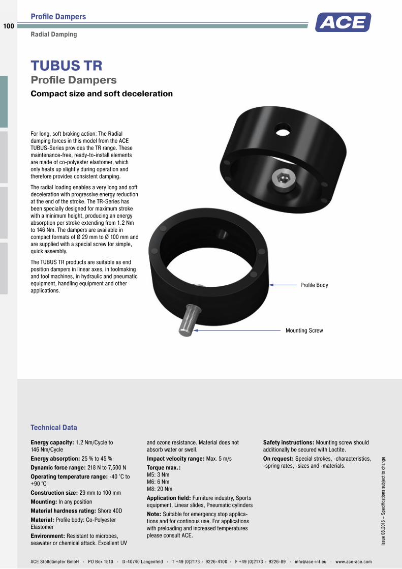
Profile Body
Mounting Screw
Technical Data
For long, soft braking action: The Radial damping forces in this model from the ACE TUBUS-Series provides the TR range. These maintenance-free, ready-to-install elements are made of co-polyester elastomer, which only heats up slightly during operation and therefore provides consistent damping.
The radial loading enables a very long and soft deceleration with progressive energy reduction at the end of the stroke. The TR-Series has been specially designed for maximum stroke with a minimum height, producing an energy absorption per stroke extending from 1.2 Nm to 146 Nm. The dampers are available in compact formats of Ø 29 mm to Ø 100 mm and are supplied with a special screw for simple, quick assembly.
The TUBUS TR products are suitable as end position dampers in linear axes, in toolmaking and tool machines, in hydraulic and pneumatic equipment, handling equipment and other applications.
TUBUS TRProfi le Dampers Compact size and soft deceleration
Profi le Dampers
Radial Damping
Energy capacity: 1.2 Nm/Cycle to 146 Nm/CycleEnergy absorption: 25 % to 45 %Dynamic force range: 218 N to 7,500 NOperating temperature range: -40 °C to +90 °CConstruction size: 29 mm to 100 mmMounting: In any positionMaterial hardness rating: Shore 40DMaterial: Profi le body: Co-Polyester ElastomerEnvironment: Resistant to microbes, seawater or chemical attack. Excellent UV
and ozone resistance. Material does not absorb water or swell.Impact velocity range: Max. 5 m/sTorque max.: M5: 3 Nm M6: 6 Nm M8: 20 NmApplication fi eld: Furniture industry, Sports equipment, Linear slides, Pneumatic cylindersNote: Suitable for emergency stop applica-tions and for continous use. For applications with preloading and increased temperatures please consult ACE.
Safety instructions: Mounting screw should additionally be secured with Loctite.On request: Special strokes, -characteristics, -spring rates, -sizes and -materials.
100
Issu
e 08
.201
6 –
Spec
ifi ca
tions
sub
ject
to c
hang
e
ACE Stoßdämpfer GmbH . PO Box 1510 . D-40740 Langenfeld . T +49 (0)2173 - 9226-4100 . F +49 (0)2173 - 9226-89 . [email protected] . www.ace-ace.com
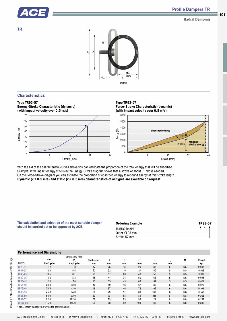
Profile Body
Mounting Screw
Profi le Dampers TR
Radial Damping
Stroke (mm)
Ener
gy (N
m)
70
60
50
40
30
20
10
0 8 16 32 44
Stroke (mm)
Forc
e (N
)6000
5000
4000
3000
2000
1000
0 8 16 32 44
F in
F backrebound stroke energy
absorbed energy
Characteristics
Ordering Example TR93-57TUBUS RadialOuter-Ø 93 mmStroke 57 mm
The calculation and selection of the most suitable damper should be carried out or be approved by ACE.
With the aid of the characteristic curves above you can estimate the proportion of the total energy that will be absorbed.Example: With impact energy of 50 Nm the Energy-Stroke diagram shows that a stroke of about 31 mm is needed.On the Force-Stroke diagram you can estimate the proportion of absorbed energy to rebound energy at this stroke length.Dynamic (v > 0.5 m/s) and static (v ≤ 0.5 m/s) characteristics of all types are available on request.
Type TR93-57Energy-Stroke Characteristic (dynamic)(with impact velocity over 0.5 m/s)
Type TR93-57Force-Stroke Characteristic (dynamic)(with impact velocity over 0.5 m/s)
Performance and Dimensions
TYPES
1 W3Nm/cycle
Emergency stopW3
Nm/cycleStroke max.
mmA
mmB
mmC
mmD
mmLM
mmM Weight
kgTR29-17 1.2 1.8 17 25 13 29 38 5 M5 0.006TR37-22 2.3 5.4 22 32 19 37 50 5 M5 0.013TR43-25 3.5 8.1 25 37 20 43 58 5 M5 0.017TR50-35 5.8 8.3 35 44 34 50 68 5 M5 0.026TR63-43 12.0 17.0 43 55 43 63 87 5 M5 0.051TR67-40 23.0 33.0 40 59 46 67 88 5 M5 0.077TR76-46 34.5 43.0 46 67 46 76 102 6 M6 0.104TR83-50 45.0 74.0 50 73 51 83 109 6 M6 0.142TR85-50 68.0 92.0 50 73 68 85 111 8 M8 0.206TR93-57 92.0 122.0 57 83 83 93 124 8 M8 0.297TR100-60 115.0 146.0 60 88 82 100 133 8 M8 0.335
1 Max. energy capacity per cycle for continous use.
C
LM A
Max.Stroke
M
D
Width B
TR
101Is
sue
08.2
016
– Sp
ecifi
catio
ns s
ubje
ct to
cha
nge
ACE Stoßdämpfer GmbH . PO Box 1510 . D-40740 Langenfeld . T +49 (0)2173 - 9226-4100 . F +49 (0)2173 - 9226-89 . [email protected] . www.ace-ace.com

Profile Body
Mounting Screw
Technical Data
Harder mixture of materials for higher energy absorption: The maintenance-free and ready-to-install TR-H-Series profi le dampers, are stressed radially in the same way as the basic TR model. With almost the same dimensions, they also decelerate with a very long and soft action. The harder co-polyester elastomer mixture leads to signifi cantly high energy absorption of 2.7 Nm to 427 Nm in these models. Easy to mount due to the supplied special screw.
The TR-H-Series is space-saving with dimen-sions of Ø 30 mm to Ø 102 mm. It comple-ments the TUBUS range between the progres-sive TR and almost linear TS models. Users are therefore provided with a full range of deceleration curves within the ACE TUBUS family.
The TUBUS TR-H products are suitable end position dampers in linear axes, in toolmaking and tool machines and in hydraulic, pneumatic and handling equipment as well as other applications.
TUBUS TR-HProfi le Dampers Compact size with soft deceleration and high energy absorption
Profi le Dampers
Radial Damping, Hard Version
Energy capacity: 2.7 Nm/Cycle to 427 Nm/CycleEnergy absorption: 39 % to 62 %Dynamic force range: 550 N to 21,200 NOperating temperature range: -40 °C to +90 °CConstruction size: 30 mm to 102 mmMounting: In any positionMaterial hardness rating: Shore 55DMaterial: Profi le body: Co-Polyester ElastomerEnvironment: Resistant to microbes, seawater or chemical attack. Excellent UV
and ozone resistance. Material does not absorb water or swell.Impact velocity range: Max. 5 m/sTorque max.: M5: 3 Nm M6: 6 Nm M8: 20 NmApplication fi eld: Furniture industry, Sports equipment, Linear slides, Pneumatic cylindersNote: Suitable for emergency stop applica-tions and for continous use. For applications with preloading and increased temperatures please consult ACE.
Safety instructions: Mounting screw should additionally be secured with Loctite.On request: Special strokes, -characteristics, -spring rates, -sizes and -materials.
102
Issu
e 08
.201
6 –
Spec
ifi ca
tions
sub
ject
to c
hang
e
ACE Stoßdämpfer GmbH . PO Box 1510 . D-40740 Langenfeld . T +49 (0)2173 - 9226-4100 . F +49 (0)2173 - 9226-89 . [email protected] . www.ace-ace.com
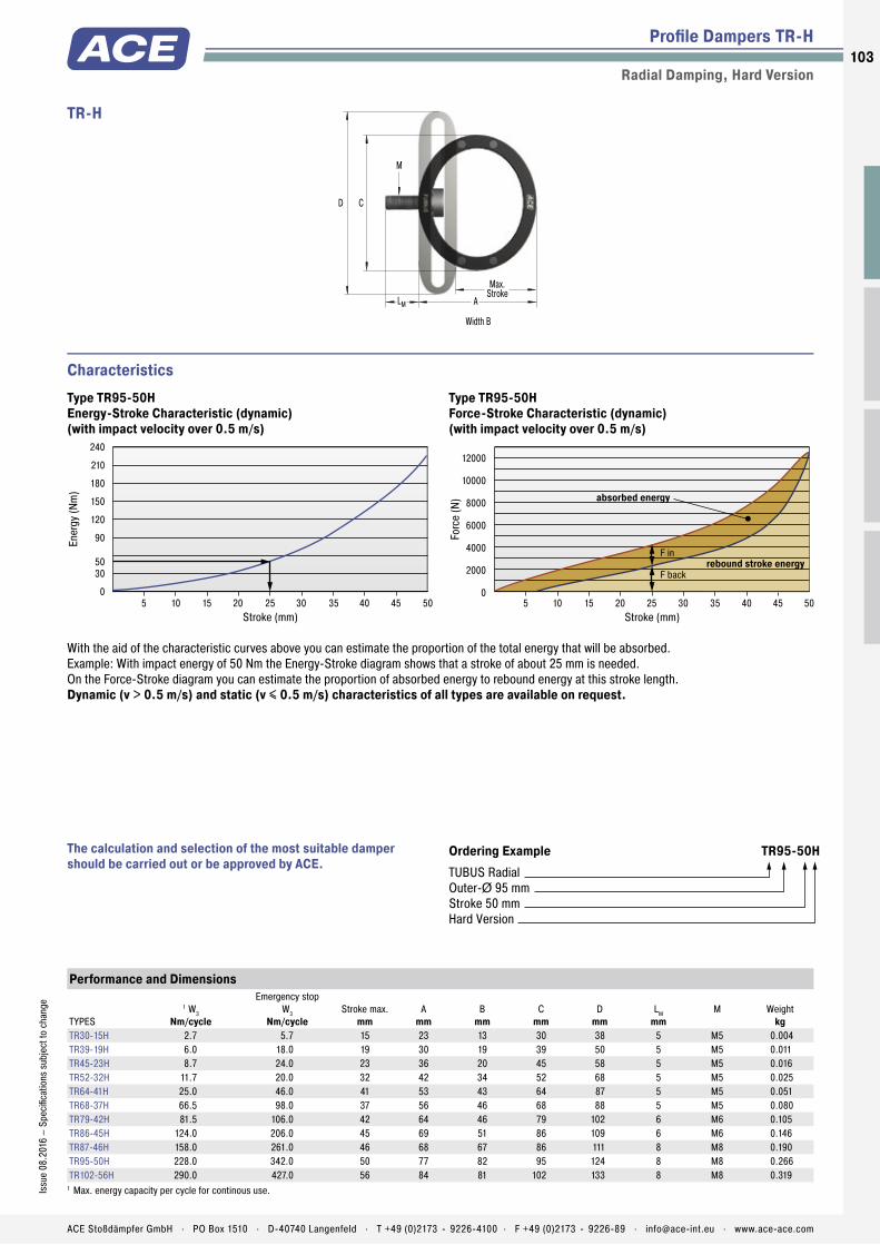
Profile Body
Mounting Screw
Profi le Dampers TR-H
Radial Damping, Hard Version
Stroke (mm)
Ener
gy (N
m)
240
210
180
150
120
90
5030
0 5 10 15 20 25 30 35 40 45 50
12000
10000
8000
6000
4000
2000
0 5 10 15 20 25 30 35 40 45 50
Stroke (mm)
Forc
e (N
) absorbed energy
rebound stroke energyF back
F in
Characteristics
Ordering Example TR95-50HTUBUS Radial Outer-Ø 95 mmStroke 50 mmHard Version
The calculation and selection of the most suitable damper should be carried out or be approved by ACE.
With the aid of the characteristic curves above you can estimate the proportion of the total energy that will be absorbed.Example: With impact energy of 50 Nm the Energy-Stroke diagram shows that a stroke of about 25 mm is needed.On the Force-Stroke diagram you can estimate the proportion of absorbed energy to rebound energy at this stroke length.Dynamic (v > 0.5 m/s) and static (v ≤ 0.5 m/s) characteristics of all types are available on request.
Type TR95-50HEnergy-Stroke Characteristic (dynamic)(with impact velocity over 0.5 m/s)
Type TR95-50HForce-Stroke Characteristic (dynamic)(with impact velocity over 0.5 m/s)
Performance and Dimensions
TYPES
1 W3Nm/cycle
Emergency stopW3
Nm/cycleStroke max.
mmA
mmB
mmC
mmD
mmLM
mmM Weight
kgTR30-15H 2.7 5.7 15 23 13 30 38 5 M5 0.004TR39-19H 6.0 18.0 19 30 19 39 50 5 M5 0.011TR45-23H 8.7 24.0 23 36 20 45 58 5 M5 0.016TR52-32H 11.7 20.0 32 42 34 52 68 5 M5 0.025TR64-41H 25.0 46.0 41 53 43 64 87 5 M5 0.051TR68-37H 66.5 98.0 37 56 46 68 88 5 M5 0.080TR79-42H 81.5 106.0 42 64 46 79 102 6 M6 0.105TR86-45H 124.0 206.0 45 69 51 86 109 6 M6 0.146TR87-46H 158.0 261.0 46 68 67 86 111 8 M8 0.190TR95-50H 228.0 342.0 50 77 82 95 124 8 M8 0.266TR102-56H 290.0 427.0 56 84 81 102 133 8 M8 0.319
1 Max. energy capacity per cycle for continous use.
C
LM A
Max.Stroke
M
D
Width B
TR-H
103Is
sue
08.2
016
– Sp
ecifi
catio
ns s
ubje
ct to
cha
nge
ACE Stoßdämpfer GmbH . PO Box 1510 . D-40740 Langenfeld . T +49 (0)2173 - 9226-4100 . F +49 (0)2173 - 9226-89 . [email protected] . www.ace-ace.com
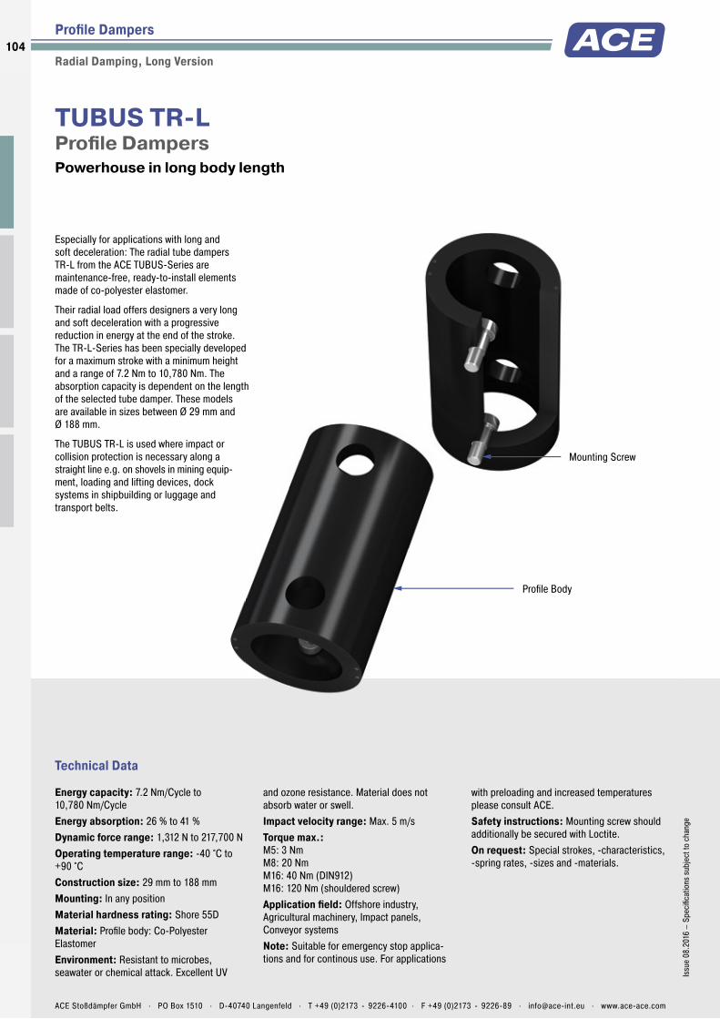
Profile Body
Mounting Screw
Technical Data
Especially for applications with long and soft deceleration: The radial tube dampers TR-L from the ACE TUBUS-Series are maintenance-free, ready-to-install elements made of co-polyester elastomer.
Their radial load offers designers a very long and soft deceleration with a progressive reduction in energy at the end of the stroke. The TR-L-Series has been specially developed for a maximum stroke with a minimum height and a range of 7.2 Nm to 10,780 Nm. The absorption capacity is dependent on the length of the selected tube damper. These models are available in sizes between Ø 29 mm and Ø 188 mm.
The TUBUS TR-L is used where impact or collision protection is necessary along a straight line e.g. on shovels in mining equip-ment, loading and lifting devices, dock systems in shipbuilding or luggage and transport belts.
TUBUS TR-LProfi le Dampers Powerhouse in long body length
Profi le Dampers
Radial Damping, Long Version
Energy capacity: 7.2 Nm/Cycle to 10,780 Nm/CycleEnergy absorption: 26 % to 41 %Dynamic force range: 1,312 N to 217,700 NOperating temperature range: -40 °C to +90 °CConstruction size: 29 mm to 188 mmMounting: In any positionMaterial hardness rating: Shore 55DMaterial: Profi le body: Co-Polyester ElastomerEnvironment: Resistant to microbes, seawater or chemical attack. Excellent UV
and ozone resistance. Material does not absorb water or swell.Impact velocity range: Max. 5 m/sTorque max.: M5: 3 Nm M8: 20 Nm M16: 40 Nm (DIN912) M16: 120 Nm (shouldered screw)Application fi eld: Offshore industry, Agricultural machinery, Impact panels, Conveyor systemsNote: Suitable for emergency stop applica-tions and for continous use. For applications
with preloading and increased temperatures please consult ACE.Safety instructions: Mounting screw should additionally be secured with Loctite.On request: Special strokes, -characteristics, -spring rates, -sizes and -materials.
104
Issu
e 08
.201
6 –
Spec
ifi ca
tions
sub
ject
to c
hang
e
ACE Stoßdämpfer GmbH . PO Box 1510 . D-40740 Langenfeld . T +49 (0)2173 - 9226-4100 . F +49 (0)2173 - 9226-89 . [email protected] . www.ace-ace.com

Profile Body
Mounting Screw
Profi le Dampers TR-L
Radial Damping, Long Version
Ordering Example TR66-40L-2TUBUS Radial Outer-Ø 66 mmStroke 40 mmLong VersionLength 2 = 305 mm
The calculation and selection of the most suitable damper should be carried out or be approved by ACE.
Performance and Dimensions
TYPES
1 W3Nm/cycle
Emergency stopW3
Nm/cycleStroke max.
mmA
mmB
mmC
mmD
mmE
mmLM
mmM Weight
kgTR29-17L 7.2 10.9 17 25 80 29 38 40 5 M5 0.044TR43-25L 14.0 32.7 25 37 80 43 58 40 5 M5 0.072TR63-43L 21.9 32.0 43 55 80 63 87 40 5 M5 0.106TR66-40L-1 102.0 143.0 40 59 152 66 87 102 8 M8 0.027TR66-40L-2 204.0 286.0 40 59 305 66 87 254 8 M8 0.580TR66-40L-3 306.0 428.0 40 59 457 66 87 406 8 M8 0.830TR66-40L-4 408.0 571.0 40 59 610 66 87 559 8 M8 1.130TR66-40L-5 510.0 714.0 40 59 762 66 87 711 8 M8 1.330TR76-45L-1 145.0 203.0 45 68 152 76 100 102 8 M8 0.380TR76-45L-2 290.0 406.0 45 68 305 76 100 254 8 M8 0.696TR76-45L-3 435.0 609.0 45 68 457 76 100 406 8 M8 1.130TR76-45L-4 580.0 812.0 45 68 610 76 100 559 8 M8 1.430TR76-45L-5 725.0 1,015.0 45 68 762 76 100 711 8 M8 1.780TR83-48L-1 180.0 252.0 48 73 152 83 106 102 8 M8 0.480TR83-48L-2 360.0 504.0 48 73 305 83 106 254 8 M8 0.930TR83-48L-3 540.0 756.0 48 73 457 83 106 406 8 M8 1.380TR83-48L-4 720.0 1,008.0 48 73 610 83 106 559 8 M8 1.810TR83-48L-5 900.0 1,260.0 48 73 762 83 106 711 8 M8 2.260TR99-60L-1 270.0 378.0 60 88 152 99 130 102 16 M16 0.790TR99-60L-2 540.0 756.0 60 88 305 99 130 254 16 M16 1.290TR99-60L-3 810.0 1,134.0 60 88 457 99 130 406 16 M16 1.940TR99-60L-4 1,080.0 1,512.0 60 88 610 99 130 559 16 M16 2.660TR99-60L-5 1,350.0 1,890.0 60 88 762 99 130 711 16 M16 3.100TR99-60L-6 1,620.0 2,268.0 60 88 914 99 130 864 16 M16 3.700TR99-60L-7 1,890.0 2,646.0 60 88 1,067 99 130 1,016 16 M16 4.300TR143-86L-1 600.0 840.0 86 127 152 143 191 76 22 M16 1.440TR143-86L-2 1,200.0 1,680.0 86 127 305 143 191 203 22 M16 2.900TR143-86L-3 1,800.0 2,520.0 86 127 457 143 191 355 22 M16 3.880TR143-86L-4 2,400.0 3,360.0 86 127 610 143 191 508 22 M16 5.290TR143-86L-5 3,000.0 4,200.0 86 127 762 143 191 660 22 M16 6.590TR143-86L-6 3,600.0 5,040.0 86 127 914 143 191 812 22 M16 7.890TR143-86L-7 4,200.0 5,880.0 86 127 1,067 143 191 965 22 M16 9.190TR188-108L-1 1,100.0 1,540.0 108 165 152 188 245 76 26 M16 2.340TR188-108L-2 2,200.0 3,080.0 108 165 305 188 245 203 26 M16 4.640TR188-108L-3 3,300.0 4,620.0 108 165 457 188 245 355 26 M16 6.890TR188-108L-4 4,400.0 6,160.0 108 165 610 188 245 508 26 M16 9.190TR188-108L-5 5,500.0 7,700.0 108 165 762 188 245 660 26 M16 11.390TR188-108L-6 6,600.0 9,240.0 108 165 914 188 245 812 26 M16 13.640TR188-108L-7 7,700.0 10,780.0 108 165 1,067 188 245 965 26 M16 15.940
1 Max. energy capacity per cycle for continous use.
EB
C
LM
Max.Stroke
M
D
A
TR-L
105Is
sue
08.2
016
– Sp
ecifi
catio
ns s
ubje
ct to
cha
nge
ACE Stoßdämpfer GmbH . PO Box 1510 . D-40740 Langenfeld . T +49 (0)2173 - 9226-4100 . F +49 (0)2173 - 9226-89 . [email protected] . www.ace-ace.com

Profile Body
Mounting Screw
Technical Data
Impact and collision protection: The TR-HD profi le dampers are stressed in the same way as the basic model TR but offer a higher force and energy absorption with a shorter damping distance thanks to the solid design. Different damping characteristic curves can be achieved with two different co-polyester elastomer hardness levels. The slightly oval (bi-concave) shape also ensures a softer force intake.
This series absorbs a lot of energy despite the low height: a range of 405 Nm to 11,840 Nm is progressively covered by strokes of 12 mm to 44 mm. With two screws, included in the delivery, the damper can be easily and quickly fi xed both horizontally or vertically. The drill hole distance is adapted if required.
These dampers are used in agricultural technology and on shovels or break joints on construction machines as well as on loading and lifting or similar equipment.
TUBUS TR-HDProfi le Dampers Compact powerhouse in solid material
Profi le Dampers
Radial Damping, Heavy Duty Version
Energy capacity: 405 Nm/Cycle to 11,840 Nm/CycleEnergy absorption: 43 % to 72 %Dynamic force range: 78.800 N to 812,900 NOperating temperature range: -40 °C to +90 °CConstruction size: 42 mm to 117 mmMounting: In any positionMaterial hardness rating: Shore 40D, Shore 55DMaterial: Profi le body: Co-Polyester Elastomer
Environment: Resistant to microbes, seawater or chemical attack. Excellent UV and ozone resistance. Material does not absorb water or swell.Impact velocity range: Max. 5 m/sTorque max.: M10: 7 Nm M12: 12 NmApplication fi eld: Offshore industry, Agricultural machinery, Impact panels, Conveyor systemsNote: Suitable for emergency stop applica-tions and for continous use. For applications
with preloading and increased temperatures please consult ACE.Safety instructions: Mounting screw should additionally be secured with Loctite.On request: Special strokes, -characteristics, -spring rates, -sizes and -materials.
106
Issu
e 08
.201
6 –
Spec
ifi ca
tions
sub
ject
to c
hang
e
ACE Stoßdämpfer GmbH . PO Box 1510 . D-40740 Langenfeld . T +49 (0)2173 - 9226-4100 . F +49 (0)2173 - 9226-89 . [email protected] . www.ace-ace.com

Profile Body
Mounting Screw
Profi le Dampers TR-HD
Radial Damping, Heavy Duty Version
55050045040035030025020015010050
0 5 10 15 20 25 30 35 40
Stroke (mm)
Forc
e (k
N) TR52-14HD
TR47-17HD
TR105-28HD
TR97-35HD
Characteristics
Ordering Example TR63-24HDTUBUS RadialOuter-Ø 63 mmStroke 24 mmHeavy Duty Version
The calculation and selection of the most suitable damper should be carried out or be approved by ACE.
TUBUS Family TR-HD Force-Stroke Characteristics (static)
Performance and Dimensions
TYPES
1 W3Nm/cycle
Emergency stopW3
Nm/cycleF max. static
NStroke max.
mmA
mmB
mmC
mmD
mmE
mmLM
mmM Weight
kgTR42-14HD 405 567 63,900 14 34 148 14 59 102 20 M10 0.170TR47-12HD 857 1,200 149,600 12 31 150 47 58 102 19 M10 0.170TR47-17HD 850 1,190 122,100 17 32 150 47 70 102 24 M10 0.180TR52-14HD 1,634 2,288 304,500 14 29 153 52 69 102 22 M10 0.180TR57-21HD 1,194 1,672 104,800 21 48 149 57 79 102 18 M10 0.340TR62-15HD 2,940 4,116 245,000 15 40 153 62 77 102 16 M10 0.330TR62-19HD 2,940 4,116 389,900 19 41 152 62 94 102 16 M10 0.360TR63-24HD 2,061 2,885 194,400 24 46 153 63 92 102 20 M10 0.330TR72-26HD 1,700 2,380 124,800 26 59 149 72 98 102 23 M12 0.560TR79-20HD 2,794 3,912 289,300 20 54 153 79 98 102 24 M12 0.570TR79-31HD 2,975 4,165 226,600 31 58 155 79 112 102 23 M12 0.560TR85-33HD 2,526 3,536 146,100 33 71 150 85 111 102 23 M12 0.710TR89-21HD 4,438 6,213 477,400 21 48 162 89 112 102 22 M12 0.560TR90-37HD 3,780 5,292 240,700 37 69 155 90 128 102 23 M12 0.750TR93-24HD 3,421 4,789 302,500 24 64 155 93 115 102 23 M12 0.790TR97-31HD 7,738 10,833 575,200 31 63 159 97 129 102 21 M12 0.800TR97-35HD 2,821 3,949 152,800 35 82 151 97 131 102 20 M12 1.060TR102-44HD 4,697 6,576 254,500 44 81 156 102 147 102 22 M12 1.050TR105-28HD 5,641 7,897 427,600 28 72 156 105 126 102 21 M12 1.000TR117-30HD 8,457 11,840 639,100 30 66 166 117 143 102 25 M12 1.010
1 Max. energy capacity per cycle for continous use.
EB
C
LM
A
Max.Stroke
M
D
TR-HD
107Is
sue
08.2
016
– Sp
ecifi
catio
ns s
ubje
ct to
cha
nge
ACE Stoßdämpfer GmbH . PO Box 1510 . D-40740 Langenfeld . T +49 (0)2173 - 9226-4100 . F +49 (0)2173 - 9226-89 . [email protected] . www.ace-ace.com

Application Examples
Profi le Dampers
TA
Safe end position dampingACE TUBUS profi le dampers protect the integrated loading station on a new high speed machining centre. The ACE TUBUS damper is designed to prevent overrun on the high speed loading station of a Camshaft machining centre used in the automobile industry. In the event that the drive train fails during operation or incorrect data is inputted the ACE TUBUS damper absorbs the impact preventing costly damage to the machine. The TA98-40 TUBUS damper impressed engineers with this exceptionally long service life in operation. When used as an emergency stop the TUBUS damper can absorb up to 73 % of the impact energy.
m
P s
Safety with ultra high speed operation
TS
Safe braking of maintenance boatsThe maintenance of wind turbines in open seas has long resulted in damage to maintenance boats. Because of impact velocity and swell, an increase in the boat‘s mass of up to 20 percent must be taken into account when landing on a rigid mooring structure. It is only since the landing operation has been carried out with the aid of the ACE company’s TUBUS series that cable repair and maintenance work on wind turbines has been made safe for both personnel and equipment. TUBUS of the type TS84-43 are seawater resistant and can withstand ambient temperatures from -40 °C to + 90 °C.
m
s
Seawater-resistant, robust TUBUS profi le dampers made of co-polyester elastomer allow boats and crew to dock safely Wals Diving and Marine Service, 1970AC Ijmuiden, Netherlands
108
Issu
e 08
.201
6 –
Spec
ifi ca
tions
sub
ject
to c
hang
e
ACE Stoßdämpfer GmbH . PO Box 1510 . D-40740 Langenfeld . T +49 (0)2173 - 9226-4100 . F +49 (0)2173 - 9226-89 . [email protected] . www.ace-ace.com

Profi le Dampers
Application Examples
TS
Protection of drive used in space treadmillWhen training in zero gravity, a harness with bungee cords is used to ensure that trainees do not become disengaged. Three ACE profi le dampers with a linear-working facility are utilized in this case. One so-called TUBUS is positioned in the pneumatic cylinder, while the other two are put in place in the rest of the system. All the dampers have the task of protecting the system if the treadmill drive belts become damaged. Otherwise, the cylinder would reach a very high speed and become seriously damaged at the end of the stroke.
m
s
F
TUBUS are used to protect a fi tness machine in zero gravity QinetiQ Space nv, BE9150 Kruibeke, Belgium
TR
Gentle damping for electric scootersTUBUS profi le dampers make driving an e-scooter a real experience. The footboard of an electric scooter should be dampened to enable the driver to experience a comfortable ride even over potholes and other bumpy surfaces. Ideally, the characteristic line should be furnished with a soft increase in force over a long stroke. The elegant look of the scooter as well as the folding mechanism designed to save space have not allowed the use of feasible damper solutions up to now. Inferior alternatives such as rubber dampers made of polyurethane or simple steel springs could not be considered from the start. The TUBUS profi le damper TR52-32H offered the perfect solution with its compact construction design paired with progressive damping action.
m
s
Profi le dampers increase the riding comfort of an electric scooter
109Is
sue
08.2
016
– Sp
ecifi
catio
ns s
ubje
ct to
cha
nge
ACE Stoßdämpfer GmbH . PO Box 1510 . D-40740 Langenfeld . T +49 (0)2173 - 9226-4100 . F +49 (0)2173 - 9226-89 . [email protected] . www.ace-ace.com

110110
ACE Stoßdämpfer GmbH . PO Box 1510 . D-40740 Langenfeld . T +49 (0)2173 - 9226-4100 . [email protected] . www.ace-ace.com
Automation Control
ACE provides TUBUS profi le dampers in many variations. Special solu-tions for presses can now be cost-effectively achieved with down holder dampers, damping plugs, lift dampers and press dampers from ACE.
They replace the PU-springs previously used in the automotive industry. It was no longer possible for them to fulfi l the required tasks due to the higher return stroke speeds in modern pressing tools. Made of co-polyester elastomers, the TUBUS special takes care of the protection of mounting bolts and insert bolts much more reliably. On the one hand they protect a so-called down holders during the return stroke after the forming of sheet metal parts, and on the other they function as protection for hoisting lifters.
Special Profi le Dampers Costs-effective tuning for your pressing tools
High reliability
Long service life
High power and energy absorption
Effi cient working through higher cycle rates
Noise reduction
Extreme abrasion hardness and shear strength
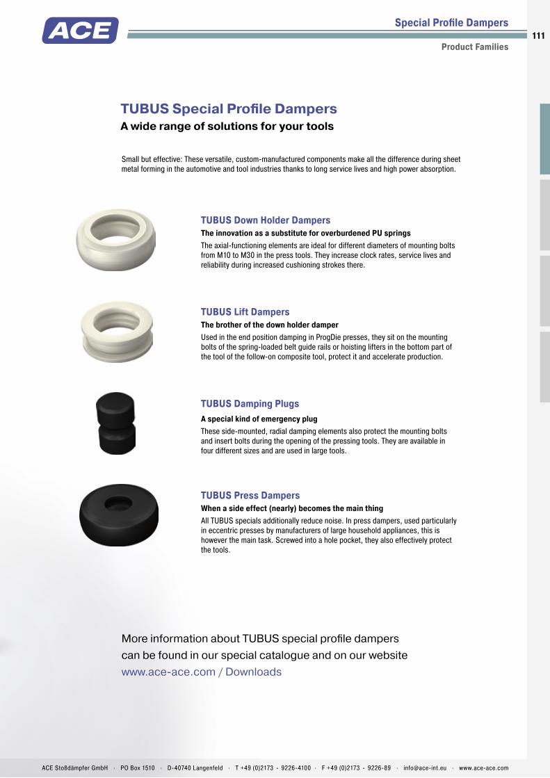
ACE Stoßdämpfer GmbH . PO Box 1510 . D-40740 Langenfeld . T +49 (0)2173 - 9226-4100 . F +49 (0)2173 - 9226-89 . [email protected] . www.ace-ace.com
111
TUBUS Special Profi le Dampers A wide range of solutions for your tools
More information about TUBUS special profi le dampers can be found in our special catalogue and on our websitewww.ace-ace.com / Downloads
Small but effective: These versatile, custom-manufactured components make all the difference during sheet metal forming in the automotive and tool industries thanks to long service lives and high power absorption.
TUBUS Down Holder DampersThe innovation as a substitute for overburdened PU springs The axial-functioning elements are ideal for different diameters of mounting bolts from M10 to M30 in the press tools. They increase clock rates, service lives and reliability during increased cushioning strokes there.
TUBUS Lift DampersThe brother of the down holder damper Used in the end position damping in ProgDie presses, they sit on the mounting bolts of the spring-loaded belt guide rails or hoisting lifters in the bottom part of the tool of the follow-on composite tool, protect it and accelerate production.
TUBUS Damping Plugs A special kind of emergency plug These side-mounted, radial damping elements also protect the mounting bolts and insert bolts during the opening of the pressing tools. They are available in four different sizes and are used in large tools.
TUBUS Press Dampers When a side effect (nearly) becomes the main thing All TUBUS specials additionally reduce noise. In press dampers, used particularly in eccentric presses by manufacturers of large household appliances, this is however the main task. Screwed into a hole pocket, they also effectively protect the tools.
Special Profi le Dampers
Product Families
High reliability
Long service life
Noise reduction
Extreme abrasion hardness and shear strength
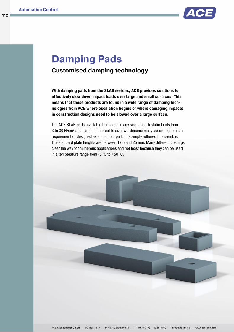
112112
ACE Stoßdämpfer GmbH . PO Box 1510 . D-40740 Langenfeld . T +49 (0)2173 - 9226-4100 . [email protected] . www.ace-ace.com
Damping PadsCustomised damping technology
With damping pads from the SLAB serices, ACE provides solutions to effectively slow down impact loads over large and small surfaces. This means that these products are found in a wide range of damping tech-nologies from ACE where oscillation begins or where damaging impacts in construction designs need to be slowed over a large surface.
The ACE SLAB pads, available to choose in any size, absorb static loads from 3 to 30 N/cm² and can be either cut to size two-dimensionally according to each requirement or designed as a moulded part. It is simply adhered to assemble. The standard plate heights are between 12.5 and 25 mm. Many different coatings clear the way for numerous applications and not least because they can be used in a temperature range from -5 °C to +50 °C.
Automation Control

ACE Stoßdämpfer GmbH . PO Box 1510 . D-40740 Langenfeld . T +49 (0)2173 - 9226-4100 . F +49 (0)2173 - 9226-89 . [email protected] . www.ace-ace.com
113Pad Cutting and Special Solutions
Damping Pads
Can be integrated quickly and cost-effectively
Immense inner damping
Pad thicknesses up to 80 mm on request
Can be assembled with CNC cutting machines
Patented formula
Environmentally-friendly H2O-foamed
Ask for special solutions !!!Individual Pad CuttingSLAB pads pre-assembled for each project
Whether pads, cuts or drawing parts, stocked SLAB pads in combination with our freely programmable cutting machine ensure maximum fl exibility with excellent delivery speed.
Fast, fl exible and adapted to your conditions.

Technical Data
Tailor made damping material in pad format: SLAB damping pads are made of a viscoelastic PUR-material. They absorb impact loads extremely effectively and are also suitable for insulating or damping vibration.
The pad series SL-030 to 300 are quickly adapted to the relevant type of application. This is in part achieved through the confi gura-tion of the calculating tool or directly by the ACE specialist engineers. Furthermore, this is possible because the standard material can be cut exactly and quickly to any customer requirement with our new cutting system. It is also possible to obtain a sample to fi nd an optimum solution.
The SLAB damping pads are proven impact or collision protection. They are used on luggage and transport belts, conveyor systems, pneumatic, electromechanical and hydraulic drives as well as on linear carriages.
SLAB-030 to SLAB-300Damping Pads Energy absorption in pad format
Damping Pads
Confectioning and Combinable
Energy capacity: 3.1 Nm/Cycle to 210 Nm/CycleStandard density: SL-030 = approx. 170 kg/m³SL-100 = approx. 340 kg/m³SL-300 = approx. 480 kg/m³Standard colour: GreenDimensions: Widths: up to 1,500 mmLengths: up to 5,000 mmThicknesses: 12.5 mm and 25 mmEnvironment: Resistant against ozone and UV radiation. Chemical resistancy on request.
Operating temperature range: -5 °C to +50 °CMaterial: Profi le body: Mixed cellular PUR-Elastomer (polyurethane)Application fi eld: Linear slides, Handling modules, Luggage and transport belts, Impact panelsNote: Possibilities for cutting: Water jet cutting, stamping, splitting, sawing and drillingSafety instructions: Fire rating: Class E, normally fl ammable, according to DIN 13501-2
On request: Special versions with further dimensions such as thicknesses, colours, shapes and drawing parts e.g. curves. Different wear layers.
114
Issu
e 08
.201
6 –
Spec
ifi ca
tions
sub
ject
to c
hang
e
ACE Stoßdämpfer GmbH . PO Box 1510 . D-40740 Langenfeld . T +49 (0)2173 - 9226-4100 . F +49 (0)2173 - 9226-89 . [email protected] . www.ace-ace.com

Damping Pads SL-030-12
Confectioning and Combinable
Stroke (mm)
Forc
e (k
N)
5.0
4.5
4.0
3.5
3.0
2.5
2.0
1.5
1.0
0.5
0
25
20
15
10
5
0
0 1.0 2.0 3.0 4.0 5.0 6.0 7.0
Ener
gy (N
m)
MP3
MP2
MP1
Characteristics Type SL-030-12Force-Stroke Characteristic (dynamic)Stroke Utilization 6.5 mm
Ordering Example SL-030-12-DxxxxACE-SLABMaterial TypeMaterial Thickness 12.5 mmCustomers Specific Dimension/Shape(D-Number is assigned by ACE)
The chosen damping plate should be tested by the customer on the specifi c application.
10,000 mm2
5,000 mm2
2,500 mm2
AreaAreaArea
Load dataDynamic load, impact velocity: approx. 1 m/s
Performance and Dimensions
TYPES
1 W3 max.Nm/cycle
1 Strokemm
Amm
Bmm
Cmm
Areamm2
Standard densitykg/m3
Return times
Weightkg
SL-030-12-D-MP1 3.1 6.5 50.0 50.0 12.5 2,500 170 4 0.006SL-030-12-D-MP2 8.0 6.5 70.7 70.7 12.5 5,000 170 4 0.011SL-030-12-D-MP3 19.0 6.5 100.0 100.0 12.5 10,000 170 4 0.021
1 Maximum energy absorption in terms of area graded pad sizes as a reference for the correct selection of material and pad size. The energy absorption depends on the individual impact surface and stroke utilization.
A
B
C
SL-030-12
115Is
sue
08.2
016
– Sp
ecifi
catio
ns s
ubje
ct to
cha
nge
ACE Stoßdämpfer GmbH . PO Box 1510 . D-40740 Langenfeld . T +49 (0)2173 - 9226-4100 . F +49 (0)2173 - 9226-89 . [email protected] . www.ace-ace.com

Damping Pads SL-030-25
Confectioning and Combinable
Stroke (mm)
Forc
e (k
N)
4.5
4.0
3.5
3.0
2.5
2.0
1.5
1.0
0.5
0
45
40
35
30
25
20
15
10
5
0
0 2.0 4.0 6.0 8.0 10.0 12.0
Ener
gy (N
m)MP3
MP2
MP1
Characteristics Type SL-030-25Force-Stroke Characteristic (dynamic)Stroke Utilization 12.5 mm
Ordering Example SL-030-25-DxxxxACE-SLABMaterial TypeMaterial Thickness 25 mmCustomers Specific Dimension/Shape(D-Number is assigned by ACE)
The chosen damping plate should be tested by the customer on the specifi c application.
10,000 mm2
5,000 mm2
2,500 mm2
AreaAreaArea
Load dataDynamic load, impact velocity: approx. 1 m/s
Performance and Dimensions
TYPES
1 W3 max.Nm/cycle
1 Strokemm
Amm
Bmm
Cmm
Areamm2
Standard densitykg/m3
Return times
Weightkg
SL-030-25-D-MP1 6.7 12.5 50.0 50.0 25.0 2,500 170 5 0.011SL-030-25-D-MP2 15.0 12.5 70.7 70.7 25.0 5,000 170 5 0.021SL-030-25-D-MP3 42.0 12.5 100.0 100.0 25.0 10,000 170 5 0.043
1 Maximum energy absorption in terms of area graded pad sizes as a reference for the correct selection of material and pad size. The energy absorption depends on the individual impact surface and stroke utilization.
A
B
C
SL-030-25
116
Issu
e 08
.201
6 –
Spec
ifi ca
tions
sub
ject
to c
hang
e
ACE Stoßdämpfer GmbH . PO Box 1510 . D-40740 Langenfeld . T +49 (0)2173 - 9226-4100 . F +49 (0)2173 - 9226-89 . [email protected] . www.ace-ace.com
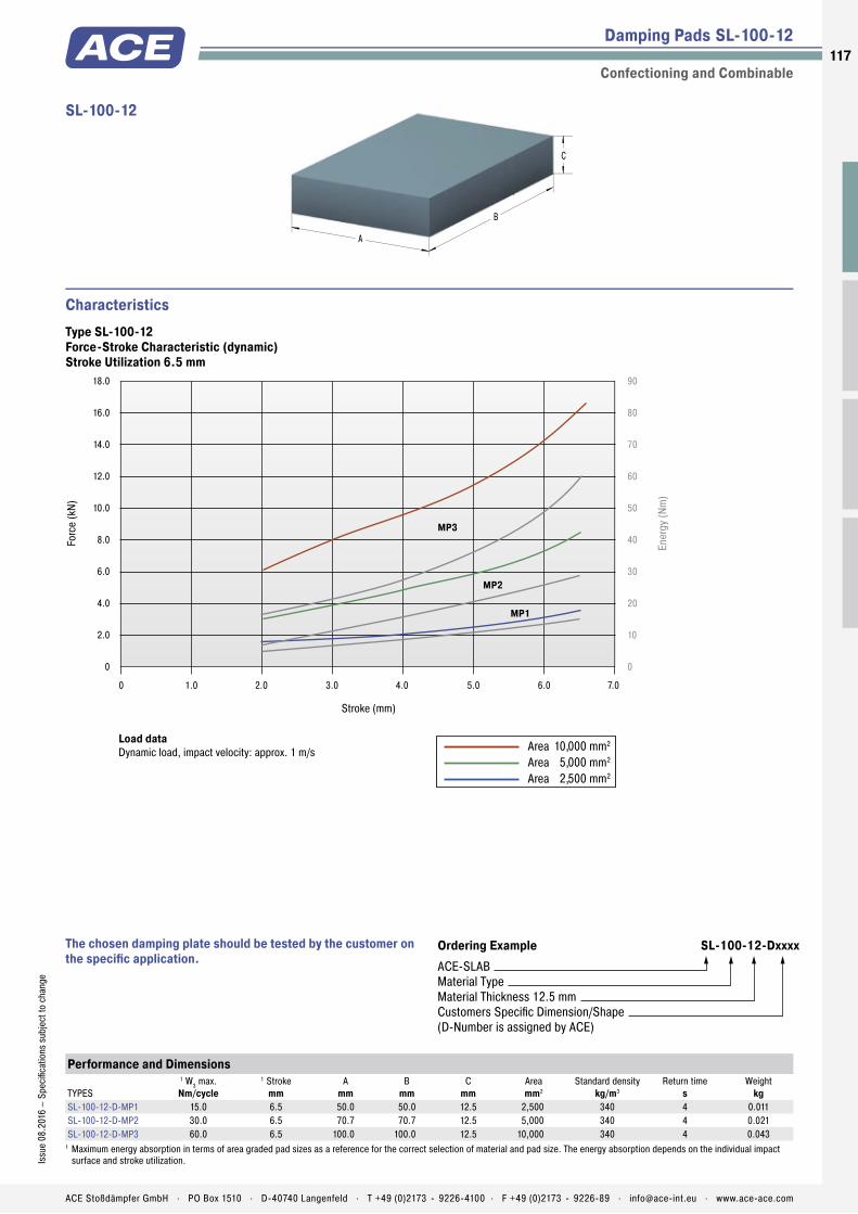
Damping Pads SL-100-12
Confectioning and Combinable
Stroke (mm)
Forc
e (k
N)
18.0
16.0
14.0
12.0
10.0
8.0
6.0
4.0
2.0
0
90
80
70
60
50
40
30
20
10
0
0 1.0 2.0 3.0 4.0 5.0 6.0 7.0
Ener
gy (N
m)
MP3
MP2
MP1
Characteristics Type SL-100-12Force-Stroke Characteristic (dynamic)Stroke Utilization 6.5 mm
Ordering Example SL-100-12-DxxxxACE-SLABMaterial TypeMaterial Thickness 12.5 mmCustomers Specific Dimension/Shape(D-Number is assigned by ACE)
The chosen damping plate should be tested by the customer on the specifi c application.
10,000 mm2
5,000 mm2
2,500 mm2
AreaAreaArea
Load dataDynamic load, impact velocity: approx. 1 m/s
Performance and Dimensions
TYPES
1 W3 max.Nm/cycle
1 Strokemm
Amm
Bmm
Cmm
Areamm2
Standard densitykg/m3
Return times
Weightkg
SL-100-12-D-MP1 15.0 6.5 50.0 50.0 12.5 2,500 340 4 0.011SL-100-12-D-MP2 30.0 6.5 70.7 70.7 12.5 5,000 340 4 0.021SL-100-12-D-MP3 60.0 6.5 100.0 100.0 12.5 10,000 340 4 0.043
1 Maximum energy absorption in terms of area graded pad sizes as a reference for the correct selection of material and pad size. The energy absorption depends on the individual impact surface and stroke utilization.
A
B
C
SL-100-12
117Is
sue
08.2
016
– Sp
ecifi
catio
ns s
ubje
ct to
cha
nge
ACE Stoßdämpfer GmbH . PO Box 1510 . D-40740 Langenfeld . T +49 (0)2173 - 9226-4100 . F +49 (0)2173 - 9226-89 . [email protected] . www.ace-ace.com
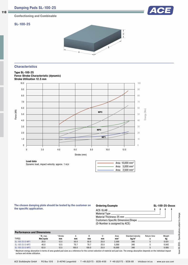
Damping Pads SL-100-25
Confectioning and Combinable
Stroke (mm)
Forc
e (k
N)
10.0
9.0
8.0
7.0
6.0
5.0
4.0
3.0
2.0
1.0
0
100
90
80
70
60
50
40
30
20
10
0
0 2.0 4.0 6.0 8.0 10.0 12.0
Ener
gy (N
m)
MP3
MP2
MP1
Characteristics Type SL-100-25Force-Stroke Characteristic (dynamic)Stroke Utilization 12.5 mm
Ordering Example SL-100-25-DxxxxACE-SLABMaterial TypeMaterial Thickness 25 mmCustomers Specific Dimension/Shape(D-Number is assigned by ACE)
The chosen damping plate should be tested by the customer on the specifi c application.
10,000 mm2
5,000 mm2
2,500 mm2
AreaAreaArea
Load dataDynamic load, impact velocity: approx. 1 m/s
Performance and Dimensions
TYPES
1 W3 max.Nm/cycle
1 Strokemm
Amm
Bmm
Cmm
Areamm2
Standard densitykg/m3
Return times
Weightkg
SL-100-25-D-MP1 20.0 12.5 50.0 50.0 25.0 2,500 340 5 0.021SL-100-25-D-MP2 40.0 12.5 70.7 70.7 25.0 5,000 340 5 0.042SL-100-25-D-MP3 63.0 12.5 100.0 100.0 25.0 10,000 340 5 0.085
1 Maximum energy absorption in terms of area graded pad sizes as a reference for the correct selection of material and pad size. The energy absorption depends on the individual impact surface and stroke utilization.
A
B
C
SL-100-25
118
Issu
e 08
.201
6 –
Spec
ifi ca
tions
sub
ject
to c
hang
e
ACE Stoßdämpfer GmbH . PO Box 1510 . D-40740 Langenfeld . T +49 (0)2173 - 9226-4100 . F +49 (0)2173 - 9226-89 . [email protected] . www.ace-ace.com

Damping Pads SL-300-12
Confectioning and Combinable
Stroke (mm)
Forc
e (k
N)
45.0
40.0
35.0
30.0
25.0
20.0
15.0
10.0
5.0
0
180
160
140
120
100
80
60
40
20
0
0 1.0 2.0 3.0 4.0 5.0 6.0 7.0
Ener
gy (N
m)MP3
MP2
MP1
Characteristics Type SL-300-12Force-Stroke Characteristic (dynamic)Stroke Utilization 6.5 mm
Ordering Example SL-300-12-DxxxxACE-SLABMaterial TypeMaterial Thickness 12.5 mmCustomers Specific Dimension/Shape(D-Number is assigned by ACE)
The chosen damping plate should be tested by the customer on the specifi c application.
10,000 mm2
5,000 mm2
2,500 mm2
AreaAreaArea
Load dataDynamic load, impact velocity: approx. 1 m/s
Performance and Dimensions
TYPES
1 W3 max.Nm/cycle
1 Strokemm
Amm
Bmm
Cmm
Areamm2
Standard densitykg/m3
Return times
Weightkg
SL-300-12-D-MP1 38.0 6.5 50.0 50.0 12.5 2,500 480 3 0.015SL-300-12-D-MP2 65.0 6.5 70.7 70.7 12.5 5,000 480 3 0.030SL-300-12-D-MP3 121.0 6.5 100.0 100.0 12.5 10,000 480 3 0.060
1 Maximum energy absorption in terms of area graded pad sizes as a reference for the correct selection of material and pad size. The energy absorption depends on the individual impact surface and stroke utilization.
A
B
C
SL-300-12
119Is
sue
08.2
016
– Sp
ecifi
catio
ns s
ubje
ct to
cha
nge
ACE Stoßdämpfer GmbH . PO Box 1510 . D-40740 Langenfeld . T +49 (0)2173 - 9226-4100 . F +49 (0)2173 - 9226-89 . [email protected] . www.ace-ace.com

Damping Pads SL-300-25
Confectioning and Combinable
Stroke (mm)
Forc
e (k
N)
45.0
37.5
30.0
22.5
15.0
7.5
0
300
250
200
150
100
50
0
0 1.0 2.0 3.0 4.0 5.0 6.0 7.0 8.0 9.0 10.0 11.0 12.0 13.0
Ener
gy (N
m)MP3
MP2
MP1
Characteristics Type SL-300-25Force-Stroke Characteristic (dynamic)Stroke Utilization 12.5 mm
Ordering Example SL-300-25-DxxxxACE-SLABMaterial TypeMaterial Thickness 25 mmCustomers Specific Dimension/Shape(D-Number is assigned by ACE)
The chosen damping plate should be tested by the customer on the specifi c application.
10,000 mm2
5,000 mm2
2,500 mm2
AreaAreaArea
Load dataDynamic load, impact velocity: approx. 1 m/s
Performance and Dimensions
TYPES
1 W3 max.Nm/cycle
1 Strokemm
Amm
Bmm
Cmm
Areamm2
Standard densitykg/m3
Return times
Weightkg
SL-300-25-D-MP1 59.0 12.5 50.0 50.0 25.0 2,500 480 4 0.030SL-300-25-D-MP2 101.0 12.5 70.7 70.7 25.0 5,000 480 4 0.060SL-300-25-D-MP3 210.0 12.5 100.0 100.0 25.0 10,000 480 4 0.120
1 Maximum energy absorption in terms of area graded pad sizes as a reference for the correct selection of material and pad size. The energy absorption depends on the individual impact surface and stroke utilization.
A
B
C
SL-300-25
120
Issu
e 08
.201
6 –
Spec
ifi ca
tions
sub
ject
to c
hang
e
ACE Stoßdämpfer GmbH . PO Box 1510 . D-40740 Langenfeld . T +49 (0)2173 - 9226-4100 . F +49 (0)2173 - 9226-89 . [email protected] . www.ace-ace.com

1. General Information
To achieve the required bonding strength it is necessary to ensure the correct adhesive is chosen for each individual application.Contact bonding material Thin adhesive film, with little filling of the gaps. Correcting or moving of the areas covered with bonding material is no longer possible after the first contact is made (contact effect).Once a bonding is separated, the bonding process must be renewed.Please note that creases, ripples or blisters cannot be straightened once the contact is made.Hardening bonding material (As thin as possible) the film of glue fills the joint. The gluing can be done after the edges are brought together.
2. Preparation
The preparation of bonding surfaces is of significant importance for the bonding strength. The surfaces must be adapted to each other and available in plain, clean form.Careful removal of Adhesive remnants, oil, fat,separating agents, dirt, dust, scales, molding layers, protective coating, finish, paint, sweat etc.Mechanical support Stripping, brushing, scraping, grinding, sandblasting.Chemical support Degreasing (washing off with grease remover), etching, priming; pay attention to chemical resistancy on the following page!In general, SLAB damping pads in sheet form can be bonded without pretreatment. Molded parts, with or without special skin, have to be cleaned from left-over separating agents, if necessary by grinding. When bonding with other materials like plastic, wood, metal or concrete, mechanical and/or chemical additives have to be used.The adhesive has to be prepared according to the formula, observing the manufacturer’s recommendations. The adhesive film is also to be carefully applied pursuant to these details. (Tools: brush, spatula, adhesive spreader, airless spray gun).Contact bonding material Apply the non-gap-filling adhesive film to both bonding surfaces – the thinner, the better. To close the pores of low density materials, two layers may be necessary.Hardening bonding material Apply evenly. Possible irregularities can be compensated by the film thickness.
Cellular and compact parts of polyurethane (PUR) elastomers SLAB damping pads can be bonded according to the following recommendations. If treatment instructions are followed, the strengths of the bonded joint can be equivalent to the elastomer material itself.
3. Bonding
When using contact bonding material, the flash off time has to be kept in mind. Especially, with systems containing water instead of usual solvents, the adhesive film must be as dry as possible in order to pass the ‘finger test’ – no marks appear when touching the adhesive surface. When using hardening bonding material, the parts have to be joined immediately after applying the bonding material.
4. Pressing
Contact bonding material Contact pressure up to 0.5 N/mm2 Hardening bonding material Fix firmlyIt is important to carefully follow the manufacturer’s instructions with regard to processing temperature, hardening time and earliest possible loading.
5. Selection of Approved Bonding Materials
Because of the variety of materials that can be bonded together as well as numerous suitable bonding materials, we refer you to a worldwide leading producer of bonding and sealing materials.
Sika Deutschland GmbH Kornwestheimer Straße 103–107 D-70439 StuttgartT +49 (0)711 - 8009-0 F +49 (0)711 - 8009-321 [email protected] http://www.sika.de
Bonding of Polyurethane (PUR) Elastomers
Damping Pads SLAB
Adhesive Recommendation and Technical Information121
Issu
e 08
.201
6 –
Spec
ifica
tions
sub
ject
to c
hang
e
ACE Stoßdämpfer GmbH . PO Box 1510 . D-40740 Langenfeld . T +49 (0)2173 - 9226-4100 . F +49 (0)2173 - 9226-89 . [email protected] . www.ace-ace.com
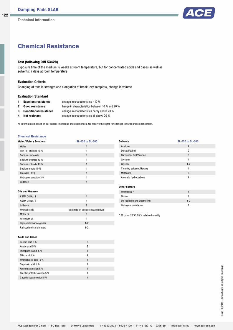
Chemical ResistanceWater/Watery Solutions SL-030 to SL-300
Water 1
Iron (III) chloride 10 % 1
Sodium carbonate 1
Sodium chlorate 10 % 1
Sodium chloride 10 % 1
Sodium nitrate 10 % 1
Tensides (div.) 1
Hydrogen peroxide 3 % 1
Laitance 1
Oils and Greases
ASTM Oil No. 1 1
ASTM Oil No. 3 1
Laitance 2
Hydraulic oils depends on consistency/additives
Motor oil 1
Formwork oil 1
High performance grease 1-2
Railroad switch lubricant 1-2
Acids and Bases
Formic acid 5 % 3
Acetic acid 5 % 2
Phosphoric acid 5 % 1
Nitic acid 5 % 4
Hydrochloric acid 5 % 1
Sulphuric acid 5 % 1
Ammonia solution 5 % 1
Caustic potash solution 5 % 1
Caustic soda solution 5 % 1
Solvents SL-030 to SL-300
Acetone 4
Diesel/Fuel oil 2
Carburetor fuel/Benzine 3
Glycerin 1
Glycols 1-2
Cleaning solvents/Hexane 1
Methanol 3
Aromatic hydrocarbons 4
Other Factors
Hydrolysis * 1
Ozone 1
UV radiation and weathering 1-2
Biological resistance 1
* 28 days, 70 °C, 95 % relative humidity
Test (following DIN 53428)Exposure time of the medium: 6 weeks at room temperature, but for concentrated acids and bases as well as solvents: 7 days at room temperature
Evaluation CriteriaChanging of tensile strength and elongation of break (dry samples), change in volume
Evaluation Standard1 Excellent resistance change in characteristics <10 % 2 Good resistance hange in characteristics between 10 % and 20 %3 Conditional resistance change in characteristics partly above 20 %4 Not resistant change in characteristics all above 20 %
All information is based on our current knowledge and experiences. We reserve the rights for changes towards product refinement.
Damping Pads SLAB
Technical Information
Chemical Resistance
122
Issu
e 08
.201
6 –
Spec
ifica
tions
sub
ject
to c
hang
e
ACE Stoßdämpfer GmbH . PO Box 1510 . D-40740 Langenfeld . T +49 (0)2173 - 9226-4100 . F +49 (0)2173 - 9226-89 . [email protected] . www.ace-ace.com
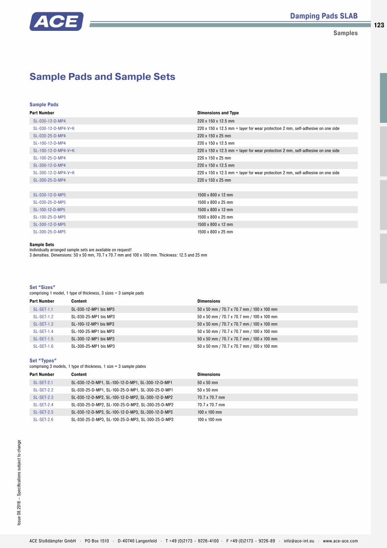
Set “Sizes” comprising 1 model, 1 type of thickness, 3 sizes = 3 sample pads
Part Number Content Dimensions
SL-SET-1.1 SL-030-12-MP1 bis MP3 50 x 50 mm / 70.7 x 70.7 mm / 100 x 100 mm
SL-SET-1.2 SL-030-25-MP1 bis MP3 50 x 50 mm / 70.7 x 70.7 mm / 100 x 100 mm
SL-SET-1.3 SL-100-12-MP1 bis MP3 50 x 50 mm / 70.7 x 70.7 mm / 100 x 100 mm
SL-SET-1.4 SL-100-25-MP1 bis MP3 50 x 50 mm / 70.7 x 70.7 mm / 100 x 100 mm
SL-SET-1.5 SL-300-12-MP1 bis MP3 50 x 50 mm / 70.7 x 70.7 mm / 100 x 100 mm
SL-SET-1.6 SL-300-25-MP1 bis MP3 50 x 50 mm / 70.7 x 70.7 mm / 100 x 100 mm
Set “Types” comprising 3 models, 1 type of thickness, 1 size = 3 sample plates
Part Number Content Dimensions
SL-SET-2.1 SL-030-12-D-MP1, SL-100-12-D-MP1, SL-300-12-D-MP1 50 x 50 mm
SL-SET-2.2 SL-030-25-D-MP1, SL-100-25-D-MP1, SL-300-25-D-MP1 50 x 50 mm
SL-SET-2.3 SL-030-12-D-MP2, SL-100-12-D-MP2, SL-300-12-D-MP2 70.7 x 70.7 mm
SL-SET-2.4 SL-030-25-D-MP2, SL-100-25-D-MP2, SL-300-25-D-MP2 70.7 x 70.7 mm
SL-SET-2.5 SL-030-12-D-MP3, SL-100-12-D-MP3, SL-300-12-D-MP3 100 x 100 mm
SL-SET-2.6 SL-030-25-D-MP3, SL-100-25-D-MP3, SL-300-25-D-MP3 100 x 100 mm
Damping Pads SLAB
Samples
Sample Pads and Sample Sets
Sample Pads Part Number Dimensions and Type
SL-030-12-D-MP4 220 x 150 x 12.5 mm
SL-030-12-D-MP4-V+K 220 x 150 x 12.5 mm + layer for wear protection 2 mm, self-adhesive on one side
SL-030-25-D-MP4 220 x 150 x 25 mm
SL-100-12-D-MP4 220 x 150 x 12.5 mm
SL-100-12-D-MP4-V+K 220 x 150 x 12.5 mm + layer for wear protection 2 mm, self-adhesive on one side
SL-100-25-D-MP4 220 x 150 x 25 mm
SL-300-12-D-MP4 220 x 150 x 12.5 mm
SL-300-12-D-MP4-V+K 220 x 150 x 12.5 mm + layer for wear protection 2 mm, self-adhesive on one side
SL-300-25-D-MP4 220 x 150 x 25 mm
SL-030-12-D-MP5 1500 x 800 x 12 mm
SL-030-25-D-MP5 1500 x 800 x 25 mm
SL-100-12-D-MP5 1500 x 800 x 12 mm
SL-100-25-D-MP5 1500 x 800 x 25 mm
SL-300-12-D-MP5 1500 x 800 x 12 mm
SL-300-25-D-MP5 1500 x 800 x 25 mm
Sample SetsIndividually arranged sample sets are available on request! 3 densities. Dimensions: 50 x 50 mm, 70.7 x 70.7 mm and 100 x 100 mm. Thickness: 12.5 and 25 mm
123Is
sue
08.2
016
– Sp
ecifi
catio
ns s
ubje
ct to
cha
nge
ACE Stoßdämpfer GmbH . PO Box 1510 . D-40740 Langenfeld . T +49 (0)2173 - 9226-4100 . F +49 (0)2173 - 9226-89 . [email protected] . www.ace-ace.com

Application Examples
Damping Pads
SL-030, TA
Damping combination SLAB and TUBUSSLAB-TUBUS-Combination ensures fast luggage transport. Airports endeavour to shorten air passengers’ waiting times as much as possible. This aim is met with a solution especially developed for luggage transport systems and has solved previous damping issue. Transport carriers with a weight of up to 120 kg can now be moved at the desired conveyor belt speeds. A SLAB-combination of the material SL-030-12(25)-Dxxxx together with two TA40-16 type TUBUS profi le dampers are used here.
Fast luggage transport for airport customers
SL-030
Noise reductionACE-SLAB damping pads protect man and machine. At the beginning of the construction phase of a modern processing centre at the end position, a 25 kg cable channel collided with force against the housing and produced a deafening noise and mechanical strain on the energy chain. A reliable solution for compliance with the operational parameters was realized with the SL-030-25-Dxxxx type ACE-SLAB damping pads even before the milling machine was fi nished.
m
s
Low-noise energy chain
124
Issu
e 08
.201
6 –
Spec
ifi ca
tions
sub
ject
to c
hang
e
ACE Stoßdämpfer GmbH . PO Box 1510 . D-40740 Langenfeld . T +49 (0)2173 - 9226-4100 . F +49 (0)2173 - 9226-89 . [email protected] . www.ace-ace.com
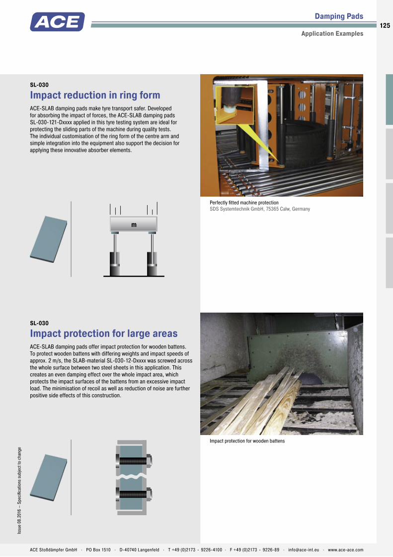
Damping Pads
Application Examples
SL-030
Impact reduction in ring formACE-SLAB damping pads make tyre transport safer. Developed for absorbing the impact of forces, the ACE-SLAB damping pads SL-030-121-Dxxxx applied in this tyre testing system are ideal for protecting the sliding parts of the machine during quality tests. The individual customisation of the ring form of the centre arm and simple integration into the equipment also support the decision for applying these innovative absorber elements.
m
Perfectly fi tted machine protection SDS Systemtechnik GmbH, 75365 Calw, Germany
SL-030
Impact protection for large areasACE-SLAB damping pads offer impact protection for wooden battens. To protect wooden battens with differing weights and impact speeds of approx. 2 m/s, the SLAB-material SL-030-12-Dxxxx was screwed across the whole surface between two steel sheets in this application. This creates an even damping effect over the whole impact area, which protects the impact surfaces of the battens from an excessive impact load. The minimisation of recoil as well as reduction of noise are further positive side effects of this construction.
Impact protection for wooden battens
125Is
sue
08.2
016
– Sp
ecifi
catio
ns s
ubje
ct to
cha
nge
ACE Stoßdämpfer GmbH . PO Box 1510 . D-40740 Langenfeld . T +49 (0)2173 - 9226-4100 . F +49 (0)2173 - 9226-89 . [email protected] . www.ace-ace.com
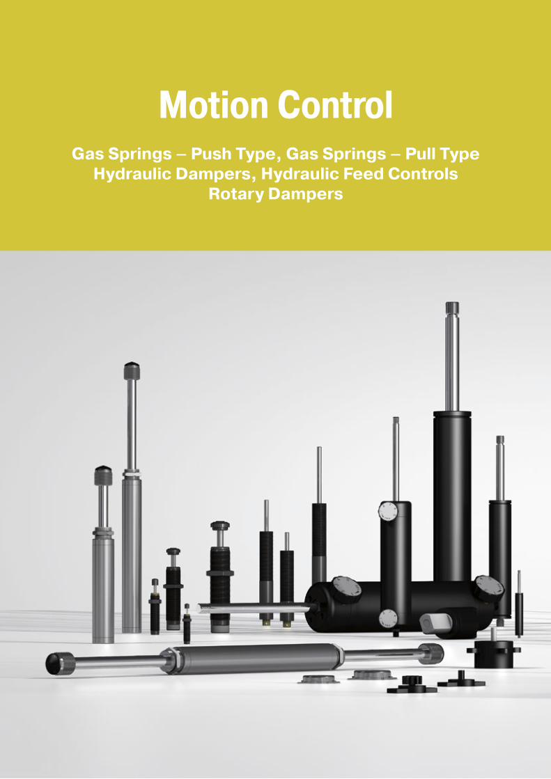
Motion ControlGas Springs – Push Type, Gas Springs – Pull Type
Hydraulic Dampers, Hydraulic Feed ControlsRotary Dampers

Perfect Support for Muscle Power Customised to suit your applications
The various products from ACE in this segment give a new quality to any type of movement. Anyone who wants to raise or lower loads, regulate the feed of an object to the precise millimetre or gently decelerate rotating or linear movements will find the right helper here.
ACE also convinces with industry quality in this area. And the inno-vative solutions also correspond with the maximum requirements of ergonomics and individuality, including with customised, fillable gas springs.

Industrial Gas Springs – Push TypeLifting and lowering for smart people
Anyone who wants to lift or lower loads with control and without excessive strength relies on the industrial gas push type springs from ACE. These maintenance-free, ready-to-install machine elements, which are available from stock, support sheer muscle power and reliably open and hold.
Available with body diameters of 8 to 70 mm and forces from 10 to 13,000 N, ACE gas push type springs are characterised by a huge variety and maximum service life. The fi rst is achieved thanks to the number of available connections and fi ttings for simple attachment and the latter with high quality design and materials. Whether they are made of steel or stainless steel, these components make any work easier and also make a particularly good impression visually in every branch.
Motion Control
Ready-to-install and universally applicable
Modular end fi ttings and mounting brackets
Calculation program for individual design
No own construction costs
Maintenance-free
Available with valve ex stock
128128
ACE Stoßdämpfer GmbH . PO Box 1510 . D-40740 Langenfeld . T +49 (0)2173 - 9226-4100 . [email protected] . www.ace-ace.com

Extension
55Total Stroke mm
F3FR
F1
F2
F4
Compression
Gas Springs (Push Type)Type Progression
approx. %1 Friction FR
approx. in NGS-8 28 10GS-10 20 10GS-12 25 20GS-15 27 20GS-19 26 - 39 2 30GS-22 30 - 40 2 30GS-28 58 - 67 2 40GS-40 37 - 49 2 50GS-70 25 50
1 Depending on the fi lling force 2 Depending on the stroke
Product Families
Overview
Industrial Gas Springs – Push Type
GS-8 to GS-70 Valve Technology Individual stroke length and extension forcesHoods, Shutters, Machine housing, Conveyor systems
Page 130
GS-8-V4A to GS-40-VA Valve Technology, Stainless Steel With food grade oil according to FDA approvalHoods, Shutters, Machine housing, Conveyor systems
Page 140
GST-40 Tandem Valve Technology Optimised dual force for heavy fl aps and wide angle applicationsHoods, Shutters, Machine housing, Conveyor systems
Page 150
Ready-to-install and universally applicable
Modular end fi ttings and mounting brackets
Calculation program for individual design
No own construction costs
Maintenance-free
Available with valve ex stock
Free calculation service see page 168!
F1 = nominal force at 20 °C (this is the pressure fi gure normally used when specifying the gas spring)
F2 = force in the complete compressed position When compressing the piston rod, there is an additional friction force caused by the contact pressure of the seals (this only occurs during the compression stroke): F3 = force at the beginning of the compression stroke F4 = force at the end of the compression stroke
Calculation Principles Force-Stroke Characteristics of Gas Spring (Push Type)
ACE gas springs are individually fi lled to a predetermined pressure to suit a customer’s require-ment (extension Force F1). The cross-sectional area of the piston rod and fi lling pressure determines the extension force. During the compression of the piston rod, nitrogen fl ows through an orifi ce in the piston from the full bore side of the piston to the annulus. The nitrogen is compressed by the volume of the piston rod. As the piston rod is compressed the pressure increases, so increasing the reaction force (progression). The force depends on the proportional relationship between the piston rod and the inner tube diameter, which is approximately linear.
Function of a Gas Spring – Push Type
Progression: (the slope of the force line in the diagram above) is due to the reduction of the internal gas volume as the piston rod moves from its initial position to its fully stroked position. The approx. progression values given above for standard springs can be altered on request. Effect of termperature: The nominal F1 fi gure is given at 20 °C. An increase of 10 °C will increase force by 3.4 %. Filling tolerances: 20 N to +40 N or 5 % to 7 %. Depending on size and extension force the tolerances can differ.
129Is
sue
08.2
016
– Sp
ecifi
catio
ns s
ubje
ct to
cha
nge
ACE Stoßdämpfer GmbH . PO Box 1510 . D-40740 Langenfeld . T +49 (0)2173 - 9226-4100 . F +49 (0)2173 - 9226-89 . [email protected] . www.ace-ace.com

Metering Orifice for Controlled Velocities
Filled with High Pressure Nitrogen Gas
Valve
Oil Zone for End Position Damping
Seals
Outer Body
Grease Chamber for Low Breakaway Force
Main Bearing
Piston Rod
Thread for End Fittings
Technical Data
Universal and tailor made: ACE industrial gas push type springs of the NEWTONLINE family offer perfect support of muscle power with forces from 10 to 13,000 N with body diameter of 8 to 70 mm. With their high quality features the NEWTONLINE gas springs form the industry standard. These durable and sealed systems are ready for installation, maintenance-free and fi lled with pressurised nitrogen gas.
They are supplied fi lled according to individual customer pressure requirements and maybe adjusted later by use of the inbuilt valve. The free of charge ACE calculation service designs the gas springs with mounting points specifi cally for the particular application. A variety of additional components makes assembly even easier and allows universal application of the gas springs.
ACE industrial gas push type springs are used in industrial applications, mechanical engineering and medical technology as well as in the electronics, automobile and furniture industries.
GS-8 to GS-70Industrial Gas Springs – Push Type Individual stroke length and extension forces
Industrial Gas Springs – Push Type
Valve Technology
Force range: 10 N to 13,000 NPiston rod diameter: Ø 3 mm to Ø 30 mmProgression: Approx. 20 % to 67 % (depending on size and stroke)Lifetime: Approx. 10,000 mOperating temperature range: -20 °C to +80 °CMaterial: Outer body: Coated steel; Piston rod: Steel or stainless steel with wear-resistant coating; End fi ttings: Zinc plated steelOperating fl uid: Nitrogen gas and oil
Mounting: We recommend mounting with piston rod downwards to take advantage of the built-in end position damping.End position damping length: Approx. 5 mm to 70 mm (depending on the stroke)Positive stop: External positive stop at the end of stroke provided by the customer.Application fi eld: Hoods, Shutters, Machine housing, Conveyor systemsNote: Increased break-away force if unit has not moved for some time.
End fi ttings: They are interchangeable and must be positively secured by the customer to prevent unscrewing.Safety instructions: Gas springs (push type) should not be installed under pre-tension.On request: Special oils and other special options. Alternative accessories. Different end position damping and extension speed.
130
Issu
e 08
.201
6 –
Spec
ifi ca
tions
sub
ject
to c
hang
e
ACE Stoßdämpfer GmbH . PO Box 1510 . D-40740 Langenfeld . T +49 (0)2173 - 9226-4100 . F +49 (0)2173 - 9226-89 . [email protected] . www.ace-ace.com

Metering Orifice for Controlled Velocities
Filled with High Pressure Nitrogen Gas
Valve
Oil Zone for End Position Damping
Seals
Outer Body
Grease Chamber for Low Breakaway Force
Main Bearing
Piston Rod
Thread for End Fittings
Industrial Gas Springs – Push Type GS-8
Valve Technology , Force range 10 N to 100 N (compressed up to 130 N)
End Fitting End FittingStandard Dimensions
5
24° 7,8 4
5
5.3
7 127.3
ØØ
7
1818
4
13 8
68
5
M3.5x0.6
18
8
8
12 L+/- 2 mm extended
3
4.1
StrokeRadiusR4
4 thick
12
4 thick
8 8
L = Stroke + 10
11
ØØ
Ø
Ø Ø
ØØ
4
8
4
5 16
8
Ø
Ø
Ø
18M4x0.7
8.5
13 8
6
10
36°
Ø Ø
5
4.1
16
12
A3,5
NG3,5
NA3,5
OG3,5
OA3,5
C3,5D3,5
E3,5G3,5
A3,5
Technical Data
Force range: 10 N to 100 N (compressed up to 130 N)Progression: Approx. 28 %Operating temperature range: -20 °C to +80 °CMaterial: Outer body: Coated steel; Piston rod: Stainless steel (1.4301/1.4305, AISI 304/303); End fi ttings: Zinc plated steelMounting: We recommend mounting with piston rod downwards to take advantage of the built-in end position damping.End position damping length: Approx. 5 mm (depending on the stroke)Positive stop: External positive stop at the end of stroke provided by the customer.Note: Increased break-away force if unit has not moved for some time.End fi ttings: They are interchangeable and must be positively secured by the customer to prevent unscrewing.Safety instructions: Gas springs (push type) should not be installed under pre-tension.
Performance and Dimensions
TYPESStroke
mmL extended
mmForce Range max.
NGS-8-20 20 72 100GS-8-30 30 92 100GS-8-40 40 112 100GS-8-50 50 132 100GS-8-60 60 152 100GS-8-80 80 192 100
Ordering Example GS-8-30-AC-30Type (Push Type)Body Ø (8 mm)Stroke (30 mm)Piston Rod End Fitting A3,5Body End Fitting C3,5Nominal Force F1 30 N
GS-8
Mounting accessories see from page 194.
Eye A3,5 max. force 370 N
A3,5
Stud Thread B3,5 B3,5
Angle Ball Joint C3,5 max. force 370 N
C3,5
Clevis Fork D3,5 max. force 370 N
D3,5
Swivel Eye E3,5 max. force 370 N
E3,5
Ball Socket G3,5 max. force 370 N
G3,5
Rod Shroud W3,5-8
Adjuster Knob DE-GAS-3,5
See page 171.
131Is
sue
08.2
016
– Sp
ecifi
catio
ns s
ubje
ct to
cha
nge
ACE Stoßdämpfer GmbH . PO Box 1510 . D-40740 Langenfeld . T +49 (0)2173 - 9226-4100 . F +49 (0)2173 - 9226-89 . [email protected] . www.ace-ace.com

Industrial Gas Springs – Push Type GS-10
Valve Technology , Force range 10 N to 100 N (compressed up to 120 N)
End Fitting End FittingStandard Dimensions
5
24° 7.8 4
5
5.3
7 127.3
ØØ
7
1818
4
13 8
68
5
M3.5x0.6
18
8
8
12 L+/- 2 mm extended
3
4.1
StrokeRadiusR4
4 thick
12
4 thick
10 8
L = Stroke + 10
13
ØØ
Ø
Ø Ø
ØØ
4
8
4
5 16
8
Ø
Ø
Ø
18M4x0.7
8.5
13 8
6
10
36°
Ø Ø
5
4.1
16
12
A3,5
NG3,5
NA3,5
OG3,5
OA3,5
C3,5D3,5
E3,5G3,5
A3,5
Technical Data
Force range: 10 N to 100 N (compressed up to 120 N)Progression: Approx. 28 %Operating temperature range: -20 °C to +80 °CMaterial: Outer body: Coated steel; Piston rod: Stainless steel (1.4301/1.4305, AISI 304/303); End fittings: Zinc plated steelMounting: We recommend mounting with piston rod downwards to take advantage of the built-in end position damping.End position damping length: Approx. 5 mm (depending on the stroke)Positive stop: External positive stop at the end of stroke provided by the customer.Note: Increased break-away force if unit has not moved for some time.End fittings: They are interchangeable and must be positively secured by the customer to prevent unscrewing.Safety instructions: Gas springs (push type) should not be installed under pre-tension.
Performance and Dimensions
TYPESStroke
mmL extended
mmForce Range max.
NGS-10-20 20 72 100GS-10-30 30 92 100GS-10-40 40 112 100GS-10-50 50 132 100GS-10-60 60 152 100GS-10-80 80 192 100
Ordering Example GS-10-80-AC-60Type (Push Type)Body Ø (10 mm)Stroke (80 mm)Piston Rod End Fitting A3,5Body End Fitting C3,5Nominal Force F1 60 N
GS-10
Mounting accessories see from page 194.
Eye A3,5 max. force 370 N
A3,5
Stud Thread B3,5 B3,5
Angle Ball Joint C3,5 max. force 370 N
C3,5
Clevis Fork D3,5 max. force 370 N
D3,5
Swivel Eye E3,5 max. force 370 N
E3,5
Ball Socket G3,5 max. force 370 N
G3,5
Rod Shroud W3,5-10
Adjuster Knob DE-GAS-3,5
See page 171.
132
Issu
e 08
.201
6 –
Spec
ifica
tions
sub
ject
to c
hang
e
ACE Stoßdämpfer GmbH . PO Box 1510 . D-40740 Langenfeld . T +49 (0)2173 - 9226-4100 . F +49 (0)2173 - 9226-89 . [email protected] . www.ace-ace.com

Industrial Gas Springs – Push Type GS-12
Valve Technology , Force range 15 N to 180 N (compressed up to 225 N)
End Fitting End FittingStandard Dimensions
5
24° 7.8 4
5
5.3
7 127.3
ØØ
7
1818
4
13 8
68
5
M3.5x0.6
18
8
8
12 L+/- 2 mm extended
4
4.1
StrokeRadiusR4
4 thick
12
4 thick
12 8
L = Stroke + 10
15.6
ØØ
Ø
Ø Ø
ØØ
4
8
4
5 16
8
Ø
Ø
Ø
18M4x0.7
8.5
13 8
6
10
36°
Ø Ø
5
4.1
16
12
A3,5
NG3,5
NA3,5
OG3,5
OA3,5
C3,5D3,5
E3,5G3,5
A3,5
Technical Data
Force range: 15 N to 180 N (compressed up to 225 N)Progression: Approx. 25 %Operating temperature range: -20 °C to +80 °CMaterial: Outer body: Coated steel; Piston rod: Stainless steel (1.4301/1.4305, AISI 304/303); End fittings: Zinc plated steelMounting: We recommend mounting with piston rod downwards to take advantage of the built-in end position damping.End position damping length: Approx. 10 mm (depending on the stroke)Positive stop: External positive stop at the end of stroke provided by the customer.Note: Increased break-away force if unit has not moved for some time.End fittings: They are interchangeable and must be positively secured by the customer to prevent unscrewing.Safety instructions: Gas springs (push type) should not be installed under pre-tension.
Performance and Dimensions
TYPESStroke
mmL extended
mmForce Range max.
NGS-12-20 20 72 180GS-12-30 30 92 180GS-12-40 40 112 180GS-12-50 50 132 180GS-12-60 60 152 180GS-12-80 80 192 150GS-12-100 100 232 150GS-12-120 120 272 120GS-12-150 150 332 100
Ordering Example GS-12-100-AA-30Type (Push Type)Body Ø (12 mm)Stroke (100 mm)Piston Rod End Fitting A3,5Body End Fitting A3,5Nominal Force F1 30 N
GS-12
Mounting accessories see from page 194.
Eye A3,5 max. force 370 N
A3,5
Stud Thread B3,5 B3,5
Angle Ball Joint C3,5 max. force 370 N
C3,5
Clevis Fork D3,5 max. force 370 N
D3,5
Swivel Eye E3,5 max. force 370 N
E3,5
Ball Socket G3,5 max. force 370 N
G3,5
Rod Shroud W3,5-12
Adjuster Knob DE-GAS-3,5
See page 171.
133Is
sue
08.2
016
– Sp
ecifi
catio
ns s
ubje
ct to
cha
nge
ACE Stoßdämpfer GmbH . PO Box 1510 . D-40740 Langenfeld . T +49 (0)2173 - 9226-4100 . F +49 (0)2173 - 9226-89 . [email protected] . www.ace-ace.com
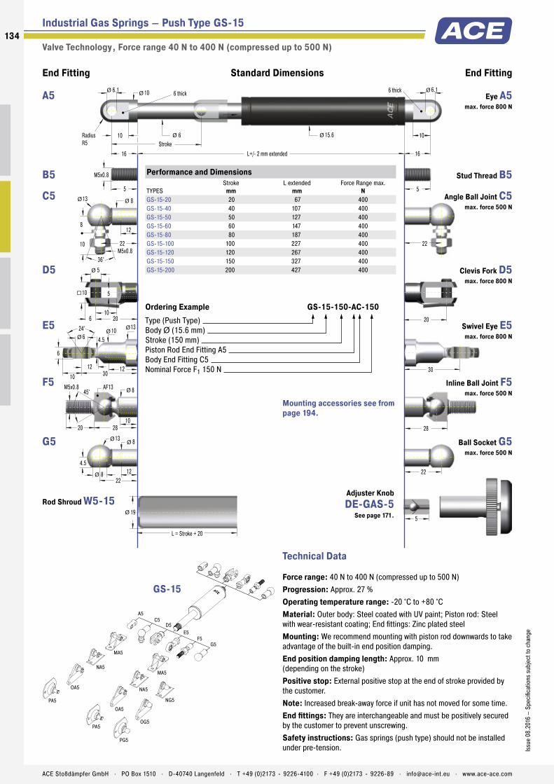
Industrial Gas Springs – Push Type GS-15
Valve Technology , Force range 40 N to 400 N (compressed up to 500 N)
End Fitting End FittingStandard Dimensions
5
22
28
30
20
22
4.5
13 8
128
1028
AF13
20
45°M5x0.8 8
24° 10 6
6
5
10
5
6 20
10
5
M5x0.8
22
10
10
16 L+/- 2 mm extended
6
6.1
StrokeRadiusR5
6 thick
16
6 thick
15.6 10
L = Stroke + 20
19
22M5x0.8
8
13 8
12
10
36°
12
13
4.5
10 3012
Ø
Ø Ø
Ø
ØØ
Ø
Ø Ø
Ø
ØØ
Ø
Ø
Ø
5
6.1
Ø
A5
MA5
MA5
NG5
NA5
OG5
OA5
PA5
PG5
C5D5
E5
G5
NA5
OA5
PA5
F5
Performance and Dimensions
TYPESStroke
mmL extended
mmForce Range max.
NGS-15-20 20 67 400GS-15-40 40 107 400GS-15-50 50 127 400GS-15-60 60 147 400GS-15-80 80 187 400GS-15-100 100 227 400GS-15-120 120 267 400GS-15-150 150 327 400GS-15-200 200 427 400
Ordering Example GS-15-150-AC-150Type (Push Type)Body Ø (15.6 mm)Stroke (150 mm)Piston Rod End Fitting A5Body End Fitting C5Nominal Force F1 150 N
GS-15
Mounting accessories see from page 194.
Eye A5 max. force 800 N
A5
Stud Thread B5 B5
Angle Ball Joint C5 max. force 500 N
C5
Clevis Fork D5 max. force 800 N
D5
Swivel Eye E5 max. force 800 N
E5
Inline Ball Joint F5 max. force 500 N
F5
Ball Socket G5 max. force 500 N
G5
Rod Shroud W5-15
Technical Data
Force range: 40 N to 400 N (compressed up to 500 N)Progression: Approx. 27 %Operating temperature range: -20 °C to +80 °CMaterial: Outer body: Steel coated with UV paint; Piston rod: Steel with wear-resistant coating; End fittings: Zinc plated steelMounting: We recommend mounting with piston rod downwards to take advantage of the built-in end position damping.End position damping length: Approx. 10 mm (depending on the stroke)Positive stop: External positive stop at the end of stroke provided by the customer.Note: Increased break-away force if unit has not moved for some time.End fittings: They are interchangeable and must be positively secured by the customer to prevent unscrewing.Safety instructions: Gas springs (push type) should not be installed under pre-tension.
Adjuster Knob DE-GAS-5
See page 171.
134
Issu
e 08
.201
6 –
Spec
ifica
tions
sub
ject
to c
hang
e
ACE Stoßdämpfer GmbH . PO Box 1510 . D-40740 Langenfeld . T +49 (0)2173 - 9226-4100 . F +49 (0)2173 - 9226-89 . [email protected] . www.ace-ace.com

Industrial Gas Springs – Push Type GS-19
Valve Technology , Force range 50 N to 700 N (compressed up to 970 N)
End Fitting End FittingStandard Dimensions
10
30
31
36
32
30
6
2013
1513
1231
AF15
22
45°M8x1.25 12
24° 12 8
8
8
16
8
10 32
16
10
M8x1.25
30
14
14
20 L+/- 2 mm extended
8
8.1
StrokeRadiusR7
10 thick
20
10 thick
19 14
L = Stroke + 30
23
30M8x1.25
12
20 13
15
16.5
36°
16
16
6
12 3613
Ø
Ø Ø
Ø
ØØ
Ø
Ø Ø
Ø
ØØ
Ø
Ø
Ø
10
8.1
Ø
A8
MA8
NG8
NA8
OG8
OA8
PA8
PG8
C8D8
E8
G8F8
ME8
NE8
OE8
PE8
E8
Performance and Dimensions
TYPESStroke
mmL extended
mmForce Range max.
NGS-19-50 50 164 700GS-19-100 100 264 700GS-19-150 150 364 700GS-19-200 200 464 700GS-19-250 250 564 700GS-19-300 300 664 700
Ordering Example GS-19-150-AC-600Type (Push Type)Body Ø (19 mm)Stroke (150 mm)Piston Rod End Fitting A8Body End Fitting C8Nominal Force F1 600 N
GS-19
Mounting accessories see from page 194.
Eye A8 max. force 3.000 N
A8
Stud Thread B8 B8
Angle Ball Joint C8 max. force 1,200 N
C8
Clevis Fork D8 max. force 3,000 N
D8
Swivel Eye E8 max. force 3,000 N
E8
Inline Ball Joint F8 max. force 1,200 N
F8
Ball Socket G8 max. force 1,200 N
G8
Rod Shroud W8-19Adjuster Knob DE-GAS-8
See page 171.
Technical Data
Force range: 50 N to 700 N (compressed up to 970 N)Progression: Approx. 26 % to 39 %Operating temperature range: -20 °C to +80 °CMaterial: Outer body: Steel coated with UV paint; Piston rod: Steel with wear-resistant coating; End fittings: Zinc plated steelMounting: In any position. Hint: We recommend mounting with piston rod downwards to take advantage of the built-in end position damping.End position damping length: Approx. 20 mm to 60 mm (depending on the stroke)Positive stop: External positive stop at the end of stroke provided by the customer.Note: Integrated grease chamber reduces friction and wear and optimises lubrication.End fittings: They are interchangeable and must be positively secured by the customer to prevent unscrewing.Safety instructions: Gas springs (push type) should not be installed under pre-tension.
135Is
sue
08.2
016
– Sp
ecifi
catio
ns s
ubje
ct to
cha
nge
ACE Stoßdämpfer GmbH . PO Box 1510 . D-40740 Langenfeld . T +49 (0)2173 - 9226-4100 . F +49 (0)2173 - 9226-89 . [email protected] . www.ace-ace.com

Industrial Gas Springs – Push Type GS-22
Valve Technology , Force range 80 N to 1,300 N (compressed up to 1,820 N)
End Fitting End FittingStandard Dimensions
10
30
31
36
32
30
6
20 13
1513
1231
AF15
22
45°M8x1.25 12
24° 12 8
8
8
16
8
10 32
16
10
M8x1.25
30
14
14
20 L+/- 2 mm extended
10
8.1
StrokeRadiusR7
10 thick
20
10 thick
23 14
L = Stroke + 30
28
30M8x1.25
12
20 13
15
16.5
36°
16
16
6
12 3613
Ø
Ø Ø
Ø
ØØ
Ø
Ø Ø
Ø
ØØ
Ø
Ø
Ø
10
8.1
Ø
A8
MA8
NG8
NA8
OG8
OA8
PA8
PG8
C8D8
E8
G8F8
ME8
NE8
OE8
PE8
E8
Performance and Dimensions
TYPESStroke
mmL extended
mmForce Range max.
NGS-22-50 50 164 1,300GS-22-100 100 264 1,300GS-22-150 150 364 1,300GS-22-200 200 464 1,300GS-22-250 250 564 1,300GS-22-300 300 664 1,300GS-22-350 350 764 1,300GS-22-400 400 864 1,300GS-22-450 450 964 1,300GS-22-500 500 1,064 1,300GS-22-550 550 1,164 1,300GS-22-600 600 1,264 1,300GS-22-650 650 1,364 1,300GS-22-700 700 1,464 1,300
Ordering Example GS-22-150-AE-800Type (Push Type)Body Ø (23 mm)Stroke (150 mm)Piston Rod End Fitting A8Body End Fitting E8Nominal Force F1 800 N
GS-22
Mounting accessories see from page 194.
Eye A8 max. force 3.000 N
A8
Stud Thread B8 B8
Angle Ball Joint C8 max. force 1,200 N
C8
Clevis Fork D8 max. force 3,000 N
D8
Swivel Eye E8 max. force 3,000 N
E8
Inline Ball Joint F8 max. force 1,200 N
F8
Ball Socket G8 max. force 1,200 N
G8
Rod Shroud W8-22Adjuster Knob DE-GAS-8
See page 171.
Technical Data
Force range: 80 N to 1,300 N (compressed up to 1,820 N)Progression: Approx. 30 % to 40 %Operating temperature range: -20 °C to +80 °CMaterial: Outer body: Steel coated with UV paint; Piston rod: Steel with wear-resistant coating; End fittings: Zinc plated steelMounting: In any position. Hint: We recommend mounting with piston rod downwards to take advantage of the built-in end position damping.End position damping length: Approx. 20 mm to 70 mm (depending on the stroke)Positive stop: External positive stop at the end of stroke provided by the customer.Note: Integrated grease chamber reduces friction and wear and optimises lubrication.End fittings: They are interchangeable and must be positively secured by the customer to prevent unscrewing.Safety instructions: Gas springs (push type) should not be installed under pre-tension.
136
Issu
e 08
.201
6 –
Spec
ifica
tions
sub
ject
to c
hang
e
ACE Stoßdämpfer GmbH . PO Box 1510 . D-40740 Langenfeld . T +49 (0)2173 - 9226-4100 . F +49 (0)2173 - 9226-89 . [email protected] . www.ace-ace.com

Industrial Gas Springs – Push Type GS-28
Valve Technology , Force range 150 N to 2,500 N (compressed up to 4,175 N)
End Fitting End FittingStandard Dimensions
12
40
10
20
10
12 40
20
12
M10x1.5
35
18
17
25 L+/- 2 mm extended
14
8.1
StrokeRadiusR9
12 thick
25
12 thick
28 17
L = Stroke + 40
32
35M10x1.5
16
24 16
18
20
36°
Ø
Ø Ø
Ø Ø
Ø
43
43
Ø
Ø
Ø
12
8.1
24° 15 10
9
18
19
7
14 4316
ØØØ
1943
AF17
25
45°M10x1.5 AF17
A10
MA10
ME10
C10D10
E10F10
OE10
PE10
E10
Technical Data
Force range: 150 N to 2,500 N (compressed up to 4,175 N)Progression: Approx. 58 % to 67 %Operating temperature range: -20 °C to +80 °CMaterial: Outer body: Steel coated with UV paint; Piston rod: Steel with wear-resistant coating; End fittings: Zinc plated steelMounting: In any position. Hint: We recommend mounting with piston rod downwards to take advantage of the built-in end position damping.End position damping length: Approx. 30 mm to 70 mm (depending on the stroke)Positive stop: External positive stop at the end of stroke provided by the customer.Note: Integrated grease chamber reduces friction and wear and optimises lubrication.End fittings: They are interchangeable and must be positively secured by the customer to prevent unscrewing.Safety instructions: Gas springs (push type) should not be installed under pre-tension.
Performance and Dimensions
TYPESStroke
mmL extended
mmForce Range max.
NGS-28-100 100 262 2,500GS-28-150 150 362 2,500GS-28-200 200 462 2,500GS-28-250 250 562 2,500GS-28-300 300 662 2,500GS-28-350 350 762 2,500GS-28-400 400 862 2,500GS-28-450 450 962 2,500GS-28-500 500 1,062 2,500GS-28-550 550 1,162 2,500GS-28-600 600 1,262 2,500GS-28-650 650 1,362 2,500GS-28-700 700 1,462 2,500GS-28-750 750 1,562 2,500
Ordering Example GS-28-150-EE-1200Type (Push Type)Body Ø (28 mm)Stroke (150 mm)Piston Rod End Fitting E10Body End Fitting E10Nominal Force F1 1200 N
GS-28
Mounting accessories see from page 194.
Eye A10 max. force 10,000 N
A10
Stud Thread B10 B10
Angle Ball Joint C10 max. force 1,800 N
C10
Clevis Fork D10 max. force 10,000 N
D10
Swivel Eye E10 max. force 10,000 N
E10
Inline Ball Joint F10 max. force 1,800 N
F10
Rod Shroud W10-28
Adjuster Knob DE-GAS-10
See page 171.
137Is
sue
08.2
016
– Sp
ecifi
catio
ns s
ubje
ct to
cha
nge
ACE Stoßdämpfer GmbH . PO Box 1510 . D-40740 Langenfeld . T +49 (0)2173 - 9226-4100 . F +49 (0)2173 - 9226-89 . [email protected] . www.ace-ace.com

Industrial Gas Springs – Push Type GS-40
Valve Technology , Force range 500 N to 5,000 N (compressed up to 7,450 N)
End Fitting End FittingStandard Dimensions
15
56
14
27
14
16 56
27
15
M14x1.5
45
25
21
40 L+/- 2 mm extended
20
14.1
StrokeRadiusR12.5
14 thick
40
14 thick
40 21
L = Stroke + 40
45
45M14x1.5
20
30 22
25
28
36°
Ø
Ø Ø
Ø Ø
Ø
57
56
Ø
Ø
Ø
15
14.1
30° 20 14
19
30
26
13
18 5718
ØØØ
1856
AF24
40
30°M14x1.5 AF22
ME14
ME14
ND14
A14C14
D14
E14F14
Technical Data
Force range: 500 N to 5,000 N (compressed up to 7,450 N)Progression: Approx. 37 % to 49 %Operating temperature range: -20 °C to +80 °CMaterial: Outer body: Steel coated with UV paint; Piston rod: Steel with wear-resistant coating; End fittings: Zinc plated steelMounting: In any position. Hint: We recommend mounting with piston rod downwards to take advantage of the built-in end position damping.End position damping length: Approx. 30 mm to 70 mm (depending on the stroke)Positive stop: External positive stop at the end of stroke provided by the customer.Note: Integrated grease chamber reduces friction and wear and optimises lubrication.End fittings: They are interchangeable and must be positively secured by the customer to prevent unscrewing.Safety instructions: Gas springs (push type) should not be installed under pre-tension.
Performance and Dimensions
TYPESStroke
mmL extended
mmForce Range max.
NGS-40-100 100 317 5,000GS-40-150 150 417 5,000GS-40-200 200 517 5,000GS-40-250 250 617 5,000GS-40-300 300 717 5,000GS-40-400 400 917 5,000GS-40-500 500 1,117 5,000GS-40-600 600 1,317 5,000GS-40-800 800 1,717 5,000GS-40-1000 1,000 2,117 5,000
Ordering Example GS-40-150-DD-3500Type (Push Type)Body Ø (40 mm)Stroke (150 mm)Piston Rod End Fitting D14Body End Fitting D14Nominal Force F1 3500 N
GS-40
Mounting accessories see from page 194.
Eye A14 max. force 10,000 N
A14
Stud Thread B14 B14
Angle Ball Joint C14 max. force 3,200 N
C14
Clevis Fork D14 max. force 10,000 N
D14
Swivel Eye E14 max. force 10,000 N
E14
Inline Ball Joint F14 max. force 3,200 N
F14
Rod Shroud W14-40
Adjuster Knob DE-GAS-14
See page 171.
138
Issu
e 08
.201
6 –
Spec
ifica
tions
sub
ject
to c
hang
e
ACE Stoßdämpfer GmbH . PO Box 1510 . D-40740 Langenfeld . T +49 (0)2173 - 9226-4100 . F +49 (0)2173 - 9226-89 . [email protected] . www.ace-ace.com

Industrial Gas Springs – Push Type GS-70
Valve Technology , Force range 2,000 N to 13,000 N (compressed up to 16,250 N)
End Fitting End FittingStandard Dimensions
35 L+/- 2 mm extended
30
Stroke35
70
L = Stroke + 130
80
ØØ
94
25
50
25
32 100
50
Ø
Ø
100
30° 34 25
31
40
42
22
30 9430
ØØØ
M24x2
D24
E24
ME24
ND24
Technical Data
Force range: 2,000 N to 13,000 N (compressed up to 16,250 N)Progression: Approx. 25 %Operating temperature range: -20 °C to +80 °CMaterial: Outer body: Coated steel; Piston rod: Hard chrome plated steel; End fittings: Zinc plated steelMounting: In any position. Hint: We recommend mounting with piston rod downwards to take advantage of the built-in end position damping.End position damping length: Approx. 10 mm to 20 mm (depending on the stroke)Positive stop: External positive stop at the end of stroke provided by the customer.Note: Increased break-away force if unit has not moved for some time.End fittings: They are interchangeable and must be positively secured by the customer to prevent unscrewing.Safety instructions: Gas springs (push type) should not be installed under pre-tension.
Performance and Dimensions
TYPESStroke
mmL extended
mmForce Range max.
NGS-70-100 100 320 13,000GS-70-200 200 520 13,000GS-70-300 300 720 13,000GS-70-400 400 920 13,000GS-70-500 500 1,120 13,000GS-70-600 600 1,320 13,000GS-70-700 700 1,520 13,000GS-70-800 800 1,720 13,000
Ordering Example GS-70-200-EE-8000Type (Push Type)Body Ø (70 mm)Stroke (200 mm)Piston Rod End Fitting E24Body End Fitting E24Nominal Force F1 8000 N
GS-70
Mounting accessories see from page 194.
Stud Thread B24 B24
Clevis Fork D24 max. force 50,000 N
D24
Swivel Eye E24 max. force 50,000 N
E24
Rod Shroud W24-70
139Is
sue
08.2
016
– Sp
ecifi
catio
ns s
ubje
ct to
cha
nge
ACE Stoßdämpfer GmbH . PO Box 1510 . D-40740 Langenfeld . T +49 (0)2173 - 9226-4100 . F +49 (0)2173 - 9226-89 . [email protected] . www.ace-ace.com

Metering Orifice for Controlled Velocities
Filled with High Pressure Nitrogen Gas
Valve
Oil Zone for End Position Damping
Seals
Stainless Steel Outer Body
Main Bearing
Stainless Steel Piston Rod
Thread for End Fittings
Technical Data
Protection against corrosion and superior optics for even more sophisticated require-ments: Based on ACE‘s industrial gas push type springs GS-8 to 40 made of steel, these models combine all advantages of stainless steel: they look great and are rust free. They are fi lled with food-grade oil as standard, which conforms to the requirements of FDA 21 CFR 178.3570.
These ACE gas push type springs do not only look good, they also are available in various stroke lengths and possible extension forces. A comprehensive range of accessories in stainless steel guarantees easy assembly and a broad range of uses.
ACE industrial gas pressure springs made of stainless steel are used in the automotive sector, in industrial applications, mechanical engineering and medical cleanroom technolo-gy as well as in the food, electronics and shipbuilding industries.
GS-8-V4A to GS-40-VAIndustrial Gas Springs – Push Type With food grade oil according to FDA approval
Industrial Gas Springs – Push Type
Valve Technology, Stainless Steel
Force range: 10 N to 5,000 NPiston rod diameter: Ø 3 mm to Ø 20 mmProgression: Approx. 12 % to 40 % (depending on size and stroke)Lifetime: Approx. 10.000 mOperating temperature range: -20 °C to +80 °CMaterial: Outer body, Piston rod, End fi ttings: Stainless steel (1.4301/1.4305, AISI 304/303 and 1.4404/1.4571, AISI 316L/316Ti)Operating fl uid: Nitrogen gas and HLP oil according to DIN 51524, part 2
Mounting: We recommend mounting with piston rod downwards to take advantage of the built-in end position damping.End position damping length: Approx. 5 mm to 30 mm (depending on the stroke)Positive stop: External positive stop at the end of stroke provided by the customer.Application fi eld: Hoods, Shutters, Machine housing, Conveyor systemsNote: Special oil according to FDA 21 CFR 178.3570 of the food industry
End fi ttings: They are interchangeable and must be positively secured by the customer to prevent unscrewing.Safety instructions: Gas pressure springs should not be installed under pre-tension.On request: Special oils and other special options. Alternative accessories. Different end position damping and extension speed. Other gas springs material 1.4404/1.4571, AISI 316L/316Ti (V4A) available on request.
140
Issu
e 08
.201
6 –
Spec
ifi ca
tions
sub
ject
to c
hang
e
ACE Stoßdämpfer GmbH . PO Box 1510 . D-40740 Langenfeld . T +49 (0)2173 - 9226-4100 . F +49 (0)2173 - 9226-89 . [email protected] . www.ace-ace.com
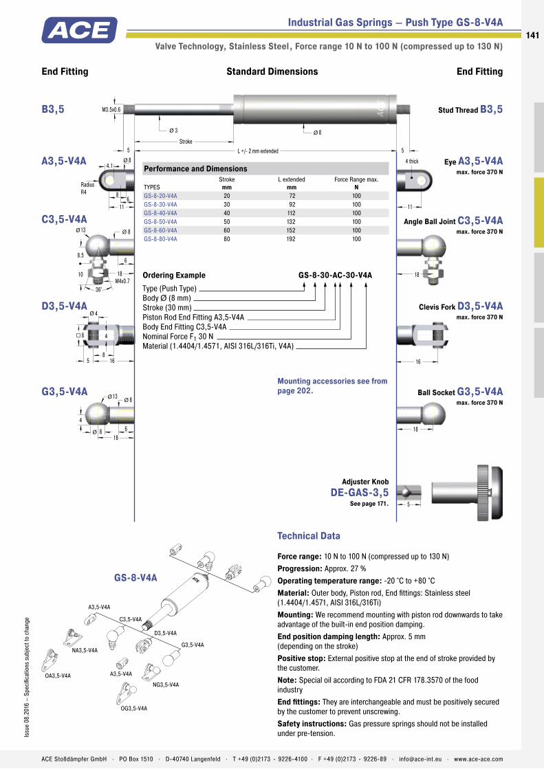
Metering Orifice for Controlled Velocities
Filled with High Pressure Nitrogen Gas
Valve
Oil Zone for End Position Damping
Seals
Stainless Steel Outer Body
Main Bearing
Stainless Steel Piston Rod
Thread for End Fittings
Industrial Gas Springs – Push Type GS-8-V4A
Valve Technology, Stainless Steel , Force range 10 N to 100 N (compressed up to 130 N)
16
4
8
4
5 16
8
Ø
1818
4
13 8
68
18
ØØ
Ø
18M4x0.7
8.5
13 8
6
10
36°
Ø Ø
11
8
11
4.1
6
8Ø
RadiusR4
4 thick
End Fitting End FittingStandard Dimensions
5
M3.5x0.6
5 L +/- 2 mm extended
3
Stroke5
8Ø Ø
A3,5-V4A
C3,5-V4A
NA3,5-V4A
A3,5-V4A
NG3,5-V4A
OG3,5-V4A
OA3,5-V4A
D3,5-V4A
G3,5-V4A
Technical Data
Force range: 10 N to 100 N (compressed up to 130 N)Progression: Approx. 27 %Operating temperature range: -20 °C to +80 °CMaterial: Outer body, Piston rod, End fi ttings: Stainless steel (1.4404/1.4571, AISI 316L/316Ti)Mounting: We recommend mounting with piston rod downwards to take advantage of the built-in end position damping.End position damping length: Approx. 5 mm (depending on the stroke)Positive stop: External positive stop at the end of stroke provided by the customer.Note: Special oil according to FDA 21 CFR 178.3570 of the food industryEnd fi ttings: They are interchangeable and must be positively secured by the customer to prevent unscrewing.Safety instructions: Gas pressure springs should not be installed under pre-tension.
Performance and Dimensions
TYPESStroke
mmL extended
mmForce Range max.
NGS-8-20-V4A 20 72 100GS-8-30-V4A 30 92 100GS-8-40-V4A 40 112 100GS-8-50-V4A 50 132 100GS-8-60-V4A 60 152 100GS-8-80-V4A 80 192 100
Ordering Example GS-8-30-AC-30-V4AType (Push Type)Body Ø (8 mm)Stroke (30 mm)Piston Rod End Fitting A3,5-V4A Body End Fitting C3,5-V4ANominal Force F1 30 NMaterial (1.4404/1.4571, AISI 316L/316Ti, V4A)
GS-8-V4A
Mounting accessories see from page 202.
Stud Thread B3,5 B3,5
Eye A3,5-V4A max. force 370 N
A3,5-V4A
Angle Ball Joint C3,5-V4A max. force 370 N
C3,5-V4A
Clevis Fork D3,5-V4A max. force 370 N
D3,5-V4A
Ball Socket G3,5-V4A max. force 370 N
G3,5-V4A
Adjuster Knob DE-GAS-3,5
See page 171.
141Is
sue
08.2
016
– Sp
ecifi
catio
ns s
ubje
ct to
cha
nge
ACE Stoßdämpfer GmbH . PO Box 1510 . D-40740 Langenfeld . T +49 (0)2173 - 9226-4100 . F +49 (0)2173 - 9226-89 . [email protected] . www.ace-ace.com
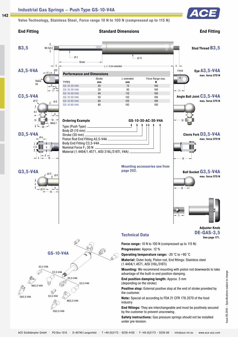
Industrial Gas Springs – Push Type GS-10-V4A
Valve Technology, Stainless Steel , Force range 10 N to 100 N (compressed up to 115 N)
16
4
8
4
5 16
8
Ø
1818
4
13 8
68
18
ØØ
Ø
18M4x0.7
8.5
13 8
6
10
36°
Ø Ø
11
8
11
4.1
6
8Ø
RadiusR4
4 thick
End Fitting End FittingStandard Dimensions
5
M3.5x0.6
5 L +/- 2 mm extended
3
Stroke5
10Ø Ø
A3,5-V4A
C3,5-V4A
NA3,5-V4A
A3,5-V4A
NG3,5-V4A
OG3,5-V4A
OA3,5-V4A
D3,5-V4A
G3,5-V4A
Technical Data
Force range: 10 N to 100 N (compressed up to 115 N)Progression: Approx. 12 %Operating temperature range: -20 °C to +80 °CMaterial: Outer body, Piston rod, End fittings: Stainless steel (1.4404/1.4571, AISI 316L/316Ti)Mounting: We recommend mounting with piston rod downwards to take advantage of the built-in end position damping.End position damping length: Approx. 5 mm (depending on the stroke)Positive stop: External positive stop at the end of stroke provided by the customer.Note: Special oil according to FDA 21 CFR 178.3570 of the food industryEnd fittings: They are interchangeable and must be positively secured by the customer to prevent unscrewing.Safety instructions: Gas pressure springs should not be installed under pre-tension.
Performance and Dimensions
TYPESStroke
mmL extended
mmForce Range max.
NGS-10-20-V4A 20 72 100GS-10-30-V4A 30 92 100GS-10-40-V4A 40 112 100GS-10-50-V4A 50 132 100GS-10-60-V4A 60 152 100GS-10-80-V4A 80 192 100
Ordering Example GS-10-30-AC-30-V4AType (Push Type)Body Ø (10 mm)Stroke (30 mm)Piston Rod End Fitting A3,5-V4A Body End Fitting C3,5-V4ANominal Force F1 30 NMaterial (1.4404/1.4571, AISI 316L/316Ti, V4A)
GS-10-V4A
Mounting accessories see from page 202.
Stud Thread B3,5 B3,5
Eye A3,5-V4A max. force 370 N
A3,5-V4A
Angle Ball Joint C3,5-V4A max. force 370 N
C3,5-V4A
Clevis Fork D3,5-V4A max. force 370 N
D3,5-V4A
Ball Socket G3,5-V4A max. force 370 N
G3,5-V4A
Adjuster Knob DE-GAS-3,5
See page 171.
142
Issu
e 08
.201
6 –
Spec
ifica
tions
sub
ject
to c
hang
e
ACE Stoßdämpfer GmbH . PO Box 1510 . D-40740 Langenfeld . T +49 (0)2173 - 9226-4100 . F +49 (0)2173 - 9226-89 . [email protected] . www.ace-ace.com

Industrial Gas Springs – Push Type GS-12-V4A
Valve Technology, Stainless Steel , Force range 15 N to 180 N (compressed up to 212 N)
16
4
8
4
5 16
8
Ø
1818
4
13 8
68
18
ØØ
Ø
18M4x0.7
8.5
13 8
6
10
36°
Ø Ø
11
8
11
4.1
6
8Ø
RadiusR4
4 thick
End Fitting End FittingStandard Dimensions
5
M3.5x0.6
5 L +/- 2 mm extended
4
Stroke5
12Ø Ø
A3,5-V4A
C3,5-V4A
NA3,5-V4A
A3,5-V4A
NG3,5-V4A
OG3,5-V4A
OA3,5-V4A
D3,5-V4A
G3,5-V4A
Technical Data
Force range: 15 N to 180 N (compressed up to 212 N)Progression: Approx. 18 %Operating temperature range: -20 °C to +80 °CMaterial: Outer body, Piston rod, End fittings: Stainless steel (1.4404/1.4571, AISI 316L/316Ti)Mounting: We recommend mounting with piston rod downwards to take advantage of the built-in end position damping.End position damping length: Approx. 10 mm (depending on the stroke)Positive stop: External positive stop at the end of stroke provided by the customer.Note: Special oil according to FDA 21 CFR 178.3570 of the food industryEnd fittings: They are interchangeable and must be positively secured by the customer to prevent unscrewing.Safety instructions: Gas pressure springs should not be installed under pre-tension.
Performance and Dimensions
TYPESStroke
mmL extended
mmForce Range max.
NGS-12-20-V4A 20 72 180GS-12-30-V4A 30 92 180GS-12-40-V4A 40 112 180GS-12-50-V4A 50 132 180GS-12-60-V4A 60 152 180GS-12-80-V4A 80 192 150GS-12-100-V4A 100 232 150GS-12-120-V4A 120 272 120GS-12-150-V4A 150 332 100
Ordering Example GS-12-100-AA-30-V4AType (Push Type)Body Ø (12 mm)Stroke (100 mm)Piston Rod End Fitting A3,5-V4A Body End Fitting A3,5-V4ANominal Force F1 30 NMaterial (1.4404/1.4571, AISI 316L/316Ti, V4A)
GS-12-V4A
Mounting accessories see from page 202.
Stud Thread B3,5 B3,5
Eye A3,5-V4A max. force 370 N
A3,5-V4A
Angle Ball Joint C3,5-V4A max. force 370 N
C3,5-V4A
Clevis Fork D3,5-V4A max. force 370 N
D3,5-V4A
Ball Socket G3,5-V4A max. force 370 N
G3,5-V4A
Adjuster Knob DE-GAS-3,5
See page 171.
143Is
sue
08.2
016
– Sp
ecifi
catio
ns s
ubje
ct to
cha
nge
ACE Stoßdämpfer GmbH . PO Box 1510 . D-40740 Langenfeld . T +49 (0)2173 - 9226-4100 . F +49 (0)2173 - 9226-89 . [email protected] . www.ace-ace.com

Industrial Gas Springs – Push Type GS-15-VA
Valve Technology, Stainless Steel , Force range 40 N to 400 N (compressed up to 535 N)
End Fitting End FittingStandard Dimensions
7
2222
4.5
13 8
128
M5x0.8
22
7 L+/- 2 mm extended
6
Stroke7
15.6
L = Stroke + 20
19
ØØ
Ø
Ø Ø
27
Ø
22M5x0.8
8
13 8
12
10
36°
Ø Ø
20
16
24° 10 5
8
12
13
4.5
10 2712
ØØ
Ø
5
10
5
6 20
10
Ø
14
9
16
6.1
8
10Ø
RadiusR5
6 thick
A5-VA
MA5-V4A
NG5-V4A
NA5-V4A
OG5-V4A
OA5-V4A
PA5-V4A
PG5-V4A
C5-VAD5-VA
E5-VAG5-VA
Technical Data
Force range: 40 N to 400 N (compressed up to 535 N)Progression: Approx. 34 %Operating temperature range: -20 °C to +80 °CMaterial: Outer body, Piston rod, End fittings: Stainless steel (1.4301/1.4305, AISI 304/303)Mounting: We recommend mounting with piston rod downwards to take advantage of the built-in end position damping.End position damping length: Approx. 20 mm (depending on the stroke)Positive stop: External positive stop at the end of stroke provided by the customer.Note: Special oil according to FDA 21 CFR 178.3570 of the food industryEnd fittings: They are interchangeable and must be positively secured by the customer to prevent unscrewing.Safety instructions: Gas pressure springs should not be installed under pre-tension.
Performance and Dimensions
TYPESStroke
mmL extended
mmForce Range max.
NGS-15-20-VA 20 74 400GS-15-40-VA 40 114 400GS-15-50-VA 50 134 400GS-15-60-VA 60 154 400GS-15-80-VA 80 194 400GS-15-100-VA 100 234 400GS-15-120-VA 120 274 400GS-15-150-VA 150 334 400
Ordering Example GS-15-150-AC-150-VAType (Push Type)Body Ø (15.6 mm)Stroke (150 mm)Piston Rod End Fitting A5-VABody End Fitting C5-VANominal Force F1 150 NMaterial (1.4301/1.4305, AISI 304/303, VA)
GS-15-VA
Mounting accessories see from page 202.
Stud Thread B5 B5
Eye A5-VA max. force 490 N
A5-VA
Angle Ball Joint C5-VA max. force 430 N
C5-VA
Clevis Fork D5-VA max. force 490 N
D5-VA
Swivel Eye E5-VA max. force 490 N
E5-VA
Ball Socket G5-VA max. force 430 N
G5-VA
Rod Shroud W5-15-VA
Adjuster Knob DE-GAS-5
See page 171.
144
Issu
e 08
.201
6 –
Spec
ifica
tions
sub
ject
to c
hang
e
ACE Stoßdämpfer GmbH . PO Box 1510 . D-40740 Langenfeld . T +49 (0)2173 - 9226-4100 . F +49 (0)2173 - 9226-89 . [email protected] . www.ace-ace.com

Industrial Gas Springs – Push Type GS-19-VA
Valve Technology, Stainless Steel , Force range 50 N to 700 N (compressed up to 930 N)
End Fitting End FittingStandard Dimensions
10
3030
6
20 13
1513
M8x1.25
30
10 L+/- 2 mm extended
8
Stroke10
19
L = Stroke + 30
23
ØØ
Ø
Ø Ø
36
Ø
30M8x1.25
12
20 13
15
16,5
36°
Ø Ø
32
19
24° 12 8
12
16
16
6
12 3613
ØØ
Ø
8
16
8
10 32
16
Ø
22
11.5
19
8.1
10
14Ø
RadiusR7
10 thick
A8-VA
MA8-V4A
MA8-V4A
NG8-V4A
NA8-V4A
OG8-V4A
OA8-V4A
PA8-V4A
PG8-V4A
C8-VAD8-VA
E8-VAG8-VA
Technical Data
Force range: 50 N to 700 N (compressed up to 930 N)Progression: Approx. 33 %Operating temperature range: -20 °C to +80 °CMaterial: Outer body, Piston rod, End fittings: Stainless steel (1.4301/1.4305, AISI 304/303)Mounting: We recommend mounting with piston rod downwards to take advantage of the built-in end position damping.End position damping length: Approx. 20 mm (depending on the stroke)Positive stop: External positive stop at the end of stroke provided by the customer.Note: Special oil according to FDA 21 CFR 178.3570 of the food industryEnd fittings: They are interchangeable and must be positively secured by the customer to prevent unscrewing.Safety instructions: Gas pressure springs should not be installed under pre-tension.
Performance and Dimensions
TYPESStroke
mmL extended
mmForce Range max.
NGS-19-50-VA 50 164 700GS-19-100-VA 100 264 700GS-19-150-VA 150 364 700GS-19-200-VA 200 464 700GS-19-250-VA 250 564 700GS-19-300-VA 300 664 700
Ordering Example GS-19-150-AC-600-VAType (Push Type)Body Ø (19 mm)Stroke (150 mm)Piston Rod End Fitting A8-VABody End Fitting C8-VANominal Force F1 600 NMaterial (1.4301/1.4305, AISI 304/303, VA)
GS-19-VA
Mounting accessories see from page 202.
Stud Thread B8 B8
Eye A8-VA max. force 1,560 N
A8-VA
Angle Ball Joint C8-VA max. force 1,140 N
C8-VA
Clevis Fork D8-VA max. force 1,560 N
D8-VA
Swivel Eye E8-VA max. force 1,560 N
E8-VA
Ball Socket G8-VA max. force 1,140 N
G8-VA
Rod Shroud W8-19-VA
Adjuster Knob DE-GAS-8
See page 171.
145Is
sue
08.2
016
– Sp
ecifi
catio
ns s
ubje
ct to
cha
nge
ACE Stoßdämpfer GmbH . PO Box 1510 . D-40740 Langenfeld . T +49 (0)2173 - 9226-4100 . F +49 (0)2173 - 9226-89 . [email protected] . www.ace-ace.com
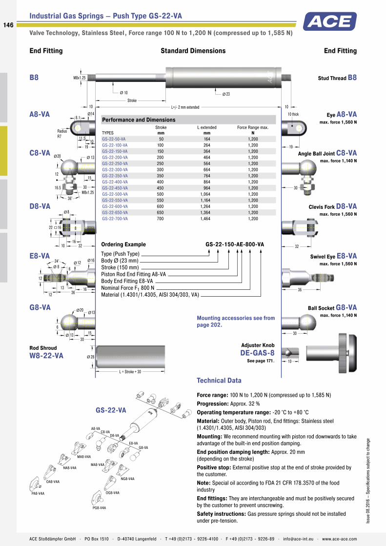
Industrial Gas Springs – Push Type GS-22-VA
Valve Technology, Stainless Steel , Force range 100 N to 1,200 N (compressed up to 1,585 N)
End Fitting End FittingStandard Dimensions
10
3030
6
20 13
1513
M8x1.25
30
10 L+/- 2 mm extended
10
Stroke10
23
L = Stroke + 30
28
ØØ
Ø
Ø Ø
36
Ø
30M8x1.25
12
20 13
15
16.5
36°
Ø Ø
32
19
24° 12 8
12
16
16
6
12 3613
ØØ
Ø
8
16
8
10 32
16
Ø
22
11.5
19
8.1
10
14Ø
RadiusR7
10 thick
A8-VA
MA8-V4A
MA8-V4A
NG8-V4A
NA8-V4A
OG8-V4A
OA8-V4A
PA8-V4A
PG8-V4A
C8-VAD8-VA
E8-VAG8-VA
Technical Data
Force range: 100 N to 1,200 N (compressed up to 1,585 N)Progression: Approx. 32 %Operating temperature range: -20 °C to +80 °CMaterial: Outer body, Piston rod, End fittings: Stainless steel (1.4301/1.4305, AISI 304/303)Mounting: We recommend mounting with piston rod downwards to take advantage of the built-in end position damping.End position damping length: Approx. 20 mm (depending on the stroke)Positive stop: External positive stop at the end of stroke provided by the customer.Note: Special oil according to FDA 21 CFR 178.3570 of the food industryEnd fittings: They are interchangeable and must be positively secured by the customer to prevent unscrewing.Safety instructions: Gas pressure springs should not be installed under pre-tension.
Performance and Dimensions
TYPESStroke
mmL extended
mmForce Range max.
NGS-22-50-VA 50 164 1,200GS-22-100-VA 100 264 1,200GS-22-150-VA 150 364 1,200GS-22-200-VA 200 464 1,200GS-22-250-VA 250 564 1,200GS-22-300-VA 300 664 1,200GS-22-350-VA 350 764 1,200GS-22-400-VA 400 864 1,200GS-22-450-VA 450 964 1,200GS-22-500-VA 500 1,064 1,200GS-22-550-VA 550 1,164 1,200GS-22-600-VA 600 1,264 1,200GS-22-650-VA 650 1,364 1,200GS-22-700-VA 700 1,464 1,200
Ordering Example GS-22-150-AE-800-VAType (Push Type)Body Ø (23 mm)Stroke (150 mm)Piston Rod End Fitting A8-VABody End Fitting E8-VANominal Force F1 800 NMaterial (1.4301/1.4305, AISI 304/303, VA)
GS-22-VA
Mounting accessories see from page 202.
Stud Thread B8 B8
Eye A8-VA max. force 1,560 N
A8-VA
Angle Ball Joint C8-VA max. force 1,140 N
C8-VA
Clevis Fork D8-VA max. force 1,560 N
D8-VA
Swivel Eye E8-VA max. force 1,560 N
E8-VA
Ball Socket G8-VA max. force 1,140 N
G8-VA
Rod Shroud W8-22-VA
Adjuster Knob DE-GAS-8
See page 171.
146
Issu
e 08
.201
6 –
Spec
ifica
tions
sub
ject
to c
hang
e
ACE Stoßdämpfer GmbH . PO Box 1510 . D-40740 Langenfeld . T +49 (0)2173 - 9226-4100 . F +49 (0)2173 - 9226-89 . [email protected] . www.ace-ace.com

Industrial Gas Springs – Push Type GS-28-VA
Valve Technology, Stainless Steel , Force range 150 N to 2,500 N (compressed up to 3,800 N)
End Fitting End FittingStandard Dimensions
12
M10x1.5
35
12 L+/- 2 mm extended
14
Stroke12
28
L = Stroke + 40
32
Ø Ø
43
Ø
35M10x1.5
16
24 16
18
20
36°
Ø Ø
40
27
24° 15 10
14
18
19
7
14 4316
ØØ
Ø
10
20
10
12 40
20
Ø
26.5
15
27
8.1
15
18Ø
RadiusR9
10 thick
A10-VAC10-VA
D10-VAE10-VA
MA10-V4A
Technical Data
Force range: 150 N to 2,500 N (compressed up to 3,800 N)Progression: Approx. 52 %Operating temperature range: -20 °C to +80 °CMaterial: Outer body, Piston rod, End fittings: Stainless steel (1.4301/1.4305, AISI 304/303)Mounting: We recommend mounting with piston rod downwards to take advantage of the built-in end position damping.End position damping length: Approx. 20 mm (depending on the stroke)Positive stop: External positive stop at the end of stroke provided by the customer.Note: Special oil according to FDA 21 CFR 178.3570 of the food industryEnd fittings: They are interchangeable and must be positively secured by the customer to prevent unscrewing.Safety instructions: Gas pressure springs should not be installed under pre-tension.
Performance and Dimensions
TYPESStroke
mmL extended
mmForce Range max.
NGS-28-100-VA 100 262 2,500GS-28-150-VA 150 362 2,500GS-28-200-VA 200 462 2,500GS-28-250-VA 250 562 2,500GS-28-300-VA 300 662 2,500GS-28-350-VA 350 762 2,500GS-28-400-VA 400 862 2,500GS-28-450-VA 450 962 2,500GS-28-500-VA 500 1,062 2,500GS-28-550-VA 550 1,162 2,500GS-28-600-VA 600 1,262 2,500GS-28-650-VA 650 1,362 2,500
Ordering Example GS-28-150-EE-1200-VAType (Push Type)Body Ø (28 mm)Stroke (150 mm)Piston Rod End Fitting E10-VABody End Fitting E10-VANominal Force F1 1200 NMaterial (1.4301/1.4305, AISI 304/303, VA)
GS-28-VA
Mounting accessories see from page 202.
Stud Thread B10 B10
Eye A10-VA max. force 3,800 N
A10-VA
Angle Ball Joint C10-VA max. force 1,750 N
C10-VA
Clevis Fork D10-VA max. force 3,800 N
D10-VA
Swivel Eye E10-VA max. force 3,800 N
E10-VA
Rod Shroud W10-28-VA
Adjuster Knob DE-GAS-10
See page 171.
147Is
sue
08.2
016
– Sp
ecifi
catio
ns s
ubje
ct to
cha
nge
ACE Stoßdämpfer GmbH . PO Box 1510 . D-40740 Langenfeld . T +49 (0)2173 - 9226-4100 . F +49 (0)2173 - 9226-89 . [email protected] . www.ace-ace.com

Industrial Gas Springs – Push Type GS-40-VA
Valve Technology, Stainless Steel , Force range 500 N to 5,000 N (compressed up to 7,000 N)
End Fitting End FittingStandard Dimensions
15
M14x1.5
45
15 L +/- 2 mm extended
20Stroke
15
40
L = Stroke + 40
45
Ø Ø
57
Ø
45M14x1.5
20
30 22
25
28
36°
Ø Ø
56
42
30° 20 14
19
30
26
13
18 5718
ØØ
Ø
14
27
14
16 56
27
Ø
35
19.5
42
14.1
20
25Ø
RadiusR12.5
14 thick
A14-VAC14-VA
D14-VAE14-VA
ME14-VA
ME14-VA
ND14-VA
Technical Data
Force range: 500 N to 5,000 N (compressed up to 7,000 N)Progression: Approx. 40 %Operating temperature range: -20 °C to +80 °CMaterial: Outer body, Piston rod, End fittings: Stainless steel (1.4301/1.4305, AISI 304/303)Mounting: We recommend mounting with piston rod downwards to take advantage of the built-in end position damping.End position damping length: Approx. 30 mm (depending on the stroke)Positive stop: External positive stop at the end of stroke provided by the customer.Note: Special oil according to FDA 21 CFR 178.3570 of the food industryEnd fittings: They are interchangeable and must be positively secured by the customer to prevent unscrewing.Safety instructions: Gas pressure springs should not be installed under pre-tension.
Performance and Dimensions
TYPESStroke
mmL extended
mmForce Range max.
NGS-40-100-VA 100 317 5,000GS-40-150-VA 150 417 5,000GS-40-200-VA 200 517 5,000GS-40-300-VA 300 717 5,000GS-40-400-VA 400 917 5,000GS-40-500-VA 500 1,117 5,000GS-40-600-VA 600 1,317 5,000
Ordering Example GS-40-150-DD-3500-VAType (Push Type)Body Ø (40 mm)Stroke (150 mm)Piston Rod End Fitting D14-VABody End Fitting D14-VANominal Force F1 3500 NMaterial (1.4301/1.4305, AISI 304/303, VA)
GS-40-VA
Mounting accessories see from page 202.
Stud Thread B14 B14
Eye A14-VA max. force 7,000 N
A14-VA
Angle Ball Joint C14-VA max. force 3,200 N
C14-VA
Clevis Fork D14-VA max. force 7,000 N
D14-VA
Swivel Eye E14-VA max. force 7,000 N
E14-VA
Rod Shroud W14-40-VA
Adjuster Knob DE-GAS-14
See page 171.
148
Issu
e 08
.201
6 –
Spec
ifica
tions
sub
ject
to c
hang
e
ACE Stoßdämpfer GmbH . PO Box 1510 . D-40740 Langenfeld . T +49 (0)2173 - 9226-4100 . F +49 (0)2173 - 9226-89 . [email protected] . www.ace-ace.com
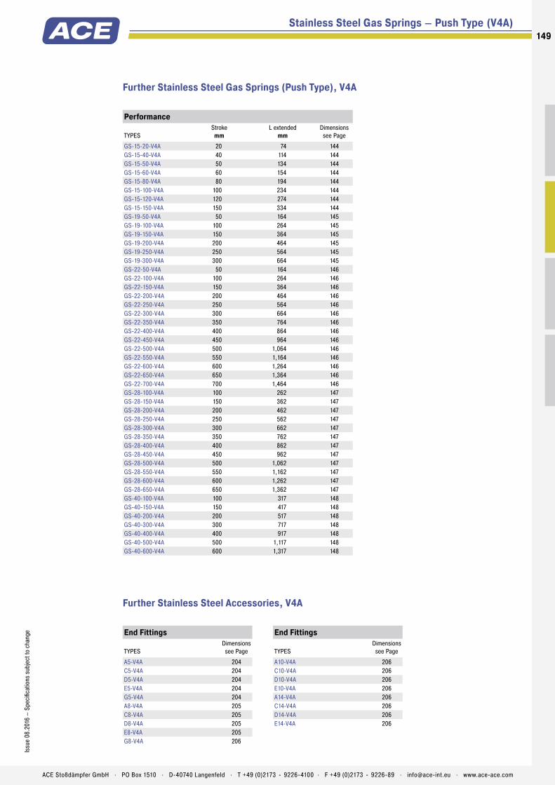
Stainless Steel Gas Springs – Push Type (V4A)
Performance
TYPESStroke
mmL extended
mmDimensions see Page
GS-15-20-V4A 20 74 144GS-15-40-V4A 40 114 144GS-15-50-V4A 50 134 144GS-15-60-V4A 60 154 144GS-15-80-V4A 80 194 144GS-15-100-V4A 100 234 144GS-15-120-V4A 120 274 144GS-15-150-V4A 150 334 144GS-19-50-V4A 50 164 145GS-19-100-V4A 100 264 145GS-19-150-V4A 150 364 145GS-19-200-V4A 200 464 145GS-19-250-V4A 250 564 145GS-19-300-V4A 300 664 145GS-22-50-V4A 50 164 146GS-22-100-V4A 100 264 146GS-22-150-V4A 150 364 146GS-22-200-V4A 200 464 146GS-22-250-V4A 250 564 146GS-22-300-V4A 300 664 146GS-22-350-V4A 350 764 146GS-22-400-V4A 400 864 146GS-22-450-V4A 450 964 146GS-22-500-V4A 500 1,064 146GS-22-550-V4A 550 1,164 146GS-22-600-V4A 600 1,264 146GS-22-650-V4A 650 1,364 146GS-22-700-V4A 700 1,464 146GS-28-100-V4A 100 262 147GS-28-150-V4A 150 362 147GS-28-200-V4A 200 462 147GS-28-250-V4A 250 562 147GS-28-300-V4A 300 662 147GS-28-350-V4A 350 762 147GS-28-400-V4A 400 862 147GS-28-450-V4A 450 962 147GS-28-500-V4A 500 1,062 147GS-28-550-V4A 550 1,162 147GS-28-600-V4A 600 1,262 147GS-28-650-V4A 650 1,362 147GS-40-100-V4A 100 317 148GS-40-150-V4A 150 417 148GS-40-200-V4A 200 517 148GS-40-300-V4A 300 717 148GS-40-400-V4A 400 917 148GS-40-500-V4A 500 1,117 148GS-40-600-V4A 600 1,317 148
Further Stainless Steel Gas Springs (Push Type), V4A
Further Stainless Steel Accessories, V4A
End Fittings
TYPESDimensions see Page
A5-V4A 204C5-V4A 204D5-V4A 204E5-V4A 204G5-V4A 204A8-V4A 205C8-V4A 205D8-V4A 205E8-V4A 205G8-V4A 206
End Fittings
TYPESDimensions see Page
A10-V4A 206C10-V4A 206D10-V4A 206E10-V4A 206A14-V4A 206C14-V4A 206D14-V4A 206E14-V4A 206
149Is
sue
08.2
016
– Sp
ecifi
catio
ns s
ubje
ct to
cha
nge
ACE Stoßdämpfer GmbH . PO Box 1510 . D-40740 Langenfeld . T +49 (0)2173 - 9226-4100 . F +49 (0)2173 - 9226-89 . [email protected] . www.ace-ace.com
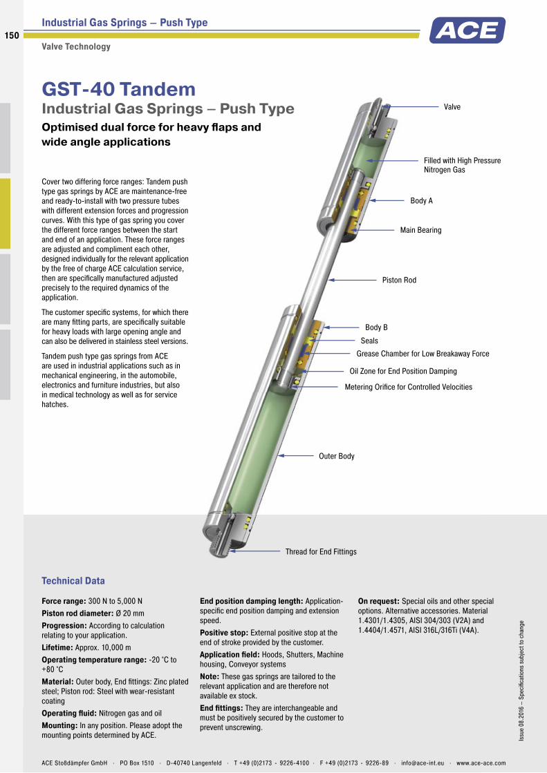
Metering Orifice for Controlled Velocities
Filled with High Pressure Nitrogen Gas
Valve
Oil Zone for End Position Damping
Seals
Piston Rod
Main Bearing
Outer Body
Thread for End Fittings
Grease Chamber for Low Breakaway Force
Body A
Body B
Technical Data
Cover two differing force ranges: Tandem push type gas springs by ACE are maintenance-free and ready-to-install with two pressure tubes with different extension forces and progression curves. With this type of gas spring you cover the different force ranges between the start and end of an application. These force ranges are adjusted and compliment each other, designed individually for the relevant application by the free of charge ACE calculation service, then are specifi cally manufactured adjusted precisely to the required dynamics of the application.
The customer specifi c systems, for which there are many fi tting parts, are specifi cally suitable for heavy loads with large opening angle and can also be delivered in stainless steel versions.
Tandem push type gas springs from ACE are used in industrial applications such as in mechanical engineering, in the automobile, electronics and furniture industries, but also in medical technology as well as for service hatches.
GST-40 TandemIndustrial Gas Springs – Push Type Optimised dual force for heavy fl aps and wide angle applications
Industrial Gas Springs – Push Type
Valve Technology
Force range: 300 N to 5,000 NPiston rod diameter: Ø 20 mmProgression: According to calculation relating to your application.Lifetime: Approx. 10,000 mOperating temperature range: -20 °C to +80 °CMaterial: Outer body, End fi ttings: Zinc plated steel; Piston rod: Steel with wear-resistant coatingOperating fl uid: Nitrogen gas and oilMounting: In any position. Please adopt the mounting points determined by ACE.
End position damping length: Application-specifi c end position damping and extension speed.Positive stop: External positive stop at the end of stroke provided by the customer.Application fi eld: Hoods, Shutters, Machine housing, Conveyor systemsNote: These gas springs are tailored to the relevant application and are therefore not available ex stock.End fi ttings: They are interchangeable and must be positively secured by the customer to prevent unscrewing.
On request: Special oils and other special options. Alternative accessories. Material 1.4301/1.4305, AISI 304/303 (V2A) and 1.4404/1.4571, AISI 316L/316Ti (V4A).
150
Issu
e 08
.201
6 –
Spec
ifi ca
tions
sub
ject
to c
hang
e
ACE Stoßdämpfer GmbH . PO Box 1510 . D-40740 Langenfeld . T +49 (0)2173 - 9226-4100 . F +49 (0)2173 - 9226-89 . [email protected] . www.ace-ace.com

Metering Orifice for Controlled Velocities
Filled with High Pressure Nitrogen Gas
Valve
Oil Zone for End Position Damping
Seals
Piston Rod
Main Bearing
Outer Body
Thread for End Fittings
Grease Chamber for Low Breakaway Force
Body A
Body B
Industrial Gas Springs – Push Type GST-40
Valve Technology , Force range 300 N to 5,000 N
End Fitting End FittingStandard Dimensions
56
14
27
14
16 56
27
15
M14x1.5
25
21
40 L +/- 2 mm extended
14.1
RadiusR12.5
14 thick
40
14 thick
21
Ø
Ø
57
Ø Ø
15
14.1
30° 20 14
19
30
26
13
18 5718
ØØØ
Body AØ 40
Body BØ 40 Stroke BStroke A
20Ø
A14
ME14
D14
E14
ND14
ME14
Technical Data
Progression: According to calculation relating to your application.Operating temperature range: -20 °C to +80 °CMaterial: Outer body, End fi ttings: Zinc plated steel; Piston rod: Steel with wear-resistant coatingMounting: In any position. Please adopt the mounting points deter-mined by ACE.End position damping length: Application-specifi c end position damping and extension speed.Positive stop: External positive stop at the end of stroke provided by the customer.Note: These gas springs are tailored to the relevant application and are therefore not available ex stock.End fi ttings: They are interchangeable and must be positively secured by the customer to prevent unscrewing.
Performance and Dimensions
TYPESStroke A
mmStroke B
mmL extended
mmForce Range max.
NGST-40-50-100 50 100 485 5,000GST-40-50-150 50 150 585 5,000GST-40-50-200 50 200 685 5,000GST-40-70-250 70 250 825 5,000GST-40-70-300 70 300 925 5,000GST-40-70-350 70 350 1,025 5,000GST-40-70-400 70 400 1,125 5,000
Ordering Example GST-40-50-150-AD-900N-2500NType (Tandem Gas Spring)Body Ø (40 mm)Stroke A (50 mm)Stroke B (150 mm)Body A End Fitting, A14Body B End Fitting, D14Nominal Force Body A, 900 NNominal Force Body B, 2500 N
GST-40
Mounting accessories see from page 194.
Eye A14 max. force 10,000 N
A14
Stud Thread B14 B14
Clevis Fork D14 max. force 10,000 N
D14
Swivel Eye E14 max. force 10,000 N
E14
151Is
sue
08.2
016
– Sp
ecifi
catio
ns s
ubje
ct to
cha
nge
ACE Stoßdämpfer GmbH . PO Box 1510 . D-40740 Langenfeld . T +49 (0)2173 - 9226-4100 . F +49 (0)2173 - 9226-89 . [email protected] . www.ace-ace.com
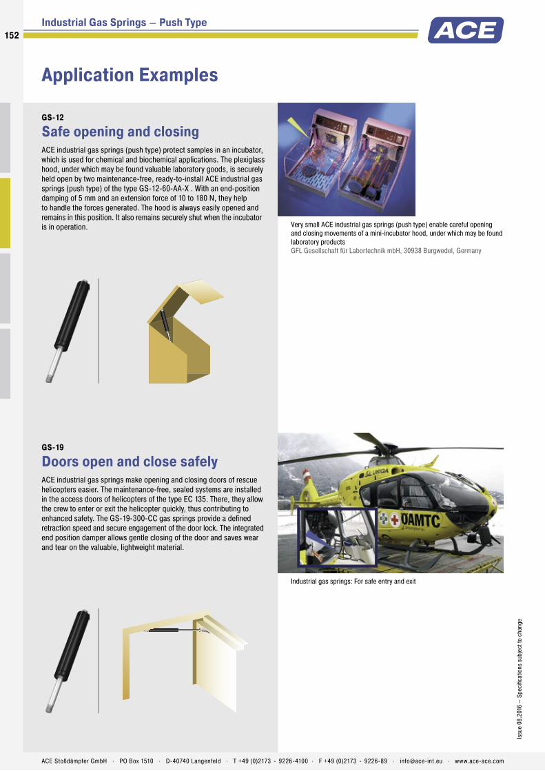
Application Examples
Industrial Gas Springs – Push Type
GS-12
Safe opening and closingACE industrial gas springs (push type) protect samples in an incubator, which is used for chemical and biochemical applications. The plexiglass hood, under which may be found valuable laboratory goods, is securely held open by two maintenance-free, ready-to-install ACE industrial gas springs (push type) of the type GS-12-60-AA-X . With an end-position damping of 5 mm and an extension force of 10 to 180 N, they help to handle the forces generated. The hood is always easily opened and remains in this position. It also remains securely shut when the incubator is in operation.
Very small ACE industrial gas springs (push type) enable careful opening and closing movements of a mini-incubator hood, under which may be found laboratory products GFL Gesellschaft für Labortechnik mbH, 30938 Burgwedel, Germany
GS-19
Doors open and close safelyACE industrial gas springs make opening and closing doors of rescue helicopters easier. The maintenance-free, sealed systems are installed in the access doors of helicopters of the type EC 135. There, they allow the crew to enter or exit the helicopter quickly, thus contributing to enhanced safety. The GS-19-300-CC gas springs provide a defi ned retraction speed and secure engagement of the door lock. The integrated end position damper allows gentle closing of the door and saves wear and tear on the valuable, lightweight material.
Industrial gas springs: For safe entry and exit
152
Issu
e 08
.201
6 –
Spec
ifi ca
tions
sub
ject
to c
hang
e
ACE Stoßdämpfer GmbH . PO Box 1510 . D-40740 Langenfeld . T +49 (0)2173 - 9226-4100 . F +49 (0)2173 - 9226-89 . [email protected] . www.ace-ace.com
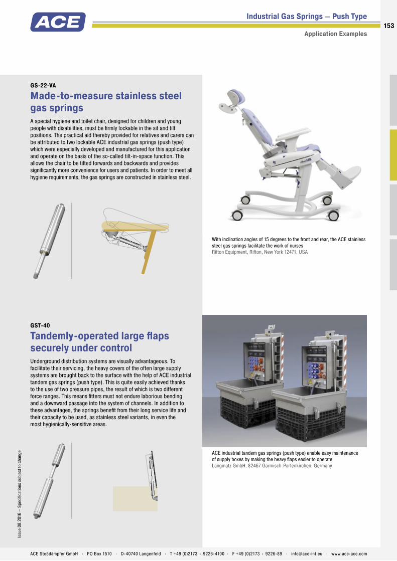
Industrial Gas Springs – Push Type
Application Examples
GS-22-VA
Made-to-measure stainless steel gas springsA special hygiene and toilet chair, designed for children and young people with disabilities, must be fi rmly lockable in the sit and tilt positions. The practical aid thereby provided for relatives and carers can be attributed to two lockable ACE industrial gas springs (push type) which were especially developed and manufactured for this application and operate on the basis of the so-called tilt-in-space function. This allows the chair to be tilted forwards and backwards and provides signifi cantly more convenience for users and patients. In order to meet all hygiene requirements, the gas springs are constructed in stainless steel.
With inclination angles of 15 degrees to the front and rear, the ACE stainless steel gas springs facilitate the work of nurses Rifton Equipment, Rifton, New York 12471, USA
GST-40
Tandemly-operated large fl aps securely under controlUnderground distribution systems are visually advantageous. To facilitate their servicing, the heavy covers of the often large supply systems are brought back to the surface with the help of ACE industrial tandem gas springs (push type). This is quite easily achieved thanks to the use of two pressure pipes, the result of which is two different force ranges. This means fi tters must not endure laborious bending and a downward passage into the system of channels. In addition to these advantages, the springs benefi t from their long service life and their capacity to be used, as stainless steel variants, in even the most hygienically-sensitive areas.
ACE industrial tandem gas springs (push type) enable easy maintenance of supply boxes by making the heavy fl aps easier to operate Langmatz GmbH, 82467 Garmisch-Partenkirchen, Germany
153Is
sue
08.2
016
– Sp
ecifi
catio
ns s
ubje
ct to
cha
nge
ACE Stoßdämpfer GmbH . PO Box 1510 . D-40740 Langenfeld . T +49 (0)2173 - 9226-4100 . F +49 (0)2173 - 9226-89 . [email protected] . www.ace-ace.com

Industrial Gas Springs – Pull TypeTakes over when things get too tight for gas pressure springs
If ACE gas push type springs cannot be used due to a lack of space, ACE’s industrial gas pull type springs come into their own. The compact assistants with body diameters of 15 to 40 mm are effective in the direction of traction and work in the opposite way to the principle of gas push type springs.
This means that the gas pressure in the cylinder draws the piston rod in and, when closing a fl ap for example, supports the manual force with the pressure springs. ACE‘s gas pull type springs are also self-contained, maintenance-free machine elements and equipped with a standard valve to individually regulate the gas pressure, whereby they cover forces between 30 and 5,000 N. Any installation position, extensive DIN standardised accessories and various models enable universal use.
Motion Control
Compact design
Individual fi lling valve technology
Calculation program for specifi c design
Universally applicable
Delivery time within 24 hours
154154
ACE Stoßdämpfer GmbH . PO Box 1510 . D-40740 Langenfeld . T +49 (0)2173 - 9226-4100 . [email protected] . www.ace-ace.com

55Total Stroke mm
F2FR
F1
F3
F4 Outward Stroke
Inward Stroke
Gas Springs (Pull Type)Type Progression
approx. %1 Friction FR
approx. in NGZ-15 23 55 - 140GZ-19 10 20 - 40GZ-28 20 100 - 200GZ-40 40
1 Depending on the fi lling force 2 Depending on the stroke
Product Families
Overview
Industrial Gas Springs – Pull Type
GZ-15 to GZ-40 Valve Technology Very low progression rateHoods, Shutters, Machine housing, Conveyor systems
Page 156
GZ-15-V4A to GZ-40-VA Valve Technology, Stainless Steel Very low progression rate with FDA approvalHoods, Shutters, Machine housing, Conveyor systems
Page 162
Compact design
Individual fi lling valve technology
Calculation program for specifi c design
Universally applicable
Delivery time within 24 hours
F1 = nominal force at 20 °C (this is the pressure fi gure normally used when specifying the gas spring)
F2 = force in the complete extended position When extending the piston rod, there is an additional friction force caused by the contact pressure of the seals (this only occurs during the extension stroke): F3 = force at the beginning of the extension stroke F4 = force at the end of the extension stroke
Calculation Principles Force-Stroke Characteristics of Traction Gas Spring (Pull Type)
Gas pull type springs work based on the reverse principle of a gas push type spring. They are also individually fi lled according to customer request to a certain pressure (extension force F1). However, the piston rod here is pulled inwards by the gas pressure in the cylinder. The higher the pressure, the greater the extension force. The piston ring surface between the piston rod and the inner tube is decisive for the function. When the piston rod pulls out, the nitrogen from the piston is compressed in the inner tube. The force increase (progression) of the gas spring is due to the rising pressure. The force increase is almost linear.
Function of a Gas Spring – Pull Type
Progression: (the slope of the force line in the diagram above) is due to the reduction of the internal gas volume as the piston rod moves from its initial position to its fully stroked position. The approx. progression values given above for standard springs can be altered on request. Effect of termperature: The nominal F1 fi gure is given at 20 °C. An increase of 10 °C will increase force by 3.4 %. Filling tolerances: 20 N to +40 N or 5 % to 7 %. Depending on size and extension force the tolerances can differ.
Free calculation service see page 168!
155Is
sue
08.2
016
– Sp
ecifi
catio
ns s
ubje
ct to
cha
nge
ACE Stoßdämpfer GmbH . PO Box 1510 . D-40740 Langenfeld . T +49 (0)2173 - 9226-4100 . F +49 (0)2173 - 9226-89 . [email protected] . www.ace-ace.com

Filled with High Pressure Nitrogen Gas
Valve
Seals
Outer Body
Main Bearing
Piston Rod
Thread for End Fittings
Piston with Seals
Technical Data
The solution to a lack of space: If standard push type gas springs cannot be used due to a lack of space, ACES‘ industrial pull type gas springs come into their own. They work in the opposite way to standard push type gas springs. The piston rod is retracted when the cylinder is unloaded. The gas pressure in the cylinder draws the piston rod in.
ACE pull type gas springs offer the maximum service life thanks to the solid chrome-plated piston rod and an integrated sliding bearing. The maintenance-free and ready-to-install products are available in body diameters of 15 to 40 mm as well as forces from 40 to 5,000 N and are available from stock with valve and large selection of accessories. The traction force can be subsequently adjusted using the valve.
Gas traction springs from ACE are used in industrial applications, especially in mechani-cal engineering and in medical technology as well as in the electronics and furniture industries.
GZ-15 to GZ-40Industrial Gas Springs – Pull Type Very low progression rate
Industrial Gas Springs – Pull Type
Valve Technology
Traction force range: 40 N to 5,000 NPiston rod diameter: Ø 4 mm bis Ø 28 mmProgression: Approx. 20 % bis 40 %Lifetime: Approx. 2,000 mOperating temperature range: -20 °C to +80 °CMaterial: Outer body, End fi ttings: Zinc plated steel; Piston rod: Steel or stainless steel with wear-resistant coatingOperating fl uid: Nitrogen gasMounting: With piston rod upwards.
End position damping length: Without damping. For end position damping use damping material (e.g. TUBUS or SLAB).Positive stop: External positive stop at the end of stroke provided by the customer.Application fi eld: Hoods, Shutters, Machine housing, Conveyor systemsEnd fi ttings: They are interchangeable and must be positively secured by the customer to prevent unscrewing.On request: Special oils and other special options. Alternative accessories. Traction gas
springs with end position damping also available on request.
156
Issu
e 08
.201
6 –
Spec
ifi ca
tions
sub
ject
to c
hang
e
ACE Stoßdämpfer GmbH . PO Box 1510 . D-40740 Langenfeld . T +49 (0)2173 - 9226-4100 . F +49 (0)2173 - 9226-89 . [email protected] . www.ace-ace.com

Filled with High Pressure Nitrogen Gas
Valve
Seals
Outer Body
Main Bearing
Piston Rod
Thread for End Fittings
Piston with Seals
Industrial Gas Springs – Pull Type GZ-15
Valve Technology , Traction force range 50 N to 150 N (extended up to 185 N)
End Fitting End FittingStandard Dimensions
5
24° 7.8 4
5
5.3
7 127.3
ØØ
7
1818
4
13 8
68
5
M3.5x0.6
18
8
8
12 L+/- 2 mm retracted
4
4.1
Stroke
RadiusR4
4 thick
12
4 thick
15.6 8
ØØ
Ø
Ø Ø
ØØ
4
8
4
5 16
8
Ø
Ø
18M4x0.7
8.5
13 8
6
10
36°
Ø Ø
5
4.1
16
12
A3,5
NG3,5
NA3,5
OG3,5
OA3,5
C3,5D3,5
E3,5G3,5
A3,5
Technical Data
Traction force range: 50 N to 150 N (extended up to 185 N)Progression: Approx. 23 %Lifetime: Approx. 2,000 mOperating temperature range: -20 °C to +80 °CMaterial: Outer body, End fi ttings: Zinc plated steel; Piston rod: Stainless steel (1.4301/1.4305, AISI 304/303)Mounting: With piston rod upwards.End position damping length: Without damping. For end position damping use damping material (e.g. TUBUS or SLAB).Positive stop: External positive stop at the end of stroke provided by the customer.End fi ttings: They are interchangeable and must be positively secured by the customer to prevent unscrewing.
Performance and Dimensions
TYPESStroke
mmL retracted
mmTraction Force Range max.
NGZ-15-20 20 87 150GZ-15-40 40 107 150GZ-15-50 50 117 150GZ-15-60 60 127 150GZ-15-80 80 147 150GZ-15-100 100 167 150GZ-15-120 120 187 150GZ-15-150 150 217 150
Ordering Example GZ-15-150-AC-150Type (Pull Type)Body Ø (15 mm)Stroke (150 mm)Piston Rod End Fitting A3,5Body End Fitting C3,5Traction Force F1 150 N
GZ-15
Mounting accessories see from page 194.
Eye A3,5 max. force 370 N
A3,5
Stud Thread B3,5 B3,5
Angle Ball Joint C3,5 max. force 370 N
C3,5
Clevis Fork D3,5 max. force 370 N
D3,5
Swivel Eye E3,5 max. force 370 N
E3,5
Ball Socket G3,5 max. force 370 N
G3,5
Adjuster Knob DE-GAS-3,5
See page 171.
157Is
sue
08.2
016
– Sp
ecifi
catio
ns s
ubje
ct to
cha
nge
ACE Stoßdämpfer GmbH . PO Box 1510 . D-40740 Langenfeld . T +49 (0)2173 - 9226-4100 . F +49 (0)2173 - 9226-89 . [email protected] . www.ace-ace.com

Industrial Gas Springs – Pull Type GZ-19
Valve Technology , Traction force range 40 N to 350 N (extended up to 448 N)
End Fitting End FittingStandard Dimensions
30
36
32
30
6
2013
1513
24° 12 8
8
8
16
8
10 32
16
10
M8x1.25
30
14
14
20 L+/- 2 mm retracted
6
8.1
Stroke
RadiusR7
10 thick
20
10 thick
19 14
L = Stroke + 30
23
30M8x1.25
12
20 13
15
16.5
36°
16
16
6
12 3613
Ø
Ø Ø
ØØ
Ø
Ø Ø
Ø
ØØ
Ø
Ø
Ø
10
8.1
Ø
10
A8
MA8
ME8
NG8
NA8
OG8
OA8
PA8
PG8
C8D8
E8G8
NE8
OE8
PE8
E8
Technical Data
Traction force range: 40 N to 350 N (extended up to 448 N)Progression: Approx. 21 % to 28 %Lifetime: Approx. 2,000 mOperating temperature range: -20 °C to +80 °CMaterial: Outer body, End fittings: Zinc plated steel; Piston rod: Steel with wear-resistant coatingMounting: With piston rod upwards.End position damping length: Without damping. For end position damping use damping material (e.g. TUBUS or SLAB).Positive stop: External positive stop at the end of stroke provided by the customer.End fittings: They are interchangeable and must be positively secured by the customer to prevent unscrewing.
Performance and Dimensions
TYPESStroke
mmL retracted
mmTraction Force Range max.
NGZ-19-30 30 112 300GZ-19-50 50 132 300GZ-19-100 100 182 300GZ-19-150 150 232 300GZ-19-200 200 282 300GZ-19-250 250 332 300
Ordering Example GZ-19-150-AC-250Type (Pull Type)Body Ø (19 mm)Stroke (150 mm)Piston Rod End Fitting A8Body End Fitting C8Traction Force F1 250 N
GZ-19
Mounting accessories see from page 194.
Eye A8 max. force 3.000 N
A8
Stud Thread B8 B8Angle Ball Joint C8
max. force 1,200 N C8
Clevis Fork D8 max. force 3,000 N
D8
Swivel Eye E8 max. force 3,000 N
E8
Ball Socket G8 max. force 1,200 N
G8
Rod Shroud W8-19
Adjuster Knob DE-GAS-8 See page 171.
158
Issu
e 08
.201
6 –
Spec
ifica
tions
sub
ject
to c
hang
e
ACE Stoßdämpfer GmbH . PO Box 1510 . D-40740 Langenfeld . T +49 (0)2173 - 9226-4100 . F +49 (0)2173 - 9226-89 . [email protected] . www.ace-ace.com
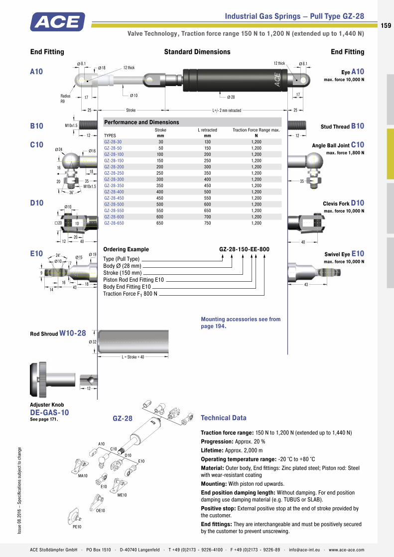
Industrial Gas Springs – Pull Type GZ-28
Valve Technology , Traction force range 150 N to 1,200 N (extended up to 1,440 N)
End Fitting End FittingStandard Dimensions
12
M10x1.5
35
18
17
25 L+/- 2 mm retracted
10
8.1
Stroke
RadiusR9
12 thick
25
12 thick
28 17
L = Stroke + 40
32
Ø Ø
Ø
43
Ø
10
20
10
12 40
20
Ø
Ø
Ø
35M10x1.5
16
24 16
18
20
36°
Ø Ø
12
8.1
40
24° 15 10
9
18
19
7
14 4316
ØØ
Ø
12
A10
MA10
ME10
C10D10
E10
OE10
PE10
E10
Technical Data
Traction force range: 150 N to 1,200 N (extended up to 1,440 N)Progression: Approx. 20 %Lifetime: Approx. 2,000 mOperating temperature range: -20 °C to +80 °CMaterial: Outer body, End fittings: Zinc plated steel; Piston rod: Steel with wear-resistant coatingMounting: With piston rod upwards.End position damping length: Without damping. For end position damping use damping material (e.g. TUBUS or SLAB).Positive stop: External positive stop at the end of stroke provided by the customer.End fittings: They are interchangeable and must be positively secured by the customer to prevent unscrewing.
Performance and Dimensions
TYPESStroke
mmL retracted
mmTraction Force Range max.
NGZ-28-30 30 130 1,200GZ-28-50 50 150 1,200GZ-28-100 100 200 1,200GZ-28-150 150 250 1,200GZ-28-200 200 300 1,200GZ-28-250 250 350 1,200GZ-28-300 300 400 1,200GZ-28-350 350 450 1,200GZ-28-400 400 500 1,200GZ-28-450 450 550 1,200GZ-28-500 500 600 1,200GZ-28-550 550 650 1,200GZ-28-600 600 700 1,200GZ-28-650 650 750 1,200
Ordering Example GZ-28-150-EE-800Type (Pull Type)Body Ø (28 mm)Stroke (150 mm)Piston Rod End Fitting E10Body End Fitting E10Traction Force F1 800 N
GZ-28
Mounting accessories see from page 194.
Eye A10 max. force 10,000 N
A10
Stud Thread B10 B10
Angle Ball Joint C10 max. force 1,800 N
C10
Clevis Fork D10 max. force 10,000 N
D10
Swivel Eye E10 max. force 10,000 N
E10
Rod Shroud W10-28
Adjuster Knob DE-GAS-10 See page 171.
159Is
sue
08.2
016
– Sp
ecifi
catio
ns s
ubje
ct to
cha
nge
ACE Stoßdämpfer GmbH . PO Box 1510 . D-40740 Langenfeld . T +49 (0)2173 - 9226-4100 . F +49 (0)2173 - 9226-89 . [email protected] . www.ace-ace.com

Industrial Gas Springs – Pull Type GZ-40
Valve Technology , Traction force range 500 N to 5,000 N (extended up to 7,000 N)
15
End Fitting End FittingStandard Dimensions
56
14
27
14
16 56
27
18
M14x1.5
45
25
21
40 L+/- 2 mm retracted
28
14.1
Stroke
RadiusR12.5
14 thick
40
14 thick
40 21
L = Stroke+ 40
45
45M14x1.5
20
30 22
25
28
36°
Ø
Ø Ø
Ø Ø
Ø
57
Ø
Ø
Ø
18
14.1
30° 20 14
19
30
26
13
18 5718
ØØØ
A14C14
D14
E14
ME14
ME14
ND14
Technical Data
Traction force range: 500 N to 5,000 N (extended up to 7,000 N)Progression: Approx. 40 %Lifetime: Approx. 2,000 mOperating temperature range: -20 °C to +80 °CMaterial: Outer body, End fittings: Zinc plated steel; Piston rod: Steel with wear-resistant coatingMounting: With piston rod upwards.End position damping length: Without damping. For end position damping use damping material (e.g. TUBUS or SLAB).Positive stop: External positive stop at the end of stroke provided by the customer.End fittings: They are interchangeable and must be positively secured by the customer to prevent unscrewing.
Performance and Dimensions
TYPESStroke
mmL retracted
mmTraction Force Range max.
NGZ-40-100 100 250 5,000GZ-40-150 150 325 5,000GZ-40-200 200 400 5,000GZ-40-250 250 475 5,000GZ-40-300 300 550 5,000GZ-40-400 400 700 5,000GZ-40-500 500 850 5,000GZ-40-600 600 1,000 5,000
Ordering Example GZ-40-150-EE-800Type (Pull Type)Body Ø (40 mm)Stroke (150 mm)Piston Rod End Fitting E14Body End Fitting E14Traction Force F1 800 N
GZ-40
Mounting accessories see from page 194.
Eye A14 max. force 10,000 N
A14
Stud Thread B14 B14
Angle Ball Joint C14 max. force 3,200 N
C14
Clevis Fork D14 max. force 10,000 N
D14
Swivel Eye E14 max. force 10,000 N
E14
Rod Shroud W14-40
Adjuster Knob DE-GAS-14 See page 171.
160
Issu
e 08
.201
6 –
Spec
ifica
tions
sub
ject
to c
hang
e
ACE Stoßdämpfer GmbH . PO Box 1510 . D-40740 Langenfeld . T +49 (0)2173 - 9226-4100 . F +49 (0)2173 - 9226-89 . [email protected] . www.ace-ace.com

For more information about the calculation
service see page 168!
ACE Digital Tools
Print catalogue? Everyone can. ACE offers more:
Downloads: Product information in many languages PC calculation software & online calculation service Extensive CAD component libraries ACE-YouTube-Channel with video tips VibroChecker – awarded free iPhone App
All information on our website: www.ace-ace.com

Filled with High Pressure Nitrogen Gas
Valve
Seals
Stainless Steel Outer Body
Main Bearing
Stainless Steel Piston Rod
Thread for End Fittings
Piston with Seals
Technical Data
Brilliant performance when things become tight: For specifi c use e.g. in tough surround-ings or small spaces, the broad spectrum of ACE industrial pull type gas springs made of stainless steel with body diameters from 15 to 40 mm supplements the comprehensive programme of the ACE industrial pull type gas springs with valves.
This high quality design is rust free and is more robust against environmental impact compared with standard gas pull type springs. These stainless steel gas springs are also optically appealing, very durable and available, upon request, in many stroke lengths and are also possible in many extension forces in combination with the suitable stainless steel accessories.
ACE industrial push type springs made of stainless steel are used in industries such as the chemical and food industry, in automo-biles, plant engineering and shipbuilding and also in medical, military, environmental and water supply technology.
GZ-15-V4A to GZ-40-VAIndustrial Gas Springs – Pull Type Very low progression rate with FDA approval
Industrial Gas Springs – Pull Type
Valve Technology, Stainless Steel
Traction force range: 40 N to 5,000 NPiston rod diameter: Ø 4 mm to Ø 28 mmProgression: Approx. 11 % to 40 %Lifetime: Approx. 2,000 mOperating temperature range: -20 °C to +80 °CMaterial: Outer body, Piston rod, End fi ttings: Stainless steel (1.4301/1.4305, AISI 304/303 and 1.4404/1.4571, AISI 316L/316Ti)Operating fl uid: Nitrogen gasMounting: With piston rod upwards.
End position damping length: Without damping. For end position damping use damping material (e.g. TUBUS or SLAB).Positive stop: External positive stop in the pulling direction provided by the customer.Application fi eld: Hoods, Shutters, Machine housing, Conveyor systemsEnd fi ttings: They are interchangeable and must be positively secured by the customer to prevent unscrewing.On request: Special oils and other special options. Alternative accessories. Traction gas
springs with end position damping also available on request. Other traction gas springs material 1.4404/1.4571, AISI 316L/316Ti (V4A) available on request.
162
Issu
e 08
.201
6 –
Spec
ifi ca
tions
sub
ject
to c
hang
e
ACE Stoßdämpfer GmbH . PO Box 1510 . D-40740 Langenfeld . T +49 (0)2173 - 9226-4100 . F +49 (0)2173 - 9226-89 . [email protected] . www.ace-ace.com
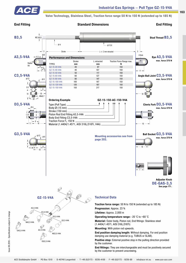
Filled with High Pressure Nitrogen Gas
Valve
Seals
Stainless Steel Outer Body
Main Bearing
Stainless Steel Piston Rod
Thread for End Fittings
Piston with Seals
Industrial Gas Springs – Pull Type GZ-15-V4A
Valve Technology, Stainless Steel , Traction force range 50 N to 150 N (extended up to 185 N)
16
4
8
4
5 16
8
Ø
End Fitting End FittingStandard Dimensions
7
1818
4
13 8
68
M3.5x0.6
18
5 L +/- 2 mm retracted
4
Stroke 5
15.6
ØØ
Ø
Ø Ø
18M4x0.7
8.5
13 8
6
10
36°
Ø Ø
11
8
11
4.1
6
8Ø
RadiusR4
4 thick
A3,5-V4A
C3,5-V4A
NA3,5-V4A
A3,5-V4A
NG3,5-V4A
OG3,5-V4A
OA3,5-V4A
D3,5-V4A
G3,5-V4A
Technical Data
Traction force range: 50 N to 150 N (extended up to 185 N)Progression: Approx. 23 %Lifetime: Approx. 2,000 mOperating temperature range: -20 °C to +80 °CMaterial: Outer body, Piston rod, End fi ttings: Stainless steel (1.4404/1.4571, AISI 316L/316Ti)Mounting: With piston rod upwards.End position damping length: Without damping. For end position damping use damping material (e.g. TUBUS or SLAB).Positive stop: External positive stop in the pulling direction provided by the customer.End fi ttings: They are interchangeable and must be positively secured by the customer to prevent unscrewing.
Performance and Dimensions
TYPESStroke
mmL retracted
mmTraction Force Range max.
NGZ-15-20-V4A 20 87 150GZ-15-40-V4A 40 107 150GZ-15-50-V4A 50 117 150GZ-15-60-V4A 60 127 150GZ-15-80-V4A 80 147 150GZ-15-100-V4A 100 167 150GZ-15-120-V4A 120 187 150GZ-15-150-V4A 150 217 150
Ordering Example GZ-15-150-AC-150-V4AType (Pull Type)Body Ø (15 mm)Stroke (150 mm)Piston Rod End Fitting A3,5-V4A Body End Fitting C3,5-V4ATraction Force F1 150 NMaterial (1.4404/1.4571, AISI 316L/316Ti, V4A)
GZ-15-V4A
Mounting accessories see from page 202.
Stud Thread B3,5 B3,5
Eye A3,5-V4A max. force 370 N
A3,5-V4A
Angle Ball Joint C3,5-V4A max. force 370 N
C3,5-V4A
Clevis Fork D3,5-V4A max. force 370 N
D3,5-V4A
Ball Socket G3,5-V4A max. force 370 N
G3,5-V4A
Adjuster Knob DE-GAS-3,5
See page 171.
163Is
sue
08.2
016
– Sp
ecifi
catio
ns s
ubje
ct to
cha
nge
ACE Stoßdämpfer GmbH . PO Box 1510 . D-40740 Langenfeld . T +49 (0)2173 - 9226-4100 . F +49 (0)2173 - 9226-89 . [email protected] . www.ace-ace.com
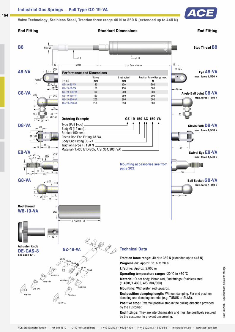
Industrial Gas Springs – Pull Type GZ-19-VA
Valve Technology, Stainless Steel , Traction force range 40 N to 350 N (extended up to 448 N)
10
End Fitting End FittingStandard Dimensions
3030
6
20 13
1513
M8x1.25
30
10 L +/- 2 mm retracted
6
Stroke 10
19
L = Stroke + 30
23
ØØ
Ø
Ø Ø
36
Ø
30M8x1.25
12
20 13
15
16.5
36°
Ø Ø
32
19
24° 12 8
12
16
16
6
12 3613
ØØ
Ø
8
16
8
10 32
16
Ø
22
11.5
19
8.1
10
14Ø
RadiusR7
10 thick
A8-VA
MA8-V4A
NG8-V4A
NA8-V4A
OG8-V4A
OA8-V4A
PA8-V4A
PG8-V4A
C8-VAD8-VA
E8-VAG8-VA
MA8-V4A
Technical Data
Traction force range: 40 N to 350 N (extended up to 448 N)Progression: Approx. 21 % to 28 %Lifetime: Approx. 2,000 mOperating temperature range: -20 °C to +80 °CMaterial: Outer body, Piston rod, End fittings: Stainless steel (1.4301/1.4305, AISI 304/303)Mounting: With piston rod upwards.End position damping length: Without damping. For end position damping use damping material (e.g. TUBUS or SLAB).Positive stop: External positive stop in the pulling direction provided by the customer.End fittings: They are interchangeable and must be positively secured by the customer to prevent unscrewing.
Performance and Dimensions
TYPESStroke
mmL retracted
mmTraction Force Range max.
NGZ-19-30-VA 30 130 300GZ-19-50-VA 50 150 300GZ-19-100-VA 100 200 300GZ-19-150-VA 150 250 300GZ-19-200-VA 200 300 300GZ-19-250-VA 250 350 300
Ordering Example GZ-19-150-AC-150-VAType (Pull Type)Body Ø (19 mm)Stroke (150 mm)Piston Rod End Fitting A8-VA Body End Fitting C8-VATraction Force F1 150 NMaterial (1.4301/1.4305, AISI 304/303, VA)
GZ-19-VA
Mounting accessories see from page 202.
Stud Thread B8 B8
Eye A8-VA max. force 1,560 N
A8-VA
Angle Ball Joint C8-VA max. force 1,140 N
C8-VA
Clevis Fork D8-VA max. force 1,560 N
D8-VA
Swivel Eye E8-VA max. force 1,560 N
E8-VA
Ball Socket G8-VA max. force 1,140 N
G8-VA
Rod Shroud W8-19-VA
Adjuster Knob DE-GAS-8 See page 171.
164
Issu
e 08
.201
6 –
Spec
ifica
tions
sub
ject
to c
hang
e
ACE Stoßdämpfer GmbH . PO Box 1510 . D-40740 Langenfeld . T +49 (0)2173 - 9226-4100 . F +49 (0)2173 - 9226-89 . [email protected] . www.ace-ace.com

Industrial Gas Springs – Pull Type GZ-28-VA
Valve Technology, Stainless Steel , Traction force range 150 N to 1,200 N (ext. up to 1,460 N)
12
End Fitting End FittingStandard Dimensions
M10x1.5
35
12 12
L = Stroke + 40
32
43
Ø
35M10x1.5
16
24 16
18
20
36°
Ø Ø
40
27
24° 15 10
14
18
19
7
14 4316
ØØ
Ø
10
20
10
12 40
20
Ø
26.5
15
27
8.1
15
18Ø
RadiusR9
10 thickL +/- 2 mm retracted
10
Stroke
28Ø Ø
A10-VA
MA10-V4A
C10-VA
D10-VAE10-VA
Technical Data
Traction force range: 150 N to 1,200 N (extended up to 1,460 N)Progression: Approx. 22 %Lifetime: Approx. 2,000 mOperating temperature range: -20 °C to +80 °CMaterial: Outer body, Piston rod, End fittings: Stainless steel (1.4301/1.4305, AISI 304/303)Mounting: With piston rod upwards.End position damping length: Without damping. For end position damping use damping material (e.g. TUBUS or SLAB).Positive stop: External positive stop in the pulling direction provided by the customer.End fittings: They are interchangeable and must be positively secured by the customer to prevent unscrewing.
Performance and Dimensions
TYPESStroke
mmL retracted
mmTraction Force Range max.
NGZ-28-50-VA 50 165 1,200GZ-28-100-VA 100 215 1,200GZ-28-150-VA 150 265 1,200GZ-28-200-VA 200 315 1,200GZ-28-250-VA 250 365 1,200GZ-28-300-VA 300 415 1,200GZ-28-350-VA 350 465 1,200GZ-28-400-VA 400 515 1,200GZ-28-450-VA 450 565 1,200GZ-28-500-VA 500 615 1,200GZ-28-550-VA 550 665 1,200GZ-28-600-VA 600 715 1,200
Ordering Example GZ-28-150-EE-800-VAType (Pull Type)Body Ø (28 mm)Stroke (150 mm)Piston Rod End Fitting E10-VA Body End Fitting E10-VATraction Force F1 800 NMaterial (1.4301/1.4305, AISI 304/303, VA)
GZ-28-VA
Mounting accessories see from page 202.
Stud Thread B10 B10
Eye A10-VA max. force 3,800 N
A10-VA
Angle Ball Joint C10-VA max. force 1,750 N
C10-VA
Clevis Fork D10-VA max. force 3,800 N
D10-VA
Swivel Eye E10-VA max. force 3,800 N
E10-VA
Rod Shroud W10-28-VA
Adjuster Knob DE-GAS-10 See page 171.
165Is
sue
08.2
016
– Sp
ecifi
catio
ns s
ubje
ct to
cha
nge
ACE Stoßdämpfer GmbH . PO Box 1510 . D-40740 Langenfeld . T +49 (0)2173 - 9226-4100 . F +49 (0)2173 - 9226-89 . [email protected] . www.ace-ace.com

Industrial Gas Springs – Pull Type GZ-40-VA
Valve Technology, Stainless Steel , Traction force range 500 N to 5,000 N (ext. up to 7,000 N)
15
End Fitting End FittingStandard Dimensions
M14x1.5
45
18 L +/- 2 mm retracted
28
Stroke 18
40
L = Stroke + 40
45
Ø Ø
57
Ø
45M14x1.5
20
30 22
25
28
36°
Ø Ø
56
42
30° 20 14
19
30
26
13
18 5718
ØØ
Ø
14
27
14
16 56
27
Ø
35
19.5
42
14.1
20
25Ø
RadiusR12.5
14 thick
A14-VAC14-VA
D14-VA
E14-VA
ME14-VA
ME14-VA
ND14-VA
Technical Data
Traction force range: 500 N to 5,000 N (extended up to 7,000 N)Progression: Approx. 40 %Lifetime: Approx. 2,000 mOperating temperature range: -20 °C to +80 °CMaterial: Outer body, Piston rod, End fittings: Stainless steel (1.4301/1.4305, AISI 304/303)Mounting: With piston rod upwards.End position damping length: Without damping. For end position damping use damping material (e.g. TUBUS or SLAB).Positive stop: External positive stop in the pulling direction provided by the customer.End fittings: They are interchangeable and must be positively secured by the customer to prevent unscrewing.
Performance and Dimensions
TYPESStroke
mmL retracted
mmTraction Force Range max.
NGZ-40-100-VA 100 250 5,000GZ-40-150-VA 150 325 5,000GZ-40-200-VA 200 400 5,000GZ-40-250-VA 250 475 5,000GZ-40-300-VA 300 550 5,000GZ-40-400-VA 400 700 5,000GZ-40-500-VA 500 850 5,000GZ-40-600-VA 600 1,000 5,000
Ordering Example GZ-40-150-EE-800-VAType (Pull Type)Body Ø (40 mm)Stroke (150 mm)Piston Rod End Fitting E14-VA Body End Fitting E14-VATraction Force F1 800 NMaterial (1.4301/1.4305, AISI 304/303, VA)
GZ-40-VA
Mounting accessories see from page 202.
Stud Thread B14 B14
Eye A14-VA max. force 7,000 N
A14-VA
Angle Ball Joint C14-VA
max. force 3,200 N
C14-VA
Clevis Fork D14-VA max. force 7,000 N
D14-VA
Swivel Eye E14-VA max. force 7,000 N
E14-VA
Rod Shroud W14-40-VA
Adjuster Knob DE-GAS-14 See page 171.
166
Issu
e 08
.201
6 –
Spec
ifica
tions
sub
ject
to c
hang
e
ACE Stoßdämpfer GmbH . PO Box 1510 . D-40740 Langenfeld . T +49 (0)2173 - 9226-4100 . F +49 (0)2173 - 9226-89 . [email protected] . www.ace-ace.com

Stainless Steel Gas Springs – Pull Type (V4A)
Performance
TYPESStroke
mmL retracted
mmDimensions see Page
GZ-19-30-V4A 30 130 164GZ-19-50-V4A 50 150 164GZ-19-150-V4A 150 250 164GZ-19-200-V4A 200 300 164GZ-19-250-V4A 250 350 164GZ-28-50-V4A 50 165 165GZ-28-100-V4A 100 215 165GZ-28-150-V4A 150 265 165GZ-28-200-V4A 200 315 165GZ-28-250-V4A 250 365 165GZ-28-300-V4A 300 415 165GZ-28-350-V4A 350 465 165GZ-28-400-V4A 400 515 165GZ-28-450-V4A 450 565 165GZ-28-500-V4A 500 615 165GZ-28-550-V4A 550 665 165GZ-28-600-V4A 600 715 165GZ-40-100-V4A 100 250 166GZ-40-150-V4A 150 325 166GZ-40-200-V4A 200 400 166GZ-40-250-V4A 250 475 166GZ-40-300-V4A 300 550 166GZ-40-400-V4A 400 700 166GZ-40-500-V4A 500 850 166GZ-40-600-V4A 600 1,000 166
End Fittings
TYPESDimensions see Page
A5-V4A 204C5-V4A 204D5-V4A 204E5-V4A 204G5-V4A 204A8-V4A 205C8-V4A 205D8-V4A 205E8-V4A 205G8-V4A 206
End Fittings
TYPESDimensions see Page
A10-V4A 206C10-V4A 206D10-V4A 206E10-V4A 206A14-V4A 207C14-V4A 207D14-V4A 207E14-V4A 207
Further Stainless Steel Gas Springs (Pull Type), V4A
Further Stainless Steel Accessories, V4A
167Is
sue
08.2
016
– Sp
ecifi
catio
ns s
ubje
ct to
cha
nge
ACE Stoßdämpfer GmbH . PO Box 1510 . D-40740 Langenfeld . T +49 (0)2173 - 9226-4100 . F +49 (0)2173 - 9226-89 . [email protected] . www.ace-ace.com

168168
ACE Stoßdämpfer GmbH . PO Box 1510 . D-40740 Langenfeld . T +49 (0)2173 - 9226-4100 . [email protected] . www.ace-ace.com
Issu
e 08
.201
6 –
Spec
ifica
tions
sub
ject
to c
hang
e
Gas Springs
Calculation Service
Free Calculation Offer for Industrial Gas SpringsWith all necessary information for installation
To obtain the optimum operation with minimal hand force, the gas spring must be properly sized and the mounting points have to be optimally placed.
It is important to identify the following points: • gas spring size
• required gas spring stroke
• mounting points on flap and frame
• extended length of the gas spring
• required extension force
• hand forces throughout the complete movement on the flap
With our free calculation service you can eliminate the time-consuming calculation and send us your details by fax or e-mail. Just complete the information shown on the following page. Please attach a sketch of your application (a simple hand sketch is sufficient) in side view. Our application engineers will determine the optimum gas springs and mounting points and calculate the ideal situation to satisfy your requirements.You will receive a quotation showing the opening and closing forces and our recommended mounting points to suit your application.
Example of a Calculation Offer
NEW! Also try our Online Calculation Service: www.ace-ace.com
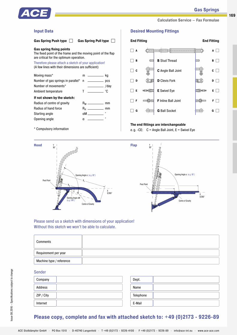
169Is
sue
08.2
016
– Sp
ecifi
catio
ns s
ubje
ct to
cha
nge
ACE Stoßdämpfer GmbH . PO Box 1510 . D-40740 Langenfeld . T +49 (0)2173 - 9226-4100 . F +49 (0)2173 - 9226-89 . [email protected] . www.ace-ace.com
A
B
C
D
E
F
G
A
B
C
D
E
F
G
B Stud Thread
C Angle Ball Joint
D Clevis Fork
E Swivel Eye
F Inline Ball Joint
G Ball Socket
RH
Opening Angle α (e.g. 88°)
Centre of Gravity
Starting Angle αM(e.g. 348°)
X0/360°
Y90°
RM
Pivot Point
Opening Angle α (e.g. 88°)
Centre of Gravity
Pivot Point
Y90°
X0/360°
Please copy, complete and fax with attached sketch to: +49 (0)2173 - 9226-89
Input Data Gas Spring Push type Gas Spring Pull type Gas spring fixing pointsThe fixed point of the frame and the moving point of the flap are critical for the optimum operation. Therefore please attach a sketch of your application! (A few lines with their dimensions are sufficient)
Moving mass* m kgNumber of gas springs in parallel* n pcsNumber of movements* /dayAmbient temperature T °C
If not shown by the sketch:Radius of centre of gravity RM mmRadius of hand force RH mmStarting angle αM °Opening angle α °
* Compulsory informationThe end fittings are interchangeablee.g. -CE: C = Angle Ball Joint, E = Swivel Eye
Desired Mounting Fittings
End FittingEnd Fitting
Sender
Hood Flap
Please send us a sketch with dimensions of your application! Without this sketch we won’t be able to calculate.
Gas Springs
Calculation Service – Fax Formulae
Internet
ZIP / City
Address
Company
Telephone
Name
Dept.
Machine type / reference
Requirement per year
Comments
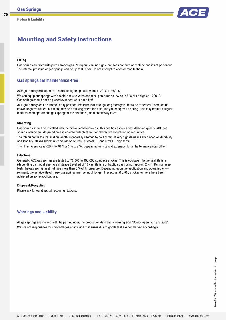
170
Issu
e 08
.201
6 –
Spec
ifica
tions
sub
ject
to c
hang
e
ACE Stoßdämpfer GmbH . PO Box 1510 . D-40740 Langenfeld . T +49 (0)2173 - 9226-4100 . F +49 (0)2173 - 9226-89 . [email protected] . www.ace-ace.com
Gas Springs
Notes & Liability
Mounting and Safety Instructions
Filling Gas springs are filled with pure nitrogen gas. Nitrogen is an inert gas that does not burn or explode and is not poisonous. The internal pressure of gas springs can be up to 300 bar. Do not attempt to open or modify them!
Gas springs are maintenance-free!
ACE gas springs will operate in surrounding temperatures from -20 °C to +80 °C. We can equip our springs with special seals to withstand tem- peratures as low as -45 °C or as high as +200 °C. Gas springs should not be placed over heat or in open fire! ACE gas springs can be stored in any position. Pressure lost through long storage is not to be expected. There are no known negative values, but there may be a sticking effect the first time you compress a spring. This may require a higher initial force to operate the gas spring for the first time (initial breakaway force).
Mounting Gas springs should be installed with the piston rod downwards. This position ensures best damping quality. ACE gas springs include an integrated grease chamber which allows for alternative mount-ing opportunities.The tolerance for the installation length is generally deemed to be ± 2 mm. If very high demands are placed on durability and stability, please avoid the combination of small diameter + long stroke + high force. The filling tolerance is -20 N to 40 N or 5 % to 7 %. Depending on size and extension force the tolerances can differ.
Life Time Generally, ACE gas springs are tested to 70,000 to 100,000 complete strokes. This is equivalent to the seal lifetime (depending on model size) to a distance travelled of 10 km (lifetime of traction gas springs approx. 2 km). During these tests the gas spring must not lose more than 5 % of its pressure. Depending upon the application and operating envi-ronment, the service life of these gas springs may be much longer. In practise 500,000 strokes or more have been achieved on some applications.
Disposal/Recycling Please ask for our disposal recommendations.
Warnings and Liability
All gas springs are marked with the part number, the production date and a warning sign “Do not open high pressure”. We are not responsible for any damages of any kind that arises due to goods that are not marked accordingly.

171Is
sue
08.2
016
– Sp
ecifi
catio
ns s
ubje
ct to
cha
nge
ACE Stoßdämpfer GmbH . PO Box 1510 . D-40740 Langenfeld . T +49 (0)2173 - 9226-4100 . F +49 (0)2173 - 9226-89 . [email protected] . www.ace-ace.com
You can also visit our Youtube channel at www.youtube.com/user/acecontrolsglobal Here, among other things you will fi nd an ACETips-Video on the topic of DE-GAS!
The refi lling kit contains all fi lling bells and adjuster knobs for the current ACE gas spring range. Gas springs fi lled with the refi lling kit must be measured on a calibrated measurement system by ACE for repeat production.
The refi lling kit suits 200 bar nitrogen bottles with a thread of W24,32x1/14" (German standard). Other connections are available upon request.
DE-GAS
Valve Actuation with ACE DE-GASSimple, safe and reliable
Gas Spring Refi lling KitFlexible and easy to use
De-gassing for controlled force reduction on valve gas springs The reduction is made by screwing the DE-Gas on the male screwed end of the gas spring. The drain process is possible through light actuation of the push button. If too much nitrogen is discharged, the gas spring can be refi lled by ACE.
Adjustment1. Hold gas spring valve up.2. Insert DE-GAS adjuster knob on thread of the valve.3. Press the DE-GAS adjuster knob with light hand force until you can hear the nitrogen escaping.
Press only briefl y to avoid too much nitrogen being discharged.4. After adjustment, remove the DE-GAS adjuster knob, mount the end fi ttings and test the gas
spring in your application. If necessary repeat the procedure.
If you use 2 gas springs in parallel, both gas springs should have the same force to avoid bending forces or side load on the application. If necessary return to ACE to refi ll both gas springs to the same (average) force. If too much nitrogen is discharged, the units can be returned to ACE for re-gassing.
Part number: GS-FK-C
The ACE gas spring refi lling kit offers you the opportunity to fi ll gas springs on location or adapt them individually. The refi lling kit is equipped with all the parts you need to fi ll gas springs. Very precise fi lling of the gas springs is possible using the digital manometer. The table for determining the fi lling pressure of the gas springs is included with the case. The only thing missing from the delivery is the nitrogen.
Gas Springs – Special Accessories
Valve Actuation & Refi lling Kit

Hydraulic DampersMulti-talent in speed control
The hydraulic dampers are similar in appearance to the ACE industrial gas springs but are adjusted in the end position and work differently to the DVC family with individual speed adjusters for the push and pull direction. This provide users with the maximum flexibility.
Whether used as drive compensation or safety elements, the retraction and extension speed of these ACE solutions can always be precisely set. This means that the speed of movement can be controlled, synchronisation regulated in both directions and pivoting loads can be compensated. Depending on the model, the push and pull forces are between 30 and 40,000 N. These maintenance-free, ready-to-install products are available in body diameters of 12 to 70 mm and in stroke lengths up to 800 mm.
Motion Control172172
ACE Stoßdämpfer GmbH . PO Box 1510 . D-40740 Langenfeld . T +49 (0)2173 - 9226-4100 . [email protected] . www.ace-ace.com
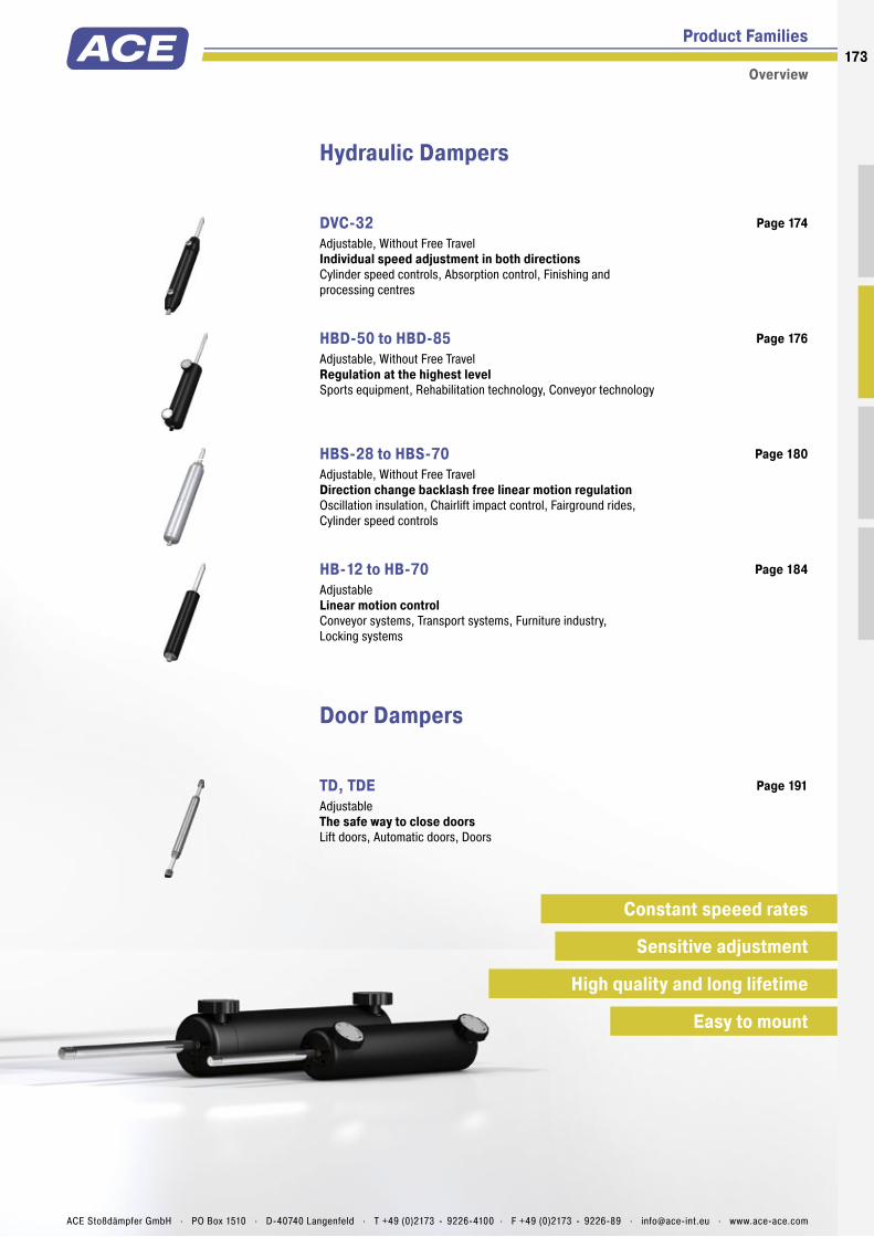
Product Families
Overview
Hydraulic Dampers
DVC-32 Adjustable, Without Free Travel Individual speed adjustment in both directionsCylinder speed controls, Absorption control, Finishing and processing centres
Page 174
HBD-50 to HBD-85 Adjustable, Without Free Travel Regulation at the highest levelSports equipment, Rehabilitation technology, Conveyor technology
Page 176
HBS-28 to HBS-70 Adjustable, Without Free Travel Direction change backlash free linear motion regulationOscillation insulation, Chairlift impact control, Fairground rides, Cylinder speed controls
Page 180
HB-12 to HB-70 Adjustable Linear motion controlConveyor systems, Transport systems, Furniture industry, Locking systems
Page 184
Door Dampers
TD, TDE Adjustable The safe way to close doorsLift doors, Automatic doors, Doors
Page 191
Constant speeed rates
Sensitive adjustment
Easy to mount
High quality and long lifetime
173
ACE Stoßdämpfer GmbH . PO Box 1510 . D-40740 Langenfeld . T +49 (0)2173 - 9226-4100 . F +49 (0)2173 - 9226-89 . [email protected] . www.ace-ace.com

Piston Rod
Main Bearing
Accumulator
Outer Body
Piston
Seal
Pressure Chamber
Adjustment Segment for Compression Speed
Thread for End Fittings
Adjustment Segment for Extension Speed
Technical Data
Can be regulated separately in any stroke position: The hydraulic dampers in the DVC-32 model are the fi rst model to have the ability to have the in and out speeds adjusted inde-pendently from the outside and therefore more precisely. With their individual adjustment segments for the push and pull direction as well as the double-sided action, these are suitable as safety or control elements.
The great number of mounting accessories makes assembly of these hydraulic dampers by ACE easier and allows these maintenance-free, ready-to-install and self-contained systems universally applicable. Qualitatively high grade, and at the same time simple to use; one of their uses is to absorb swinging loads.
These machine elements are used, for one, in the automotive sector and industrial applica-tions as well as in mechanical engineering and the electronics industry.
DVC-32Hydraulic Dampers Individual speed adjustment in both directions
Hydraulic Dampers
Adjustable, Without Free Travel
Compression and extension force: 42 N to 2,000 NOuter body diameter: Ø 32 mmPiston rod diameter: Ø 8 mmLifetime: Approx. 10,000 mOperating temperature range: 0 °C to 65 °CAdjustment: Steplessly adjustablePositive stop: External positive stops 1 mm to 1.5 mm before the end of stroke provided by the customer.Damping medium: Automatic Transmission Fluid (ATF)
Material: Outer body: Coated aluminium; Piston rod: Black anodized aluminium; End fi ttings: Zinc plated steelMounting: In any positionApplication fi eld: Cylinder speed controls, Absorption control, Finishing and processing centresNote: Increased break-away force if unit has not moved for some time. Damping force can be adjusted after installation.End fi ttings: They are interchangeable and must be positively secured by the customer to prevent unscrewing.
On request: Special oils and other special options. Alternative accessories available on request.
174
Issu
e 08
.201
6 –
Spec
ifi ca
tions
sub
ject
to c
hang
e
ACE Stoßdämpfer GmbH . PO Box 1510 . D-40740 Langenfeld . T +49 (0)2173 - 9226-4100 . F +49 (0)2173 - 9226-89 . [email protected] . www.ace-ace.com

Piston Rod
Main Bearing
Accumulator
Outer Body
Piston
Seal
Pressure Chamber
Adjustment Segment for Compression Speed
Thread for End Fittings
Adjustment Segment for Extension Speed
Hydraulic Dampers DVC-32EU
Adjustable, Without Free Travel , Compression and extension force 42 N to 2,000 N
9
M8x1.25
30
14
14
20 L+/- 2 mm extended
8
8.1
Stroke
RadiusR7
10 thick
20
10 thick
3214Ø
Ø
Ø
36
Ø
8
16
8
10 32
16
Ø
Ø
30M8x1.25
12
20 13
15
16.5
36°
Ø Ø
8
8.1
32
24° 12 8
8
16
16
6
12 3613
ØØØ
20 22
14Ø10
End Fitting End FittingStandard Dimensions
Mounting accessories see from page 194.
Model Type Prefi xP: Damping in both directions (standard model)M: Damping on out stroke only (adjustment knob at “rear end” free fl ow)N: Damping on in stroke only (adjustment knob at “piston rod end” free fl ow)
Performance and Dimensions
TYPESStroke
mmL extended
mm1 Compression Force max.
NDVC-32-50EU 50 240 2,000DVC-32-100EU 100 340 1,670DVC-32-150EU 150 440 1,335
1 Max. extension force for all stroke lengths 2,000 N.
Ordering Example DVC-32-50EU-DD-PType (Hydraulic Damper)Body Ø (32 mm)Stroke (50 mm)EU CompliantPiston Rod End Fitting D8Body End Fitting D8Damping Direction (P = both directions)
End fi ttings: They are interchangeable and must be positively secured by the customer to prevent unscrewing.
Eye A8max. force 3.000 N
A8
Stud Thread B8
B8
Angle Ball Joint C8max. force 1,200 N
C8
Clevis Fork D8max. force 3,000 N
D8
Swivel Eye E8max. force 3,000 N
E8
6.4 A max
13
8
6
B 32
141030 30
6
12.7 thick
10
ØØ
ØØ
Ø
Ø
DVC-32EU-xx
Performance and Dimensions
TYPESStroke
mmA max.
mmB
mmCompression Force max.
NTraction Force Range max.
NDVC-32-50EU-XX 50 250 75.2 2,000 2,000DVC-32-100EU-XX 100 350 124.4 1,670 2,000DVC-32-150EU-XX 150 450 173.6 1,335 2,000
175Is
sue
08.2
016
– Sp
ecifi
catio
ns s
ubje
ct to
cha
nge
ACE Stoßdämpfer GmbH . PO Box 1510 . D-40740 Langenfeld . T +49 (0)2173 - 9226-4100 . F +49 (0)2173 - 9226-89 . [email protected] . www.ace-ace.com
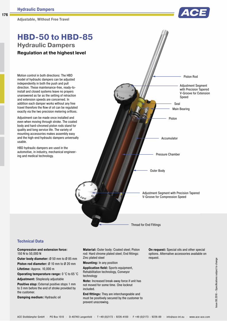
Piston Rod
Accumulator
Thread for End Fittings
Pressure Chamber
Seal
Piston
Adjustment Segment with Precision Tapered V-Groove for Extension Speed
Main Bearing
Outer Body
Adjustment Segment with Precision Tapered V-Groove for Compression Speed
Technical Data
Motion control in both directions: The HBD model of hydraulic dampers can be adjusted independently in both the push and pull direction. These maintenance-free, ready-to-install and closed systems leave no prayers unanswered as far as the setting of retraction and extension speeds are concerned. In addition each damper works without any free travel therefore the fl ow of oil can be regulated exactly via the two precision metering orifi ces.
Adjustment can be made once installed and even when moving through stroke. The coated body and hard-chromed piston rods stand for quality and long service life. The variety of mounting accessories makes assembly easy and the high-end hydraulic dampers universally usable.
HBD hydraulic dampers are used in the automotive, in industry, mechanical engineer-ing and medical technology.
HBD-50 to HBD-85Hydraulic Dampers Regulation at the highest level
Hydraulic Dampers
Adjustable, Without Free Travel
Compression and extension force: 150 N to 50,000 NOuter body diameter: Ø 50 mm to Ø 85 mmPiston rod diameter: Ø 10 mm to Ø 20 mmLifetime: Approx. 10,000 mOperating temperature range: 0 °C to 65 °CAdjustment: Steplessly adjustablePositive stop: External positive stops 1 mm to 3 mm before the end of stroke provided by the customer.Damping medium: Hydraulic oil
Material: Outer body: Coated steel; Piston rod: Hard chrome plated steel; End fi ttings: Zinc plated steelMounting: In any positionApplication fi eld: Sports equipment, Rehabilitation technology, Conveyor technologyNote: Increased break-away force if unit has not moved for some time. One locknut included.End fi ttings: They are interchangeable and must be positively secured by the customer to prevent unscrewing.
On request: Special oils and other special options. Alternative accessories available on request.
176
Issu
e 08
.201
6 –
Spec
ifi ca
tions
sub
ject
to c
hang
e
ACE Stoßdämpfer GmbH . PO Box 1510 . D-40740 Langenfeld . T +49 (0)2173 - 9226-4100 . F +49 (0)2173 - 9226-89 . [email protected] . www.ace-ace.com
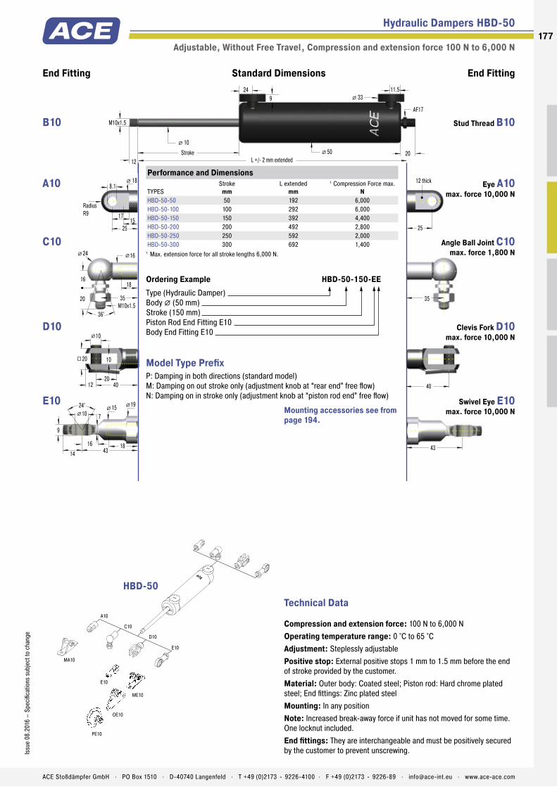
Piston Rod
Accumulator
Thread for End Fittings
Pressure Chamber
Seal
Piston
Adjustment Segment with Precision Tapered V-Groove for Extension Speed
Main Bearing
Outer Body
Adjustment Segment with Precision Tapered V-Groove for Compression Speed
Hydraulic Dampers HBD-50
Adjustable, Without Free Travel , Compression and extension force 100 N to 6,000 N
End Fitting End FittingStandard Dimensions
25
12 thick
17
25
8.1
15
� 18
RadiusR9
35
12 L +/- 2 mm extendedStroke 2050
� 10�
43
40
M10x1.5
� 3324 11.5
9
AF17
10
20
10
12 40
20
35M10x1.5
16
24 16
18
20
36°
�
� �
24° 15 10
9
18
19
7
14 4316
���
ACE
123
4 5 6
ACE
123
4 5 6
A10
C10
D10
E10
MA10
ME10
PE10
OE10
E10
Technical Data
Compression and extension force: 100 N to 6,000 NOperating temperature range: 0 °C to 65 °CAdjustment: Steplessly adjustablePositive stop: External positive stops 1 mm to 1.5 mm before the end of stroke provided by the customer.Material: Outer body: Coated steel; Piston rod: Hard chrome plated steel; End fi ttings: Zinc plated steelMounting: In any positionNote: Increased break-away force if unit has not moved for some time. One locknut included.End fi ttings: They are interchangeable and must be positively secured by the customer to prevent unscrewing.
Model Type Prefi xP: Damping in both directions (standard model)M: Damping on out stroke only (adjustment knob at “rear end” free fl ow)N: Damping on in stroke only (adjustment knob at “piston rod end” free fl ow)
Performance and Dimensions
TYPESStroke
mmL extended
mm1 Compression Force max.
NHBD-50-50 50 192 6,000HBD-50-100 100 292 6,000HBD-50-150 150 392 4,400HBD-50-200 200 492 2,800HBD-50-250 250 592 2,000HBD-50-300 300 692 1,400
1 Max. extension force for all stroke lengths 6,000 N.
Ordering Example HBD-50-150-EEType (Hydraulic Damper)Body � (50 mm)Stroke (150 mm)Piston Rod End Fitting E10Body End Fitting E10
HBD-50
Mounting accessories see from page 194.
Stud Thread B10 B10
Eye A10 max. force 10,000 N
A10
Angle Ball Joint C10 max. force 1,800 N
C10
Clevis Fork D10 max. force 10,000 N
D10
Swivel Eye E10 max. force 10,000 N
E10
177Is
sue
08.2
016
– Sp
ecifi
catio
ns s
ubje
ct to
cha
nge
ACE Stoßdämpfer GmbH . PO Box 1510 . D-40740 Langenfeld . T +49 (0)2173 - 9226-4100 . F +49 (0)2173 - 9226-89 . [email protected] . www.ace-ace.com

Hydraulic Dampers HBD-70
Adjustable, Without Free Travel , Compression and extension force 150 N to 10,000 N
End Fitting End FittingStandard Dimensions
40
14 thick
21
40
14.1
1812
25Ø
RadiusR12.5
45
15 L +/- 2 mm extended
14Stroke
1770
Ø
Ø
57
14
27
14
16 56
27
Ø
45M14x1.5
20
30 22
25
28
36°
Ø Ø
56
30° 20 14
19
30
26
13
18 5718
ØØ
Ø
M14x1.5
Ø 4524 17
14
8
AF17
ACE
123
4 5 6
ACE
123
4 5 6
A14
C14
ME14
ND14
ME14
D14
E14
Technical Data
Compression and extension force: 150 N to 10,000 NOperating temperature range: 0 °C to 65 °CAdjustment: Steplessly adjustablePositive stop: External positive stops 1 mm to 1.5 mm before the end of stroke provided by the customer.Material: Outer body: Coated steel; Piston rod: Hard chrome plated steel; End fittings: Zinc plated steelMounting: In any positionNote: Increased break-away force if unit has not moved for some time. One locknut included.End fittings: They are interchangeable and must be positively secured by the customer to prevent unscrewing.
Model Type PrefixP: Damping in both directions (standard model)M: Damping on out stroke only (adjustment knob at “rear end” free flow)N: Damping on in stroke only (adjustment knob at “piston rod end” free flow)
Performance and Dimensions
TYPESStroke
mmL extended
mm1 Compression Force max.
NHBD-70-100 100 314 10,000HBD-70-150 150 414 10,000HBD-70-200 200 514 10,000HBD-70-300 300 714 10,000HBD-70-400 400 914 8,000HBD-70-500 500 1,114 6,000
1 Max. extension force for all stroke lengths 10,000 N.
Ordering Example HBD-70-300-EEType (Hydraulic Damper)Body Ø (70 mm)Stroke (300 mm)Piston Rod End Fitting E14Body End Fitting E14
HBD-70
Mounting accessories see from page 194.
Stud Thread B14 B14
Eye A14 max. force 10,000 N
A14
Angle Ball Joint C14 max. force 3,200 N
C14
Clevis Fork D14 max. force 10,000 N
D14
Swivel Eye E14 max. force 10,000 N
E14
178
Issu
e 08
.201
6 –
Spec
ifica
tions
sub
ject
to c
hang
e
ACE Stoßdämpfer GmbH . PO Box 1510 . D-40740 Langenfeld . T +49 (0)2173 - 9226-4100 . F +49 (0)2173 - 9226-89 . [email protected] . www.ace-ace.com
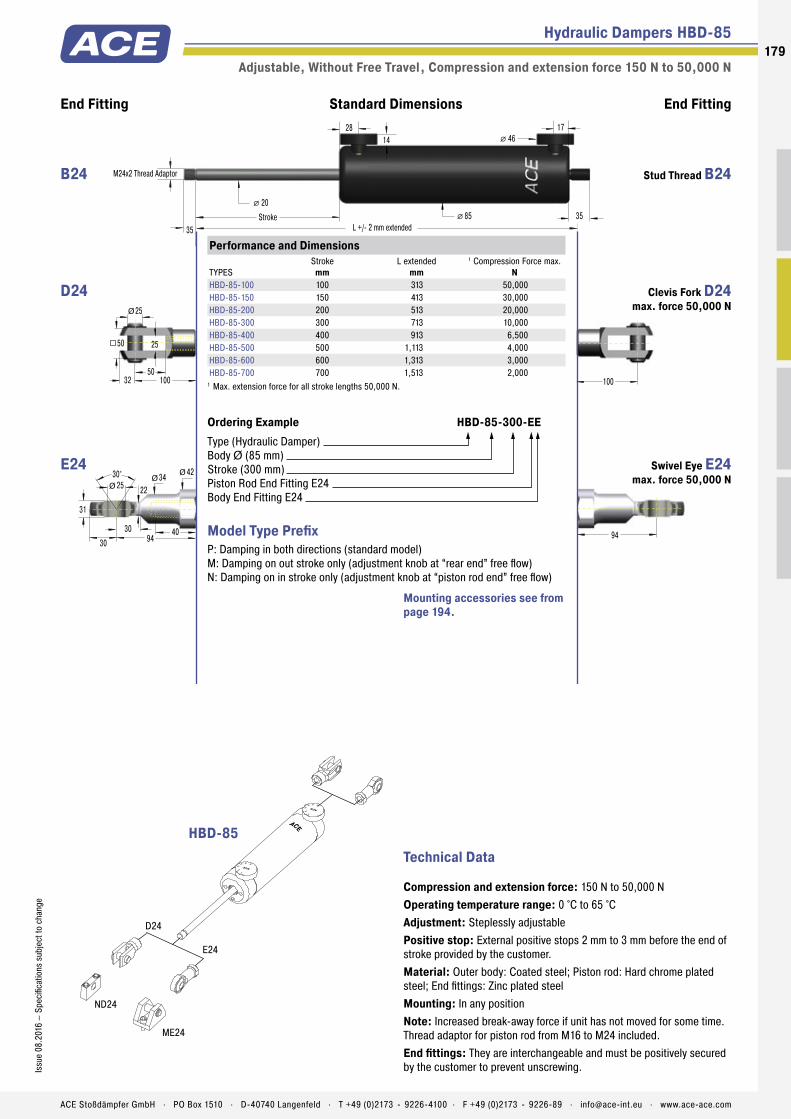
Hydraulic Dampers HBD-85
Adjustable, Without Free Travel , Compression and extension force 150 N to 50,000 N
End Fitting End FittingStandard Dimensions
35 L +/- 2 mm extendedStroke 3585
� 20�
M24x2 Thread Adaptor
� 4628 17
14
94
25
50
25
32 100
50
Ø
100
30° 34 25
31
40
42
22
30 9430
ØØ
Ø
ACE
123
4 5 6
ACE
123
4 5 6
D24
E24
ME24
ND24
Technical Data
Compression and extension force: 150 N to 50,000 NOperating temperature range: 0 °C to 65 °CAdjustment: Steplessly adjustablePositive stop: External positive stops 2 mm to 3 mm before the end of stroke provided by the customer.Material: Outer body: Coated steel; Piston rod: Hard chrome plated steel; End fittings: Zinc plated steelMounting: In any positionNote: Increased break-away force if unit has not moved for some time. Thread adaptor for piston rod from M16 to M24 included.End fittings: They are interchangeable and must be positively secured by the customer to prevent unscrewing.
Model Type PrefixP: Damping in both directions (standard model)M: Damping on out stroke only (adjustment knob at “rear end” free flow)N: Damping on in stroke only (adjustment knob at “piston rod end” free flow)
Performance and Dimensions
TYPESStroke
mmL extended
mm1 Compression Force max.
NHBD-85-100 100 313 50,000HBD-85-150 150 413 30,000HBD-85-200 200 513 20,000HBD-85-300 300 713 10,000HBD-85-400 400 913 6,500HBD-85-500 500 1,113 4,000HBD-85-600 600 1,313 3,000HBD-85-700 700 1,513 2,000
1 Max. extension force for all stroke lengths 50,000 N.
Ordering Example HBD-85-300-EEType (Hydraulic Damper)Body Ø (85 mm)Stroke (300 mm)Piston Rod End Fitting E24Body End Fitting E24
HBD-85
Mounting accessories see from page 194.
Stud Thread B24 B24
Clevis Fork D24 max. force 50,000 N
D24
Swivel Eye E24 max. force 50,000 N
E24
179Is
sue
08.2
016
– Sp
ecifi
catio
ns s
ubje
ct to
cha
nge
ACE Stoßdämpfer GmbH . PO Box 1510 . D-40740 Langenfeld . T +49 (0)2173 - 9226-4100 . F +49 (0)2173 - 9226-89 . [email protected] . www.ace-ace.com

Piston Rod
Main Bearing
Balance Chamber
Outer Body
Piston
Seal
Pressure Chamber
Intermediate Bearing and Fixed Separator
Thread for End Fittings
Tooth Adjustment
Metering Orifice
Technical Data
Damping either in one or both directions: The HBS models of hydraulic dampers are made in a slim gas spring design and are compact and high in performance. Maintenance-free and ready-to-install they allow precise setting of retraction and extension speeds without any free travel when changing direction.
These hydraulic dampers offer constant feeding rates and can be fi nely tuned via the screw adjustment. A control segment on the piston makes the adjustment at the end position child’s play. Thanks to many add-on components the assembly is easy to mount, so that the damper can be universally deployed for damping back and forth swinging masses, such as in power or free conveyors.
In addition to the automotive sector, the application areas are industrial applications, classic mechanical engineering, the electron-ics and furniture industry and medical technology.
HBS-28 to HBS-70Hydraulic Dampers Direction change backlash free linear motion regulation
Hydraulic Dampers
Adjustable, Without Free Travel
Compression and extension force: 30 N to 40,000 NOuter body diameter: Ø 28 mm to Ø 70 mmPiston rod diameter: Ø 8 mm to Ø 30 mmLifetime: Approx. 10,000 mOperating temperature range: -20 °C to +80 °CAdjustment: Achieved by turning the piston rod in its fully extended or compressed position.Positive stop: External positive stops 1 mm to 6 mm before the end of stroke provided by the customer.
Damping medium: Hydraulic oilMaterial: Outer body: Zinc plated or coated steel; Piston rod: Hard chrome plated steel; End fi ttings: Zinc plated steelMounting: In any positionApplication fi eld: Oscillation insulation, Chairlift impact control, Fairground rides, Cylinder speed controlsNote: Increased break-away force if unit has not moved for some time.End fi ttings: They are interchangeable and must be positively secured by the customer to prevent unscrewing.
Safety instructions: For long strokes with high forces use swivel mounting block MBS.On request: Special oils and other special options. Alternative accessories available on request.
180
Issu
e 08
.201
6 –
Spec
ifi ca
tions
sub
ject
to c
hang
e
ACE Stoßdämpfer GmbH . PO Box 1510 . D-40740 Langenfeld . T +49 (0)2173 - 9226-4100 . F +49 (0)2173 - 9226-89 . [email protected] . www.ace-ace.com
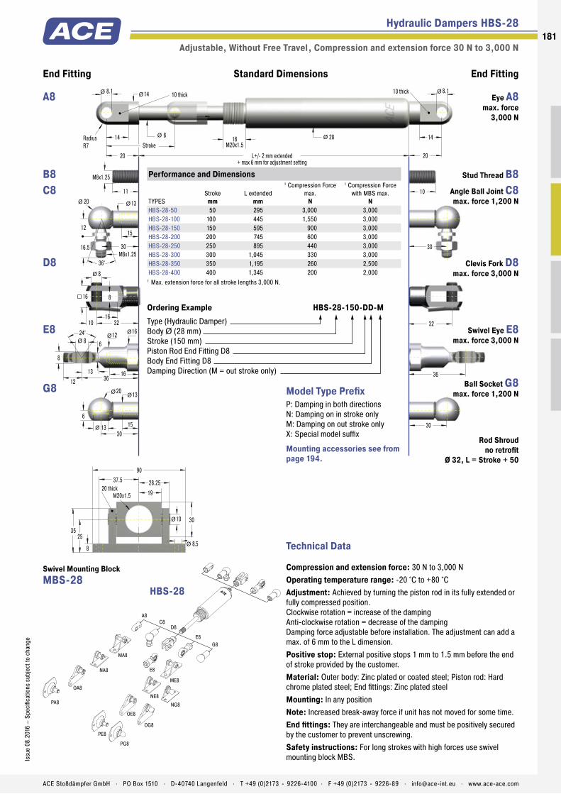
Piston Rod
Main Bearing
Balance Chamber
Outer Body
Piston
Seal
Pressure Chamber
Intermediate Bearing and Fixed Separator
Thread for End Fittings
Tooth Adjustment
Metering Orifice
Hydraulic Dampers HBS-28
Adjustable, Without Free Travel , Compression and extension force 30 N to 3,000 N
End Fitting End FittingStandard Dimensions
30
36
32
30
6
20 13
1513
24° 12 8
8
8
16
8
10 32
16
11
M8x1.25
30
14
14
20 L+/- 2 mm extended+ max 6 mm for adjustment setting
8
8.1
StrokeRadiusR7
10 thick
20
10 thick
28 14
30M8x1.25
12
20 13
15
16.5
36°
16
16
6
12 3613
Ø
Ø Ø
ØØ
Ø
Ø Ø
Ø
ØØ
Ø Ø
10
8.1
Ø
16M20x1.5
35
30
8.525
8
M20x1.5 19
90
28.2537.5
10
20 thick
Ø
Ø
A8
MA8
ME8
NG8
NA8
OG8
OA8
PA8
PG8
C8D8
E8G8
NE8
OE8
PE8
E8
Technical Data
Compression and extension force: 30 N to 3,000 NOperating temperature range: -20 °C to +80 °CAdjustment: Achieved by turning the piston rod in its fully extended or fully compressed position.Clockwise rotation = increase of the dampingAnti-clockwise rotation = decrease of the dampingDamping force adjustable before installation. The adjustment can add a max. of 6 mm to the L dimension.Positive stop: External positive stops 1 mm to 1.5 mm before the end of stroke provided by the customer.Material: Outer body: Zinc plated or coated steel; Piston rod: Hard chrome plated steel; End fi ttings: Zinc plated steelMounting: In any positionNote: Increased break-away force if unit has not moved for some time.End fi ttings: They are interchangeable and must be positively secured by the customer to prevent unscrewing.Safety instructions: For long strokes with high forces use swivel mounting block MBS.
Model Type Prefi xP: Damping in both directionsN: Damping on in stroke onlyM: Damping on out stroke onlyX: Special model suffi x
Performance and Dimensions
TYPESStroke
mmL extended
mm
1 Compression Force max.
N
1 Compression Force with MBS max.
NHBS-28-50 50 295 3,000 3,000HBS-28-100 100 445 1,550 3,000HBS-28-150 150 595 900 3,000HBS-28-200 200 745 600 3,000HBS-28-250 250 895 440 3,000HBS-28-300 300 1,045 330 3,000HBS-28-350 350 1,195 260 2,500HBS-28-400 400 1,345 200 2,000
1 Max. extension force for all stroke lengths 3,000 N.
Ordering Example HBS-28-150-DD-MType (Hydraulic Damper)Body Ø (28 mm)Stroke (150 mm)Piston Rod End Fitting D8Body End Fitting D8Damping Direction (M = out stroke only)
HBS-28
Mounting accessories see from page 194.
Eye A8 max. force
3,000 N
A8
Stud Thread B8 B8Angle Ball Joint C8 max. force 1,200 N
C8
Clevis Fork D8 max. force 3,000 N
D8
Swivel Eye E8 max. force 3,000 N
E8
Ball Socket G8 max. force 1,200 N G8
Swivel Mounting Block MBS-28
Rod Shroud no retrofi t
Ø 32, L = Stroke + 50
181Is
sue
08.2
016
– Sp
ecifi
catio
ns s
ubje
ct to
cha
nge
ACE Stoßdämpfer GmbH . PO Box 1510 . D-40740 Langenfeld . T +49 (0)2173 - 9226-4100 . F +49 (0)2173 - 9226-89 . [email protected] . www.ace-ace.com
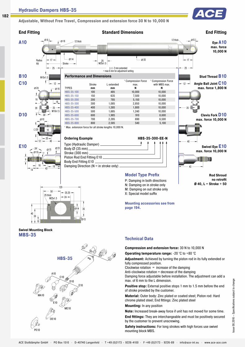
Hydraulic Dampers HBS-35
Adjustable, Without Free Travel , Compression and extension force 30 N to 10,000 N
End Fitting End FittingStandard Dimensions
43
40
24° 15 10
9
10
20
10
12 40
20
12
M10x1.5
35
18
17
25 L+/- 2 mm extended+ max 6 mm for adjustment setting
14
8.1
StrokeRadiusR9
12 thick
25
12 thick
35 17
35M10x1.5
16
24 16
18
20
36°
18
19
7
14 4316
Ø
Ø Ø
Ø Ø
Ø
ØØ
Ø Ø
12
8.1
Ø
25M25x1.5
40
35
1330
10
M25x1.5 24
120
35.2550
14
25 thick
Ø
Ø
A10
MA10
ME10
C10D10
E10
OE10
PE10
E10
Technical Data
Compression and extension force: 30 N to 10,000 NOperating temperature range: -20 °C to +80 °CAdjustment: Achieved by turning the piston rod in its fully extended or fully compressed position. Clockwise rotation = increase of the damping Anti-clockwise rotation = decrease of the damping Damping force adjustable before installation. The adjustment can add a max. of 6 mm to the L dimension.Positive stop: External positive stops 1 mm to 1.5 mm before the end of stroke provided by the customer.Material: Outer body: Zinc plated or coated steel; Piston rod: Hard chrome plated steel; End fittings: Zinc plated steelMounting: In any positionNote: Increased break-away force if unit has not moved for some time.End fittings: They are interchangeable and must be positively secured by the customer to prevent unscrewing.Safety instructions: For long strokes with high forces use swivel mounting block MBS.
Model Type PrefixP: Damping in both directionsN: Damping on in stroke onlyM: Damping on out stroke onlyX: Special model suffix
Performance and Dimensions
TYPESStroke
mmL extended
mm
1 Compression Force max.
N
1 Compression Force with MBS max.
NHBS-35-100 100 485 10,000 10,000HBS-35-150 150 635 7,500 10,000HBS-35-200 200 785 5,150 10,000HBS-35-300 300 1,085 2,850 10,000HBS-35-400 400 1,385 1,800 10,000HBS-35-500 500 1,685 1,240 10,000HBS-35-600 600 1,985 910 8,600HBS-35-700 700 2,285 690 6,500HBS-35-800 800 2,585 540 5,100
1 Max. extension force for all stroke lengths 10,000 N.
Ordering Example HBS-35-300-EE-NType (Hydraulic Damper)Body Ø (35 mm)Stroke (300 mm)Piston Rod End Fitting E10Body End Fitting E10Damping Direction (N = in stroke only)
HBS-35
Mounting accessories see from page 194.
Eye A10 max. force
10,000 N
A10
Stud Thread B10 B10Angle Ball Joint C10
max. force 1,800 N C10
Clevis Fork D10 max. force 10,000 N
D10
Swivel Eye E10 max. force 10,000 N
E10
Swivel Mounting Block MBS-35
Rod Shroud no retrofit
Ø 40, L = Stroke + 50
182
Issu
e 08
.201
6 –
Spec
ifica
tions
sub
ject
to c
hang
e
ACE Stoßdämpfer GmbH . PO Box 1510 . D-40740 Langenfeld . T +49 (0)2173 - 9226-4100 . F +49 (0)2173 - 9226-89 . [email protected] . www.ace-ace.com
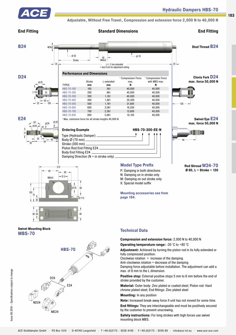
Hydraulic Dampers HBS-70
Adjustable, Without Free Travel , Compression and extension force 2,000 N to 40,000 N
End Fitting End FittingStandard Dimensions
100
25
50
25
32 100
50
Ø
94
30° 34 25
31
35 L+/- 2 mm extended+ max 8 mm for adjustment setting
30
Stroke
M24x2
35
70
40
42
22
30 9430
Ø Ø
ØØØ
40M64x2
100
80
17.575
20
M64x2 51.5
210
6990
25Ø
Ø
80 50 40
D24
E24
ME24
ND24
Technical Data
Compression and extension force: 2,000 N to 40,000 NOperating temperature range: -20 °C to +80 °CAdjustment: Achieved by turning the piston rod in its fully extended or fully compressed position. Clockwise rotation = increase of the damping Anti-clockwise rotation = decrease of the damping Damping force adjustable before installation. The adjustment can add a max. of 8 mm to the L dimension.Positive stop: External positive stops 5 mm to 6 mm before the end of stroke provided by the customer.Material: Outer body: Zinc plated or coated steel; Piston rod: Hard chrome plated steel; End fittings: Zinc plated steelMounting: In any positionNote: Increased break-away force if unit has not moved for some time.End fittings: They are interchangeable and must be positively secured by the customer to prevent unscrewing.Safety instructions: For long strokes with high forces use swivel mounting block MBS.
Model Type PrefixP: Damping in both directionsN: Damping on in stroke onlyM: Damping on out stroke onlyX: Special model suffix
Performance and Dimensions
TYPESStroke
mmL extended
mm
1 Compression Force max.
N
1 Compression Force with MBS max.
NHBS-70-100 100 561 40,000 40,000HBS-70-200 200 861 40,000 40,000HBS-70-300 300 1,161 40,000 40,000HBS-70-400 400 1,461 30,300 40,000HBS-70-500 500 1,761 21,600 40,000HBS-70-600 600 2,061 16,200 40,000HBS-70-700 700 2,361 12,600 40,000HBS-70-800 800 2,661 10,100 40,000
1 Max. extension force for all stroke lengths 40,000 N.
Ordering Example HBS-70-300-EE-NType (Hydraulic Damper)Body Ø (70 mm)Stroke (300 mm)Piston Rod End Fitting E24Body End Fitting E24Damping Direction (N = in stroke only)
HBS-70
Mounting accessories see from page 194.
Stud Thread B24 B24
Clevis Fork D24 max. force 50,000 N
D24
Swivel Eye E24 max. force 50,000 N
E24
Swivel Mounting Block MBS-70
Rod Shroud W24-70 Ø 80, L = Stroke + 130
183Is
sue
08.2
016
– Sp
ecifi
catio
ns s
ubje
ct to
cha
nge
ACE Stoßdämpfer GmbH . PO Box 1510 . D-40740 Langenfeld . T +49 (0)2173 - 9226-4100 . F +49 (0)2173 - 9226-89 . [email protected] . www.ace-ace.com

Piston Rod
Main Bearing
Pressure Chamber
Outer Body
Seal
Piston
Thread for End Fittings
Metering Orifice
Technical Data
High quality and long service life: The HB model of hydraulic damper can also be used as single or double acting brake. Its coated body in a slim gas spring design and the piston rods with wear-resistant surface coating are features of high quality and long service life.
The maintenance free, ready-to-install and closed systems provide a constant feed rate and are adjustable, and the control segment on the piston makes adjustment at the end position child’s play. Thanks to many add-on components the assembly is easy to mount, so that the damper can be universally deployed for damping back and forth swinging masses, such as in power or free conveyors.
On automotive or industrial applications, mechanical engineering, medical technology or the electronics and furniture industry, these machine elements are found in a number of different areas.
HB-12 to HB-70Hydraulic Dampers Linear motion control
Hydraulic Dampers
Adjustable
Compression and extension force: 20 N to 50,000 NOuter body diameter: Ø 12 mm to Ø 70 mmPiston rod diameter: Ø 4 mm to Ø 30 mmLifetime: Approx. 10,000 mFree travel: Construction of the damper results in a free travel of approx. 20 % of stroke.Separator piston: Available as a special option without free travel achieved by separator piston and nitrogen accumulator.Operating temperature range: -20 °C to +80 °C
Adjustment: Achieved by turning the piston rod in its fully extended or fully compressed position.Positive stop: External positive stops 1 mm to 6 mm before the end of stroke provided by the customer.Damping medium: Hydraulic oilMaterial: Outer body: Coated steel; Piston rod: Steel or stainless steel with wear-resistant coating; End fi ttings: Zinc plated steelMounting: In any position
Application fi eld: Conveyor systems, Transport systems, Furniture industry, Locking systemsNote: Increased break-away force if unit has not moved for some time.End fi ttings: They are interchangeable and must be positively secured by the customer to prevent unscrewing.On request: Special oils and other special options. Alternative accessories available on request.
184
Issu
e 08
.201
6 –
Spec
ifi ca
tions
sub
ject
to c
hang
e
ACE Stoßdämpfer GmbH . PO Box 1510 . D-40740 Langenfeld . T +49 (0)2173 - 9226-4100 . F +49 (0)2173 - 9226-89 . [email protected] . www.ace-ace.com

Piston Rod
Main Bearing
Pressure Chamber
Outer Body
Seal
Piston
Thread for End Fittings
Metering Orifice
Hydraulic Dampers HB-12
Adjustable , Compression and extension force 20 N to 180 N
12
End Fitting End FittingStandard Dimensions
24° 7.8 4
5
5.3
7 127.3
ØØ
7
1818
4
13 8
68
5
M3.5x0.6
18
8
8
12 L+/- 2 mm extended
4
4.1
StrokeRadiusR4
4 thick
12
4 thick
12 8
L = Stroke + 10
15
ØØ
Ø
Ø Ø
ØØ
4
8
4
5 16
8
Ø
Ø
Ø
18M4x0.7
8.5
13 8
6
10
36°
Ø Ø
5
4.1
16
A3,5
NG3,5
NA3,5
OG3,5
OA3,5
C3,5D3,5
E3,5G3,5
A3,5
Technical Data
Compression and extension force: 20 N to 180 NFree travel: Construction of the damper results in a free travel of approx. 21 % of stroke.Separator piston: -Operating temperature range: -20 °C to +80 °CAdjustment: Achieved by turning the piston rod in its fully extended or fully compressed position. Clockwise rotation = increase of the dampingAnti-clockwise rotation = decrease of the damping. The adjustment can add a max. of 6 mm to the L dimension.Positive stop: External positive stops 1 mm to 1.5 mm before the end of stroke provided by the customer.Material: Outer body: Coated steel; Piston rod: Stainless steel (1.4301/1.4305, AISI 304/303); End fi ttings: Zinc plated steelMounting: In any positionNote: Increased break-away force if unit has not moved for some time.End fi ttings: They are interchangeable and must be positively secured by the customer to prevent unscrewing.
Model Type Prefi xP: Damping in both directionsN: Damping on in stroke onlyM: Damping on out stroke onlyX: Special model suffi x
Performance and Dimensions
TYPESStroke
mmL extended
mm1 Compression Force max.
NHB-12-10 10 55 180HB-12-20 20 75 180HB-12-30 30 95 180HB-12-40 40 115 180HB-12-50 50 135 180HB-12-60 60 155 180HB-12-70 70 175 180HB-12-80 80 195 150
1 Max. extension force for all stroke lengths 180 N.
Ordering Example HB-12-30-AC-MType (Hydraulic Damper)Body Ø (12 mm)Stroke (30 mm)Piston Rod End Fitting A3,5Body End Fitting C3,5Damping Direction (M = out stroke only)
HB-12
Mounting accessories see from page 194.
Eye A3,5 max. force 370 N
A3,5
Stud Thread B3,5 B3,5
Angle Ball Joint C3,5 max. force 370 N
C3,5
Clevis Fork D3,5 max. force 370 N
D3,5
Swivel Eye E3,5 max. force 370 N
E3,5
Ball Socket G3,5 max. force 370 N
G3,5
Rod Shroud W3,5-12
185Is
sue
08.2
016
– Sp
ecifi
catio
ns s
ubje
ct to
cha
nge
ACE Stoßdämpfer GmbH . PO Box 1510 . D-40740 Langenfeld . T +49 (0)2173 - 9226-4100 . F +49 (0)2173 - 9226-89 . [email protected] . www.ace-ace.com
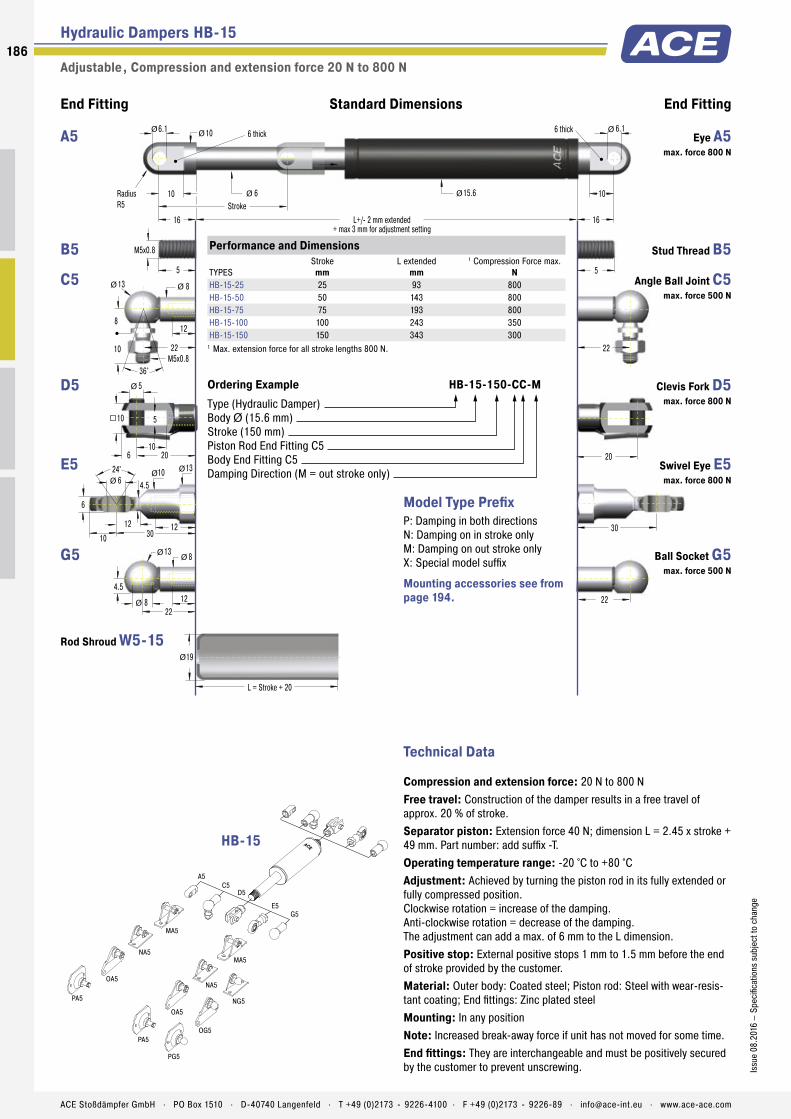
Hydraulic Dampers HB-15
Adjustable , Compression and extension force 20 N to 800 N
End Fitting End FittingStandard Dimensions
22
30
20
22
4.5
13 8
128
24° 10 6
6
5
10
5
6 20
10
5
M5x0.8
22
10
10
16 L+/- 2 mm extended+ max 3 mm for adjustment setting
6
6.1
StrokeRadiusR5
6 thick
16
6 thick
15.6 10
L = Stroke + 20
19
22M5x0.8
8
13 8
12
10
36°
12
13
4.5
10 3012
Ø
Ø Ø
ØØ
Ø
Ø Ø
Ø
ØØ
Ø
Ø
Ø
5
6.1
Ø
A5
MA5
MA5
NG5
NA5
OG5
OA5
PA5
PG5
C5D5
E5G5
NA5
OA5
PA5
Technical Data
Compression and extension force: 20 N to 800 NFree travel: Construction of the damper results in a free travel of approx. 20 % of stroke.Separator piston: Extension force 40 N; dimension L = 2.45 x stroke + 49 mm. Part number: add suffix -T.Operating temperature range: -20 °C to +80 °CAdjustment: Achieved by turning the piston rod in its fully extended or fully compressed position. Clockwise rotation = increase of the damping. Anti-clockwise rotation = decrease of the damping. The adjustment can add a max. of 6 mm to the L dimension.Positive stop: External positive stops 1 mm to 1.5 mm before the end of stroke provided by the customer.Material: Outer body: Coated steel; Piston rod: Steel with wear-resis-tant coating; End fittings: Zinc plated steelMounting: In any positionNote: Increased break-away force if unit has not moved for some time.End fittings: They are interchangeable and must be positively secured by the customer to prevent unscrewing.
Model Type PrefixP: Damping in both directionsN: Damping on in stroke onlyM: Damping on out stroke onlyX: Special model suffix
Performance and Dimensions
TYPESStroke
mmL extended
mm1 Compression Force max.
NHB-15-25 25 93 800HB-15-50 50 143 800HB-15-75 75 193 800HB-15-100 100 243 350HB-15-150 150 343 300
1 Max. extension force for all stroke lengths 800 N.
Ordering Example HB-15-150-CC-MType (Hydraulic Damper)Body Ø (15.6 mm)Stroke (150 mm)Piston Rod End Fitting C5Body End Fitting C5Damping Direction (M = out stroke only)
HB-15
Mounting accessories see from page 194.
Eye A5 max. force 800 N
A5
Stud Thread B5 B5
Angle Ball Joint C5 max. force 500 N
C5
Clevis Fork D5 max. force 800 N
D5
Swivel Eye E5 max. force 800 N
E5
Ball Socket G5 max. force 500 N
G5
Rod Shroud W5-15
186
Issu
e 08
.201
6 –
Spec
ifica
tions
sub
ject
to c
hang
e
ACE Stoßdämpfer GmbH . PO Box 1510 . D-40740 Langenfeld . T +49 (0)2173 - 9226-4100 . F +49 (0)2173 - 9226-89 . [email protected] . www.ace-ace.com
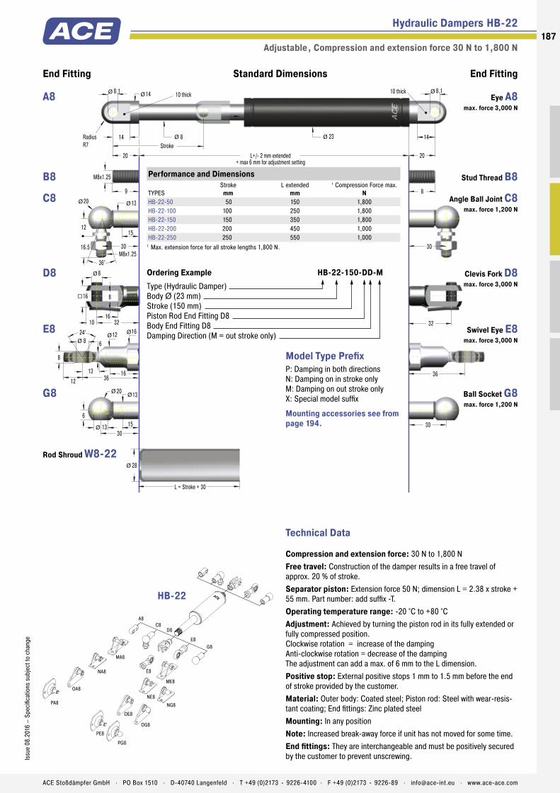
Hydraulic Dampers HB-22
Adjustable , Compression and extension force 30 N to 1,800 N
End Fitting End FittingStandard Dimensions
30
36
32
30
6
20 13
1513
24° 12 8
8
8
16
8
10 32
16
9
M8x1.25
30
14
14
20 L+/- 2 mm extended+ max 6 mm for adjustment setting
8
8.1
StrokeRadiusR7
10 thick
20
10 thick
23 14
L = Stroke + 30
28
30M8x1.25
12
20 13
15
16.5
36°
16
16
6
12 3613
Ø
Ø Ø
ØØ
Ø
Ø Ø
Ø
ØØ
Ø
Ø
Ø
8
8.1
Ø
A8
MA8
ME8
NG8
NA8
OG8
OA8
PA8
PG8
C8D8
E8G8
NE8
OE8
PE8
E8
Technical Data
Compression and extension force: 30 N to 1,800 NFree travel: Construction of the damper results in a free travel of approx. 20 % of stroke.Separator piston: Extension force 50 N; dimension L = 2.38 x stroke + 55 mm. Part number: add suffix -T.Operating temperature range: -20 °C to +80 °CAdjustment: Achieved by turning the piston rod in its fully extended or fully compressed position. Clockwise rotation = increase of the damping Anti-clockwise rotation = decrease of the damping The adjustment can add a max. of 6 mm to the L dimension.Positive stop: External positive stops 1 mm to 1.5 mm before the end of stroke provided by the customer.Material: Outer body: Coated steel; Piston rod: Steel with wear-resis-tant coating; End fittings: Zinc plated steelMounting: In any positionNote: Increased break-away force if unit has not moved for some time.End fittings: They are interchangeable and must be positively secured by the customer to prevent unscrewing.
Model Type PrefixP: Damping in both directionsN: Damping on in stroke onlyM: Damping on out stroke onlyX: Special model suffix
Performance and Dimensions
TYPESStroke
mmL extended
mm1 Compression Force max.
NHB-22-50 50 150 1,800HB-22-100 100 250 1,800HB-22-150 150 350 1,800HB-22-200 200 450 1,000HB-22-250 250 550 1,000
1 Max. extension force for all stroke lengths 1,800 N.
Ordering Example HB-22-150-DD-MType (Hydraulic Damper)Body Ø (23 mm)Stroke (150 mm)Piston Rod End Fitting D8Body End Fitting D8Damping Direction (M = out stroke only)
HB-22
Mounting accessories see from page 194.
Eye A8 max. force 3,000 N
A8
Stud Thread B8 B8
Angle Ball Joint C8 max. force 1,200 N
C8
Clevis Fork D8 max. force 3,000 N
D8
Swivel Eye E8 max. force 3,000 N
E8
Ball Socket G8 max. force 1,200 N
G8
Rod Shroud W8-22
187Is
sue
08.2
016
– Sp
ecifi
catio
ns s
ubje
ct to
cha
nge
ACE Stoßdämpfer GmbH . PO Box 1510 . D-40740 Langenfeld . T +49 (0)2173 - 9226-4100 . F +49 (0)2173 - 9226-89 . [email protected] . www.ace-ace.com

Hydraulic Dampers HB-28
Adjustable , Compression and extension force 30 N to 3,000 N
End Fitting End FittingStandard Dimensions
30
36
32
30
6
20 13
1513
24° 12 8
8
8
16
8
10 32
16
9
M8x1.25
30
14
14
20 L+/- 2 mm extended+ max 6 mm for adjustment setting
10
8.1
StrokeRadiusR7
10 thick
20
10 thick
28 14
L = Stroke + 40
32
30M8x1.25
12
20 13
15
16.5
36°
16
16
6
12 3613
Ø
Ø Ø
ØØ
Ø
Ø Ø
Ø
ØØ
Ø
Ø
Ø
8
8.1
Ø
A8
MA8
ME8
NG8
NA8
OG8
OA8
PA8
PG8
C8D8
E8G8
NE8
OE8
PE8
E8
Technical Data
Compression and extension force: 30 N to 3,000 NFree travel: Construction of the damper results in a free travel of approx. 20 % of stroke.Separator piston: Extension force 80 N; dimension L = 2.35 x stroke + 60 mm. Part number: add suffix -T.Operating temperature range: -20 °C to +80 °CAdjustment: Achieved by turning the piston rod in its fully extended or fully compressed position. Clockwise rotation = increase of the damping Anti-clockwise rotation = decrease of the damping The adjustment can add a max. of 6 mm to the L dimension.Positive stop: External positive stops 1 mm to 1.5 mm before the end of stroke provided by the customer.Material: Outer body: Coated steel; Piston rod: Steel with wear-resis-tant coating; End fittings: Zinc plated steelMounting: In any positionNote: Increased break-away force if unit has not moved for some time.End fittings: They are interchangeable and must be positively secured by the customer to prevent unscrewing.
Model Type PrefixP: Damping in both directionsN: Damping on in stroke onlyM: Damping on out stroke onlyX: Special model suffix
Performance and Dimensions
TYPESStroke
mmL extended
mm1 Compression Force max.
NHB-28-100 100 260 3,000HB-28-150 150 360 3,000HB-28-200 200 460 3,000HB-28-250 250 560 3.000HB-28-300 300 660 2,500HB-28-350 350 760 2,000HB-28-400 400 860 1,500HB-28-500 500 1,060 1,000
1 Max. extension force for all stroke lengths 3,000 N.
Ordering Example HB-28-150-DD-MType (Hydraulic Damper)Body Ø (28 mm)Stroke (150 mm)Piston Rod End Fitting D8Body End Fitting D8Damping Direction (M = out stroke only)
HB-28
Mounting accessories see from page 194.
Eye A8 max. force 3,000 N
A8
Stud Thread B8 B8
Angle Ball Joint C8 max. force 1,200 N
C8
Clevis Fork D8 max. force 3,000 N
D8
Swivel Eye E8 max. force 3,000 N
E8
Ball Socket G8 max. force 1,200 N
G8
Rod Shroud W8-28
188
Issu
e 08
.201
6 –
Spec
ifica
tions
sub
ject
to c
hang
e
ACE Stoßdämpfer GmbH . PO Box 1510 . D-40740 Langenfeld . T +49 (0)2173 - 9226-4100 . F +49 (0)2173 - 9226-89 . [email protected] . www.ace-ace.com

Hydraulic Dampers HB-40
Adjustable , Compression and extension force 30 N to 10,000 N
End Fitting End FittingStandard Dimensions
15
M14x1.5
45
25
21
40 L+/- 2 mm extended+ max 6 mm for adjustment setting
14
14.1
StrokeRadiusR12.5
14 thick
40
14 thick
40 21
L = Stroke + 40
45
Ø Ø
Ø
57
Ø
14
27
14
16 56
27
Ø
Ø
Ø
45M14x1.5
20
30 22
25
28
36°
Ø Ø
15
14.1
56
30° 20 14
19
30
26
13
18 5718
ØØ
Ø
A14C14
D14
E14
ME14
ME14
ND14
Technical Data
Compression and extension force: 30 N to 10,000 NFree travel: Construction of the damper results in a free travel of approx. 20 % of stroke.Separator piston: Extension force 150 N; dimension L = 2.32 x stroke + 82 mm. Part number: add suffix -T.Operating temperature range: -20 °C to +80 °CAdjustment: Achieved by turning the piston rod in its fully extended or fully compressed position. Clockwise rotation = increase of the damping Anti-clockwise rotation = decrease of the damping The adjustment can add a max. of 6 mm to the L dimension.Positive stop: External positive stops 1 mm to 1.5 mm before the end of stroke provided by the customer.Material: Outer body: Coated steel; Piston rod: Steel with wear-resis-tant coating; End fittings: Zinc plated steelMounting: In any positionNote: Increased break-away force if unit has not moved for some time.End fittings: They are interchangeable and must be positively secured by the customer to prevent unscrewing.
Model Type PrefixP: Damping in both directionsN: Damping on in stroke onlyM: Damping on out stroke onlyX: Special model suffix
Performance and Dimensions
TYPESStroke
mmL extended
mm1 Compression Force max.
NHB-40-100 100 275 10,000HB-40-150 150 375 10,000HB-40-200 200 475 10,000HB-40-300 300 675 10,000HB-40-400 400 875 8,000HB-40-500 500 1,075 6,000HB-40-600 600 1,275 4,000HB-40-700 700 1,475 3,000HB-40-800 800 1,675 3,000
1 Max. extension force for all stroke lengths 10,000 N.
Ordering Example HB-40-300-EE-NType (Hydraulic Damper)Body Ø (40 mm)Stroke (300 mm)Piston Rod End Fitting E14Body End Fitting E14Damping Direction (N = in stroke only)
HB-40
Mounting accessories see from page 194.
Eye A14 max. force 10,000 N
A14
Stud Thread B14 B14
Angle Ball Joint C14 max. force 3,200 N
C14
Clevis Fork D14 max. force 10,000 N
D14
Swivel Eye E14 max. force 10,000 N
E14
Rod Shroud W14-40
189Is
sue
08.2
016
– Sp
ecifi
catio
ns s
ubje
ct to
cha
nge
ACE Stoßdämpfer GmbH . PO Box 1510 . D-40740 Langenfeld . T +49 (0)2173 - 9226-4100 . F +49 (0)2173 - 9226-89 . [email protected] . www.ace-ace.com

Hydraulic Dampers HB-70
Adjustable , Compression and extension force 2,000 N to 50,000 N
End Fitting End FittingStandard Dimensions
35 L+/- 2 mm extended+ max 8 mm for adjustment setting
30
Stroke35
70
L = Stroke + 130
80
ØØ
94
25
50
25
32 100
50
Ø
Ø
100
30° 34 25
31
40
42
22
30 9430
ØØ
Ø
M24x2
D24
E24
ME24
ND24
Technical Data
Compression and extension force: 2,000 N to 50,000 NFree travel: Construction of the damper results in a free travel of approx. 20 % of stroke.Separator piston: Extension force min. 250 N; dimension L + 150 mm. Part number: add suffix -T.Operating temperature range: -20 °C to +80 °CAdjustment: Achieved by turning the piston rod in its fully extended or fully compressed position. Clockwise rotation = increase of the damping Anti-clockwise rotation = decrease of the damping The adjustment can add a max. of 8 mm to the L dimension.Positive stop: External positive stops 5 mm to 6 mm before the end of stroke provided by the customer.Material: Outer body: Coated steel; Piston rod: Hard chrome plated steel; End fittings: Zinc plated steelMounting: In any positionNote: Increased break-away force if unit has not moved for some time.End fittings: They are interchangeable and must be positively secured by the customer to prevent unscrewing.
Model Type PrefixP: Damping in both directionsN: Damping on in stroke onlyM: Damping on out stroke onlyX: Special model suffix
Performance and Dimensions
TYPESStroke
mmL extended
mm1 Compression Force max.
NHB-70-100 100 320 50,000HB-70-200 200 520 50,000HB-70-300 300 720 50,000HB-70-400 400 920 30,300HB-70-500 500 1,120 21,600HB-70-600 600 1,320 16,200HB-70-700 700 1,520 12,600HB-70-800 800 1,720 10,100
1 Max. extension force for all stroke lengths 50,000 N.
Ordering Example HB-70-300-EE-NType (Hydraulic Damper)Body Ø (70 mm)Stroke (300 mm)Piston Rod End Fitting E24 Body End Fitting E24Damping Direction (N = in stroke only)
HB-70
Mounting accessories see from page 194.
Stud Thread B24 B24
Clevis Fork D24 max. force 50,000 N
D24
Swivel Eye E24 max. force 50,000 N
E24
Rod Shroud W24-70
190
Issu
e 08
.201
6 –
Spec
ifica
tions
sub
ject
to c
hang
e
ACE Stoßdämpfer GmbH . PO Box 1510 . D-40740 Langenfeld . T +49 (0)2173 - 9226-4100 . F +49 (0)2173 - 9226-89 . [email protected] . www.ace-ace.com

Technical Data
Door Dampers
Adjustable
Outer body diameter: Ø 28 mmPiston rod diameter: Ø 8 mmFree travel: TDE: MarginalOperating temperature range: -20 °C to 80 °CAdjustment: Pull the piston rod fully out and turn the knurled rod end button. The internal toothed adjustment allows the damping to be
separately adjusted for each side. As a result of the adjustment mechanism the overall length L can be increased by up to 4 mm.Material: Outer body: Zinc plated steel; Piston rod: Hard chrome plated steelImpact velocity range: 0.1 m/s to 2 m/sStrokes per minute: Max. 10
Application field: Lift doors, Automatic doors, DoorsNote: ACE door dampers are single ended or double ended adjustable hydraulic shock absorbers.On request: Special oils, other special options and special accessories are available on request.
28
C +/- 2 mm14
23
25
8M16x1
Stroke A 14
23
M16x18
25L extended
+ max 8 mm for adjustment setting
Stroke B
Ø
Ø
ØØ
Ø
TD-28
Performance and Dimensions
TYPESEnergy Capacity
Nm/cycleReacting Force
NImpact Mass max.
kgStroke A
mmStroke B
mmC
mmL extended
mmReturn Force max.
N1 Return Type
TD-28-50-50-F 75 1,550 150 50 50 220 402 30 FTD-28-70-70-F 70 1,500 200 70 70 260 482 30 FTD-28-100-100-F 80 1,500 250 100 100 220 502 40 FTD-28-120-120-D 165 3,800 250 120 120 208 410 - D
1 Standard model. Other models available on request.
Ordering Example TD-28-50-50Type (Door Damper)Body Ø (28 mm)Stroke A (50 mm)Stroke B (50 mm)
Model Type PrefixF: Automatic return with return springD: Without return spring. When one piston is pushed in, the piston rod at the other end is pushed out (thus the damper must be impacted from alternate ends to sequence correctly).
28
C +/- 2 mm14
23
25
8M16x1
StrokeL +/- 2 mm extended
+ max 4 mm for adjustment setting
Ø
ØØ
TDE-28
Performance and Dimensions
TYPESEnergy Capacity
Nm/cycleReacting Force
NImpact Mass max.
kgStroke
mmC
mmL extended
mmReturn Force max.
NTDE-28-50 80 2,400 4,000 50 130 221 30TDE-28-70 112 2,400 5,600 70 158 269 30TDE-28-100 160 2,400 8,000 100 193 333 30TDE-28-120 190 2,400 7,000 120 214 373 40
Ordering Example TDE-28-50Type (Door Damper)Body Ø (28 mm)Stroke (50 mm)
MB-16 Clamp Mount
Ø 28.5
M5x40DIN 4762
M16x135
35 30
15
191Is
sue
08.2
016
– Sp
ecifi
catio
ns s
ubje
ct to
cha
nge
ACE Stoßdämpfer GmbH . PO Box 1510 . D-40740 Langenfeld . T +49 (0)2173 - 9226-4100 . F +49 (0)2173 - 9226-89 . [email protected] . www.ace-ace.com

Application Examples
Hydraulic Dampers
DVC-32
Precise unreelingHydraulic dampers bring the sled movement of this textile machine to a gentle stop. At the turning point of 130 kg reeling spools, a sled should move up and down smoothly without causing a collision at the end of stroke position. The solution was provided by the hydraulic damper DVC-32-100EU. A self-contained sealed unit, ready to install and maintenance-free these units are ideal for precise control of speeds in both directions of travel. The travel speed is maintained throughout the entire stroke and can be independently adjusted in each direction of travel. Thanks to their compact design and wide choice of mounting accessories, these dampers could be easily integrated into this machine.
Textile machine unreels threads even better
HB-15
Operating speed of fl aps top-regulatedIn the past, operators of used-clothes containers could sustain injury because the fl aps closed relatively quickly and uncontrollably. Various hydraulic dampers of the type HB-15, which are designed specifi cally for the type of container, regulate the synchronization of the fl ap in both directions and thereby serve to regulate the operating speed. To accommodate a range of requirements and to provide optimal protection against theft, different types with different strokes are mounted on fl aps without damping, on large fl aps with damping and on rotor fl aps with damping.
Hydraulic dampers prevent fi ngers becoming trapped in used-clothes containers as they ensure more gentle opening and closing movements MCB Milieu & Techniek BV, 4704 SE Roosendaal, Netherlands
192
Issu
e 08
.201
6 –
Spec
ifi ca
tions
sub
ject
to c
hang
e
ACE Stoßdämpfer GmbH . PO Box 1510 . D-40740 Langenfeld . T +49 (0)2173 - 9226-4100 . F +49 (0)2173 - 9226-89 . [email protected] . www.ace-ace.com
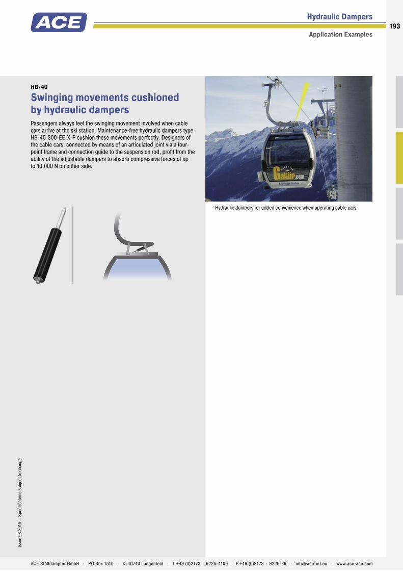
Hydraulic Dampers
Application Examples
HB-40
Swinging movements cushioned by hydraulic dampersPassengers always feel the swinging movement involved when cable cars arrive at the ski station. Maintenance-free hydraulic dampers type HB-40-300-EE-X-P cushion these movements perfectly. Designers of the cable cars, connected by means of an articulated joint via a four-point frame and connection guide to the suspension rod, profi t from the ability of the adjustable dampers to absorb compressive forces of up to 10,000 N on either side.
Hydraulic dampers for added convenience when operating cable cars
193Is
sue
08.2
016
– Sp
ecifi
catio
ns s
ubje
ct to
cha
nge
ACE Stoßdämpfer GmbH . PO Box 1510 . D-40740 Langenfeld . T +49 (0)2173 - 9226-4100 . F +49 (0)2173 - 9226-89 . [email protected] . www.ace-ace.com

By taking advantage of the very extensive range of ACE end fittings and mounting brackets you can easily and simply install our gas springs and hydraulic dampers. You profit from the variety of DIN Standard end fittings such as swivel eyes, clevis forks, angle ball joints, inline ball joints, and complementary ball sockets.
Mounting Accessories for gas springs and hydraulic dampers made of steel
Gas Springs and Hydraulic Dampers
ACE also offers eye fittings made of wear-resistant steel to meet the higher specification requirements found in industrial applications. With over 30 different types available these mounting accessories provide an extensive range of combinations for optimum installations.
With the ACE selection programme you can choose not only your ACE gas springs but also the ideal end fittings and mounting brackets for your individual application example.
The complete range of accessories are also available as individual components.
194194
ACE Stoßdämpfer GmbH . PO Box 1510 . D-40740 Langenfeld . T +49 (0)2173 - 9226-4100 . [email protected] . www.ace-ace.com
Individual
Combinations!

M3.5x0.6 (for GS-8, GS-10, GS-12, GZ-15, HB-12)
Steel Accessories for Gas Springs and Hydraulic Dampers
Overview
+
+
+
1 Attention! Max. static load in Newtons. Beware force increase during compression (progression) and observe max. force limit.
C3,5Angle Ball JointDIN 71802
18M4x0.7
8.5
13 8
6
10
36°
Ø Ø
M3.5
1 max. force 370 N
A3,5Eye
8
12
4.14 thick
M3.5
6
8Ø
RadiusR4
1 max. force 370 N
NA3,5Angle Bracket with Ball
8
163191.5
3.4
4
10ØØ
4
3.5 4.5
5.75 4.25
Ø
1 max. force 180 N
OA3,5Side Bracket with Ball
185
5
168
13
5
4.3Ø
Ø
41
21.5
4.5 4.5
Ø
1 max. force 180 N
D3,5Clevis ForkDIN 71752
4
8
4
5 16
8
Ø
M3.5
1 max. force 370 N
A3,5Eye
8
12
4.14 thick
M3.5
6
8Ø
RadiusR4
1 max. force 370 N
G3,5Ball SocketDIN 71805
18
4
13 8
68
ØØ
Ø
M3.5
1 max. force 370 N
NG3,5Angle Bracket with Ball
8
163191.5
3.4
4
10ØØ
8
12.5
4.5Ø
1 max. force 180 N
OG3,5Side Bracket with Ball
185
5
168
13
5
4.3Ø
Ø
8
5.5
13.5
Ø
1 max. force 180 N
E3,5Swivel EyeDIN 648
M3.5
24° 7.8 4
5
5.3
7 127.3
ØØ
7
1 max. force 370 N
195Is
sue
08.2
016
– Sp
ecifi
catio
ns s
ubje
ct to
cha
nge
ACE Stoßdämpfer GmbH . PO Box 1510 . D-40740 Langenfeld . T +49 (0)2173 - 9226-4100 . F +49 (0)2173 - 9226-89 . [email protected] . www.ace-ace.com
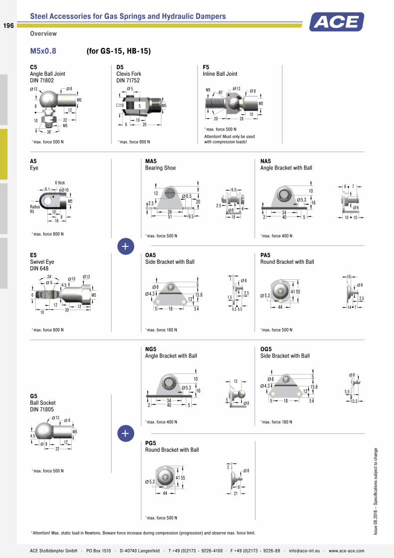
Steel Accessories for Gas Springs and Hydraulic Dampers
Overview
1 Attention! Max. static load in Newtons. Beware force increase during compression (progression) and observe max. force limit.
M5x0.8 (for GS-15, HB-15)
+
+
C5Angle Ball JointDIN 71802
22M5
8
13 8
12
10
36°
Ø Ø
M5
1 max. force 500 N
D5Clevis ForkDIN 71752
5
10
5
6 20
10
Ø
M5
1 max. force 800 N
F5Inline Ball Joint
1028
AF13
20
45°M5 8Ø
M5
1 max. force 500 N
Attention! Must only be used with compression loads!
A5Eye
10
16
6.16 thick
M5
8
10Ø
RadiusR5
1 max. force 800 N
MA5Bearing Shoe
369.551
2.56.513
20
9Ø
6
6.5
18
2.54Ø
1 max. force 500 N
NA5Angle Bracket with Ball
345402
5.3
10
16Ø
6
6 7
10 10
Ø
1 max. force 400 N
E5Swivel EyeDIN 648
24° 10 6
6
12
13
4.5
10 3012
ØØØ
M5
1 max. force 800 N
OA5Side Bracket with Ball
185
5
15.68
13
5
4.3Ø
Ø
61
2.51.5
6.5 6.5
Ø
1 max. force 180 N
PA5Round Bracket with Ball
44
55415.3Ø
6
10
2.5
14 7
Ø
1 max. force 500 N
NG5Angle Bracket with Ball
345402
5.3
10
16Ø
8
13
5Ø
1 max. force 400 N
OG5Side Bracket with Ball
185
5
15.68
13
5
4.3Ø
Ø
8
5.5
13.5
Ø
1 max. force 180 N
G5Ball SocketDIN 71805
22
4.5
13 8
128
ØØ
Ø
M5
1 max. force 500 N
PG5Round Bracket with Ball
44
55415.3Ø
8
218
2Ø
1 max. force 500 N
196
Issu
e 08
.201
6 –
Spec
ifica
tions
sub
ject
to c
hang
e
ACE Stoßdämpfer GmbH . PO Box 1510 . D-40740 Langenfeld . T +49 (0)2173 - 9226-4100 . F +49 (0)2173 - 9226-89 . [email protected] . www.ace-ace.com
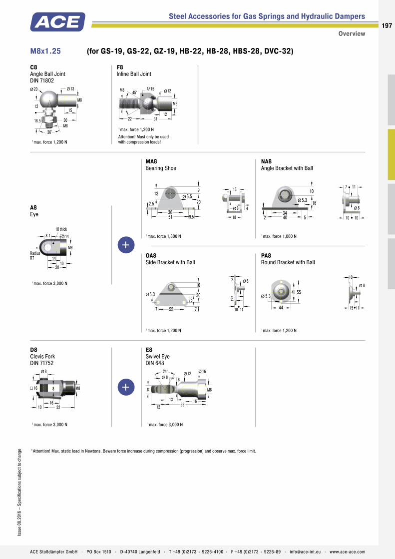
M8x1.25 (for GS-19, GS-22, GZ-19, HB-22, HB-28, HBS-28, DVC-32)
Steel Accessories for Gas Springs and Hydraulic Dampers
Overview
1 Attention! Max. static load in Newtons. Beware force increase during compression (progression) and observe max. force limit.
+
+
C8Angle Ball JointDIN 71802
30M8
12
20 13
15
16.5
36°
Ø Ø
M8
1 max. force 1,200 N
F8Inline Ball Joint
1231
AF15
22
45°M8 12Ø
M8
1 max. force 1,200 N
Attention! Must only be used with compression loads!
A8Eye
14
20
8.110 thick
M8
10
14Ø
RadiusR7
1 max. force 3,000 N
MA8Bearing Shoe
369.551
2.56.513
20
9Ø
18
8
13
4Ø
1 max. force 1,800 N
NA8Angle Bracket with Ball
345402
5.3
10
16Ø
8
7 11
10 10
Ø
1 max. force 1,000 N
OA8Side Bracket with Ball
557
10
3023
7
5.3Ø
82
3
10 11
Ø
1 max. force 1,200 N
PA8Round Bracket with Ball
44
55415.3Ø
8
10
15 11
Ø
1 max. force 1,200 N
D8Clevis ForkDIN 71752
8
16
8
10 32
16
Ø
M8
1 max. force 3,000 N
E8Swivel EyeDIN 648
24° 12 8
8
16
16
6
12 3613
ØØØ
M8
1 max. force 3,000 N
197Is
sue
08.2
016
– Sp
ecifi
catio
ns s
ubje
ct to
cha
nge
ACE Stoßdämpfer GmbH . PO Box 1510 . D-40740 Langenfeld . T +49 (0)2173 - 9226-4100 . F +49 (0)2173 - 9226-89 . [email protected] . www.ace-ace.com

Steel Accessories for Gas Springs and Hydraulic Dampers
Overview
1 Attention! Max. static load in Newtons. Beware force increase during compression (progression) and observe max. force limit.
M8x1.25 (for GS-19, GS-22, GZ-19, HB-22, HB-28, HBS-28, DVC-32)
+
+
E8Swivel EyeDIN 648
24° 12 8
8
16
16
6
12 3613
ØØØ
M8
1 max. force 3,000 N
ME8Bearing Shoe
369.551
2.56.513
20
9Ø
8
8
Ø
1 max. force 1,800 N
NE8Angle Bracket with Ball
345402
5.3
10
16Ø
8
7 8.5
Ø
1 max. force 1,000 N
OE8Side Bracket with Ball
557
10
3023
7
5.3Ø
8
53
10 8.5
Ø
1 max. force 1,200 N
PE8Round Bracket with Ball
44
55415.3Ø
8
2
5
15 8.5
Ø
1 max. force 1,200 N
NG8Angle Bracket with Ball
345402
5.3
10
16Ø
13
14.5
5Ø
1 max. force 1,000 N
OG8Side Bracket with Ball
557
10
3023
7
5.3Ø
13
8
17.5
Ø
1 max. force 1,200 N
G8Ball SocketDIN 71805
30
6
20 13
1513
ØØ
Ø
M8
1 max. force 1,200 N
PG8Round Bracket with Ball
44
55415.3Ø
13
22.5
9.5
Ø
1 max. force 1,200 N
198
Issu
e 08
.201
6 –
Spec
ifica
tions
sub
ject
to c
hang
e
ACE Stoßdämpfer GmbH . PO Box 1510 . D-40740 Langenfeld . T +49 (0)2173 - 9226-4100 . F +49 (0)2173 - 9226-89 . [email protected] . www.ace-ace.com

M10x1.5 (for GS-28, GZ-28, HBS-35)
+
+
+
Steel Accessories for Gas Springs and Hydraulic Dampers
Overview
1 Attention! Max. static load in Newtons. Beware force increase during compression (progression) and observe max. force limit.
C10Angle Ball JointDIN 71802
35M10
16
24 16
18
20
36°
Ø Ø
M10
1 max. force 1,800 N
F10Inline Ball Joint
1943
AF17
25
45°M10 AF17
M10
1 max. force 1,800 N
Attention! Must only be used with compression loads!
A10Eye
17
25
8.112 thick
M10
15
18Ø
RadiusR9
1 max. force 10,000 N
MA10Bearing Shoe
369.551
2.56.513
20
9Ø
18
8
13
4Ø
1 max. force 1,800 N
D10Clevis ForkDIN 71752
10
20
10
12 40
20
Ø
M10
1 max. force 10,000 N
E10Swivel EyeDIN 648
24° 15 10
9
18
19
7
14 4316
ØØØ
M10
1 max. force 10,000 N
ME10Bearing Shoe
369.551
2.56.513
20
9Ø
10
9
Ø
1 max. force 1,800 N
OE10Side Bracket with Ball
557
10
3016
23
7
5.3Ø
Ø
10
43
10 9
Ø2
1 max. force 1,200 N
E10Swivel EyeDIN 648
24° 15 10
9
18
19
7
14 4316
ØØØ
M10
1 max. force 10,000 N
PE10Round Bracket with Ball
44
55415.3Ø
10
2
4
1510
9
Ø16Ø
1 max. force 1,200 N
199Is
sue
08.2
016
– Sp
ecifi
catio
ns s
ubje
ct to
cha
nge
ACE Stoßdämpfer GmbH . PO Box 1510 . D-40740 Langenfeld . T +49 (0)2173 - 9226-4100 . F +49 (0)2173 - 9226-89 . [email protected] . www.ace-ace.com

Steel Accessories for Gas Springs and Hydraulic Dampers
Overview
1 Attention! Max. static load in Newtons. Beware force increase during compression (progression) and observe max. force limit.
+
+
M14x1.5 (for GS-40, GST-40, GZ-40, HB-40, HBD-70)
+
C14Angle Ball JointDIN 71802
45M14x1.5
20
30 22
25
28
36°
Ø Ø
M14x1.5
1 max. force 3,200 N
F14Inline Ball Joint
1856
AF24
40
30°M14x1.5 AF22
M14x1.5
1 max. force 3,200 N
Attention! Must only be used with compression loads!
A14Eye
21
40
14.114 thick
M14x1.5
18
25Ø
RadiusR12.5
1 max. force 10,000 N
ME14Bearing Shoe
4660
28
1226
6
40
20
14
M8x1.25
20Ø
8
1 max. force 10,000 N
D14Clevis ForkDIN 71752
14
27
14
16 56
27
Ø
M14x1.5
1 max. force 10,000 N
ND14Mounting Flange
50
20
36
12
6
M8x1.25
14
14Ø
1 max. force 10,000 N
E14Swivel EyeDIN 648
30° 20 14
19
30
26
13
18 5718
ØØØ
M14x1.5
1 max. force 10,000 N
ME14Bearing Shoe
4660
28
1226
6
40
20
14
M8x1.25
20Ø
8
1 max. force 10,000 N
200
Issu
e 08
.201
6 –
Spec
ifica
tions
sub
ject
to c
hang
e
ACE Stoßdämpfer GmbH . PO Box 1510 . D-40740 Langenfeld . T +49 (0)2173 - 9226-4100 . F +49 (0)2173 - 9226-89 . [email protected] . www.ace-ace.com
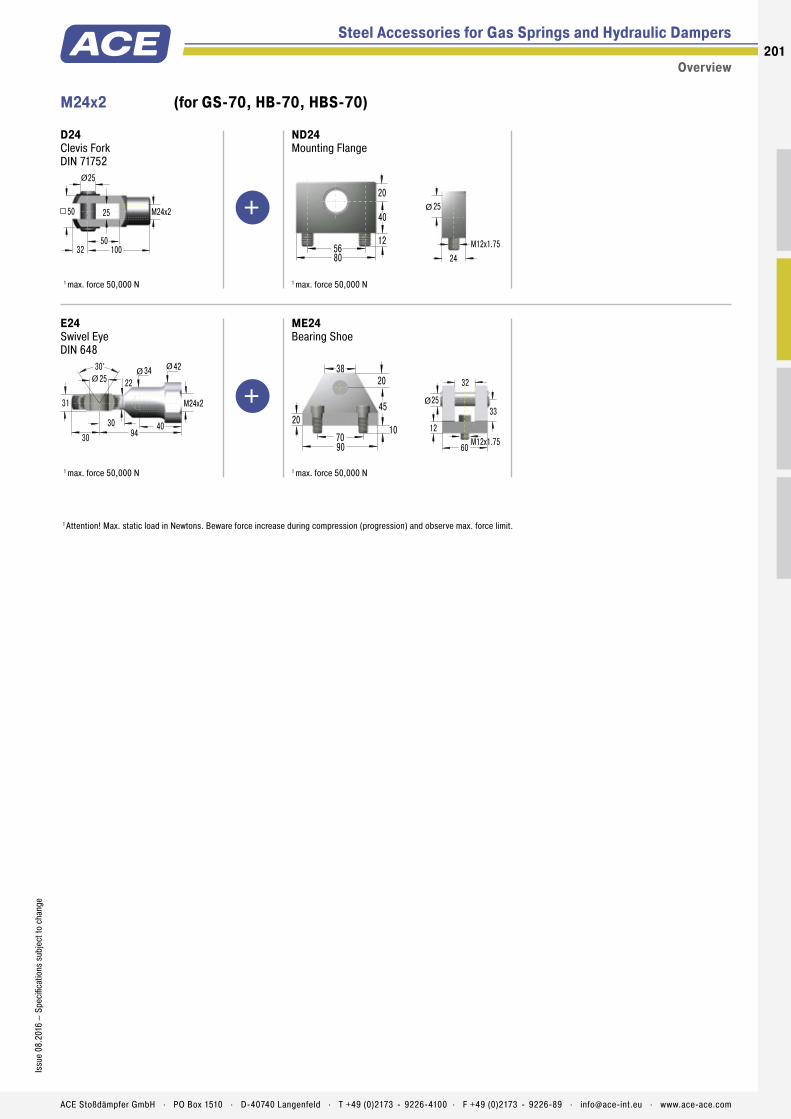
M24x2 (for GS-70, HB-70, HBS-70)
+
+
Overview
1 Attention! Max. static load in Newtons. Beware force increase during compression (progression) and observe max. force limit.
Steel Accessories for Gas Springs and Hydraulic Dampers
D24Clevis ForkDIN 71752
25
50
25
32 100
50
Ø
M24x2
1 max. force 50,000 N
ND24Mounting Flange
80
40
56
20
12
M12x1.75
24
25Ø
1 max. force 50,000 N
E24Swivel EyeDIN 648
30° 34 25
31
40
42
22
30 9430
ØØØ
M24x2
1 max. force 50,000 N
ME24Bearing Shoe
20
7090
45
2038
10
60
32
25
M12x1.75
33Ø
12
1 max. force 50,000 N
201Is
sue
08.2
016
– Sp
ecifi
catio
ns s
ubje
ct to
cha
nge
ACE Stoßdämpfer GmbH . PO Box 1510 . D-40740 Langenfeld . T +49 (0)2173 - 9226-4100 . F +49 (0)2173 - 9226-89 . [email protected] . www.ace-ace.com

Mounting Accessories for gas springs and hydraulic dampers made of stainless steel
Gas Springs and Hydraulic Dampers
For our gas springs and hydraulic dampers made of stainless steel we also offer a flexible product range of DIN standardised end fittings and mount-ing brackets. These eyes, swivel eyes, clevis forks, angle ball joints, ball sockets, inline ball joints and mounting brackets are also made of sturdy stainless steel and can be flexibly combined.
The high-quality stainless steel accessories are rustproof and weakly magnetic. Just as with the corresponding stainless steel gas springs and hydraulic dampers, they are preferred in the food, electronics and ship building industries along with medical and cleanroom technology.
All ACE stainless steel gas springs and the appropri-ate mounting accessories are individually designed for each application with the ACE calculation program.
The entire range of stainless steel accessories is also available separately.
202202
ACE Stoßdämpfer GmbH . PO Box 1510 . D-40740 Langenfeld . T +49 (0)2173 - 9226-4100 . [email protected] . www.ace-ace.com
Individual
Combinations!
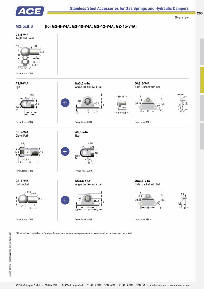
Stainless Steel Accessories for Gas Springs and Hydraulic Dampers
1 Attention! Max. static load in Newtons. Beware force increase during compression (progression) and observe max. force limit.
M3.5x0.6 (for GS-8-V4A, GS-10-V4A, GS-12-V4A, GZ-15-V4A)
+
+
+
Overview
C3,5-V4AAngle Ball Joint
18M4x0.7
8.5
13 8
6
10
36°
Ø Ø
M3.5
1 max. force 370 N
A3,5-V4AEye
8
11
4.14 thick
M3.5
6
8Ø
RadiusR4
1 max. force 370 N
NA3,5-V4AAngle Bracket with Ball
8
163191.5
3.4
4
10ØØ
4
3.5 4.5
5.75 4.25
Ø
1 max. force 180 N
OA3,5-V4ASide Bracket with Ball
185
5
15.68
13
5
4.3Ø
Ø
41
21.5
4.5 4.5
Ø
1 max. force 180 N
D3,5-V4AClevis Fork
4
8
4
5 16
8
Ø
M3.5
1 max. force 370 N
A3,5-V4AEye
8
11
4.14 thick
M3.5
6
8Ø
RadiusR4
1 max. force 370 N
G3,5-V4ABall Socket
18
4
13 8
68
ØØ
Ø
M3.5
1 max. force 370 N
NG3,5-V4AAngle Bracket with Ball
8
163191.5
3.4
4
10ØØ
1 max. force 180 N
OG3,5-V4ASide Bracket with Ball
185
5
15.68
13
5
4.3Ø
Ø
8
5.5
13.5
Ø
1 max. force 180 N
203Is
sue
08.2
016
– Sp
ecifi
catio
ns s
ubje
ct to
cha
nge
ACE Stoßdämpfer GmbH . PO Box 1510 . D-40740 Langenfeld . T +49 (0)2173 - 9226-4100 . F +49 (0)2173 - 9226-89 . [email protected] . www.ace-ace.com

Stainless Steel Accessories for Gas Springs and Hydraulic Dampers
Overview
M5x0.8 (for GS-15-VA)
+
+
1 Attention! Max. static load in Newtons. Beware force increase during compression (progression) and observe max. force limit.
C5-VAAngle Ball Joint
22M5
8
13 8
12
10
36°
Ø Ø
M5
1 max. force 430 N
D5-VAClevis Fork
5
10
5
6 20
10
Ø
M514
1 max. force 490 N
E5-VASwivel Eye
24° 10 5
8
12
13
4.5
10 2712
ØØØ
M5
1 max. force 490 N
MA5-V4ABearing Shoe
369.551
2.56.513
20
9Ø
6
6.5
18
2.54Ø
1 1 max. force 500 N
NA5-V4AAngle Bracket with Ball
345402
5.3
10
16Ø
6
6 7
10 10
Ø
1 max. force 400 N
A5-VAEye
9
16
6.16 thick
M5
8
10Ø
RadiusR5
1 max. force 490 N
OA5-V4ASide Bracket with Ball
185
5
15.613
5
4.3Ø
61
2.51.5
6.5 7
Ø
1 max. force 180 N
PA5-V4ARound Bracket with Ball
44
55415.3Ø
6
10
2.5
14 7
Ø
1 max. force 500 N
NG5-V4AAngle Bracket with Ball
345402
5.3
10
16Ø
8
13
5Ø
1 max. force 400 N
OG5-V4ASide Bracket with Ball
185
5
15.613
5
4.3Ø
8
5.5
13.5
Ø
1 max. force 180 N
G5-VABall Socket
22
4.5
13 8
128
ØØ
Ø
M5
1 max. force 430 N
PG5-V4ARound Bracket with Ball
44
55415.3Ø
8
218
2Ø
1 max. force 500 N
204
Issu
e 08
.201
6 –
Spec
ifica
tions
sub
ject
to c
hang
e
ACE Stoßdämpfer GmbH . PO Box 1510 . D-40740 Langenfeld . T +49 (0)2173 - 9226-4100 . F +49 (0)2173 - 9226-89 . [email protected] . www.ace-ace.com

Stainless Steel Accessories for Gas Springs and Hydraulic Dampers
Overview
1 Attention! Max. static load in Newtons. Beware force increase during compression (progression) and observe max. force limit.
M8x1.25 (for GS-19-VA, GS-22-VA, GZ-19-VA)
+
+
C8-VAAngle Ball Joint
30M8
12
20 13
15
16.5
36°
Ø Ø
M8
1 max. force 1,140 N
D8-VAClevis Fork
8
16
8
10 32
16
Ø
M822
1 max. force 1,560 N
A8-VAEye
11.5
19
8.110 thick
M8
10
14Ø
RadiusR7
1 max. force 1,560 N
MA8-V4ABearing Shoe
369.551
2.56.513
20
9Ø
18
8
13
4Ø
1 max. force 1,800 N
NA8-V4AAngle Bracket with Ball
345402
5.3
10
16Ø
8
7 11
10 10
Ø
1 max. force 1.000 N
OA8-V4ASide Bracket with Ball
557
10
3023
7
5.3Ø
82
3
10 11
Ø
1 max. force 1,200 N
PA8-V4ARound Bracket with Ball
44
55415.3Ø
8
10
15 11
Ø
1 max. force 1,200 N
E8-VASwivel Eye
24° 12 8
12
16
16
6
12 3613
ØØØ
M8
1 max. force 1,560 N
MA8-V4ABearing Shoe
369.551
2.56.513
20
9Ø
18
8
13
4Ø
1 max. force 1,800 N
205Is
sue
08.2
016
– Sp
ecifi
catio
ns s
ubje
ct to
cha
nge
ACE Stoßdämpfer GmbH . PO Box 1510 . D-40740 Langenfeld . T +49 (0)2173 - 9226-4100 . F +49 (0)2173 - 9226-89 . [email protected] . www.ace-ace.com

Stainless Steel Accessories for Gas Springs and Hydraulic Dampers
Overview
M8x1.25 (for GS-19-VA, GS-22-VA, GZ-19-VA)
+
M10x1.5 (for GS-28-VA, GZ-28-VA)
+
1 Attention! Max. static load in Newtons. Beware force increase during compression (progression) and observe max. force limit.
G8-VABall Socket
30
6
20 13
1513
ØØ
Ø
M8
1 max. force 1,140 N
NG8-V4AAngle Bracket with Ball
345402
5.3
10
16Ø
13
14.5
5Ø
1 max. force 1,000 N
OG8-V4ASide Bracket with Ball
557
10
3023
7
5.3Ø
13
8
17.5
Ø
1 max. force 1,200 N
PG8-V4ARound Bracket with Ball
44
55415.3Ø
13
22.5
9.5
Ø
1 max. force 1,200 N
C10-VAAngle Ball Joint
35M10
16
24 16
18
20
36°
Ø Ø
M10
1 max. force 1,750 N
D10-VAClevis Fork
10
20
10
12 40
20
Ø
M1026.5
1 max. force 3,800 N
E10-VASwivel Eye
24° 15 10
14
18
19
7
14 4316
ØØØ
M10
1 max. force 3,800 N
A10-VAEye
15
27
8.110 thick
M10
15
18Ø
RadiusR9
1 max. force 3,800 N
MA10-V4ABearing Shoe
369.551
2.56.513
20
9Ø
18
8
13
4Ø
1 max. force 1,800 N
206
Issu
e 08
.201
6 –
Spec
ifica
tions
sub
ject
to c
hang
e
ACE Stoßdämpfer GmbH . PO Box 1510 . D-40740 Langenfeld . T +49 (0)2173 - 9226-4100 . F +49 (0)2173 - 9226-89 . [email protected] . www.ace-ace.com
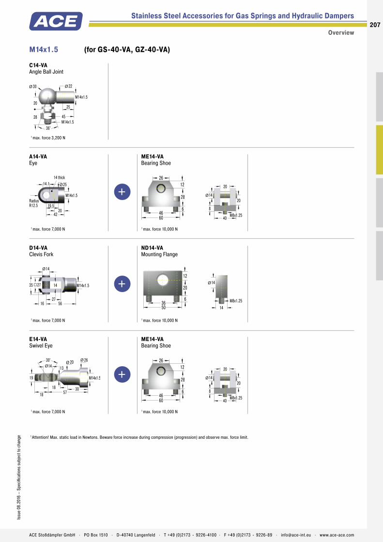
M14x1.5 (for GS-40-VA, GZ-40-VA)
+
+
+
1 Attention! Max. static load in Newtons. Beware force increase during compression (progression) and observe max. force limit.
Stainless Steel Accessories for Gas Springs and Hydraulic Dampers
Overview
C14-VAAngle Ball Joint
45M14x1.5
20
30 22
25
28
36°
Ø Ø
M14x1.5
1 max. force 3,200 N
A14-VAEye
19.5
42
14.114 thick
M14x1.5
20
25Ø
RadiusR12.5
1 max. force 7,000 N
ME14-VABearing Shoe
4660
28
1226
6
40
20
14
M8x1.25
20Ø
8
1 max. force 10,000 N
D14-VAClevis Fork
14
27
14
16 56
27
Ø
M14x1.535
1 max. force 7,000 N
ND14-VAMounting Flange
50
20
36
12
6
M8x1.25
14
14Ø
1 max. force 10,000 N
E14-VASwivel Eye
30° 20 14
19
30
26
13
18 5718
ØØØ
M14x1.5
1 max. force 7,000 N
ME14-VABearing Shoe
4660
28
1226
6
40
20
14
M8x1.25
20Ø
8
1 max. force 10,000 N
207Is
sue
08.2
016
– Sp
ecifi
catio
ns s
ubje
ct to
cha
nge
ACE Stoßdämpfer GmbH . PO Box 1510 . D-40740 Langenfeld . T +49 (0)2173 - 9226-4100 . F +49 (0)2173 - 9226-89 . [email protected] . www.ace-ace.com
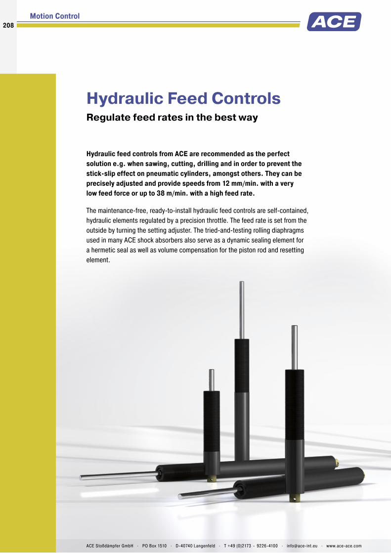
Hydraulic Feed ControlsRegulate feed rates in the best way
Hydraulic feed controls from ACE are recommended as the perfect solution e.g. when sawing, cutting, drilling and in order to prevent the stick-slip effect on pneumatic cylinders, amongst others. They can be precisely adjusted and provide speeds from 12 mm/min. with a very low feed force or up to 38 m/min. with a high feed rate.
The maintenance-free, ready-to-install hydraulic feed controls are self-contained, hydraulic elements regulated by a precision throttle. The feed rate is set from the outside by turning the setting adjuster. The tried-and-testing rolling diaphragms used in many ACE shock absorbers also serve as a dynamic sealing element for a hermetic seal as well as volume compensation for the piston rod and resetting element.
Motion Control208208
ACE Stoßdämpfer GmbH . PO Box 1510 . D-40740 Langenfeld . T +49 (0)2173 - 9226-4100 . [email protected] . www.ace-ace.com
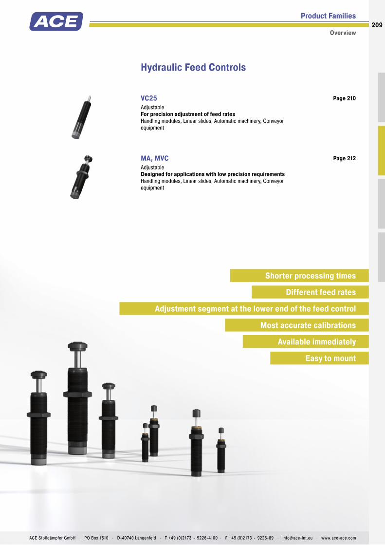
Product Families
Overview
Hydraulic Feed Controls
VC25 Adjustable For precision adjustment of feed ratesHandling modules, Linear slides, Automatic machinery, Conveyor equipment
Page 210
MA, MVC Adjustable Designed for applications with low precision requirementsHandling modules, Linear slides, Automatic machinery, Conveyor equipment
Page 212
Shorter processing times
Most accurate calibrations
Different feed rates
Adjustment segment at the lower end of the feed control
Easy to mount
Available immediately
209
ACE Stoßdämpfer GmbH . PO Box 1510 . D-40740 Langenfeld . T +49 (0)2173 - 9226-4100 . F +49 (0)2173 - 9226-89 . [email protected] . www.ace-ace.com

Piston Rod
Main Bearing
Positive Stop
Outer Body
Piston
Fine Filter
Pressure Chamber
Adjustment Segment with Precision Tapered V-Groove
Technical Data
Precise adjustment for any type of application: The VC model of hydraulic feed controls is ideally suited for the precise tuning of constant feed rates. The thread of the outer body of this closed hydraulic element allows simple assembly. Designs with a smooth body can also be supplied.
As the hydraulic oil is forced out through the throttle opening, a constant feed rate is achieved on the stroke, which also avoids the stick-slip effect. In the models up to 55 mm stroke, the tried and tested rolling diaphragm, known from ACE shock absorbers, serves as a dynamic seal, as volume compensation of the piston rod and as a reset element.
The VC model of precision hydraulic feed controls is used in automotive and industrial applications as well as in automation and machine building and electronics industries.
VC25Hydraulic Feed Controls For precision adjustment of feed rates
Hydraulic Feed Controls
Adjustable
Compression force: 30 N to 3,500 NExecution: F = Ø 23.8 mm without threadFT = M25x1.5 threaded bodyPiston rod diameter: Ø 8 mmFeed rate/Compression force: Min. 0.013 m/min. at 400 N; Max. 38 m/min. at 3,500 NImpact velocity range: At speeds of 0.3 m/s the maximum allowed energy is approx. 1 Nm for units up to 55 mm stroke and approx. 2 Nm for units 75 mm to 125 mm stroke. Where higher energies occur use a shock absorber for the initial impact. Avoid high impact velocities.Adjustment: Infi nitely adjustable
Positive stop: External positive stops 1 mm to 1.5 mm before the end of stroke provided by the customer.Damping medium: Oil, temperature stableMaterial: Outer body: Black anodized aluminium; Piston rod: Hard chrome plated steel; Accessories: Steel with black oxide fi nish or nitride hardenedMounting: In any positionOperating temperature range: 0 °C to 60 °CApplication fi eld: Handling modules, Linear slides, Automatic machinery, Conveyor equipment
Note: Nylon button PP600 can be fi tted onto piston rod. Unit may be mounted in any position.Safety instructions: Do not rotate piston rod, if excessive rotation force is applied rolling seal may rupture. External materials in the surround-ing area can attack the seal components and lead to a shorter service life. Please contact ACE for appropriate solution suggestions.On request: Special oil and other special options available on request.
210
Issu
e 08
.201
6 –
Spec
ifi ca
tions
sub
ject
to c
hang
e
ACE Stoßdämpfer GmbH . PO Box 1510 . D-40740 Langenfeld . T +49 (0)2173 - 9226-4100 . F +49 (0)2173 - 9226-89 . [email protected] . www.ace-ace.com

Piston Rod
Main Bearing
Positive Stop
Outer Body
Piston
Fine Filter
Pressure Chamber
Adjustment Segment with Precision Tapered V-Groove
Hydraulic Feed Controls VC25EUFT
Adjustable
25
AB
Stroke16
Stop
8KM25M25x1.5
Ø
Ø
VC25EUFT
Additional accessories, mounting, installation ... see from page 42.
Ordering Example VC 25 55 EUFTType (Feed Control)Thread Size M25Stroke (55 mm)EU CompliantFT = mit Gewinde M25x1,5F = without thread, plain body (Ø 23.8 mm)
Complete details required when ordering Load to be decelerated: m (kg)Impact velocity: v (m/s)Propelling force: F (N)Operating cycles per hour: c (/hr)Number of absorbers in parallel: nAmbient temperature: °C
Performance and Dimensions
TYPESStroke
mmA
mmB
mm
Compression Force min.
N
Compression Force max.
NReturn force min.
NReturn force max.
NReturn time
s
Side Load Angle max.
°Weight
kgVC2515EUFT 15 128 80 30 3,500 15 30 0.2 3 0.350VC2530EUFT 30 161 110 30 3,500 5 30 0.4 2 0.450VC2555EUFT 55 209 130 35 3,500 5 40 1.2 2 0.423VC2575EUFT 75 283 150 50 3,500 10 50 1,7 2 0.681VC25100EUFT 100 308 150 60 3,500 10 50 2.3 1 0.794VC25125EUFT 125 333.5 150 70 3,500 10 60 2.8 1 0.908Suffi x FT: M25x1.5 threaded body. Suffi x F: plain body 23.8 mm dia. (without thread), with optional clamp type mounting block.
25.4 19.1
Bulkhead mounting for VC25...F with mountingblock KB... (23.8 mm plain body option)
Alternative circlip grooves
Installed with switch stop collar inc. proximity switch and steel button AS25 plus PS25
Installed with air bleed collar SP25
Mounting with clamp mount MB25
x 1 x 10 x 100 x 1000
Speed (mm/min)
Prop
ellin
g Fo
rce
(N)
3500
3000
2500
2000
1500
1000
500
0 6 12 24 36 6 12 24 36 6 12 24 36 6 12 24 36
VC2515 – VC25125
Operating Range VC Accessories with Mounting Example
MB25 Clamp Mount
46
32
6
M25x1.5
M634
25
SP25 Air Bleed Collar
30
6.416
M25x1.5AF23
3
Ø
Ø
For VC2515FT to VC2555FT reduction of the stroke 6.4 mm
211Is
sue
08.2
016
– Sp
ecifi
catio
ns s
ubje
ct to
cha
nge
ACE Stoßdämpfer GmbH . PO Box 1510 . D-40740 Langenfeld . T +49 (0)2173 - 9226-4100 . F +49 (0)2173 - 9226-89 . [email protected] . www.ace-ace.com
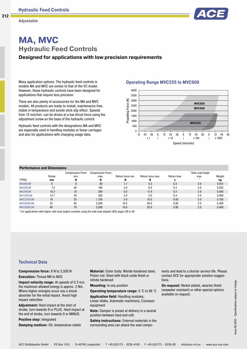
Technical Data
Many application options: The hydraulic feed controls in models MA and MVC are similar to that of the VC model. However, these hydraulic controls have been designed for applications that require less precision.
There are also plenty of accessories for the MA and MVC models. All products are ready-to-install, maintenance-free, stable in temperature and avoids stick-slip effect. Speeds from 12 mm/min. can be driven at a low thrust force using the adjustment screw on the base of the hydraulic control.
Hydraulic feed controls with the designations MA and MVC are especially used in handling modules or linear carriages and also for applications with changing usage data.
MA, MVCHydraulic Feed Controls Designed for applications with low precision requirements
Hydraulic Feed Controls
Adjustable
Compression force: 8 N to 3,500 NExecution: Thread M8 to M25Impact velocity range: At speeds of 0.3 m/s the maximum allowed energy is approx. 2 Nm. Where higher energies occur use a shock absorber for the initial impact. Avoid high impact velocities.Adjustment: Hard impact at the start of stroke, turn towards 9 or PLUS. Hard impact at the end of stroke, turn towards 0 or MINUS.Positive stop: IntegratedDamping medium: Oil, temperature stable
Material: Outer body: Nitride hardened steel; Piston rod: Steel with black oxide finish or nitride hardenedMounting: In any positionOperating temperature range: 0 °C to 66 °CApplication field: Handling modules, Linear slides, Automatic machinery, Conveyor equipmentNote: Damper is preset at delivery in a neutral position between hard and soft.Safety instructions: External materials in the surrounding area can attack the seal compo-
nents and lead to a shorter service life. Please contact ACE for appropriate solution sugges-tions.On request: Nickel-plated, weartec finish (seawater resistant) or other special options available on request.
Operating Range MVC225 to MVC900
x 1 x 10 x 100 x 1000
Speed (mm/min)
Prop
ellin
g Fo
rce
(N)
4000
3500
3000
2500
2000
1500
1000
500
0 12 24 36 6 12 24 36 6 12 24 36 6 12 24 36
MVC600
MVC225
MVC900
Performance and Dimensions
TYPESStroke
mm
Compression Force min.
N
Compression Force max.
NReturn force min.
NReturn force max.
NReturn time
s
1 Side Load Angle max.
°Weight
kgMA30EUM 8 8 80 1.7 5.3 0.3 2.0 0.013MA50EUM 7.2 40 160 3.0 6.0 0.3 2.0 0.025MA35EUM 10.2 15 200 5.0 11.0 0.2 2.0 0.043MA150EUM 12.7 20 300 3.0 5.0 0.4 2.0 0.060MVC225EUM 19 25 1,750 5.0 10.0 0.65 2.0 0.150MVC600EUM 25 65 3,500 10.0 30.0 0.85 2.0 0.300MVC900EUM 40 70 3,500 10.0 35.0 0.95 2.0 0.400
1 For applications with higher side load angles consider using the side load adaptor (BV) pages 38 to 45.
212
Issu
e 08
.201
6 –
Spec
ifica
tions
sub
ject
to c
hang
e
ACE Stoßdämpfer GmbH . PO Box 1510 . D-40740 Langenfeld . T +49 (0)2173 - 9226-4100 . F +49 (0)2173 - 9226-89 . [email protected] . www.ace-ace.com

Hydraulic Feed Controls MA, MVC
Adjustable
3 StrokeAF10848.3 13.1
2.56.4M8x14.1
Adjustment Screw
2.1
2.5 ØØ
MA30EUM
MB8SC2 Mounting Block
25
12
3.5
M8x1
M4
16
10
RF8 Rectangular Flange
25
14
6M8x1
18
M4x10
4 StrokeAF127.249.8 14.9
3.27.7M10x15.1
Adjustment Screw
3
2.5 ØØ
MA50EUM
MB10SC2 Mounting Block
25
14
3.5
M10x1
M4
16
10
RF10 Rectangular Flange
28
14
6M10x1
20
M4x10
5 StrokeAF1410.265.7 18.2
3.27.7M12x15
Adjustment Screw
3
2.5 ØØ
MA35EUM
MB12 Clamp Mount
32
16
4.5
M12x1
M5
20
12
RF12 Rectangular Flange
32
20
6M12x1
24
M5x12
4.84.7
12M14x1.57.1 AF12 6
69.1
AF17 12.722.5
Stroke
Adjustment Screw
Ø
Ø
MA150EUM
MB14 Clamp Mount
32
20
4.5
M14x1.5
M520
12
RF14 Rectangular Flange
34
20
6M14x1.5
26
M5x12
4.84.6
17M20x1.513.5 8
8819
30
StrokeAF23
4.8AF18
Ø
Ø
Adjustment KnobMVC225EUM
MB20 Clamp Mount
40
25
6
M20x1.5
M628
20
RF20 Rectangular Flange
46
32
8M20x1.5
36
M6x14
6.34.6
23M25x1.516.5 10
106.625.4
36.4
StrokeAF30
5AF23
Ø
Ø
Adjustment KnobMVC600EUM
MB25 Clamp Mount
46
32
6
M25x1.5
M634
25
RF25 Rectangular Flange
52
32
8M25x1.5
42
M6x14
6.34.6
23M25x1.516.5 10
13840
51
StrokeAF30
5AF23
Ø
Ø
Adjustment KnobMVC900EUM
MB25 Clamp Mount
46
32
6
M25x1.5
M634
25
RF25 Rectangular Flange
52
32
8M25x1.5
42
M6x14
Additional accessories, mounting, installation ... see from page 38.
213Is
sue
08.2
016
– Sp
ecifi
catio
ns s
ubje
ct to
cha
nge
ACE Stoßdämpfer GmbH . PO Box 1510 . D-40740 Langenfeld . T +49 (0)2173 - 9226-4100 . F +49 (0)2173 - 9226-89 . [email protected] . www.ace-ace.com

214214
ACE Stoßdämpfer GmbH . PO Box 1510 . D-40740 Langenfeld . T +49 (0)2173 - 9226-4100 . [email protected] . www.ace-ace.comACE Stoßdämpfer GmbH . PO Box 1510 . D-40740 Langenfeld . T +49 (0)2173 - 9226-4100 . [email protected] . www.ace-ace.com
Damping Vane
Fluid
Sealing Ring
ACE rotary dampers mainly provide an invisible yet valuable service as a maintenance-free machine element to allow controlled deceleration of rotary or linear movements.
They are often necessary to make careful opening and closing of small lids, compartments and drawers possible and they protect sensitive components while increasing the quality and value of products. They are easy to integrate. The harmoniously gentle movements of these little decelerators can be achieved with continual rotation or with limited pivoting angles. They slow down left, right or double sided rotation. Suitable for almost any application and currently also availa-ble in adjustable variations, they provide braking torques of 0.05 Ncm to 40 Nm.
Rotary DampersSmall dampers refi ne end product
Motion Control
General Function
Rotary dampers operate on the principle of fl uid damping. The damping moment is determined by the viscosity of the fl uid and the dimensioning of the throttle gap or throttle orifi ces.
Partial Rotation Angle, Adjustable e.g. FYT-H1 and FYN-H1

ACE Stoßdämpfer GmbH . PO Box 1510 . D-40740 Langenfeld . T +49 (0)2173 - 9226-4100 . F +49 (0)2173 - 9226-89 . [email protected] . www.ace-ace.com
215
ACE Stoßdämpfer GmbH . PO Box 1510 . D-40740 Langenfeld . T +49 (0)2173 - 9226-4100 . F +49 (0)2173 - 9226-89 . [email protected] . www.ace-ace.com
End Cap
Sealing Ring
Sealing Ring
Rotor
Cover
Rotor
Roatary Dampers
Technical Information
Rotary Dampers with Continuous Rotation
Rotate for the plus in quality: For smooth, quiet movements of small hoods, fl aps and fans these continuously rotating rotary dampers from ACE decelerate either right, left or two-sided rotation right in the pivot point or linear through a gear and gear rack. The harmoniously gentle process protects components and increases the quality and value of products. The maintenance-free, ready-to-install ACE rotary dampers are fi lled with an inert fl uid, usually silicone oil. The viscosity of the fl uid and the sizing of the throttling gap determine the damping torque. The FFD series is the only exception: These fl uid-free rotary dampers operate according to the principle of friction.
The continuously rotating rotary dampers with the designations FRT, FRN, FFD, FDT and FDN are used in household and medical devices as well as in the automotive, electronics and furniture industries.
Rotary Dampers with Partial Rotation Angle
For controlled and gentle deceleration: The damping direction of this rotary damper, which is available with adjustable damping torque, can be right, left or two-sided rotation. They can be installed directly in the pivot point of a construction and achieve uniform, quiet movements, which increases quality and value and protects sensitive components. The products are maintenance-free, ready-to-install and fi lled with an inert fl uid, usually silicone oil. A rotor movement presses the fl uid from one chamber into the other. The damping torque is determined by the viscosity of the fl uid and the sizing of the throttling gap the throttle holes. During each reversal of movement, depending on the frame size a certain return damping torque develops.
These solutions are used in the automotive sector, in many industrial applications, in the electronics and furniture industries as well as in medical devices.
Partial Rotation Anglee.g. FYN-N1
Continuous Rotation e.g. FRT-E2
High protection of sensitive components
Various designs for every application
Maintenance-free and ready-to-install

Product Families
Overview
Rotary Dampers
FRT-E2 Continuous Rotation Small and lightweight for fi nest braking
Page 218
FRT-G2 Continuous Rotation Small and lightweight for fi nest braking
Page 219
FRT-C2 and FRN-C2 Continuous Rotation Flexible and cost effi cient use
Page 220
FRT-D2 and FRN-D2 Continuous Rotation Flexible and cost effi cient use
Page 221
FRT-F2/K2 and FRN-F2/K2 Continuous Rotation For very long service life extension
Page 222
FFD Continuous Rotation Precise braking without oil
Page 223
FDT Continuous Rotation The fl at disc brake for two-sided damping
Page 224
FDN Continuous Rotation The fl at disc brake for one direction of rotation
Page 225
Continuous rotation
216
Issu
e 08
.201
6 –
Spec
ifi ca
tions
sub
ject
to c
hang
e
ACE Stoßdämpfer GmbH . PO Box 1510 . D-40740 Langenfeld . T +49 (0)2173 - 9226-4100 . F +49 (0)2173 - 9226-89 . [email protected] . www.ace-ace.com

Product Families
Overview
Rotary Dampers
FYN-P1 Partial Rotation Angle Small diameter, large damping torques
Page 226
FYN-N1 Partial Rotation Angle Small diameter, large braking torques
Page 227
FYN-U1 Partial Rotation Angle Small, strong and very robust
Page 228
FYN-S1 Partial Rotation Angle The fl at damper for constant component protection
Page 229
FYT-H1 and FYN-H1 Partial Rotation Angle, Adjustable Specifi c adjustable, strong braking force
Page 230
FYT-LA3 and FYN-LA3 Partial Rotation Angle, Adjustable Adjustable High Performance
Page 231
Partial rotation angle
Partial rotation angle, adjustable
217Is
sue
08.2
016
– Sp
ecifi
catio
ns s
ubje
ct to
cha
nge
ACE Stoßdämpfer GmbH . PO Box 1510 . D-40740 Langenfeld . T +49 (0)2173 - 9226-4100 . F +49 (0)2173 - 9226-89 . [email protected] . www.ace-ace.com
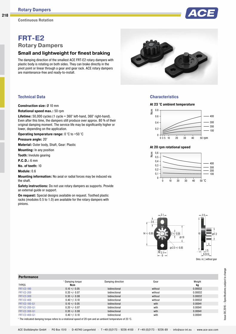
The damping direction of the smallest ACE FRT-E2 rotary dampers with plastic body is rotating on both sides. They can brake directly in the pivot point or linear through a gear and gear rack. ACE rotary dampers are maintenance-free and ready-to-install.
FRT-E2Rotary Dampers Small and lightweight for finest braking
Rotary Dampers
Continuous Rotation
Technical Data
Construction size: Ø 10 mmRotational speed max.: 50 rpmLifetime: 50,000 cycles (1 cycle = 360° left-hand, 360° right-hand). Even after this time, the dampers still produce over approx. 80 % of their original damping moment. The service life may be significantly higher or lower, depending on the application.Operating temperature range: 0 °C to +50 °CPressure angle: 20°Material: Outer body, Shaft, Gear: PlasticMounting: In any positionTooth: Involute gearingP.C.D.: 6 mmNo. of teeth: 10Module: 0.6Mounting information: No axial or radial forces may be induced via the shaft.Safety instructions: Do not use rotary dampers as supports. Provide an external guide or support.On request: Special designs available on request. Toothed plastic racks (modules 0.5 to 1.0) are available for the rotary dampers with pinions.
0.8
0.6
0.4
0.2
0
400
300200100
Ncm
0 3 5 10 20 30 40 50 rpm
0,60,50,40,30,20,1
0
400300200100
Ncm
0 10 20 30 40 50 °C
CharacteristicsAt 23 °C ambient temperature
At 20 rpm rotational speed
Performance
TYPES
1 Damping torqueNcm
Damping direction Gear Weightkg
FRT-E2-100 0.10 +/- 0.05 bidirectional without 0.00032FRT-E2-200 0.20 +/- 0.07 bidirectional without 0.00032FRT-E2-300 0.30 +/- 0.08 bidirectional without 0.00032FRT-E2-400 0.40 +/- 0.10 bidirectional without 0.00032FRT-E2-100-G1 0.10 +/- 0.05 bidirectional with 0.00041FRT-E2-200-G1 0.20 +/- 0.07 bidirectional with 0.00041FRT-E2-300-G1 0.30 +/- 0.08 bidirectional with 0.00041FRT-E2-400-G1 0.40 +/- 0.10 bidirectional with 0.00041
1 The indicated damping torque refers to a rotational speed of 20 rpm and an ambient temperature of 23 °C.
14 +/- 0.05 2 +/- 0.05
2.1
2.6
2.5 +/- 0.05
10
2.16
Ø
ØØ
19
1.5
3
2.5
6 (5.5)
7.2Ø
Dims. in ( ) without gear
218
Issu
e 08
.201
6 –
Spec
ifica
tions
sub
ject
to c
hang
e
ACE Stoßdämpfer GmbH . PO Box 1510 . D-40740 Langenfeld . T +49 (0)2173 - 9226-4100 . F +49 (0)2173 - 9226-89 . [email protected] . www.ace-ace.com
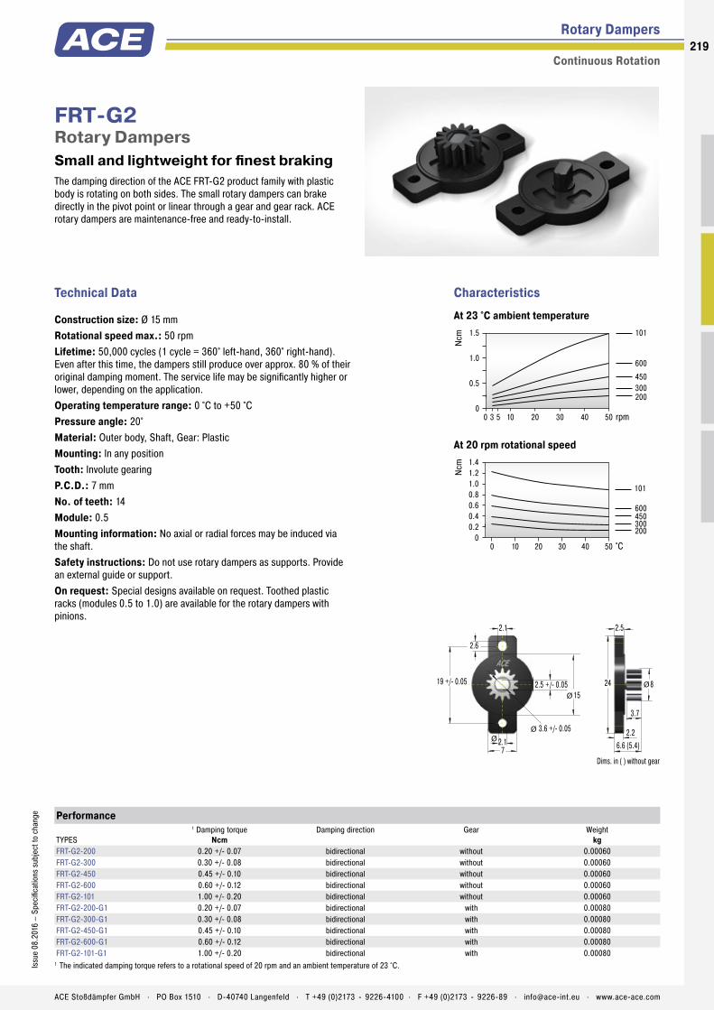
The damping direction of the ACE FRT-G2 product family with plastic body is rotating on both sides. The small rotary dampers can brake directly in the pivot point or linear through a gear and gear rack. ACE rotary dampers are maintenance-free and ready-to-install.
FRT-G2Rotary Dampers Small and lightweight for finest braking
Rotary Dampers
Continuous Rotation
Technical Data
Construction size: Ø 15 mmRotational speed max.: 50 rpmLifetime: 50,000 cycles (1 cycle = 360° left-hand, 360° right-hand). Even after this time, the dampers still produce over approx. 80 % of their original damping moment. The service life may be significantly higher or lower, depending on the application.Operating temperature range: 0 °C to +50 °CPressure angle: 20°Material: Outer body, Shaft, Gear: PlasticMounting: In any positionTooth: Involute gearingP.C.D.: 7 mmNo. of teeth: 14Module: 0.5Mounting information: No axial or radial forces may be induced via the shaft.Safety instructions: Do not use rotary dampers as supports. Provide an external guide or support.On request: Special designs available on request. Toothed plastic racks (modules 0.5 to 1.0) are available for the rotary dampers with pinions.
1.5
1.0
0.5
0
101
600
450300200
Ncm
0 3 5 10 20 30 40 50 rpm
1.41.21.00.80.60.40.2
0 0 10 20 30 40 50
101
600450300200
Ncm
°C
CharacteristicsAt 23 °C ambient temperature
At 20 rpm rotational speed
Performance
TYPES
1 Damping torqueNcm
Damping direction Gear Weightkg
FRT-G2-200 0.20 +/- 0.07 bidirectional without 0.00060FRT-G2-300 0.30 +/- 0.08 bidirectional without 0.00060FRT-G2-450 0.45 +/- 0.10 bidirectional without 0.00060FRT-G2-600 0.60 +/- 0.12 bidirectional without 0.00060FRT-G2-101 1.00 +/- 0.20 bidirectional without 0.00060FRT-G2-200-G1 0.20 +/- 0.07 bidirectional with 0.00080FRT-G2-300-G1 0.30 +/- 0.08 bidirectional with 0.00080FRT-G2-450-G1 0.45 +/- 0.10 bidirectional with 0.00080FRT-G2-600-G1 0.60 +/- 0.12 bidirectional with 0.00080FRT-G2-101-G1 1.00 +/- 0.20 bidirectional with 0.00080
1 The indicated damping torque refers to a rotational speed of 20 rpm and an ambient temperature of 23 °C.
2.6
19 +/- 0.05
2.1
2.1
7
2.5 +/- 0.0515
3.6 +/- 0.05ØØ
Ø824
2.2
3.7
2.5
6.6 (5.4)
Ø
Dims. in ( ) without gear
219Is
sue
08.2
016
– Sp
ecifi
catio
ns s
ubje
ct to
cha
nge
ACE Stoßdämpfer GmbH . PO Box 1510 . D-40740 Langenfeld . T +49 (0)2173 - 9226-4100 . F +49 (0)2173 - 9226-89 . [email protected] . www.ace-ace.com
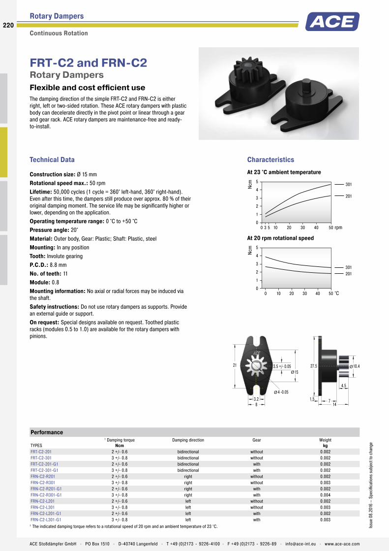
The damping direction of the simple FRT-C2 and FRN-C2 is either right, left or two-sided rotation. These ACE rotary dampers with plastic body can decelerate directly in the pivot point or linear through a gear and gear rack. ACE rotary dampers are maintenance-free and ready- to-install.
FRT-C2 and FRN-C2Rotary Dampers Flexible and cost efficient use
Rotary Dampers
Continuous Rotation
Technical Data
Construction size: Ø 15 mmRotational speed max.: 50 rpmLifetime: 50,000 cycles (1 cycle = 360° left-hand, 360° right-hand). Even after this time, the dampers still produce over approx. 80 % of their original damping moment. The service life may be significantly higher or lower, depending on the application.Operating temperature range: 0 °C to +50 °CPressure angle: 20°Material: Outer body, Gear: Plastic; Shaft: Plastic, steelMounting: In any positionTooth: Involute gearingP.C.D.: 8.8 mmNo. of teeth: 11Module: 0.8Mounting information: No axial or radial forces may be induced via the shaft.Safety instructions: Do not use rotary dampers as supports. Provide an external guide or support.On request: Special designs available on request. Toothed plastic racks (modules 0.5 to 1.0) are available for the rotary dampers with pinions.
0 3 5 10 20 30 40 50
301
201
Ncm
rpm
5
4
3
2
1
0
5
4
3
2
1
0
301201
Ncm
0 10 20 30 40 50 °C
CharacteristicsAt 23 °C ambient temperature
At 20 rpm rotational speed
Performance
TYPES
1 Damping torqueNcm
Damping direction Gear Weightkg
FRT-C2-201 2 +/- 0.6 bidirectional without 0.002FRT-C2-301 3 +/- 0.8 bidirectional without 0.002FRT-C2-201-G1 2 +/- 0.6 bidirectional with 0.002FRT-C2-301-G1 3 +/- 0.8 bidirectional with 0.002FRN-C2-R201 2 +/- 0.6 right without 0.002FRN-C2-R301 3 +/- 0.8 right without 0.003FRN-C2-R201-G1 2 +/- 0.6 right with 0.002FRN-C2-R301-G1 3 +/- 0.8 right with 0.004FRN-C2-L201 2 +/- 0.6 left without 0.002FRN-C2-L301 3 +/- 0.8 left without 0.003FRN-C2-L201-G1 2 +/- 0.6 left with 0.002FRN-C2-L301-G1 3 +/- 0.8 left with 0.003
1 The indicated damping torque refers to a rotational speed of 20 rpm and an ambient temperature of 23 °C.
1521 3.5 +/- 0.05
3.28
4 -0.05
Ø
Ø
10.427.5
1.5
4.5
714
Ø
220
Issu
e 08
.201
6 –
Spec
ifica
tions
sub
ject
to c
hang
e
ACE Stoßdämpfer GmbH . PO Box 1510 . D-40740 Langenfeld . T +49 (0)2173 - 9226-4100 . F +49 (0)2173 - 9226-89 . [email protected] . www.ace-ace.com

The damping direction of the ACE FRT-D2 and FRN-D2 rotary dampers with plastic body is either the right, left or two-sided rotation. They can decelerate directly in the pivot point or linear through a gear and gear rack. ACE rotary dampers are maintenance-free and ready-to-install.
FRT-D2 and FRN-D2Rotary Dampers Flexible and cost efficient use
Rotary Dampers
Continuous Rotation
Technical Data
Construction size: Ø 25 mmRotational speed max.: 50 rpmLifetime: 50,000 cycles (1 cycle = 360° left-hand, 360° right-hand). Even after this time, the dampers still produce over approx. 80 % of their original damping moment. The service life may be significantly higher or lower, depending on the application.Operating temperature range: 0 °C to +50 °CPressure angle: 20°Material: Outer body, Gear: Plastic; Shaft: Plastic, steelMounting: In any positionTooth: Involute gearing (addendum modification coefficient: +0.375)P.C.D.: 12 mmNo. of teeth: 12Module: 1Mounting information: No axial or radial forces may be induced via the shaft.Safety instructions: Do not use rotary dampers as supports. Provide an external guide or support.On request: Special designs available on request. Toothed plastic racks (modules 0.5 to 1.0) are available for the rotary dampers with pinions.
20
15
10
5
0
152
102
501
Ncm
0 3 5 10 20 30 40 50 rpm
20
15
10
5
0
152
102501
Ncm
0 10 20 30 40 50 °C
CharacteristicsAt 23 °C ambient temperature
At 20 rpm rotational speed
Performance
TYPES
1 Damping torqueNcm
Damping direction Gear Weightkg
FRT-D2-102 10 +/- 2 bidirectional without 0.008FRT-D2-152 15 +/- 3 bidirectional without 0.008FRT-D2-501 5 +/- 1 bidirectional without 0.008FRT-D2-102-G1 10 +/- 2 bidirectional with 0.009FRT-D2-152-G1 15 +/- 3 bidirectional with 0.009FRT-D2-501-G1 5 +/- 1 bidirectional with 0.009FRN-D2-R102 10 +/- 2 right without 0.012FRN-D2-R152 15 +/- 3 right without 0.012FRN-D2-R501 5 +/- 1 right without 0.012FRN-D2-R102-G1 10 +/- 2 right with 0.012FRN-D2-R152-G1 15 +/- 3 right with 0.012FRN-D2-R501-G1 5 +/- 1 right with 0.012FRN-D2-L102 10 +/- 2 left without 0.012FRN-D2-L152 15 +/- 3 left without 0.012FRN-D2-L501 5 +/- 1 left without 0.012FRN-D2-L102-G1 10 +/- 2 left with 0.012FRN-D2-L152-G1 15 +/- 3 left with 0.012FRN-D2-L501-G1 5 +/- 1 left with 0.012
1 The indicated damping torque refers to a rotational speed of 20 rpm and an ambient temperature of 23 °C.
2540 4 +/- 0.05
5 -0.05
4.2 R5
Ø
Ø
Ø
14.7550
2
5
1119
Ø
221Is
sue
08.2
016
– Sp
ecifi
catio
ns s
ubje
ct to
cha
nge
ACE Stoßdämpfer GmbH . PO Box 1510 . D-40740 Langenfeld . T +49 (0)2173 - 9226-4100 . F +49 (0)2173 - 9226-89 . [email protected] . www.ace-ace.com

The damping direction of FRT F2/K2 and FRN-F2/K2 is either the right, left or two-sided rotation. With a damping torque of up to 400 Ncm, this product family can even handle heavy components. These ACE rotary dampers can decelerate directly in the pivot point or linear through a gear and gear rack. They are maintenance-free and ready-to-install.
FRT-F2/K2 and FRN-F2/K2Rotary Dampers For very long service life extension
Rotary Dampers
Continuous Rotation
Technical Data
Construction size: Ø 40 mmRotational speed max.: 50 rpmLifetime: 50,000 cycles (1 cycle = 360° left-hand, 360° right-hand). Even after this time, the dampers still produce over approx. 80 % of their original damping moment. The service life may be significantly higher or lower, depending on the application.Operating temperature range: 0 °C to +50 °CMaterial: Outer body: Plastic; Shaft: SteelMounting: In any positionMounting information: No axial or radial forces may be induced via the shaft.Safety instructions: Do not use rotary dampers as supports. Provide an external guide or support.On request: Special designs available on request.
600500400300200100
00 10 20 30 40 50
403303
203103
502
Ncm
rpm
600500400300200100
00 10 20 30 40 50
403303203103502
Ncm
°C
CharacteristicsAt 23 °C ambient temperature
At 20 rpm rotational speed
Performance
TYPES
1 Damping torqueNcm
Damping direction Weightkg
FRT-K2-502 50 +/- 10 bidirectional 0.080FRT-K2-103 100 +/- 20 bidirectional 0.080FRT-F2-203 200 +/- 40 bidirectional 0.110FRT-F2-303 300 +/- 80 bidirectional 0.115FRT-F2-403 400 +/- 100 bidirectional 0.115FRN-K2-R502 50 +/- 10 right 0.057FRN-K2-R103 100 +/- 20 right 0.057FRN-F2-R203 200 +/- 40 right 0.090FRN-K2-L502 50 +/- 10 left 0.057FRN-K2-L103 100 +/- 20 left 0.057FRN-F2-L203 200 +/- 40 left 0.090
1 The indicated damping torque refers to a rotational speed of 20 rpm and an ambient temperature of 23 °C.
0-0.1
5.2 6 R5.5
4736
ØØ
5 +/- 0.05
51629.5
42
10
1.5
13.5Ø 40 Ø
222
Issu
e 08
.201
6 –
Spec
ifica
tions
sub
ject
to c
hang
e
ACE Stoßdämpfer GmbH . PO Box 1510 . D-40740 Langenfeld . T +49 (0)2173 - 9226-4100 . F +49 (0)2173 - 9226-89 . [email protected] . www.ace-ace.com
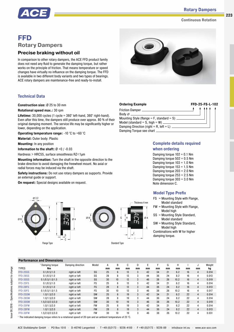
In comparison to other rotary dampers, the ACE FFD product family does not need any fluid to generate the damping torque, but rather works on the principle of friction. That means temperature or speed changes have virtually no influence on the damping torque. The FFD is available in two different body variants and two types of bearings. ACE rotary dampers are maintenance-free and ready-to-install.
FFDRotary Dampers Precise braking without oil
Rotary Dampers
Continuous Rotation
Technical Data
Construction size: Ø 25 to 30 mmRotational speed max.: 30 rpmLifetime: 30,000 cycles (1 cycle = 360° left-hand, 360° right-hand). Even after this time, the dampers still produce over approx. 80 % of their original damping moment. The service life may be significantly higher or lower, depending on the application.Operating temperature range: -10 °C to +60 °CMaterial: Outer body: PlasticMounting: In any positionInformation to the shaft: Ø +0 / -0.03Hardness > HRC55, surface smoothness RZ<1µmMounting information: Turn the shaft in the opposite direction to the brake direction to avoid damaging the freewheel mount. No axial or radial forces may be induced via the shaft.Safety instructions: Do not use rotary dampers as supports. Provide an external guide or support.On request: Special designs available on request.
Ordering Example FFD-25-FS-L-102Friction DamperBody �Mounting Style (flange = F, standard = S)Model (standard = S, high = W)Damping Direction (right = R, left = L)Damping Torque see chart
Complete details required when ordering Damping torque 102 = 0.1 NmDamping torque 502 = 0.5 NmDamping torque 103 = 1.0 NmDamping torque 153 = 1.5 NmDamping torque 203 = 2.0 NmDamping torque 253 = 2.5 NmDamping torque 303 = 3.0 NmNote dimension C.
Model Type PrefixFS = Mounting Style with Flange,
Model standardFW = Mounting Style with Flange,
Model highSS = Mounting Style Standard,
Model standardSW = Mounting Style Standard,
Model highCombinations with W for higher damping torque.
Performance and Dimensions
TYPES
1 Damping torqueNm
Damping direction Model Amm
Bmm
Cmm
Dmm
Emm
Fmm
Gmm
Hmm
Imm
Jmm
Weightkg
FFD-25SS 0.1/0.5/1.0 right or left SS 25 6 13 3 42 34 21 6.2 16 4 0.014FFD-28SS 0.1/0.5/1.0 right or left SS 28 8 13 3 44 36 24 8.2 16 4 0.013FFD-30SS 0.1/0.5/1.0/1.5 right or left SS 30 10 13 3 46 38 26 10.2 16 4 0.019FFD-25FS 0.1/0.5/1.0 right or left FS 25 6 13 3 42 34 21 6.2 16 4 0.014FFD-28FS 0.1/0.5/1.0 right or left FS 28 8 13 3 44 36 24 8.2 16 4 0.013FFD-30FS 0.1/0.5/1.0/1.5 right or left FS 30 10 13 3 46 38 26 10.2 16 4 0.017FFD-25SW 1.0/1.5/2.0 right or left SW 25 6 19 3 42 34 21 6.2 22 4 0.014FFD-28SW 1.0/1.5/2.0 right or left SW 28 8 19 3 44 36 24 8.2 22 4 0.014FFD-30SW 1.5/2.0/2.5/3.0 right or left SW 30 10 19 3 46 38 26 10.2 22 4 0.019FFD-25FW 1.0/1.5/2.0 right or left FW 25 6 19 3 42 34 21 6.2 22 4 0.014FFD-28FW 1.0/1.5/2.0 right or left FW 28 8 19 3 44 36 24 8.2 22 4 0.013FFD-30FW 1.5/2.0/2.5/3.0 right or left FW 30 10 19 3 46 38 26 10.2 22 4 0.031
1 The indicated damping torque refers to a rotational speed of 20 rpm and an ambient temperature of 23 °C.
3.2
F
Ø
E
CD
Ø B Ø A
Thickness 4 mm
G H
J
I
Ø B Ø A
Flange Type Standard Type
223Is
sue
08.2
016
– Sp
ecifi
catio
ns s
ubje
ct to
cha
nge
ACE Stoßdämpfer GmbH . PO Box 1510 . D-40740 Langenfeld . T +49 (0)2173 - 9226-4100 . F +49 (0)2173 - 9226-89 . [email protected] . www.ace-ace.com

The damping direction of the flat constructive ACE rotary damper FDT with robust steel body is two-sided rotation. It can brake directly in the pivot point of the square receptacle. ACE rotary dampers are mainte-nance-free and ready-to-install.
FDTRotary Dampers The flat disc brake for two-sided damping
Rotary Dampers
Continuous Rotation
Technical Data
Construction size: Ø 47 to 70 mmRotational speed max.: 50 rpmLifetime: 50,000 cycles (1 cycle = 360° left-hand, 360° right-hand). Even after this time, the dampers still produce over approx. 80 % of their original damping moment. The service life may be significantly higher or lower, depending on the application.Operating temperature range: -10 °C to +50 °CMaterial: Outer body: Steel; Output shaft sleeve: NylonMounting: In any positionMounting information: No axial or radial forces may be induced via the shaft.Safety instructions: Do not use rotary dampers as supports. Provide an external guide or support.On request: Special designs available on request.
121086420
FDT-70FDT-63
FDT-57
FDT-47
Nm
0 10 20 30 40 50 rpm
121086420
FDT-70FDT-63FDT-57
FDT-47
Nm
0 10 20 30 40 50 °C
CharacteristicsAt 23 °C ambient temperature
At 20 rpm rotational speed
Performance and Dimensions
TYPES
1 Damping torqueNm
Damping direction Amm
Bmm
Cmm
Dmm
Emm
Fmm
Gmm
Hmm
Rmm
Jmm
Weightkg
FDT-47 2.0 +/- 0.3 bidirectional 65 56 8 4.5 47 42.8 1.6 10.3 4.5 10 0.050FDT-57 4.7 +/- 0.5 bidirectional 79 68 10 5.5 57 52.4 1.6 11.2 5.5 13 0.075FDT-63 6.7 +/- 0.7 bidirectional 89 76 12.5 6.5 63 58.6 1.6 11.3 6.5 17 0.095FDT-70 8.7 +/- 0.8 bidirectional 95 82 12.5 6.5 70 65.4 1.6 11.3 6.5 17 0.110
1 The indicated damping torque refers to a rotational speed of 20 rpm and an ambient temperature of 23 °C.
AB
R
C
DØH
E
G
FØ Ø
C -0.02-0.1
0 -0,1
JØ
Recommended Drive Shaft Size
224
Issu
e 08
.201
6 –
Spec
ifica
tions
sub
ject
to c
hang
e
ACE Stoßdämpfer GmbH . PO Box 1510 . D-40740 Langenfeld . T +49 (0)2173 - 9226-4100 . F +49 (0)2173 - 9226-89 . [email protected] . www.ace-ace.com
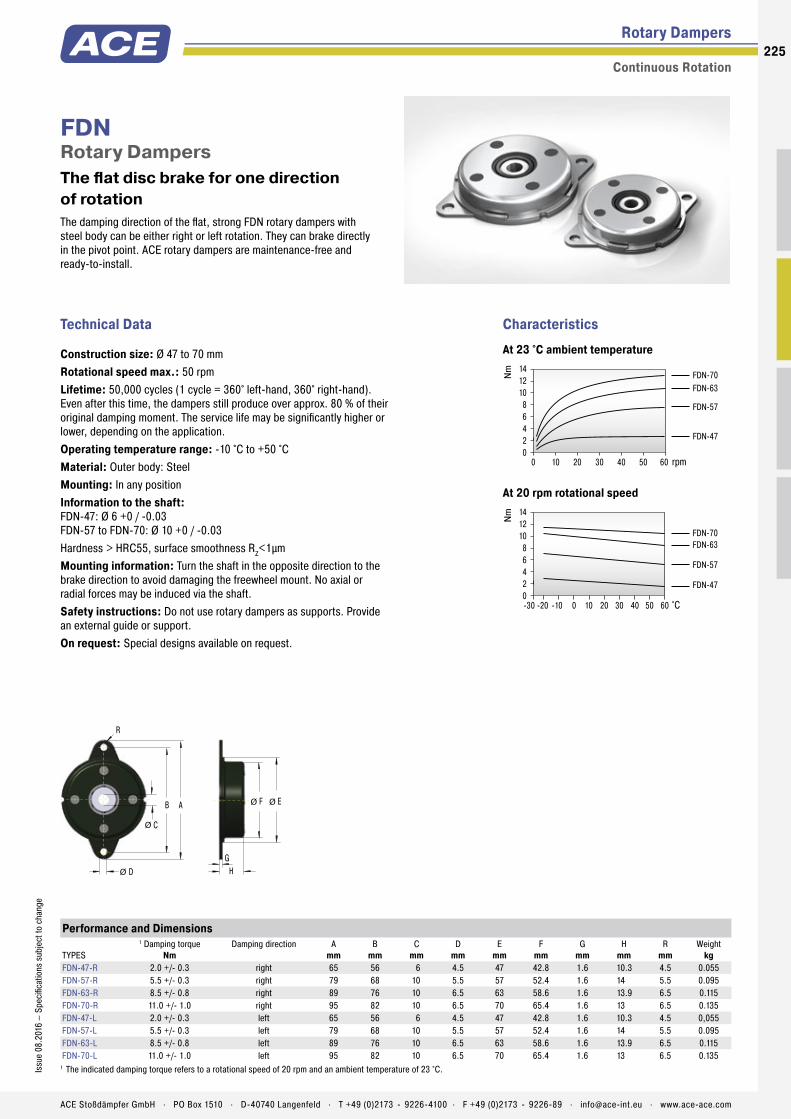
The damping direction of the flat, strong FDN rotary dampers with steel body can be either right or left rotation. They can brake directly in the pivot point. ACE rotary dampers are maintenance-free and ready-to-install.
FDNRotary Dampers The flat disc brake for one direction of rotation
Rotary Dampers
Continuous Rotation
Technical Data
Construction size: Ø 47 to 70 mmRotational speed max.: 50 rpmLifetime: 50,000 cycles (1 cycle = 360° left-hand, 360° right-hand). Even after this time, the dampers still produce over approx. 80 % of their original damping moment. The service life may be significantly higher or lower, depending on the application.Operating temperature range: -10 °C to +50 °CMaterial: Outer body: SteelMounting: In any positionInformation to the shaft: FDN-47: Ø 6 +0 / -0.03 FDN-57 to FDN-70: Ø 10 +0 / -0.03Hardness > HRC55, surface smoothness RZ<1µmMounting information: Turn the shaft in the opposite direction to the brake direction to avoid damaging the freewheel mount. No axial or radial forces may be induced via the shaft.Safety instructions: Do not use rotary dampers as supports. Provide an external guide or support.On request: Special designs available on request.
14121086420
FDN-70FDN-63
FDN-57
FDN-47
Nm
0 10 20 30 40 50 60 rpm
14121086420
FDN-70FDN-63
FDN-57
FDN-47
Nm
-30 -20 -10 0 10 20 30 40 50 60 °C
CharacteristicsAt 23 °C ambient temperature
At 20 rpm rotational speed
Performance and Dimensions
TYPES
1 Damping torqueNm
Damping direction Amm
Bmm
Cmm
Dmm
Emm
Fmm
Gmm
Hmm
Rmm
Weightkg
FDN-47-R 2.0 +/- 0.3 right 65 56 6 4.5 47 42.8 1.6 10.3 4.5 0.055FDN-57-R 5.5 +/- 0.3 right 79 68 10 5.5 57 52.4 1.6 14 5.5 0.095FDN-63-R 8.5 +/- 0.8 right 89 76 10 6.5 63 58.6 1.6 13.9 6.5 0.115FDN-70-R 11.0 +/- 1.0 right 95 82 10 6.5 70 65.4 1.6 13 6.5 0.135FDN-47-L 2.0 +/- 0.3 left 65 56 6 4.5 47 42.8 1.6 10.3 4.5 0,055FDN-57-L 5.5 +/- 0.3 left 79 68 10 5.5 57 52.4 1.6 14 5.5 0.095FDN-63-L 8.5 +/- 0.8 left 89 76 10 6.5 63 58.6 1.6 13.9 6.5 0.115FDN-70-L 11.0 +/- 1.0 left 95 82 10 6.5 70 65.4 1.6 13 6.5 0.135
1 The indicated damping torque refers to a rotational speed of 20 rpm and an ambient temperature of 23 °C.
AB
R
C
D
Ø
Ø H
E
G
FØ Ø
225Is
sue
08.2
016
– Sp
ecifi
catio
ns s
ubje
ct to
cha
nge
ACE Stoßdämpfer GmbH . PO Box 1510 . D-40740 Langenfeld . T +49 (0)2173 - 9226-4100 . F +49 (0)2173 - 9226-89 . [email protected] . www.ace-ace.com

The damping direction of the rotary damper FYN-P1 can be either right or left rotation. The dampers can be directly mounted in the pivot point. During each reverse movement of the unilateral decelerating versions there is a certain return damping torque that depends on the size. Differentiation of the damping direction through the coloured shaft. ACE rotary dampers are maintenance-free and ready-to-install.
FYN-P1Rotary Dampers Small diameter, large damping torques
Rotary Dampers
Partial Rotation Angle
Technical Data
Construction size: Ø 18.5 mmLifetime: 50,000 cycles, even after this time, the dampers still produce over approx. 80 % of their original damping moment. The service life may be significantly higher or lower, depending on the application.Operating temperature range: -5 °C to +50 °CMaterial: Outer body, Shaft: PlasticMounting: In any positionRotation angle max.: 115°Note: Damping direction: Right hand damping = damping action in clockwise direction (when looking onto the output shaft or output shaft sleeve, depending on the damper type). A play of approx. 5° can occur at the beginning of movement.Mounting information: No axial or radial forces may be induced via the shaft.Safety instructions: Do not use rotary dampers as supports. Provide an external guide or support.On request: Special designs available on request.
Performance
TYPESDamping torque
NcmReturn Damping Torque
NcmDamping direction Weight
kgFYN-P1-R103 100 30 right 0.011FYN-P1-R153 150 50 right 0.011FYN-P1-R183 180 80 right 0.011FYN-P1-L103 100 30 left 0.011FYN-P1-L153 150 50 left 0.011FYN-P1-L183 180 80 left 0.011
17.5
2214
5
4
18
18.5 12Ø Ø Ø115°20°Rotation
812
24
8
white shaft: left-hand dampingblack shaft: right-hand damping
226
Issu
e 08
.201
6 –
Spec
ifica
tions
sub
ject
to c
hang
e
ACE Stoßdämpfer GmbH . PO Box 1510 . D-40740 Langenfeld . T +49 (0)2173 - 9226-4100 . F +49 (0)2173 - 9226-89 . [email protected] . www.ace-ace.com
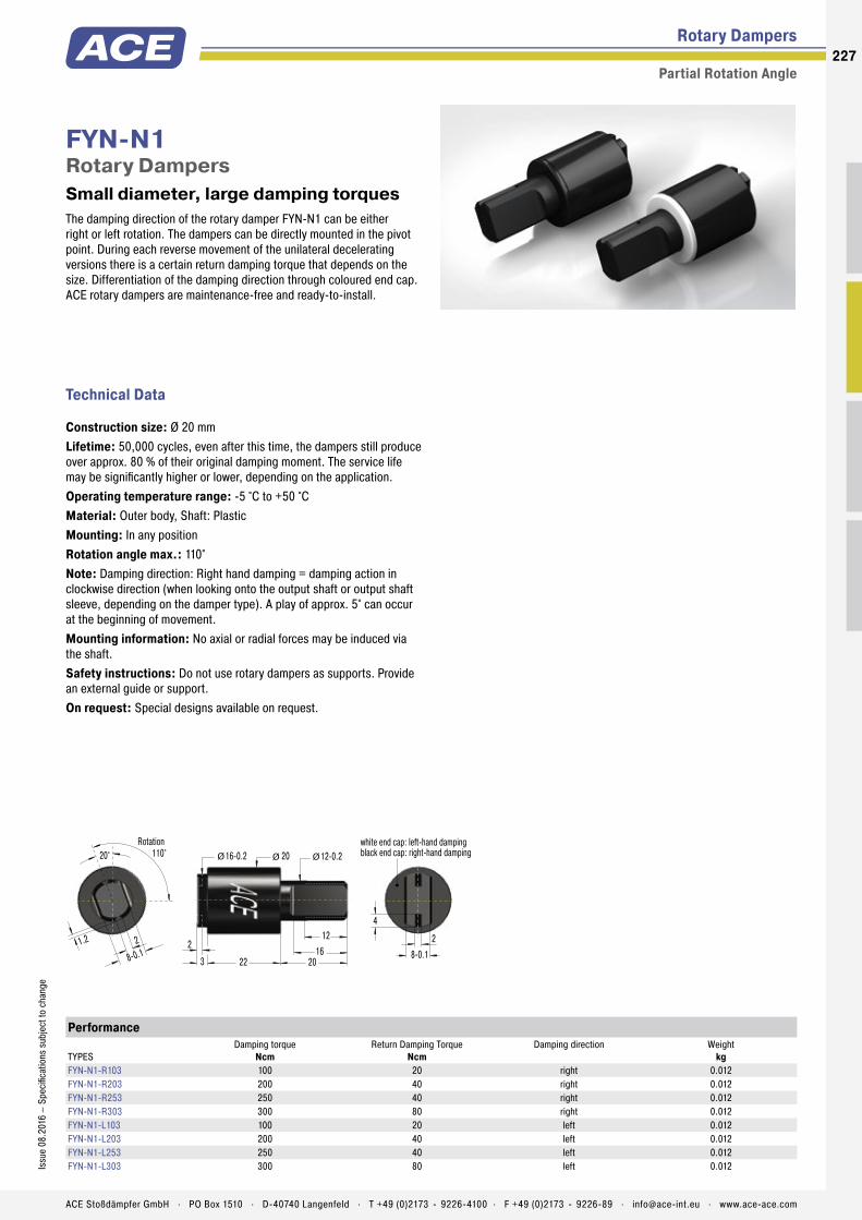
The damping direction of the rotary damper FYN-N1 can be either right or left rotation. The dampers can be directly mounted in the pivot point. During each reverse movement of the unilateral decelerating versions there is a certain return damping torque that depends on the size. Differentiation of the damping direction through coloured end cap. ACE rotary dampers are maintenance-free and ready-to-install.
FYN-N1Rotary Dampers Small diameter, large damping torques
Rotary Dampers
Partial Rotation Angle
Technical Data
Construction size: Ø 20 mmLifetime: 50,000 cycles, even after this time, the dampers still produce over approx. 80 % of their original damping moment. The service life may be significantly higher or lower, depending on the application.Operating temperature range: -5 °C to +50 °CMaterial: Outer body, Shaft: PlasticMounting: In any positionRotation angle max.: 110°Note: Damping direction: Right hand damping = damping action in clockwise direction (when looking onto the output shaft or output shaft sleeve, depending on the damper type). A play of approx. 5° can occur at the beginning of movement.Mounting information: No axial or radial forces may be induced via the shaft.Safety instructions: Do not use rotary dampers as supports. Provide an external guide or support.On request: Special designs available on request.
Performance
TYPESDamping torque
NcmReturn Damping Torque
NcmDamping direction Weight
kgFYN-N1-R103 100 20 right 0.012FYN-N1-R203 200 40 right 0.012FYN-N1-R253 250 40 right 0.012FYN-N1-R303 300 80 right 0.012FYN-N1-L103 100 20 left 0.012FYN-N1-L203 200 40 left 0.012FYN-N1-L253 250 40 left 0.012FYN-N1-L303 300 80 left 0.012
16-0.2
2216
3
2
20
20 12-0.2
12
ØØØ
2
4
8-0.1
white end cap: left-hand dampingblack end cap: right-hand damping110°20°
Rotation
1.2 2
8-0.1
227Is
sue
08.2
016
– Sp
ecifi
catio
ns s
ubje
ct to
cha
nge
ACE Stoßdämpfer GmbH . PO Box 1510 . D-40740 Langenfeld . T +49 (0)2173 - 9226-4100 . F +49 (0)2173 - 9226-89 . [email protected] . www.ace-ace.com

The damping direction of the rotary damper FYN-U1 can be either right or left rotation. The dampers can be directly mounted in the pivot point. The body is made of especially robust die-cast zinc. During each reverse movement of the unilateral decelerating versions there is a certain return damping torque that depends on the size. ACE rotary dampers are maintenance-free and ready-to-install.
FYN-U1Rotary Dampers Small, strong and very robust
Rotary Dampers
Partial Rotation Angle
Technical Data
Construction size: Ø 16 mmLifetime: 50,000 cycles, even after this time, the dampers still produce over approx. 80 % of their original damping moment. The service life may be significantly higher or lower, depending on the application.Operating temperature range: -5 °C to +50 °CMaterial: Outer body, Shaft: Zinc die-castMounting: In any positionRotation angle max.: 115°Note: Damping direction: Right hand damping = damping action in clockwise direction (when looking onto the output shaft or output shaft sleeve, depending on the damper type). A play of approx. 5° can occur at the beginning of movement.Mounting information: No axial or radial forces may be induced via the shaft.Safety instructions: Do not use rotary dampers as supports. Provide an external guide or support.On request: Special designs available on request.
Performance
TYPESDamping torque
NcmReturn Damping Torque
NcmDamping direction Weight
kgFYN-U1-R203 200 40 right 0.040FYN-U1-R253 250 40 right 0.040FYN-U1-R303 300 80 right 0.040FYN-U1-L203 200 40 left 0.040FYN-U1-L253 250 40 left 0.040FYN-U1-L303 300 80 left 0.040
20°Rotation
115°
610
345 18
10Ø16Ø13Ø
8
228
Issu
e 08
.201
6 –
Spec
ifica
tions
sub
ject
to c
hang
e
ACE Stoßdämpfer GmbH . PO Box 1510 . D-40740 Langenfeld . T +49 (0)2173 - 9226-4100 . F +49 (0)2173 - 9226-89 . [email protected] . www.ace-ace.com
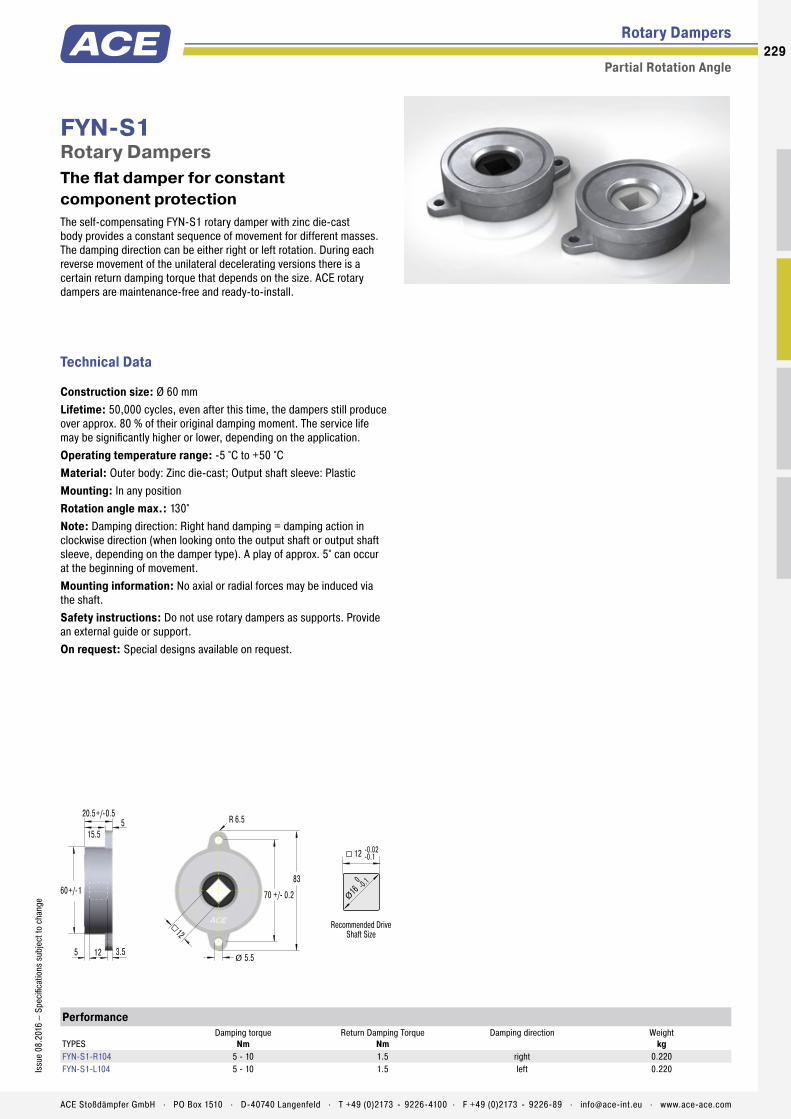
The self-compensating FYN-S1 rotary damper with zinc die-cast body provides a constant sequence of movement for different masses. The damping direction can be either right or left rotation. During each reverse movement of the unilateral decelerating versions there is a certain return damping torque that depends on the size. ACE rotary dampers are maintenance-free and ready-to-install.
FYN-S1Rotary Dampers The flat damper for constant component protection
Rotary Dampers
Partial Rotation Angle
Technical Data
Construction size: Ø 60 mmLifetime: 50,000 cycles, even after this time, the dampers still produce over approx. 80 % of their original damping moment. The service life may be significantly higher or lower, depending on the application.Operating temperature range: -5 °C to +50 °CMaterial: Outer body: Zinc die-cast; Output shaft sleeve: PlasticMounting: In any positionRotation angle max.: 130°Note: Damping direction: Right hand damping = damping action in clockwise direction (when looking onto the output shaft or output shaft sleeve, depending on the damper type). A play of approx. 5° can occur at the beginning of movement.Mounting information: No axial or radial forces may be induced via the shaft.Safety instructions: Do not use rotary dampers as supports. Provide an external guide or support.On request: Special designs available on request.
Performance
TYPESDamping torque
NmReturn Damping Torque
NmDamping direction Weight
kgFYN-S1-R104 5 - 10 1.5 right 0.220FYN-S1-L104 5 - 10 1.5 left 0.220
-0.02-0.1
0 -0.1
16Ø
Recommended DriveShaft Size
83
70 +/- 0.2
R 6.5
5.5Ø
12
60+/-1
15.5
3.5125
20.5+/-0.55
12
229Is
sue
08.2
016
– Sp
ecifi
catio
ns s
ubje
ct to
cha
nge
ACE Stoßdämpfer GmbH . PO Box 1510 . D-40740 Langenfeld . T +49 (0)2173 - 9226-4100 . F +49 (0)2173 - 9226-89 . [email protected] . www.ace-ace.com

The damping direction of the adjustable FYT-H1 and FYT-H1 can be right, left or two-sided rotation. During each reverse movement of the unilateral decelerating versions there is a certain return damping torque that depends on the size. The brakes have a particularly robust zinc die-cast body and shafts made of steel. ACE rotary dampers are maintenance-free and ready-to-install.
FYT-H1 and FYN-H1Rotary Dampers Specifically adjustable, strong braking force
Rotary Dampers
Partial Rotation Angle, Adjustable
Technical Data
Construction size: Ø 45 mmLifetime: 50,000 cycles, even after this time, the dampers still produce over approx. 80 % of their original damping moment. The service life may be significantly higher or lower, depending on the application.Operating temperature range: -5 °C to +50 °CMaterial: Outer body: Zinc die-cast; Shaft: SteelMounting: In any positionRotation angle max.: 105°Maximum side load: 50 NNote: Damping direction: Right hand damping = damping action in clockwise direction (when looking onto the output shaft or output shaft sleeve, depending on the damper type). A play of approx. 5° can occur at the beginning of movement.Safety instructions: Do not use rotary dampers as supports. Provide an external guide or support.On request: Special designs available on request.
Performance
TYPESDamping torque
NmReturn Damping Torque
NmDamping direction Weight
kgFYT-H1 2 - 10 0.5 bidirectional 0.235FYN-H1-R 2 - 10 0.5 right 0.235FYN-H1-L 2 - 10 0.5 left 0.235
Keyed output shaft shown in mid-travel position
11
5666
M5
105° Rotation
6 +/- 0.0545
2015 30
18
8
6
24P
Adjusting Screw
Ø
ØØ
230
Issu
e 08
.201
6 –
Spec
ifica
tions
sub
ject
to c
hang
e
ACE Stoßdämpfer GmbH . PO Box 1510 . D-40740 Langenfeld . T +49 (0)2173 - 9226-4100 . F +49 (0)2173 - 9226-89 . [email protected] . www.ace-ace.com
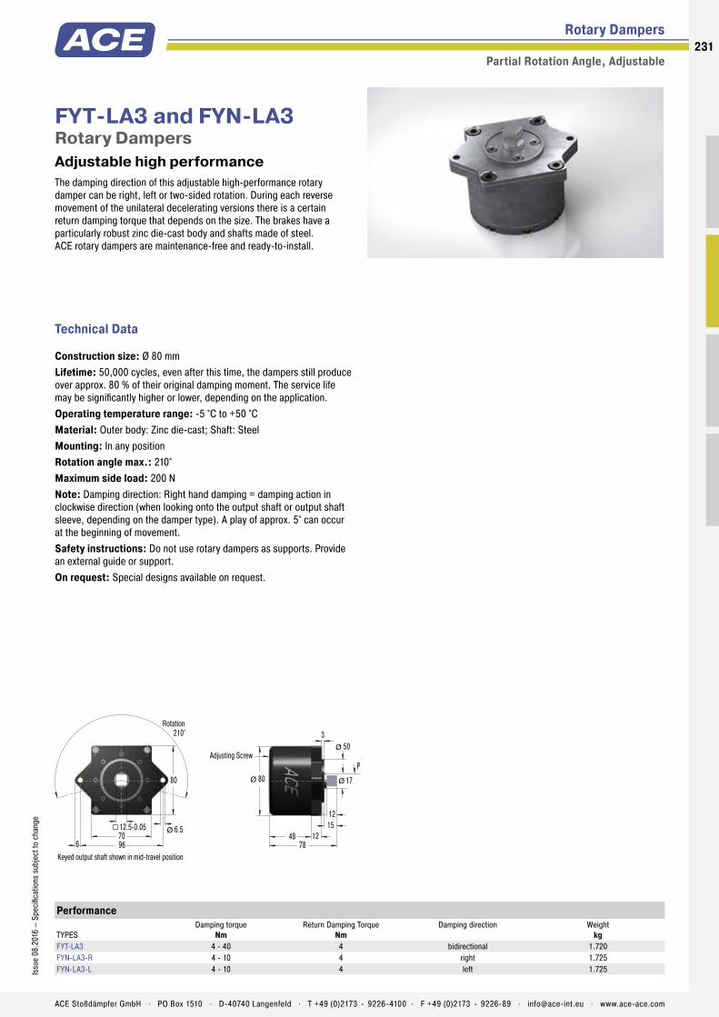
The damping direction of this adjustable high-performance rotary damper can be right, left or two-sided rotation. During each reverse movement of the unilateral decelerating versions there is a certain return damping torque that depends on the size. The brakes have a particularly robust zinc die-cast body and shafts made of steel. ACE rotary dampers are maintenance-free and ready-to-install.
FYT-LA3 and FYN-LA3Rotary Dampers Adjustable high performance
Rotary Dampers
Partial Rotation Angle, Adjustable
Technical Data
Construction size: Ø 80 mmLifetime: 50,000 cycles, even after this time, the dampers still produce over approx. 80 % of their original damping moment. The service life may be significantly higher or lower, depending on the application.Operating temperature range: -5 °C to +50 °CMaterial: Outer body: Zinc die-cast; Shaft: SteelMounting: In any positionRotation angle max.: 210°Maximum side load: 200 NNote: Damping direction: Right hand damping = damping action in clockwise direction (when looking onto the output shaft or output shaft sleeve, depending on the damper type). A play of approx. 5° can occur at the beginning of movement.Safety instructions: Do not use rotary dampers as supports. Provide an external guide or support.On request: Special designs available on request.
Performance
TYPESDamping torque
NmReturn Damping Torque
NmDamping direction Weight
kgFYT-LA3 4 - 40 4 bidirectional 1.720FYN-LA3-R 4 - 10 4 right 1.725FYN-LA3-L 4 - 10 4 left 1.725
Keyed output shaft shown in mid-travel position
80
70966
6.512.5-0.05
210°Rotation
Ø
1780
7848
3
121512
50
PAdjusting Screw
ØØ
Ø
231Is
sue
08.2
016
– Sp
ecifi
catio
ns s
ubje
ct to
cha
nge
ACE Stoßdämpfer GmbH . PO Box 1510 . D-40740 Langenfeld . T +49 (0)2173 - 9226-4100 . F +49 (0)2173 - 9226-89 . [email protected] . www.ace-ace.com
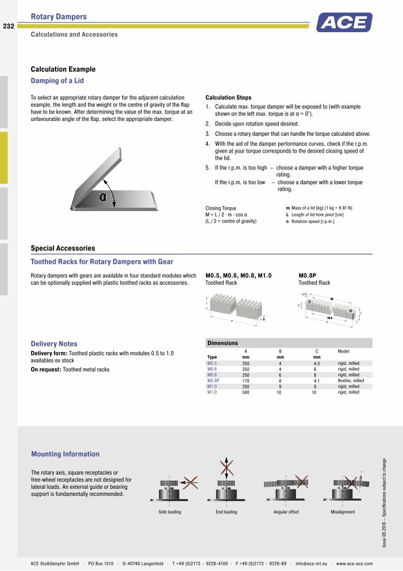
AA
C
BBAA
2,3
B
4,5
C
145,8
160Ø
α
Dimensions
TypeA
mmB
mmC
mmModel
M0.5 250 4 4.5 rigid, milledM0.6 250 4 6 rigid, milledM0.8 250 6 8 rigid, milledM0.8P 170 8 4.1 fl exible, milledM1.0 250 9 9 rigid, milledM1.0 500 10 10 rigid, milled
Rotary Dampers
Calculations and Accessories
Toothed Racks for Rotary Dampers with Gear
Calculation Steps1. Calculate max. torque damper will be exposed to (with example
shown on the left max. torque is at α = 0°).
2. Decide upon rotation speed desired.
3. Choose a rotary damper that can handle the torque calculated above.
4. With the aid of the damper performance curves, check if the r.p.m. given at your torque corresponds to the desired closing speed of the lid.
5. If the r.p.m. is too high – choose a damper with a higher torque rating.
If the r.p.m. is too low – choose a damper with a lower torque rating.
Mounting Information
The rotary axis, square receptacles or free-wheel receptacles are not designed for lateral loads. An external guide or bearing support is fundamentally recommended.
Rotary dampers with gears are available in four standard modules which can be optionally supplied with plastic toothed racks as accessories.
Closing TorqueM = L / 2 · m · cos α(L / 2 = centre of gravity)
m Mass of a lid [kg] (1 kg = 9.81 N)L Length of lid from pivot [cm]n Rotation speed [r.p.m.]
Delivery NotesDelivery form: Toothed plastic racks with modules 0.5 to 1.0 availables ex stockOn request: Toothed metal racks
To select an appropriate rotary damper for the adjacent calculation example, the length and the weight or the centre of gravity of the fl ap have to be known. After determining the value of the max. torque at an unfavourable angle of the fl ap, select the appropriate damper.
Calculation Example Damping of a Lid
M0.8PToothed Rack
M0.5, M0.6, M0.8, M1.0Toothed Rack
Special Accessories
Side loading End loading Angular offset Misalignment
232
Issu
e 08
.201
6 –
Spec
ifi ca
tions
sub
ject
to c
hang
e
ACE Stoßdämpfer GmbH . PO Box 1510 . D-40740 Langenfeld . T +49 (0)2173 - 9226-4100 . F +49 (0)2173 - 9226-89 . [email protected] . www.ace-ace.com

Application Examples
Rotary Dampers
FDT
Finger protection when cutting breadTo exclude the possibility of injury when using bread slicing machines on self-service counters, the automatic bread slicing process does not start until the fl ap of the modern machine is closed. To simplify the operation and to thereby increase acceptance of the self-slicing principle among users, two-way rotary dampers of the type FDT-57 ensure smooth opening and closing of the door. Even when rotary dampers must act only in one direction, ACE has appropriate variants readily available.
Protective fl aps secured with rotary dampers: the simple operation of bread slicing machines can then be easily managed by hand Daub Bakery Machinery BV, 5050 AB Goirle, Netherlands
FDN-R
Invisible protection for cooker hoodsFor ergonomic handling, modern cooker hoods can be driven by a motor into an up position and then down again. When driven downwards, an AC load can result in a total loss through current being fed back into the voltage source. One of the tasks of the ACE rotary dampers type FDN-63-R is to prevent this. The modern machine elements are also built to provide protection against motor failure. Sliding the hood down too quickly could lead to further costly damage to the hood and the ceiling console and even cause personal injury.
Rotary dampers in high-end cooker hoods safeguard the protection of drive units and protect chefs, even during power failures berbel Ablufttechnik GmbH, 48432 Rheine, Germany
233Is
sue
08.2
016
– Sp
ecifi
catio
ns s
ubje
ct to
cha
nge
ACE Stoßdämpfer GmbH . PO Box 1510 . D-40740 Langenfeld . T +49 (0)2173 - 9226-4100 . F +49 (0)2173 - 9226-89 . [email protected] . www.ace-ace.com

Vibration ControlVibration-Isolating Pads Rubber-Metal Isolators
Low Frequency Pneumatic Levelling Mounts

Isolate Unwanted Vibrations Effectively Unique variety
This product group from ACE includes innovative solutions to provide customers with the best assistance in insulation tech-nology and vibration isolation. These machine elements are also distinguished by their light design and exemplary variety.
The product range extends from extremely low frequency isolating pneumatic levelling mounts through to ready-to-install rubber-metal isolators and insulation plates. With this portfolio, ACE is capable of offering you customised vibration isolation and all almost any applications.

236236
ACE Stoßdämpfer GmbH . PO Box 1510 . D-40740 Langenfeld . T +49 (0)2173 - 9226-4100 . [email protected] . www.ace-ace.comACE Stoßdämpfer GmbH . PO Box 1510 . D-40740 Langenfeld . T +49 (0)2173 - 9226-4100 . [email protected] . www.ace-ace.com
Vibration Isolation
Noise reduction and vibration isolation are becoming more and more important in our daily lives. This applies in particular to the workplace and the environments around production companies.
Preventing noise emissions or harmful vibrations is therefore not only a necessity required by noise protection and occupational health and safety legislation; their sources must also be localised by means of targeted analyses in order to develop suitable improvement measures for achieving, for example, increased production quality. A second by-product of vibrations are their effects on the surrounding production environment and any measuring and testing facilities that may be in use.
Advantages and function
• improved working conditions for people and the environment
• more accurate production tolerances and thereby increased product quality
• competitive and cost advantages thanks to lower reject rate in production
• increased production speed thanks to increased maximum machine dynamics
• longer tool and machine life thanks to lower stress
• faster and more accurate measuring results
Vibration Control
For detailed information see special catalogueACEolator
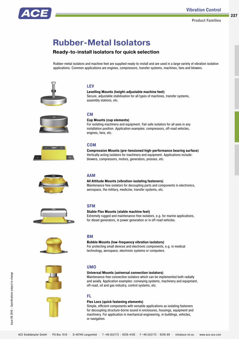
237Is
sue
08.2
016
– Sp
ecifi
catio
ns s
ubje
ct to
cha
nge
ACE Stoßdämpfer GmbH . PO Box 1510 . D-40740 Langenfeld . T +49 (0)2173 - 9226-4100 . F +49 (0)2173 - 9226-89 . [email protected] . www.ace-ace.com
Rubber-Metal IsolatorsReady-to-install isolators for quick selection
LEV Levelling Mounts (height-adjustable machine feet) Secure, adjustable stabilisation for all types of machines, transfer systems, assembly stations, etc.
CM Cup Mounts (cup elements) For isolating machinery and equipment. Fail-safe isolators for all axes in any installation position. Application examples: compressors, off-road vehicles, engines, fans, etc.
COM Compression Mounts (pre-tensioned high-performance bearing surface) Vertically acting isolators for machinery and equipment. Applications include: blowers, compressors, motors, generators, presses, etc.
AAM All Attitude Mounts (vibration-isolating fasteners) Maintenance free isolators for decoupling parts and components in electronics, aerospace, the military, medicine, transfer systems, etc.
SFM Stable Flex Mounts (stable machine feet) Extremely rugged and maintenance-free isolators, e.g. for marine applications, for diesel generators, in power generation or in off-road vehicles.
BM Bubble Mounts (low-frequency vibration isolators) For protecting small devices and electronic components, e.g. in medical technology, aerospace, electronic systems or computers.
UMO Universal Mounts (universal connection isolators) Maintenance-free connection isolators which can be implemented both radially and axially. Application examples: conveying systems, machinery and equipment, off-road, oil and gas industry, control systems, etc.
FL Flex Locs (quick fastening elements) Simple, efficient components with versatile applications as isolating fasteners for decoupling structure-borne sound in enclosures, housings, equipment and machinery. For application in mechanical engineering, in buildings, vehicles, or navigation.
Rubber-metal isolators and machine feet are supplied ready-to-install and are used in a large variety of vibration isolation applications. Common applications are engines, compressors, transfer systems, machines, fans and blowers.
Vibration Control
Product Families
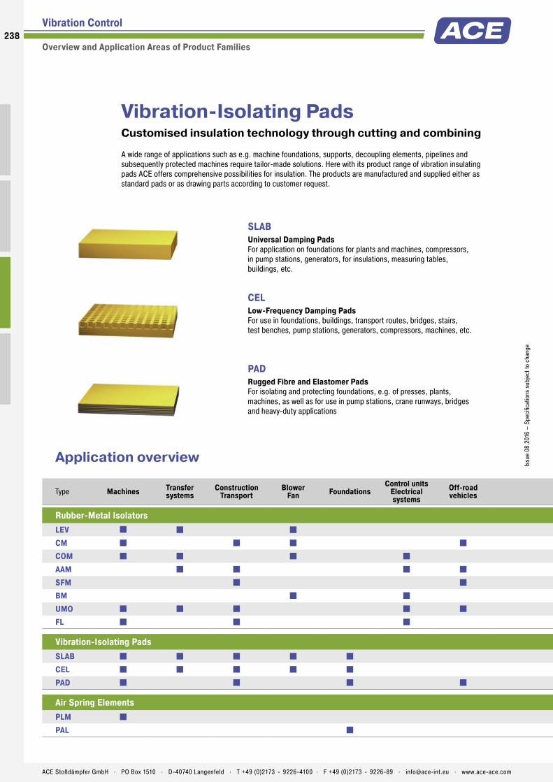
238
Issu
e 08
.201
6 –
Spec
ifica
tions
sub
ject
to c
hang
e
ACE Stoßdämpfer GmbH . PO Box 1510 . D-40740 Langenfeld . T +49 (0)2173 - 9226-4100 . F +49 (0)2173 - 9226-89 . [email protected] . www.ace-ace.com
Issu
e 08
.201
6 –
Spec
ifica
tions
sub
ject
to c
hang
e
Vibration-Isolating PadsCustomised insulation technology through cutting and combining
A wide range of applications such as e.g. machine foundations, supports, decoupling elements, pipelines and subsequently protected machines require tailor-made solutions. Here with its product range of vibration insulating pads ACE offers comprehensive possibilities for insulation. The products are manufactured and supplied either as standard pads or as drawing parts according to customer request.
Vibration Control
Overview and Application Areas of Product Families
SLABUniversal Damping Pads For application on foundations for plants and machines, compressors, in pump stations, generators, for insulations, measuring tables, buildings, etc.
CEL Low-Frequency Damping Pads For use in foundations, buildings, transport routes, bridges, stairs, test benches, pump stations, generators, compressors, machines, etc.
PAD Rugged Fibre and Elastomer Pads For isolating and protecting foundations, e.g. of presses, plants, machines, as well as for use in pump stations, crane runways, bridges and heavy-duty applications
Type Machines Transfer systems
ConstructionTransport
BlowerFan Foundations
Control unitsElectrical systems
Off-roadvehicles
EnginesGenerators Compressors Oil and
gas industryAerospace
engineering Presses Medicine Measuringtables
Testbenches Type
Rubber-Metal Isolators Rubber-Metal IsolatorsLEV LEVCM CMCOM COMAAM AAMSFM SFMBM BMUMO UMOFL FL
Vibration-Isolating Pads Vibration-Isolating PadsSLAB SLABCEL CELPAD PAD
Air Spring Elements Air Spring ElementsPLM PLMPAL PAL
Application overview

239Is
sue
08.2
016
– Sp
ecifi
catio
ns s
ubje
ct to
cha
nge
ACE Stoßdämpfer GmbH . PO Box 1510 . D-40740 Langenfeld . T +49 (0)2173 - 9226-4100 . F +49 (0)2173 - 9226-89 . [email protected] . www.ace-ace.com
Issu
e 08
.201
6 –
Spec
ifica
tions
sub
ject
to c
hang
eVibration Control
Overview and Application Areas of Product Families
Low Frequency Pneumatic Levelling MountsHighly efficient insulation – it can hardly get any deeper
Everywhere where perfect isolation of measuring tables, test equipment and high-performance machines are important the low frequency pneumatic levelling mounts PLM and PAL are a good choice. On request a detailed system analysis will be carried out at the customer and the perfect solution will be developed.
PLMPneumatic Air Spring Elements For an efficient isolation of measuring equipment, high-speed presses and machines.
PAL Air Spring Elements with Automatic Level Controls Isolation against disruptive vibrations and level-adjustment for test and measuring equipment. Isolating at extremely low-frequencies, these components are used in the automotive industry and in aerospace engineering.
Type Machines Transfer systems
ConstructionTransport
BlowerFan Foundations
Control unitsElectrical systems
Off-roadvehicles
EnginesGenerators Compressors Oil and
gas industryAerospace
engineering Presses Medicine Measuringtables
Testbenches Type
Rubber-Metal Isolators Rubber-Metal IsolatorsLEV LEVCM CMCOM COMAAM AAMSFM SFMBM BMUMO UMOFL FL
Vibration-Isolating Pads Vibration-Isolating PadsSLAB SLABCEL CELPAD PAD
Air Spring Elements Air Spring ElementsPLM PLMPAL PAL
More information about Vibration Control can be found in our special catalog and on our homepage www.ace-ace.com / Downloads

Safety ProductsSafety Shock Absorbers, Safety Dampers
Clamping Elements
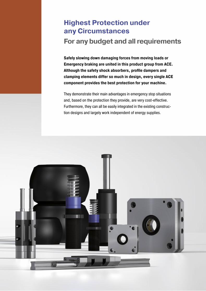
Highest Protection under any Circumstances For any budget and all requirements
Safely slowing down damaging forces from moving loads or Emergency braking are united in this product group from ACE. Although the safety shock absorbers, profile dampers and clamping elements differ so much in design, every single ACE component provides the best protection for your machine.
They demonstrate their main advantages in emergency stop situations and, based on the protection they provide, are very cost-effective. Furthermore, they can all be easily integrated in the existing construc-tion designs and largely work independent of energy supplies.

Safety Shock AbsorbersPerfect protection for the worst case scenario
As a cheaper alternative to the standard shock absorber, Safety shock absorbers are the tried and tested low cost metrhod of preventing those occasional emergency stops. Designed for occasional use, they primarily serve as reliable, effective protection in emergency stopping for construction designs.
The maintenance-free and ready-to-install machine elements are characterised in every respect by the well-known high ACE quality and maximum energy absorption of up to 480,000 Nm/Cycle. This means, in the product-family SCS33 up to SCS64 a service life of up to 1,000 full load emergency cycles is achieved. Safety shock absorbers from ACE are available in a large choice with strokes of 23 to 1,200 mm, and the arrangement of orifi ce pattern can be calculated and produced specifi cally to the customer‘s requirements and depending on the application.
Safety Products242242
ACE Stoßdämpfer GmbH . PO Box 1510 . D-40740 Langenfeld . T +49 (0)2173 - 9226-4100 . [email protected] . www.ace-ace.com
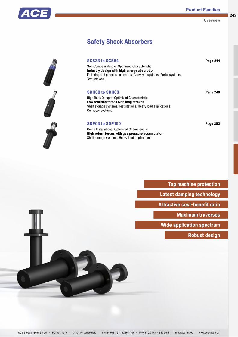
Product Families
Overview
Safety Shock Absorbers
SCS33 to SCS64 Self-Compensating or Optimized Characteristic Industry design with high energy absorptionFinishing and processing centres, Conveyor systems, Portal systems, Test stations
Page 244
SDH38 to SDH63 High Rack Damper, Optimized Characteristic Low reaction forces with long strokesShelf storage systems, Test stations, Heavy load applications, Conveyor systems
Page 248
SDP63 to SDP160 Crane Installations, Optimized Characteristic High return forces with gas pressure accumulatorShelf storage systems, Heavy load applications
Page 252
Top machine protection
Latest damping technology
Attractive cost-benefi t ratio
Robust design
Maximum traverses
Wide application spectrum
243
ACE Stoßdämpfer GmbH . PO Box 1510 . D-40740 Langenfeld . T +49 (0)2173 - 9226-4100 . F +49 (0)2173 - 9226-89 . [email protected] . www.ace-ace.com

Piston Rod
Positive Stop
Pressure Chamber with Metering Orifices
Rod Button
Seals
Piston
Outer Body
Main Bearing
Membrane Accumulator
Piston Ring
One-Piece Outer Body without Retaining Ring
Technical Data
Effective emergency stop: The ACE safety shock absorbers from the SCS33 to 64 Series are based on the innovative technology of the successful industrial shock absorbers from the MAGNUM-Series. They are also maintenance-free and ready-to-install.
Due to the optimised characteristic curve for the respective application, the energy absorption of these hydraulic machine elements can be increased to more than twice the level of the MAGNUM model of ACE industrial shock absorber per stroke. Users benefi t from a service life of up to 1,000 full load emergency cycles with a very good price-performance ratio. Their compact design in sizes M33x1.5 to M64x2 makes them easy to integrate into current applications.
These slimline, high-performance safety shock absorbers are only designed for emergency stop situations. They can be used for a number of tasks in gantries and conveyor systems, processing centres or assembly machines.
SCS33 to SCS64Safety Shock Absorbers Industry design with high energy absorption
Safety Shock Absorbers
Self-Compensating or Optimized Characteristic
Energy capacity: 310 Nm/Cycle to 18,000 Nm/CycleImpact velocity range: 0.02 m/s to 5 m/s. Other speeds on request.Operating temperature range: -12 °C to +66 °C. Other temperatures on request.Mounting: In any positionPositive stop: IntegratedMaterial: Outer body: Nitride hardened steel; Piston rod: Hard chrome plated steel; Rod end button: Hardened steel and corrosion-resistant coating; Return spring: Zinc plated or
plastic-coated steel; Accessories: Steel corrosion-resistant coatingDamping medium: Automatic Transmission Fluid (ATF)Application fi eld: Finishing and processing centres, Conveyor systems, Portal systems, Test stationsNote: The shock absorber can be pushed through its stroke. In creep speed conditions the shock absorber provides minimal resistance and there is no braking effect.On request: Special oils, special fl anges etc.
244
Issu
e 08
.201
6 –
Spec
ifi ca
tions
sub
ject
to c
hang
e
ACE Stoßdämpfer GmbH . PO Box 1510 . D-40740 Langenfeld . T +49 (0)2173 - 9226-4100 . F +49 (0)2173 - 9226-89 . [email protected] . www.ace-ace.com
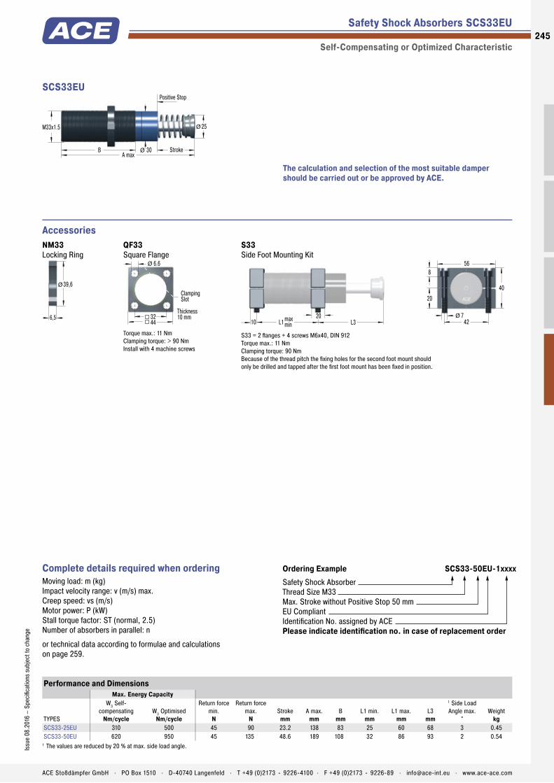
Piston Rod
Positive Stop
Pressure Chamber with Metering Orifices
Rod Button
Seals
Piston
Outer Body
Main Bearing
Membrane Accumulator
Piston Ring
One-Piece Outer Body without Retaining Ring
Safety Shock Absorbers SCS33EU
Self-Compensating or Optimized Characteristic
M33x1.5
Positive Stop
Stroke30
25
BA max
Ø
Ø
SCS33EU
Accessories
The calculation and selection of the most suitable damper should be carried out or be approved by ACE.
Performance and DimensionsMax. Energy Capacity
TYPES
W3 Self-compensating
Nm/cycleW3 Optimised
Nm/cycle
Return force min.
N
Return force max.
NStroke
mmA max.
mmB
mmL1 min.
mmL1 max.
mmL3
mm
1 Side Load Angle max.
°Weight
kgSCS33-25EU 310 500 45 90 23.2 138 83 25 60 68 3 0.45SCS33-50EU 620 950 45 135 48.6 189 108 32 86 93 2 0.54
1 The values are reduced by 20 % at max. side load angle.
Ordering Example SCS33-50EU-1xxxxSafety Shock AbsorberThread Size M33Max. Stroke without Positive Stop 50 mmEU CompliantIdentification No. assigned by ACEPlease indicate identification no. in case of replacement order
Complete details required when ordering Moving load: m (kg)Impact velocity range: v (m/s) max.Creep speed: vs (m/s)Motor power: P (kW)Stall torque factor: ST (normal, 2.5)Number of absorbers in parallel: n
or technical data according to formulae and calculations on page 259.
NM33 Locking Ring
6,5
39,6Ø
QF33 Square Flange
44
Thickness10 mm
ClampingSlot
32
6.6Ø
Torque max.: 11 NmClamping torque: > 90 NmInstall with 4 machine screws
S33 Side Foot Mounting Kit
L1 L31020max
min
8
742
56
20
Ø
40
S33 = 2 fl anges + 4 screws M6x40, DIN 912Torque max.: 11 NmClamping torque: 90 NmBecause of the thread pitch the fi xing holes for the second foot mount should only be drilled and tapped after the fi rst foot mount has been fi xed in position.
245Is
sue
08.2
016
– Sp
ecifi
catio
ns s
ubje
ct to
cha
nge
ACE Stoßdämpfer GmbH . PO Box 1510 . D-40740 Langenfeld . T +49 (0)2173 - 9226-4100 . F +49 (0)2173 - 9226-89 . [email protected] . www.ace-ace.com
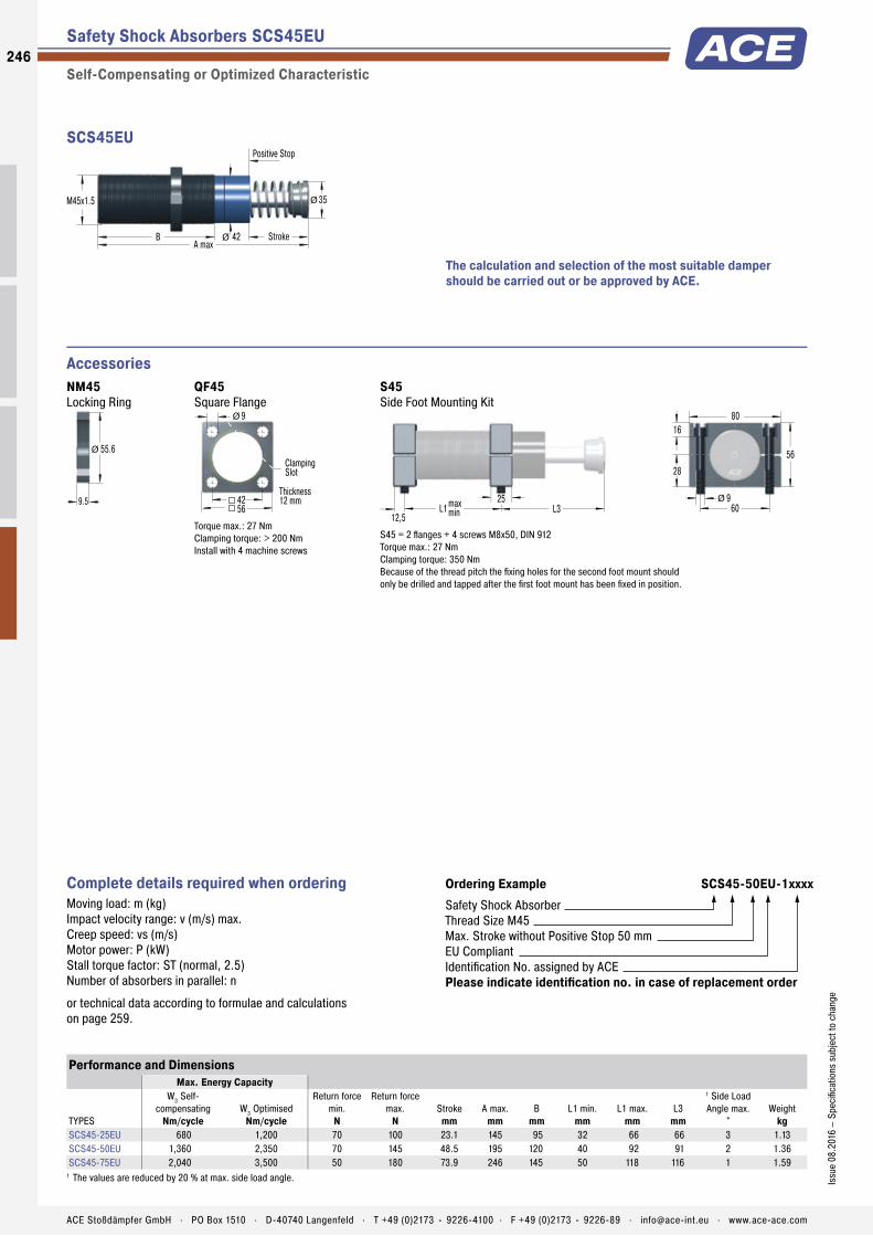
Safety Shock Absorbers SCS45EU
Self-Compensating or Optimized Characteristic
M45x1.5
Positive Stop
Stroke42
35
BA max
Ø
Ø
SCS45EU
Accessories
The calculation and selection of the most suitable damper should be carried out or be approved by ACE.
Performance and DimensionsMax. Energy Capacity
TYPES
W3 Self-compensating
Nm/cycleW3 Optimised
Nm/cycle
Return force min.
N
Return force max.
NStroke
mmA max.
mmB
mmL1 min.
mmL1 max.
mmL3
mm
1 Side Load Angle max.
°Weight
kgSCS45-25EU 680 1,200 70 100 23.1 145 95 32 66 66 3 1.13SCS45-50EU 1,360 2,350 70 145 48.5 195 120 40 92 91 2 1.36SCS45-75EU 2,040 3,500 50 180 73.9 246 145 50 118 116 1 1.59
1 The values are reduced by 20 % at max. side load angle.
Ordering Example SCS45-50EU-1xxxxSafety Shock AbsorberThread Size M45Max. Stroke without Positive Stop 50 mmEU CompliantIdentification No. assigned by ACEPlease indicate identification no. in case of replacement order
Complete details required when ordering Moving load: m (kg)Impact velocity range: v (m/s) max.Creep speed: vs (m/s)Motor power: P (kW)Stall torque factor: ST (normal, 2.5)Number of absorbers in parallel: n
or technical data according to formulae and calculations on page 259.
NM45 Locking Ring
9.5
55.6Ø
QF45 Square Flange
56
Thickness12 mm
ClampingSlot
42
9Ø
Torque max.: 27 NmClamping torque: > 200 NmInstall with 4 machine screws
S45 Side Foot Mounting Kit
L1 L312,5
25maxmin
16
960
80
28
Ø
56
S45 = 2 fl anges + 4 screws M8x50, DIN 912Torque max.: 27 NmClamping torque: 350 NmBecause of the thread pitch the fi xing holes for the second foot mount should only be drilled and tapped after the fi rst foot mount has been fi xed in position.
246
Issu
e 08
.201
6 –
Spec
ifi ca
tions
sub
ject
to c
hang
e
ACE Stoßdämpfer GmbH . PO Box 1510 . D-40740 Langenfeld . T +49 (0)2173 - 9226-4100 . F +49 (0)2173 - 9226-89 . [email protected] . www.ace-ace.com

Safety Shock Absorbers SCS64EU
Self-Compensating or Optimized Characteristic
M64x2
Positive Stop
Stroke
Note: 150 mm stroke model does not include stop collar and positive stop is provided by the rod button (Ø 60 mm)
60
48
BA max
Ø
Ø
SCS64EU
Accessories
The calculation and selection of the most suitable damper should be carried out or be approved by ACE.
Performance and DimensionsMax. Energy Capacity
TYPES
W3 Self-compensating
Nm/cycleW3 Optimised
Nm/cycle
Return force min.
N
Return force max.
NStroke
mmA max.
mmB
mmL1 min.
mmL1 max.
mmL3
mm
1 Side Load Angle max.
°Weight
kgSCS64-50EU 3,400 6,000 90 155 48.6 225 140 50 112 100 3 2.9SCS64-100EU 6,800 12,000 105 270 99.4 326 191 64 162 152 2 4.2SCS64-150EU 10,200 18,000 75 365 150.0 450 241 80 212 226 1 5.1
1 The values are reduced by 20 % at max. side load angle.
Ordering Example SCS64-50EU-1xxxxSafety Shock AbsorberThread Size M64Max. Stroke without Positive Stop 50 mmEU CompliantIdentification No. assigned by ACEPlease indicate identification no. in case of replacement order
Complete details required when ordering Moving load: m (kg)Impact velocity range: v (m/s) max.Creep speed: vs (m/s)Motor power: P (kW)Stall torque factor: ST (normal, 2.5)Number of absorbers in parallel: n
or technical data according to formulae and calculations on page 259.
NM64 Locking Ring
9.5
76Ø
QF64 Square Flange
80
Thickness16 mm
ClampingSlot
58
11Ø
Torque max.: 50 NmClamping torque: > 210 NmInstall with 4 machine screws
S64 Side Foot Mounting Kit
L1 L312,5
25maxmin
12
11,578
100
40
Ø
80
S64 = 2 fl anges + 4 screws M10x80, DIN 912Torque max.: 50 NmClamping torque: 350 NmBecause of the thread pitch the fi xing holes for the second foot mount should only be drilled and tapped after the fi rst foot mount has been fi xed in position.
247Is
sue
08.2
016
– Sp
ecifi
catio
ns s
ubje
ct to
cha
nge
ACE Stoßdämpfer GmbH . PO Box 1510 . D-40740 Langenfeld . T +49 (0)2173 - 9226-4100 . F +49 (0)2173 - 9226-89 . [email protected] . www.ace-ace.com

Piston Rod
Gas Accumulator
Positive Stop
Rod Button
Seals
Piston
Outer Body
Main Bearing
Pressure Chamber with Metering Orifices
Membran
Technical Data
Intelligent protective measure: The safety shock absorbers from the SDH38 to 63 series are also designed for emergency-stop applications. Strokes of up to 1,200 mm are possible with these maintenance-free and ready-to-install dampers. Low support forces result due to the large strokes.
The characteristic curve or damping characte-ristics of all safety shock absorbers from ACE is individually adjusted to the respective application, specifi c to the customer. The metering orifices for the respective application are specially calculated and produced. These tailor-made machine elements are the ideal protection because they are less expensive than industrial shock absorbers and are effective with up to 1,000 maximum full load emergency cycles possible.
Anyone who wants to reliably protect the end positions of rack operating equipment, conveyor and crane systems, heavy duty applications and test benches chooses these safety shock absorbers from ACE.
SDH38 to SDH63Safety Shock Absorbers Low reaction forces with long strokes
Safety Shock Absorbers
High Rack Damper, Optimized Characteristic
Energy capacity: 3,600 Nm/Cycle to 229,100 Nm/CycleImpact velocity range: 0.5 m/s to 4.6 m/s. Other speeds on request.Reacting force: At max. capacity rating = 51 kN to 210 kNOperating temperature range: -20 °C to +60 °C. Other temperatures on request.Mounting: In any positionPositive stop: IntegratedMaterial: Outer body: Painted steel; Piston rod: Hard chrome plated steel; Rod end button: Steel
Damping medium: HLP 46Filling pressure: Approx. 5 bar. Rod return by integrated nitogen accumulator.Application fi eld: Shelf storage systems, Test stations, Heavy load applications, Conveyor systemsNote: For creep speed applications, please consult ACE.On request: Special oils, special fl anges, additional corrosion protection etc. Integrated rod sensor for indicating the complete extension of the piston rod. Type normally closed or normally open, option PNP or NPN switch.
248
Issu
e 08
.201
6 –
Spec
ifi ca
tions
sub
ject
to c
hang
e
ACE Stoßdämpfer GmbH . PO Box 1510 . D-40740 Langenfeld . T +49 (0)2173 - 9226-4100 . F +49 (0)2173 - 9226-89 . [email protected] . www.ace-ace.com

Piston Rod
Gas Accumulator
Positive Stop
Rod Button
Seals
Piston
Outer Body
Main Bearing
Pressure Chamber with Metering Orifices
Membran
Performance and DimensionsMounting Style
TYPES
1 Energy capacityNm/cycle
1 Reacting forceN
Return force min.N
Return force max.N
Strokemm
A max.mm
Bmm
Dmm
E max.mm
F and RWeight
kg
SWeight
kgSDH38-50EU 3,600 80,000 600 700 50 270 204 165 84 13.5 13.7SDH38-100EU 7,300 80,000 600 700 100 370 254 215 134 15.5 15.7SDH38-150EU 10,900 80,000 600 700 150 470 304 265 184 17.0 17.2SDH38-200EU 14,500 80,000 600 700 200 585 369 330 234 19.5 19.7SDH38-250EU 18,200 80,000 600 700 250 685 419 380 284 21.5 21.7SDH38-300EU 21,800 80,000 600 700 300 800 484 445 334 23.5 23.7SDH38-350EU 25,500 80,000 600 700 350 900 534 495 384 25.5 25.7SDH38-400EU 29,100 80,000 600 700 400 1,015 599 560 434 28.0 28.2SDH38-500EU 36,400 80,000 600 700 500 1,230 714 675 534 32.0 32.2SDH38-600EU 43,600 80,000 600 700 600 1,445 829 790 634 36.0 36.2SDH38-700EU 50,900 80,000 600 700 700 1,660 944 905 734 40.0 40.2SDH38-800EU 58,200 80,000 600 700 800 1,875 1,059 1,020 834 44.0 44.2
1 The values apply to mounting style Front Flange and Foot Mounting. For mounting style Rear Flange, please consult ACE.In case of an existing side load angle, please consult ACE.
Safety Shock Absorbers SDH38EU
High Rack Damper, Optimized Characteristic
Ordering Example SDH38-400EU-F-XXXXXSafety Shock AbsorberBore Size Ø 38 mmStroke 400 mmEU CompliantMounting Style: Front FlangeIdentification No. assigned by ACEPlease indicate identification no. in case of replacement order
Complete details required when ordering Moving load: m (kg)Impact velocity range: v (m/s) max.Creep speed: vs (m/s)Motor power: P (kW)Stall torque factor: ST (normal, 2.5)Number of absorbers in parallel: n
or technical data according to formulae and calculations on page 259.
The calculation and selection of the most suitable damper should be carried out or be approved by ACE.
Technical Data
Impact velocity range: 0.9 m/s to 4.6 m/s
5520
B StrokeA max
15
Ø
120160
18Ø 115Ø 36Ø
SDH38EU-F Front Flange
5520
B StrokeA max
15
Ø
120160
18Ø 115Ø 36Ø
SDH38EU-R Rear Flange
30
D ± 1 E max
Stroke
A max
15
30
160190
18Ø
61
60 36
115Ø 36Ø 55Ø
SDH38EU-S Foot Mount
249Is
sue
08.2
016
– Sp
ecifi
catio
ns s
ubje
ct to
cha
nge
ACE Stoßdämpfer GmbH . PO Box 1510 . D-40740 Langenfeld . T +49 (0)2173 - 9226-4100 . F +49 (0)2173 - 9226-89 . [email protected] . www.ace-ace.com

Performance and DimensionsMounting Style
TYPES
1 Energy capacityNm/cycle
1 Reacting forceN
Return force min.N
Return force max.N
Strokemm
A max.mm
Bmm
Dmm
E max.mm
F and RWeight
kg
SWeight
kgSDH50-100EU 14,500 160,000 1,000 1,200 100 416 297 258 139 23.5 25.0SDH50-150EU 21,800 160,000 1,000 1,200 150 516 347 308 189 26.0 27.5SDH50-200EU 29,100 160,000 1,000 1,200 200 616 397 358 239 28.5 30.0SDH50-250EU 36,400 160,000 1,000 1,200 250 731 462 423 289 32.0 33.5SDH50-300EU 43,600 160,000 1,000 1,200 300 831 512 473 339 34.5 36.0SDH50-350EU 50,900 160,000 1,000 1,200 350 931 562 523 389 37.0 38.5SDH50-400EU 58,200 160,000 1,000 1,200 400 1,046 627 588 439 40.0 41.5SDH50-500EU 72,700 160,000 1,000 1,200 500 1,261 742 703 539 46.0 47.5SDH50-600EU 87,300 160,000 1,000 1,200 600 1,476 857 818 639 52.0 53.5SDH50-700EU 101,800 160,000 1,000 1,200 700 1,691 972 933 739 58.0 59.5SDH50-800EU 116,400 160,000 1,000 1,200 800 1,906 1,087 1,048 839 64.0 65.5SDH50-1000EU 145,500 160,000 1,000 1,200 1,000 2,336 1,317 1,278 1,039 75.0 76.5
1 The values apply to mounting style Front Flange and Foot Mounting. For mounting style Rear Flange, please consult ACE.In case of an existing side load angle, please consult ACE.
Safety Shock Absorbers SDH50EU
High Rack Damper, Optimized Characteristic
Ordering Example SDH50-400EU-F-XXXXXSafety Shock AbsorberBore Size Ø 50 mmStroke 400 mmEU CompliantMounting Style: Front FlangeIdentification No. assigned by ACEPlease indicate identification no. in case of replacement order
Complete details required when ordering Moving load: m (kg)Impact velocity range: v (m/s) max.Creep speed: vs (m/s)Motor power: P (kW)Stall torque factor: ST (normal, 2.5)Number of absorbers in parallel: n
or technical data according to formulae and calculations on page 259.
The calculation and selection of the most suitable damper should be carried out or be approved by ACE.
Technical Data
Impact velocity range: 0.6 m/s to 4.6 m/s
7020
B StrokeA max
20
Ø
140180
18Ø 133Ø 45Ø
SDH50EU-F Front Flange
7020
B StrokeA max
20
Ø
140180
18Ø 133Ø 45Ø
SDH50EU-R Rear Flange
35
D ± 1 E max
Stroke
A max
20
35
190225
22Ø
73
72 40
133Ø 45Ø 70Ø
SDH50EU-S Foot Mount
250
Issu
e 08
.201
6 –
Spec
ifica
tions
sub
ject
to c
hang
e
ACE Stoßdämpfer GmbH . PO Box 1510 . D-40740 Langenfeld . T +49 (0)2173 - 9226-4100 . F +49 (0)2173 - 9226-89 . [email protected] . www.ace-ace.com

Performance and DimensionsMounting Style
TYPES
1 Energy capacityNm/cycle
1 Reacting forceN
Return force min.N
Return force max.N
Strokemm
A max.mm
Bmm
Dmm
E max.mm
F and RWeight
kg
SWeight
kgSDH63-100EU 19,100 210,000 1,500 2,500 100 420 301 252 144 32 35SDH63-150EU 28,600 210,000 1,500 2,500 150 520 351 302 194 35 38SDH63-200EU 38,200 210,000 1,500 2,500 200 620 401 352 244 39 42SDH63-250EU 47,700 210,000 1,500 2,500 250 720 451 402 294 43 46SDH63-300EU 57,300 210,000 1,500 2,500 300 850 531 482 344 48 51SDH63-350EU 66,800 210,000 1,500 2,500 350 950 581 532 394 52 55SDH63-400EU 76,400 210,000 1,500 2,500 400 1,080 661 612 444 60 63SDH63-500EU 95,500 210,000 1,500 2,500 500 1,280 761 712 544 68 71SDH63-600EU 114,500 210,000 1,500 2,500 600 1,510 891 842 644 78 81SDH63-700EU 133,600 210,000 1,500 2,500 700 1,740 1,021 972 744 88 91SDH63-800EU 152,700 210,000 1,500 2,500 800 1,970 1,151 1,102 844 98 101SDH63-1000EU 190,900 210,000 1,500 2,500 1,000 2,430 1,411 1,362 1,044 118 121SDH63-1200EU 229,100 210,000 1,500 2,500 1,200 2,890 1,671 1,622 1,244 138 141
1 The values apply to mounting style Front Flange and Foot Mounting. For mounting style Rear Flange, please consult ACE.In case of an existing side load angle, please consult ACE.
Safety Shock Absorbers SDH63EU
High Rack Damper, Optimized Characteristic
Ordering Example SDH63-400EU-F-XXXXXSafety Shock AbsorberBore Size Ø 63 mmStroke 400 mmEU CompliantMounting Style: Front FlangeIdentification No. assigned by ACEPlease indicate identification no. in case of replacement order
Complete details required when ordering Moving load: m (kg)Impact velocity range: v (m/s) max.Creep speed: vs (m/s)Motor power: P (kW)Stall torque factor: ST (normal, 2.5)Number of absorbers in parallel: n
or technical data according to formulae and calculations on page 259.
The calculation and selection of the most suitable damper should be carried out or be approved by ACE.
Technical Data
Impact velocity range: 0.5 m/s to 4.6 m/s
8525
B StrokeA max
20
Ø
160200
18Ø 146Ø 60Ø
SDH63EU-F Front Flange
8525
B StrokeA max
20
Ø
160200
18Ø 146Ø 60Ø
SDH63EU-R Rear Flange
45
D ± 1 E max
Stroke
A max
20
45
210254
27Ø
81
80 44
146Ø 60Ø 85Ø
SDH63EU-S Foot Mount
251Is
sue
08.2
016
– Sp
ecifi
catio
ns s
ubje
ct to
cha
nge
ACE Stoßdämpfer GmbH . PO Box 1510 . D-40740 Langenfeld . T +49 (0)2173 - 9226-4100 . F +49 (0)2173 - 9226-89 . [email protected] . www.ace-ace.com
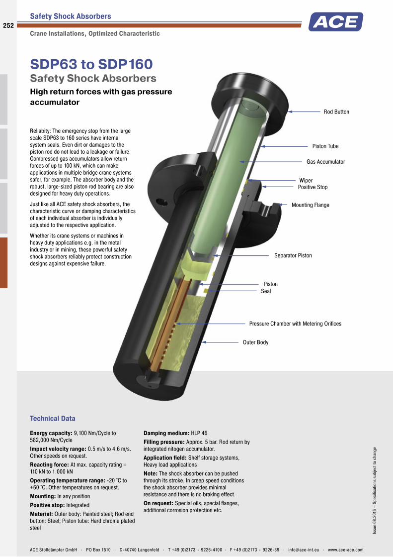
Piston Tube
WiperPositive Stop
Gas Accumulator
Rod Button
SealPiston
Mounting Flange
Outer Body
Separator Piston
Pressure Chamber with Metering Orifices
Technical Data
Reliabity: The emergency stop from the large scale SDP63 to 160 series have internal system seals. Even dirt or damages to the piston rod do not lead to a leakage or failure. Compressed gas accumulators allow return forces of up to 100 kN, which can make applications in multiple bridge crane systems safer, for example. The absorber body and the robust, large-sized piston rod bearing are also designed for heavy duty operations.
Just like all ACE safety shock absorbers, the characteristic curve or damping characteristics of each individual absorber is individually adjusted to the respective application.
Whether its crane systems or machines in heavy duty applications e.g. in the metal industry or in mining, these powerful safety shock absorbers reliably protect construction designs against expensive failure.
SDP63 to SDP160Safety Shock Absorbers High return forces with gas pressure accumulator
Safety Shock Absorbers
Crane Installations, Optimized Characteristic
Energy capacity: 9,100 Nm/Cycle to 582,000 Nm/CycleImpact velocity range: 0.5 m/s to 4.6 m/s. Other speeds on request.Reacting force: At max. capacity rating = 110 kN to 1.000 kNOperating temperature range: -20 °C to +60 °C. Other temperatures on request.Mounting: In any positionPositive stop: IntegratedMaterial: Outer body: Painted steel; Rod end button: Steel; Piston tube: Hard chrome plated steel
Damping medium: HLP 46Filling pressure: Approx. 5 bar. Rod return by integrated nitogen accumulator.Application fi eld: Shelf storage systems, Heavy load applicationsNote: The shock absorber can be pushed through its stroke. In creep speed conditions the shock absorber provides minimal resistance and there is no braking effect.On request: Special oils, special fl anges, additional corrosion protection etc.
252
Issu
e 08
.201
6 –
Spec
ifi ca
tions
sub
ject
to c
hang
e
ACE Stoßdämpfer GmbH . PO Box 1510 . D-40740 Langenfeld . T +49 (0)2173 - 9226-4100 . F +49 (0)2173 - 9226-89 . [email protected] . www.ace-ace.com
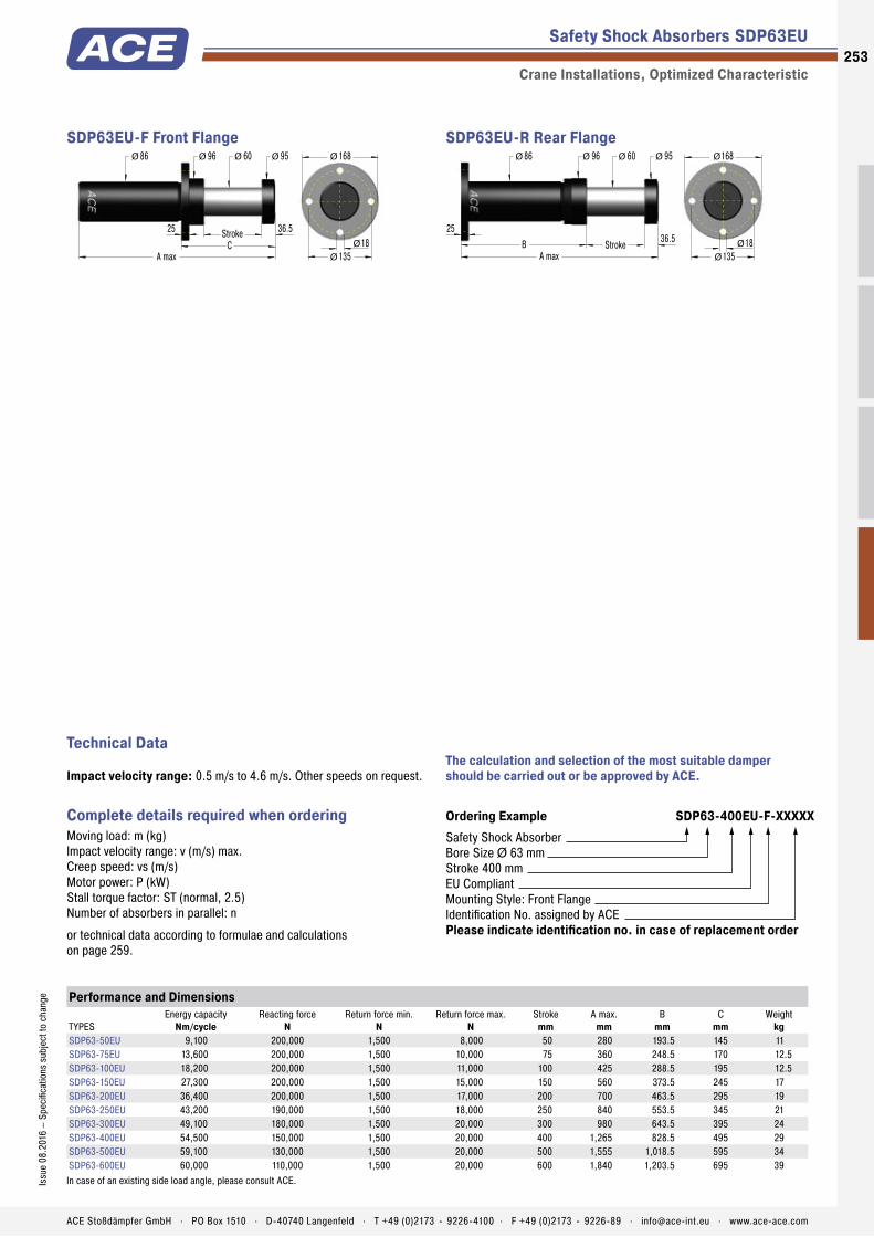
Piston Tube
WiperPositive Stop
Gas Accumulator
Rod Button
SealPiston
Mounting Flange
Outer Body
Separator Piston
Pressure Chamber with Metering Orifices
Performance and Dimensions
TYPESEnergy capacity
Nm/cycleReacting force
NReturn force min.
NReturn force max.
NStroke
mmA max.
mmB
mmC
mmWeight
kgSDP63-50EU 9,100 200,000 1,500 8,000 50 280 193.5 145 11SDP63-75EU 13,600 200,000 1,500 10,000 75 360 248.5 170 12.5SDP63-100EU 18,200 200,000 1,500 11,000 100 425 288.5 195 12.5SDP63-150EU 27,300 200,000 1,500 15,000 150 560 373.5 245 17SDP63-200EU 36,400 200,000 1,500 17,000 200 700 463.5 295 19SDP63-250EU 43,200 190,000 1,500 18,000 250 840 553.5 345 21SDP63-300EU 49,100 180,000 1,500 20,000 300 980 643.5 395 24SDP63-400EU 54,500 150,000 1,500 20,000 400 1,265 828.5 495 29SDP63-500EU 59,100 130,000 1,500 20,000 500 1,555 1,018.5 595 34SDP63-600EU 60,000 110,000 1,500 20,000 600 1,840 1,203.5 695 39In case of an existing side load angle, please consult ACE.
Safety Shock Absorbers SDP63EU
Crane Installations, Optimized Characteristic
Ordering Example SDP63-400EU-F-XXXXXSafety Shock AbsorberBore Size Ø 63 mmStroke 400 mmEU CompliantMounting Style: Front FlangeIdentification No. assigned by ACEPlease indicate identification no. in case of replacement order
Complete details required when ordering Moving load: m (kg)Impact velocity range: v (m/s) max.Creep speed: vs (m/s)Motor power: P (kW)Stall torque factor: ST (normal, 2.5)Number of absorbers in parallel: n
or technical data according to formulae and calculations on page 259.
The calculation and selection of the most suitable damper should be carried out or be approved by ACE.
Technical Data
Impact velocity range: 0.5 m/s to 4.6 m/s. Other speeds on request.
60
A max
36.5
86 96 95
StrokeC
25
Ø Ø Ø Ø 168
13518Ø
Ø
Ø
SDP63EU-F Front Flange
A max
StrokeB
168
135Ø
Ø
18Ø
86Ø 96Ø 60Ø 95Ø
36.525
SDP63EU-R Rear Flange
253Is
sue
08.2
016
– Sp
ecifi
catio
ns s
ubje
ct to
cha
nge
ACE Stoßdämpfer GmbH . PO Box 1510 . D-40740 Langenfeld . T +49 (0)2173 - 9226-4100 . F +49 (0)2173 - 9226-89 . [email protected] . www.ace-ace.com
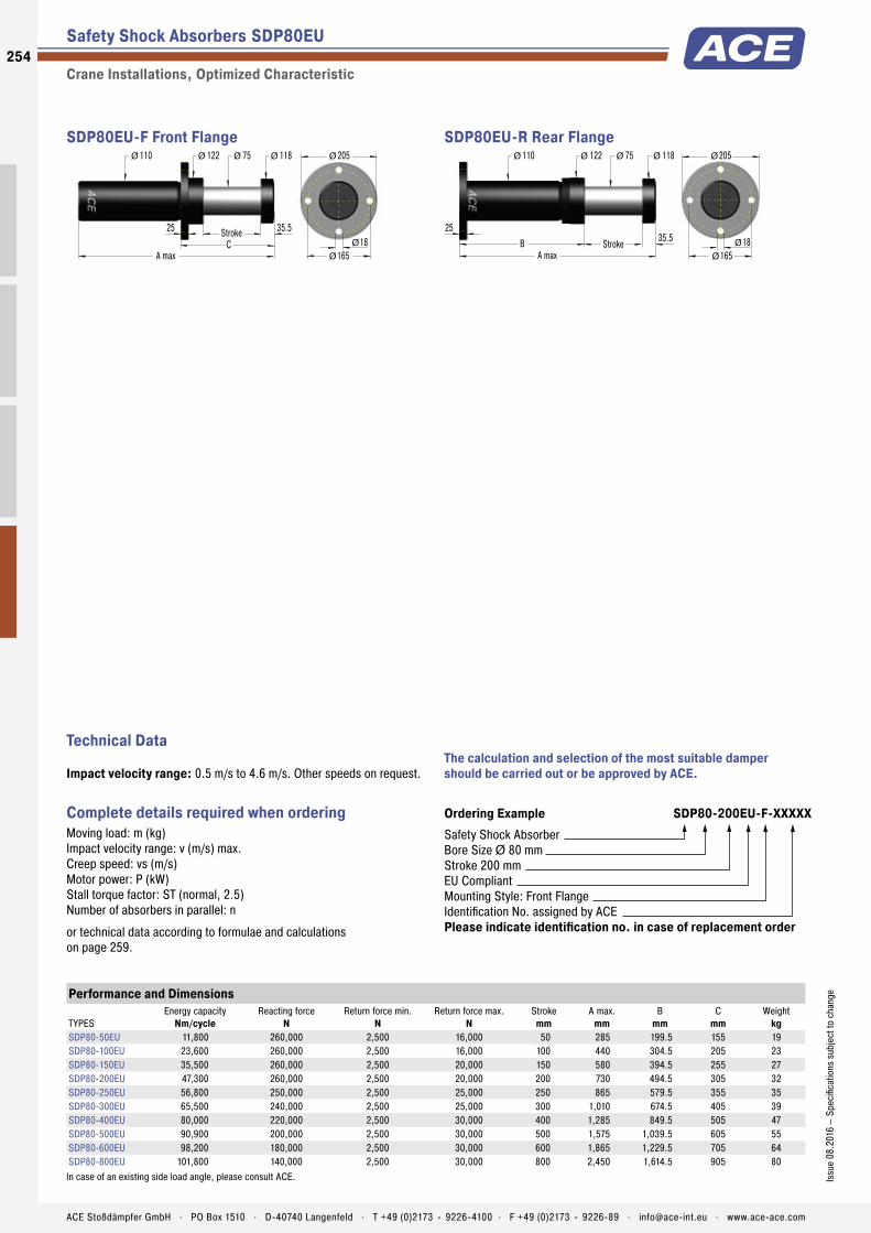
Performance and Dimensions
TYPESEnergy capacity
Nm/cycleReacting force
NReturn force min.
NReturn force max.
NStroke
mmA max.
mmB
mmC
mmWeight
kgSDP80-50EU 11,800 260,000 2,500 16,000 50 285 199.5 155 19SDP80-100EU 23,600 260,000 2,500 16,000 100 440 304.5 205 23SDP80-150EU 35,500 260,000 2,500 20,000 150 580 394.5 255 27SDP80-200EU 47,300 260,000 2,500 20,000 200 730 494.5 305 32SDP80-250EU 56,800 250,000 2,500 25,000 250 865 579.5 355 35SDP80-300EU 65,500 240,000 2,500 25,000 300 1,010 674.5 405 39SDP80-400EU 80,000 220,000 2,500 30,000 400 1,285 849.5 505 47SDP80-500EU 90,900 200,000 2,500 30,000 500 1,575 1,039.5 605 55SDP80-600EU 98,200 180,000 2,500 30,000 600 1,865 1,229.5 705 64SDP80-800EU 101,800 140,000 2,500 30,000 800 2,450 1,614.5 905 80In case of an existing side load angle, please consult ACE.
Safety Shock Absorbers SDP80EU
Crane Installations, Optimized Characteristic
Ordering Example SDP80-200EU-F-XXXXXSafety Shock AbsorberBore Size Ø 80 mmStroke 200 mmEU CompliantMounting Style: Front FlangeIdentification No. assigned by ACEPlease indicate identification no. in case of replacement order
Complete details required when ordering Moving load: m (kg)Impact velocity range: v (m/s) max.Creep speed: vs (m/s)Motor power: P (kW)Stall torque factor: ST (normal, 2.5)Number of absorbers in parallel: n
or technical data according to formulae and calculations on page 259.
The calculation and selection of the most suitable damper should be carried out or be approved by ACE.
Technical Data
Impact velocity range: 0.5 m/s to 4.6 m/s. Other speeds on request.
75
A max
35.5
110 122 118
StrokeC
25
Ø Ø Ø Ø 205
16518Ø
Ø
Ø
SDP80EU-F Front Flange
A max
StrokeB
205
165Ø
Ø
18Ø
110Ø 122Ø 75Ø 118Ø
35.525
SDP80EU-R Rear Flange
254
Issu
e 08
.201
6 –
Spec
ifica
tions
sub
ject
to c
hang
e
ACE Stoßdämpfer GmbH . PO Box 1510 . D-40740 Langenfeld . T +49 (0)2173 - 9226-4100 . F +49 (0)2173 - 9226-89 . [email protected] . www.ace-ace.com

Performance and Dimensions
TYPESEnergy capacity
Nm/cycleReacting force
NReturn force min.
NReturn force max.
NStroke
mmA max.
mmB
mmC
mmWeight
kgSDP100-100EU 47,000 520,000 3,900 38,000 100 460 316.5 230 38SDP100-200EU 95,000 520,000 3,900 38,000 200 750 506.5 330 53SDP100-250EU 114,000 520,000 3,900 40,000 250 890 596.5 380 59SDP100-300EU 131,000 500,000 3,900 40,000 300 1,035 691.5 430 66SDP100-400EU 160,000 480,000 3,900 40,000 400 1,325 881.5 530 81SDP100-500EU 182,000 440,000 3,900 40,000 500 1,610 1,066.5 630 93SDP100-600EU 196,000 360,000 3,900 46,000 600 1,880 1,236.5 730 103SDP100-800EU 218,000 300,000 3,900 46,000 800 2,450 1,606.5 930 125SDP100-1000EU 236,000 260,000 3,900 46,000 1,000 3,020 1,976.5 1,130 160In case of an existing side load angle, please consult ACE.
Safety Shock Absorbers SDP100EU
Crane Installations, Optimized Characteristic
Ordering Example SDP100-400EU-F-XXXXXSafety Shock AbsorberBore Size Ø 100 mmStroke 400 mmEU CompliantMounting Style: Front FlangeIdentification No. assigned by ACEPlease indicate identification no. in case of replacement order
Complete details required when ordering Moving load: m (kg)Impact velocity range: v (m/s) max.Creep speed: vs (m/s)Motor power: P (kW)Stall torque factor: ST (normal, 2.5)Number of absorbers in parallel: n
or technical data according to formulae and calculations on page 259.
The calculation and selection of the most suitable damper should be carried out or be approved by ACE.
Technical Data
Impact velocity range: 0.5 m/s to 4.6 m/s. Other speeds on request.
95
A max
43.5
136 148 138
StrokeC
30
Ø Ø Ø Ø 255
21023Ø
Ø
Ø
SDP100EU-F Front Flange
A max
StrokeB
255
210Ø
Ø
23Ø
136Ø 148Ø 95Ø 138Ø
43.530
SDP100EU-R Rear Flange
255Is
sue
08.2
016
– Sp
ecifi
catio
ns s
ubje
ct to
cha
nge
ACE Stoßdämpfer GmbH . PO Box 1510 . D-40740 Langenfeld . T +49 (0)2173 - 9226-4100 . F +49 (0)2173 - 9226-89 . [email protected] . www.ace-ace.com

Performance and Dimensions
TYPESEnergy capacity
Nm/cycleReacting force
NReturn force min.
NReturn force max.
NStroke
mmA max.
mmB
mmC
mmWeight
kgSDP120-100EU 64,000 700,000 5,600 35,000 100 460 315.5 249 58SDP120-200EU 127,000 700,000 5,600 70,000 200 750 505.5 355 72SDP120-400EU 236,000 650,000 5,600 75,000 400 1,325 880.5 555 99SDP120-600EU 300,000 550,000 5,600 75,000 600 1,880 1,235.5 755 125SDP120-800EU 327,000 450,000 5,600 75,000 800 2,450 1,605.5 955 160SDP120-1000EU 364,000 400,000 5,600 75,000 1,000 3,020 1,975.5 1,155 192SDP120-1200EU 436,000 400,000 5,600 75,000 1,200 3,590 2,345.5 1,355 225In case of an existing side load angle, please consult ACE.
Safety Shock Absorbers SDP120EU
Crane Installations, Optimized Characteristic
Ordering Example SDP120-800EU-F-XXXXXSafety Shock AbsorberBore Size Ø 120 mmStroke 800 mmEU CompliantMounting Style: Front FlangeIdentification No. assigned by ACEPlease indicate identification no. in case of replacement order
Complete details required when ordering Moving load: m (kg)Impact velocity range: v (m/s) max.Creep speed: vs (m/s)Motor power: P (kW)Stall torque factor: ST (normal, 2.5)Number of absorbers in parallel: n
or technical data according to formulae and calculations on page 259.
The calculation and selection of the most suitable damper should be carried out or be approved by ACE.
Technical Data
Impact velocity range: 0.5 m/s to 4.6 m/s. Other speeds on request.
115
A max
44.5
156 185 177
StrokeC
35
Ø Ø Ø Ø 300
24527Ø
Ø
Ø
SDP120EU-F Front Flange
A max
StrokeB
300
245Ø
Ø
27Ø
156Ø 185Ø 115Ø 177Ø
44.535
SDP120EU-R Rear Flange
256
Issu
e 08
.201
6 –
Spec
ifica
tions
sub
ject
to c
hang
e
ACE Stoßdämpfer GmbH . PO Box 1510 . D-40740 Langenfeld . T +49 (0)2173 - 9226-4100 . F +49 (0)2173 - 9226-89 . [email protected] . www.ace-ace.com

Performance and Dimensions
TYPESEnergy capacity
Nm/cycleReacting force
NReturn force min.
NReturn force max.
NStroke
mmA max.
mmB
mmC
mmWeight
kgSDP160-200EU 182,000 1,000,000 1,000 80,000 200 860 596 440 105SDP160-400EU 345,000 950,000 1,000 80,000 400 1,485 1,021 640 165SDP160-500EU 409,000 900,000 1,000 90,000 500 1,765 1,201 740 195SDP160-600EU 469,000 860,000 1,000 95,000 600 2,065 1,401 840 230SDP160-800EU 545,000 750,000 1,000 100,000 800 2,660 1,796 1,040 290SDP160-1000EU 545,000 600,000 1,000 110,000 1,000 3,225 2,161 1,240 350SDP160-1200EU 545,000 500,000 1,000 110,000 1,200 3,815 2,551 1,440 410SDP160-1600EU 582,000 400,000 1,000 110,000 1,600 4,995 3,331 1,840 530In case of an existing side load angle, please consult ACE.
Safety Shock Absorbers SDP160EU
Crane Installations, Optimized Characteristic
Ordering Example SDP160-400EU-F-XXXXXSafety Shock AbsorberBore Size Ø 160 mmStroke 400 mmEU CompliantMounting Style: Front FlangeIdentification No. assigned by ACEPlease indicate identification no. in case of replacement order
Complete details required when ordering Moving load: m (kg)Impact velocity range: v (m/s) max.Creep speed: vs (m/s)Motor power: P (kW)Stall torque factor: ST (normal, 2.5)Number of absorbers in parallel: n
or technical data according to formulae and calculations on page 259.
The calculation and selection of the most suitable damper should be carried out or be approved by ACE.
Technical Data
Impact velocity range: 0.5 m/s to 4.6 m/s. Other speeds on request.
150
A max
64
206 230 185
StrokeC
50
Ø Ø Ø Ø 350
29527Ø
Ø
Ø
6x60°
SDP160EU-F Front Flange
A max
StrokeB
350
29527Ø
Ø
Ø 206Ø 230Ø 150Ø 185Ø
5064
6x60°
SDP160EU-R Rear Flange
257Is
sue
08.2
016
– Sp
ecifi
catio
ns s
ubje
ct to
cha
nge
ACE Stoßdämpfer GmbH . PO Box 1510 . D-40740 Langenfeld . T +49 (0)2173 - 9226-4100 . F +49 (0)2173 - 9226-89 . [email protected] . www.ace-ace.com

Permitted UseACE safety shock absorbers are machine elements to brake moving masses in a defined end position in emergency stop situations for axial forces. The safety shock absorbers are not designed for regular operational usage.
Calculation of safety shock absorbersThe calculation of safety shock absorbers should generally be perfor-med or checked by ACE.
Deceleration PropertiesThe orifice sizing and drill pattern in the pressure chamber are individu-ally designed for each safety shock absorber. The respective absorption characteristic is optimised corresponding to the maximum mass that occurs in the emergency stop and the impact speed. Correspondingly, each safety shock absorber is given an individual identification number.
Model CodeFor types SCS33 to 64, the individual five-digit identification numbers can be taken from the last digits of the shock absorber model code shown on the label. Example: SCS33-50EU-1XXXX. For type series SDH38 to SDH63 and SDP63 to SDP160, the identification number is a five digit number. Example: SDH38-400EU-F-XXXXX. In addition to the model code, the label also shows the authorised maximum impact velocity and maximum authorised impact mass for the unit.
MountingTo mount the shock absorber, we recommend the use of original ACE mounting accessories shown in catalogue.The mounting of each shock absorber must be exactly positioned so that the reaction force (Q) can be adequately transmitted into the mounting structure.ACE recommends installation via the front flange -F mounting style that ensures the maximum protection against buckling. The damper must be mounted so that the moving loads are decelerated with the least possible side loading to the piston rod. The maximum permissable side load angles are detailed in our current catalogue.The entire stroke length must be used for deceleration because only using part of the stroke can lead to overstressing and damage to the unit.
Mounting style front flange
Safety Shock Absorber SDH Safety Shock Absorber SDP
Environmental RequirementsThe permissible temperature range for each shock absorber type can be found in our current catalogue. Caution: Usage outside the specified temperature range can lead to premature breakdown and damage of of the shock absorbers which can then result in severe system damage or machine failures.Trouble free operation outdoors or in damp environments is only war- ranted if the dampers are coated with a specific corrosion protection finish.
Initial Start-Up ChecksFirst impacts on the shock absorber should only be tried after correctly mounting and with reduced impact speeds and – if possible – with reduced load. Differences between calculated and actual operating data can then be detected early on, and damage to your system can be avoided. If the shock absorbers were selected on calculated data that does not correspond to the maximum possible loading (i.e. selection based on drive power being switched off or at reduced impact speed) then these restricted impact conditions must not be exceeded during initial testing or subsequent use of the system. Otherwise you risk damaging the shock absorbers and/or your machine by overstressing materials. After the initial trial check that the piston rod fully extends again and that there are no signs of oil leakage. Also check that the mounting hardware is still securely tightened. You need to satisfy your- self that no damage has occurred to the piston rod, the body, or the mounting hardware.
Fixed Mechanical StopSafety shock absorbers do not need an external stop as a stroke limiter. The stroke of the safety absorber is limited by the stop of the impact head on the shock absorber. For types SCS33 to SCS64, the fixed stop point is achieved with the integrated stop collar.
What Needs to be Checked after a Full Load Impact?Safety shock absorbers that were originally checked only at reduced speed or load need to be checked again after a full load impact (i.e. emergency use) has occurred. Check that the piston rod fully extends to its full out position, that there are no signs of oil leakage and that the mounting hardware is still securely fixed. You need to satisfy yourself that no damage has occurred to the piston rod, the body, or the mount- ing hardware. If no damage has occurred, the safety shock absorber can be put back into normal operation (see initial start-up).
MaintenanceSafety shock absorbers are sealed systems and do not need special maintenance. Safety shock absorbers that are not used regularly (i.e. that are intended for emergency stop systems) should be checked within the normal time frame for safety checks, but at least once a year. At this time special attention must be paid to checking that the piston rod resets to its fully extended position, that there is no oil leakage and that the mounting brackets are still secure and undamaged. The piston rod must not show any signs of damage. Safety shock absorbers that are in use regularly should be checked every three months.
Repair NoticeIf any damage to the shock absorber is detected or if there are any doubts as to the proper functioning of the unit please send the unit for service to ACE. Alternatively contact your local ACE office for further advice.
Detailed information on the above listed points can be taken from the corresponding operating and assembly instructions.
Safety Shock Absorbers
General Instructions258
Issu
e 08
.201
6 –
Spec
ifica
tions
sub
ject
to c
hang
e
ACE Stoßdämpfer GmbH . PO Box 1510 . D-40740 Langenfeld . T +49 (0)2173 - 9226-4100 . F +49 (0)2173 - 9226-89 . [email protected] . www.ace-ace.com

Formulae and Calculations
Safety Shock Absorbers
Calculation Bases for the Design of Safety Shock Absorbers
Key to symbols usedW1 Kinetic energy per cycle NmW2 Propelling force energy per cycle NmW3 Total energy per cycle (W1 + W2) Nm1 W4 Total energy per hour (W3 · x) Nm/hrme Effective weight kgm Mass to be decelerated kgn Number of shock absorbers (in parallel)2 v Velocity at impact m/s
1 All mentioned values of W4 in the capacity charts are only valid for room temperature. There are reduced values at higher temperature ranges.2 v or vD is the fi nal impact velocity of the mass. With accelerating motion the fi nal impact velocity can be 1.5 to 2 times higher than the average. Please take this into account
when calculating kinetic energy.
In all the following examples the choice of shock absorbers made from the capacity chart is based upon the values of (W3), (W4), (me) and the desired shock absorber stroke (s).
Application Formulae Example
19 Wagon against 2 shock absorbers W1 = m · v2 · 0.25W2 = F · sW3 = W1 + W2vD = v · 0.5
m = 5000 kgv = 2 m/sF = 3500 Ns = 0.10 m (chosen)
W1 = 5000 · 22 · 0.25 = 5000 NmW2 = 3500 · 0.10 = 350 NmW3 = 5000 + 350 = 5350 NmvD = 2 · 0.5 = 1 m/sChosen from capacity chart:Model SDH38-100EU self-compensating
s
F
s
m1
20 Wagon against wagon W1 = m1· m2 · (v1+v2)2 · 0.5
(m1+m2)W2 = F · sW3 = W1 + W2vD = v1 + v2
m = 7000 kgv1 = 1.2 m/sm2 = 10000 kgv2 = 0.5 m/sF = 5000 Ns = 0.10 m (chosen)
W1 = 7000 · 10000 · 1.72 · 0.5 = 5950 Nm (7000+10000)W2 = 5000 · 0.10 = 500 NmW3 = 5950 + 500 = 6450 NmvD = 1.2 + 0.5 = 1.7 m/sChosen from capacity chart:Model SDH50-100EU self-compensating
s
F2m2F1 m1
21 Wagon against wagon 2 shock absorbers
W1 = m1· m2 · (v1+v2)2 · 0.25
(m1+m2)W2 = F · sW3 = W1 + W2
vD = v1 + v2 2
m = 7000 kgv1 = 1.2 m/sm2 = 10000 kgv2 = 0.5 m/sF = 5000 Ns = 0.10 m (chosen)
W1 = 7000 · 10000 · 1.72 · 0.25 = 2 975 Nm (7000+10000)W2 = 5000 · 0.10 = 500 NmW3 = 2975 + 510 = 3475 NmvD = (1.2 + 0.5) : 2 = 0.85 m/sChosen from capacity chart:Model SDH38-100EU self-compensating
s
m1
F1
s
m2
F2
2 vD Impact velocity at shock absorber m/sF Propelling force Nc Cycles per hour 1/hr s Shock absorber stroke mQ Reaction force Nt Deceleration time sa Deceleration m/s2
Note: When using several shock absorbers in parallel, the values (W3), (W4) and (me) are divided according to the number of units used.
ACE shock absorbers provide linear deceleration and are therefore superior to other kinds of damping element. It is easy to calculate around 90 % of applications knowing only the following four parameters:
1. Mass to be decelerated (weight) m [kg]2. Impact velocity at shock absorber vD [m/s]3. Propelling force F [N]4. Number of absorbers in parallel n
More formulae on page 10 to 13
259Is
sue
08.2
016
– Sp
ecifi
catio
ns s
ubje
ct to
cha
nge
ACE Stoßdämpfer GmbH . PO Box 1510 . D-40740 Langenfeld . T +49 (0)2173 - 9226-4100 . F +49 (0)2173 - 9226-89 . [email protected] . www.ace-ace.com

Application Examples
Safety Shock Absorbers
SCS45EU
Controlled emergency stopACE safety shock absorbers protect precision assembly jigs for the aircraft industry. The basic mount of this coordinate measuring machine for the production of parts in the aircraft industry is made of granite and must not be damaged. To avoid damage from operating errors or mishandling, all movement axes were equipped with safety shock absorbers of the type SCS45-50EU. If the turntables malfunction the safety shock absorbers decelerate the loads before expensive damage can occur to the granite measuring tables.
s
m
Optimally protected turntable
SCS33EU, SCS45EU
High-level protection of linear modulesSafety shock absorbers produced by ACE are installed in the top linear system models of one of the most prestigious companies in the fi eld of drive and control technology. Their job: to protect the z-axis from damage caused by uncontrolled movements. Various safety dampers are used for different load ranges. Tests have shown that, in the worst case, a collision speed of up to 5 m/s might occur. To be on the safe side, the interpretations were based in all cases on a slightly higher value.
s
mF
For protecting equipment and modules such as these, the SCS series from ACE is the ideal solution in the emergency stop sector Roth GmbH & Co. KG, 90411 Nürnberg, Germany and Bosch Rexroth AG, 97816 Lohr am Main, Germany
260
Issu
e 08
.201
6 –
Spec
ifi ca
tions
sub
ject
to c
hang
e
ACE Stoßdämpfer GmbH . PO Box 1510 . D-40740 Langenfeld . T +49 (0)2173 - 9226-4100 . F +49 (0)2173 - 9226-89 . [email protected] . www.ace-ace.com
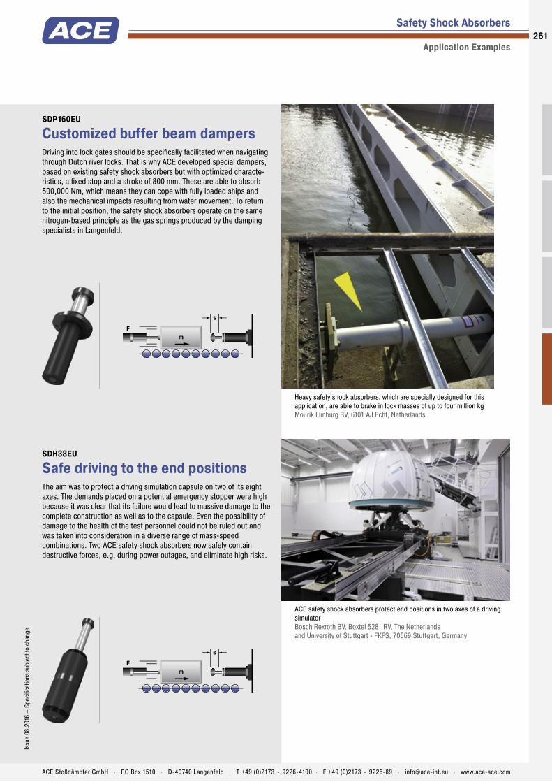
Safety Shock Absorbers
Application Examples
SDP160EU
Customized buffer beam dampersDriving into lock gates should be specifi cally facilitated when navigating through Dutch river locks. That is why ACE developed special dampers, based on existing safety shock absorbers but with optimized characte-ristics, a fi xed stop and a stroke of 800 mm. These are able to absorb 500,000 Nm, which means they can cope with fully loaded ships and also the mechanical impacts resulting from water movement. To return to the initial position, the safety shock absorbers operate on the same nitrogen-based principle as the gas springs produced by the damping specialists in Langenfeld.
s
mF
Heavy safety shock absorbers, which are specially designed for this application, are able to brake in lock masses of up to four million kg Mourik Limburg BV, 6101 AJ Echt, Netherlands
SDH38EU
Safe driving to the end positionsThe aim was to protect a driving simulation capsule on two of its eight axes. The demands placed on a potential emergency stopper were high because it was clear that its failure would lead to massive damage to the complete construction as well as to the capsule. Even the possibility of damage to the health of the test personnel could not be ruled out and was taken into consideration in a diverse range of mass-speed combinations. Two ACE safety shock absorbers now safely contain destructive forces, e.g. during power outages, and eliminate high risks.
s
mF
ACE safety shock absorbers protect end positions in two axes of a driving simulator Bosch Rexroth BV, Boxtel 5281 RV, The Netherlands and University of Stuttgart - FKFS, 70569 Stuttgart, Germany
261Is
sue
08.2
016
– Sp
ecifi
catio
ns s
ubje
ct to
cha
nge
ACE Stoßdämpfer GmbH . PO Box 1510 . D-40740 Langenfeld . T +49 (0)2173 - 9226-4100 . F +49 (0)2173 - 9226-89 . [email protected] . www.ace-ace.com
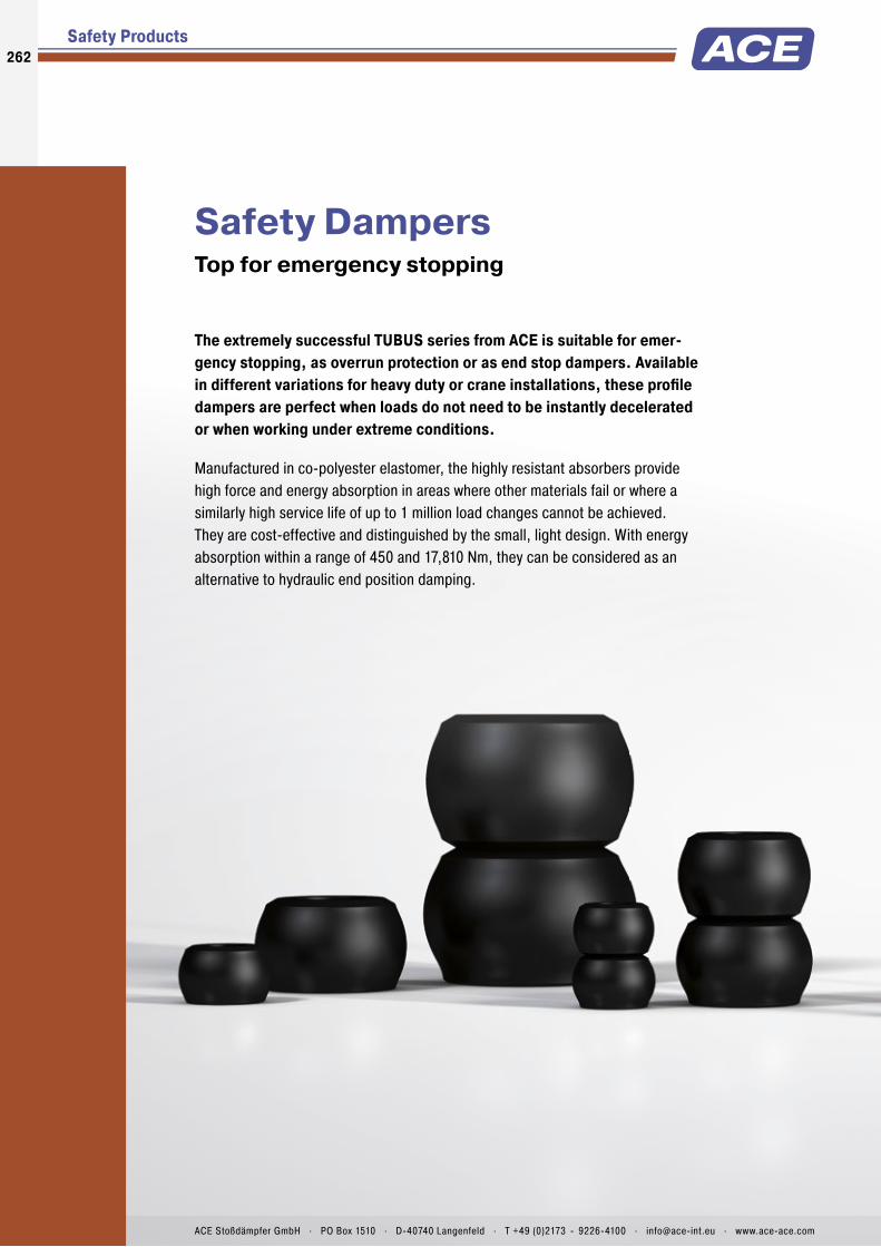
Safety Products
Safety DampersTop for emergency stopping
The extremely successful TUBUS series from ACE is suitable for emer-gency stopping, as overrun protection or as end stop dampers. Available in different variations for heavy duty or crane installations, these profi le dampers are perfect when loads do not need to be instantly decelerated or when working under extreme conditions.
Manufactured in co-polyester elastomer, the highly resistant absorbers provide high force and energy absorption in areas where other materials fail or where a similarly high service life of up to 1 million load changes cannot be achieved. They are cost-effective and distinguished by the small, light design. With energy absorption within a range of 450 and 17,810 Nm, they can be considered as an alternative to hydraulic end position damping.
262262
ACE Stoßdämpfer GmbH . PO Box 1510 . D-40740 Langenfeld . T +49 (0)2173 - 9226-4100 . [email protected] . www.ace-ace.com

Product Families
Overview
Safety Dampers
TUBUS TC and TC-S Crane Installations Compact powerhouseCrane systems, Loading and lifting equipment, Hydraulic devices, Electro-mechanical drives
Page 264
TUBUS TI Irreversible Emergency Stop Damper Compact one-off decelerationEmergency stop damping in linear axes, Portal systems, Test stations, Electro-mechanical drives
Page 266
Extremely durable
Highly resistant co-polyester elastomers
Lightweight designs
Cost-effective use
Heavy-duty versions available
263
ACE Stoßdämpfer GmbH . PO Box 1510 . D-40740 Langenfeld . T +49 (0)2173 - 9226-4100 . F +49 (0)2173 - 9226-89 . [email protected] . www.ace-ace.com

Profile Body
Mounting Screw
Technical Data
For even more protection: The profi le dampers from the TC range of the ACE TUBUS-Series can also be used as safety dampers. These maintenance-free, ready-to-install damping elements made of co-polyester elastomer have been specially developed for use in crane systems and fulfi l the international industry standards OSHA and CMAA. In the special TC-S design, managed to achieve the spring rate required for crane systems with the unique dual concept.
Whether TC-S or TC, this range of models represents a cost-effective solution with high energy absorption for energy management systems. The very small and light design of Ø 64 mm to Ø 176 mm progressively covers energy absorption within a range of 450 Nm to 17,810 Nm.
The profi le dampers from the TC range protect cranes, loading and lifting equipment, hydraulic units and much more.
TUBUS TC and TC-SSafety Dampers Compact powerhouse
Safety Dampers
Crane Installations
Energy capacity: 630 Nm/Cycle to 17,810 Nm/CycleEnergy absorption: 31 % to 64 %Dynamic force range: 80,000 N to 978,000 NOperating temperature range: -40 °C to +90 °CConstruction size: 64 mm to 176 mmMaterial hardness rating: Shore 55DMaterial: Profi le body: Co-Polyester ElastomerMounting: In any position
Environment: Resistant to microbes, seawater or chemical attack. Excellent UV and ozone resistance. Material does not absorb water or swell.Impact velocity range: Max. 5 m/sTorque max.: M12: 50 Nm M16: 40 Nm (DIN912) M16: 120 Nm (shouldered screw)Application fi eld: Crane systems, Loading and lifting equipment, Hydraulic devices, Electro-mechanical drivesNote: Suitable for emergency stop applica-tions and for continous use. For applications
with preloading and increased temperatures please consult ACE.On request: Special strokes, -characteristics, -spring rates, -sizes and -materials.
264
Issu
e 08
.201
6 –
Spec
ifi ca
tions
sub
ject
to c
hang
e
ACE Stoßdämpfer GmbH . PO Box 1510 . D-40740 Langenfeld . T +49 (0)2173 - 9226-4100 . F +49 (0)2173 - 9226-89 . [email protected] . www.ace-ace.com

Profile Body
Mounting Screw
Safety Dampers TC
Crane Installations
Stroke (mm)
Ener
gy (N
m)
1800
1500
1200
900
600
300
0 10 15 20 25 30 35 40
450
400
350
300
250
200
150
100
50
0 10 15 20 25 30 35 40
Stroke (mm)
Forc
e (k
N)
absorbed energy
rebound stroke energy
F in
F back
Characteristics
Ordering Example TC83-73-STUBUS Crane BufferOuter-Ø 83 mmStroke 73 mmModel Type Soft
The calculation and selection of the most suitable damper should be carried out or be approved by ACE.
With the aid of the characteristic curves above you can estimate the proportion of the total energy that will be absorbed.Example: With impact energy of 1,300 Nm the Energy-Stroke diagram shows that a stroke of about 38 mm is needed.On the Force-Stroke diagram you can estimate the proportion of absorbed energy to rebound energy at this stroke length.Note: With these types the return force towards the end of the stroke is signifi cant and we recommend you try to use a minimum of 90 % of the total stroke available.Dynamic (v > 0.5 m/s) and static (v ≤ 0.5 m/s) characteristics of all types are available on request.
Type TC90-49Energy-Stroke Characteristic (dynamic)(with impact velocity over 0.5 m/s)
Type TC90-49Force-Stroke Characteristic (dynamic)(with impact velocity over 0.5 m/s)
Performance and Dimensions
TYPES
1 W3Nm/cycle
Emergency stopW3
Nm/cycleStroke max.
mmA
mmd1
mmd2
mmd3
mmLM
mmM Weight
kgTC64-62-S 450 630 62 79 64 52 89 12 M12 0.175TC74-76-S 980 1,372 76 96 74 61 114 12 M12 0.261TC83-73-S 1,940 2,715 73 94 83 69 127 12 M12 0.328TC86-39 1,210 1,695 39 56 86 78 133 12 M12 0.284TC90-49 1,640 2,295 49 68 90 67 124 12 M12 0.265TC100-59 1,785 2,500 59 84 100 91 149 12 M12 0.513TC102-63 1,970 2,760 63 98 102 82 140 22 M16 0.633TC108-30 1,900 2,660 30 53 108 77 133 12 M12 0.392TC117-97 3,710 5,195 97 129 117 100 188 16 M16 1.053TC134-146-S 7,310 10,230 146 188 134 117 215 30 M16 1.573TC136-65 4,250 5,950 65 106 136 106 178 16 M16 1.173TC137-90 6,350 8,890 90 115 137 113 216 21 M16 1.193TC146-67-S 8,330 11,660 67 118 146 99 191 16 M16 1.573TC150-178-S 8,860 12,400 178 241 150 132 224 16 M16 2.581TC153-178-S 7,260 10,165 178 226 153 131 241 16 M16 2.493TC168-124 10,100 14,140 124 166 168 147 260 16 M16 2.533TC176-198-S 12,725 17,810 198 252 176 150 279 16 M16 3.685
1 Max. energy capacity per cycle for continous use.
d3 d2d1
LM A
Max.Stroke
M
d3 d2d1
LM A
Max.Stroke
M
Model Type TC Model Type TC-S
TC
265Is
sue
08.2
016
– Sp
ecifi
catio
ns s
ubje
ct to
cha
nge
ACE Stoßdämpfer GmbH . PO Box 1510 . D-40740 Langenfeld . T +49 (0)2173 - 9226-4100 . F +49 (0)2173 - 9226-89 . [email protected] . www.ace-ace.com

One-Piece Outer Body with Thread
Metal Guide Sleeve
Technical Data
Once only, but safely: ACE now offers these innovative single use TUBUS TI absorbers for emergency stop applications as an alternative to the successful TUBUS profi le dampers. In comparison to standard elastomer absorbers, these safety dampers ensure energy absorp-tion of up to 96 % without a recoil effect. The dampers are deformed in the impact and cannot be reused afterwards.
The easy to assemble and maintenance-free single hit damper are also a cost-effective alternative to the hydraulic safety shock absorbers from ACE. They are made of a high quality synthetic with an inside metal core and absorb up to 4,510 Nm energy.
The TUBUS TI is mainly used as emergency stop damping in linear axes, tool machines, servo drives with high speeds and other similar areas.
TUBUS TI Safety Dampers Compact one-off deceleration
Safety Dampers
Irreversible Emergency Stop Damper
Energy capacity: 562 Nm/Cycle to 4,510 Nm/CycleEnergy absorption: 91 % to 96 %Dynamic force range: 37,100 N to 121,100 NOperating temperature range: -40 °C to +90 °C, Co-polyester Elastomer-25 °C to +50 °C, PolymerConstruction size: 32 mm to 50 mmMaterial: Profi le body: Co-Polyester elastomer or polymer; Guide sleeve: MetalMounting: In any position
Environment: Resistant to lubricants and chemical attack according to resistance list. No UV resistance.Impact velocity range: Max. 5 m/sTorque max.: Finger tightApplication fi eld: Emergency stop damping in linear axes, Portal systems, Test stations, Electro-mechanical drivesNote: The single-use damper must be replaced after each impact.On request: Other construction sizes on request.
266
Issu
e 08
.201
6 –
Spec
ifi ca
tions
sub
ject
to c
hang
e
ACE Stoßdämpfer GmbH . PO Box 1510 . D-40740 Langenfeld . T +49 (0)2173 - 9226-4100 . F +49 (0)2173 - 9226-89 . [email protected] . www.ace-ace.com
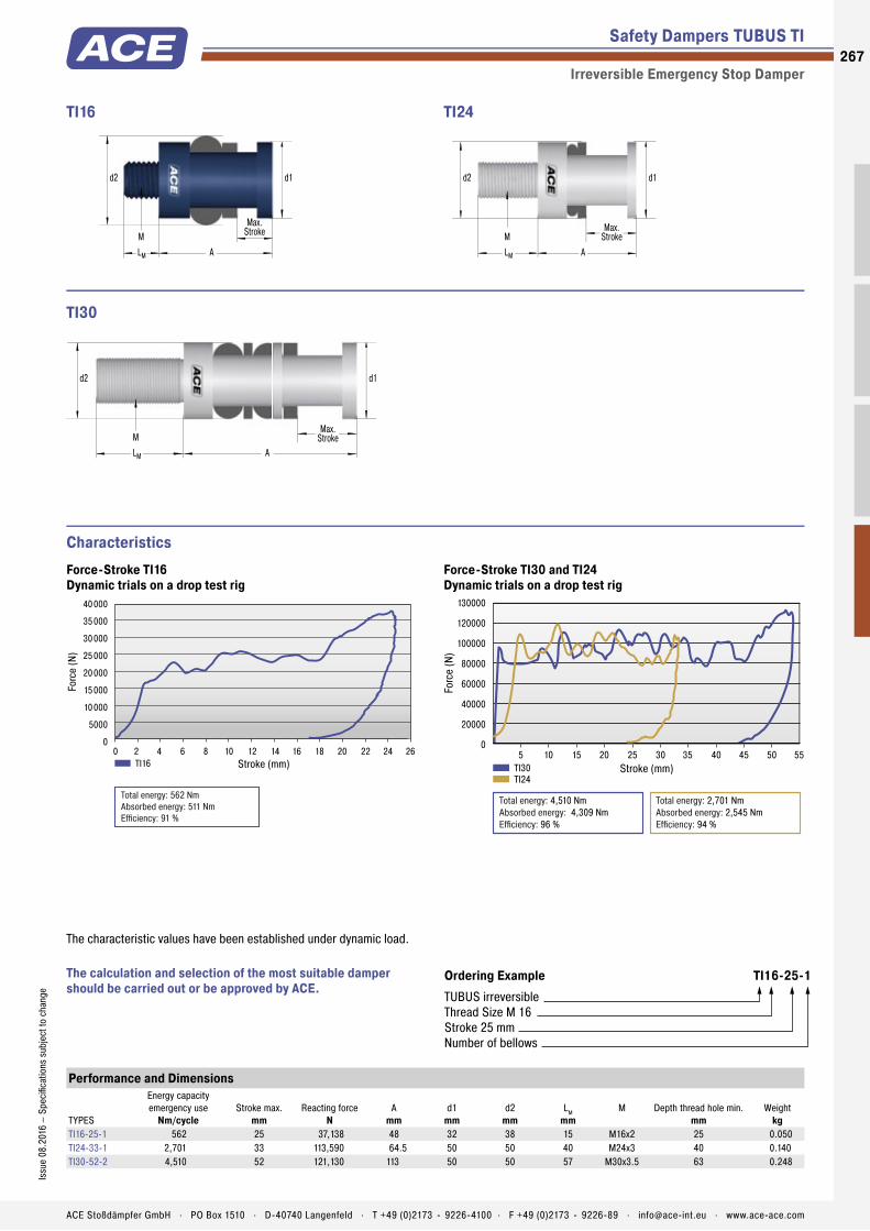
One-Piece Outer Body with Thread
Metal Guide Sleeve
Safety Dampers TUBUS TI
Irreversible Emergency Stop Damper
d2 d1
ALM
MMax.
Stroke
TI16
d2 d1
ALM
MMax.
Stroke
TI24
d2 d1
ALM
MMax.
Stroke
TI30
Performance and Dimensions
TYPES
Energy capacity emergency use
Nm/cycleStroke max.
mmReacting force
NA
mmd1
mmd2
mmLM
mmM Depth thread hole min.
mmWeight
kgTI16-25-1 562 25 37,138 48 32 38 15 M16x2 25 0.050TI24-33-1 2,701 33 113,590 64.5 50 50 40 M24x3 40 0.140TI30-52-2 4,510 52 121,130 113 50 50 57 M30x3.5 63 0.248
Stroke (mm)
Forc
e (N
)
40000
35000
30000
25000
20000
15000
10000
5000
00 2 4 6 8 10 12 14 16 18 20 22 24 26
Total energy: 562 NmAbsorbed energy: 511 NmEfficiency: 91 %
TI16 Stroke (mm)
Forc
e (N
)
130000
120000
100000
80000
60000
40000
20000
0 5 10 15 20 25 30 35 40 45 50 55
TI30TI24
Total energy: 4,510 NmAbsorbed energy: 4,309 NmEfficiency: 96 %
Total energy: 2,701 NmAbsorbed energy: 2,545 NmEfficiency: 94 %
Characteristics
Ordering Example TI16-25-1TUBUS irreversibleThread Size M 16 Stroke 25 mmNumber of bellows
The calculation and selection of the most suitable damper should be carried out or be approved by ACE.
The characteristic values have been established under dynamic load.
Force-Stroke TI16Dynamic trials on a drop test rig
Force-Stroke TI30 and TI24Dynamic trials on a drop test rig
267Is
sue
08.2
016
– Sp
ecifi
catio
ns s
ubje
ct to
cha
nge
ACE Stoßdämpfer GmbH . PO Box 1510 . D-40740 Langenfeld . T +49 (0)2173 - 9226-4100 . F +49 (0)2173 - 9226-89 . [email protected] . www.ace-ace.com

268268
ACE Stoßdämpfer GmbH . PO Box 1510 . D-40740 Langenfeld . T +49 (0)2173 - 9226-4100 . [email protected] . www.ace-ace.comACE Stoßdämpfer GmbH . PO Box 1510 . D-40740 Langenfeld . T +49 (0)2173 - 9226-4100 . [email protected] . www.ace-ace.com
Safety Products
Clamping ElementsOn-the-spot clamping and stopping in emergencies and other situations
Clamping elements from the LOCKED series also serve the purpose of safety. These ACE products clamp and decelerate loads and are suitable for perfectly controlled holding, both linear and rotary, in all processes.
Alongside ACE LOCKED solutions for conventional rail, rod or rotation clamping, special clamps with safety function for Z-axes, which reliably help secure axes with a gravitational load, are available in the LOCKED LZ-P series. The latter solution is available for both pneumatic operation and as an electric version. Whether Z-axes, linear guide, rod or rotation clamping, the choice is (typical of ACE) as large as the performance capacity of the products, which are compatible with the solutions of all standard manufacturers.

ACE Stoßdämpfer GmbH . PO Box 1510 . D-40740 Langenfeld . T +49 (0)2173 - 9226-4100 . F +49 (0)2173 - 9226-89 . [email protected] . www.ace-ace.com
269
ACE Stoßdämpfer GmbH . PO Box 1510 . D-40740 Langenfeld . T +49 (0)2173 - 9226-4100 . F +49 (0)2173 - 9226-89 . [email protected] . www.ace-ace.com
Clamping Elements
Increased process reliability
Available as clamping and emergency stop brakes
Very short stop distances
Very high clamping forces
Compact designs
Ideal for all standard sizes
LOCKED by ACE. After all, safe is safe.

I = J max + 0.01/ + 0.03 (grinding size)
I = J max + 0.01/ + 0.03 (grinding size)
Flat face/mounting surface
J max (manufacturer’s data)
Flat face/mounting surface
J max (manufacturer’s data)
ReleasedThe chamber fi lled with compressed air between the spring steel plates relaxes and thus releases the clamping/brake pads from the rail. The clamping element is now free to move.
Position ClampingThe types of the LOCKED series PL and PLK are designed for clamping directly on the linear guide. The clamping linings are produced from tool steel and offer 100 % clamping force, even in the case of lubricated rails.
EngagedThe clamping force of the mechanically pre-stressed spring steel plates is transferred to the clamping/brake pads as holding force. The clamping element is clamped on the guide rail.
Position Clamping and Emergency Stop BrakingWith the typical SL, SLK, low-wear sinter graphite linings are employed. These enable both a position clamping, as well as emergency stop braking on the linear guide. In case of lubricated rails, a stopping force of 60 % of the nominal stopping force should be considered.
The internal dimension “I” between the linings of every LOCKED rail clamping is ground to an exact value. This is always 0.01 to 0.03 mm greater than the upper limit J max. of the respective linear guide rail (see drawing), resulting from the manufacturer’s directives. The maximum holding force results at J max. and, in the most unfavorable case, holding force losses up to 30 % can occur (see table).
Clamping
Clamping element ventilated
Braking
Clamping element vented
Air Gap Lining/Linear Guide Rail
mm
Loss in Holding Force
%0.01 50.03 100.05 200.07 30
Safe deceleration of a mass that is traversed with the help of a rail and guide rail and track carriage combination must be complied with and not only for safety reasons; reliable clamps in the production processes are also becoming increasingly important.Both features can be taken care of by the clamping elements from ACE. All clamping elements work with the patented spring steel plate system.This system achieves braking and clamping forces of up to 10,000 N. The clamping elements are always individually adapted to the used linear guide. They are available for all rail sizes and profi les for all renowned manufacturers.
Rail Clamping For safe deceleration of rail-guided construction elements
All process and safety clamps work with the reinforced spring steel plate system. Compressed air is introduced between the two spring plates, which are connected with a surrounding rubber coating.If pressure is applied, the clamping element can freely move; if the clamping element is vented clamping to the guide rail follows.
The process clamps and safety clamps are available completely identical in their structure.They differ only in the clamping and brake pads material.
Technical Information – Clamp Versions
Clamping Elements
Function of clamping elements LOCKED PL/SL/PLK/SLK
Slot dimensions between braking and clamping linings and linear guide rail
Different brake pads for PL/PLK and for SL/SLK
270
Issu
e 08
.201
6 –
Spec
ifi ca
tions
sub
ject
to c
hang
e
ACE Stoßdämpfer GmbH . PO Box 1510 . D-40740 Langenfeld . T +49 (0)2173 - 9226-4100 . F +49 (0)2173 - 9226-89 . [email protected] . www.ace-ace.com
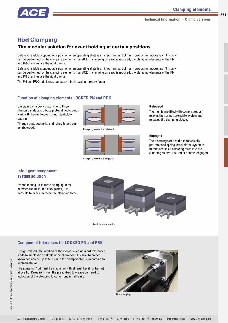
Clamping element is released
Clamping element is engaged
Rod clamping
Clamping Elements
Technical Information – Clamp Versions
ReleasedThe membrane fi lled with compressed air relaxes the spring steel plate system and releases the clamping sleeve.
EngagedThe clamping force of the mechanically pre-stressed spring steel plates system is transferred as as a holding force into the clamping sleeve. The rod or shaft is engaged.
Intelligent component system solution
Safe and reliable stopping at a position or an operating state is an important part of many production processes. This task can be performed by the clamping elements from ACE. If clamping on a rod is required, the clamping elements of the PN and PRK families are the right choice.Safe and reliable stopping at a position or an operating state is an important part of many production processes. This task can be performed by the clamping elements from ACE. If clamping on a rod is required, the clamping elements of the PN and PRK families are the right choice.The PN and PRK rod clamps can absorb both axial and rotary forces.
Rod Clamping The modular solution for exact holding at certain positions
Consisting of a deck plate, one to three clamping units and a base plate, all rod clamps work with the reinforced spring steel plate system. Through that, both axial and rotary forces can be absorbed.
Modular construction
Function of clamping elements LOCKED PN and PRK
Component tolerances for LOCKED PN and PRK
By connecting up to three clamping units between the base and deck plates, it is possible to easily increase the clamping force.
Design-related, the addition of the individual component tolerances leads to an elastic axial tolerance allowance.This axial tolerance allowance can be up to 500 µm in the clamped status, according to implementation!The axis/shaft/rod must be machined with at least h9-fi t (or better) above h5. Deviations from the prescribed tolerance can lead to reduction of the stopping force, or functional failure.
271Is
sue
08.2
016
– Sp
ecifi
catio
ns s
ubje
ct to
cha
nge
ACE Stoßdämpfer GmbH . PO Box 1510 . D-40740 Langenfeld . T +49 (0)2173 - 9226-4100 . F +49 (0)2173 - 9226-89 . [email protected] . www.ace-ace.com
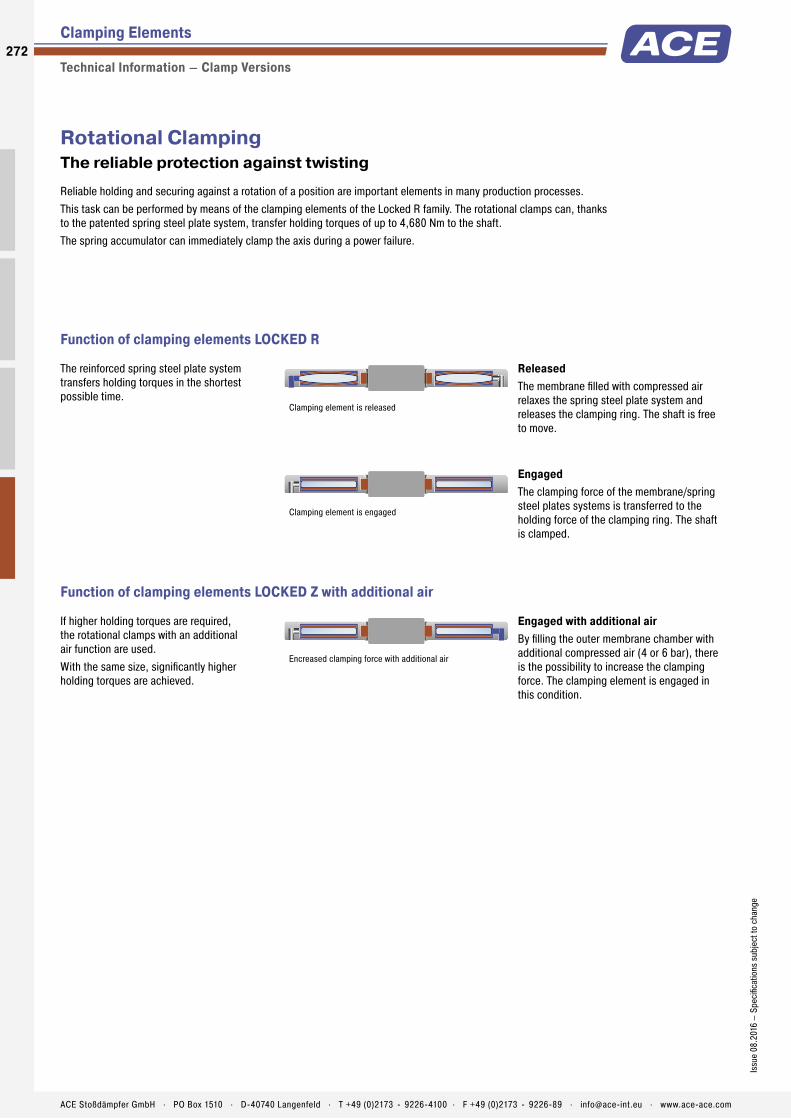
ReleasedThe membrane fi lled with compressed air relaxes the spring steel plate system and releases the clamping ring. The shaft is free to move.
EngagedThe clamping force of the membrane/spring steel plates systems is transferred to the holding force of the clamping ring. The shaft is clamped.
Engaged with additional airBy fi lling the outer membrane chamber with additional compressed air (4 or 6 bar), there is the possibility to increase the clamping force. The clamping element is engaged in this condition.
Encreased clamping force with additional air
Reliable holding and securing against a rotation of a position are important elements in many production processes.This task can be performed by means of the clamping elements of the Locked R family. The rotational clamps can, thanks to the patented spring steel plate system, transfer holding torques of up to 4,680 Nm to the shaft.The spring accumulator can immediately clamp the axis during a power failure.
Rotational ClampingThe reliable protection against twisting
The reinforced spring steel plate system transfers holding torques in the shortest possible time.
If higher holding torques are required, the rotational clamps with an additional air function are used.With the same size, signifi cantly higher holding torques are achieved.
Clamping element is released
Clamping element is engaged
Clamping Elements
Technical Information – Clamp Versions
Function of clamping elements LOCKED R
Function of clamping elements LOCKED Z with additional air
272
Issu
e 08
.201
6 –
Spec
ifi ca
tions
sub
ject
to c
hang
e
ACE Stoßdämpfer GmbH . PO Box 1510 . D-40740 Langenfeld . T +49 (0)2173 - 9226-4100 . F +49 (0)2173 - 9226-89 . [email protected] . www.ace-ace.com
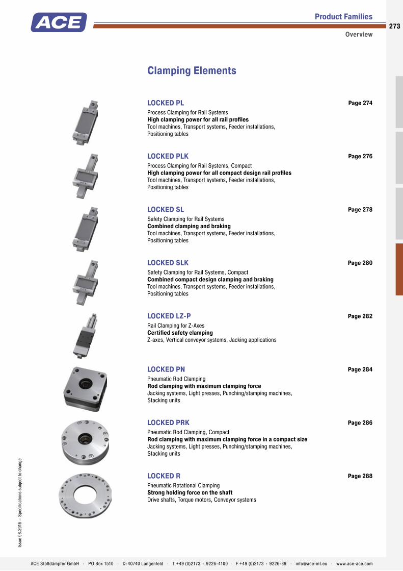
Product Families
Overview
Clamping Elements
LOCKED PL Process Clamping for Rail Systems High clamping power for all rail profi lesTool machines, Transport systems, Feeder installations, Positioning tables
Page 274
LOCKED PLK Process Clamping for Rail Systems, Compact High clamping power for all compact design rail profi lesTool machines, Transport systems, Feeder installations, Positioning tables
Page 276
LOCKED SL Safety Clamping for Rail Systems Combined clamping and brakingTool machines, Transport systems, Feeder installations, Positioning tables
Page 278
LOCKED SLK Safety Clamping for Rail Systems, Compact Combined compact design clamping and brakingTool machines, Transport systems, Feeder installations, Positioning tables
Page 280
LOCKED LZ-P Rail Clamping for Z-Axes Certifi ed safety clampingZ-axes, Vertical conveyor systems, Jacking applications
Page 282
LOCKED PN Pneumatic Rod Clamping Rod clamping with maximum clamping forceJacking systems, Light presses, Punching/stamping machines, Stacking units
Page 284
LOCKED PRK Pneumatic Rod Clamping, Compact Rod clamping with maximum clamping force in a compact sizeJacking systems, Light presses, Punching/stamping machines, Stacking units
Page 286
LOCKED R Pneumatic Rotational Clamping Strong holding force on the shaftDrive shafts, Torque motors, Conveyor systems
Page 288
273Is
sue
08.2
016
– Sp
ecifi
catio
ns s
ubje
ct to
cha
nge
ACE Stoßdämpfer GmbH . PO Box 1510 . D-40740 Langenfeld . T +49 (0)2173 - 9226-4100 . F +49 (0)2173 - 9226-89 . [email protected] . www.ace-ace.com

Linear Guide
2. Holding Block (Option)
Spring Diaphragm
Steel Clamping Pad
Air Inlet Connection (both sides possible)
Rubber Sealed Coating
Holding Block with two Threaded Holes
Technical Data
Always on the safe side: The process clamping elements from the LOCKED series PL clamp directly onto the clear area of guide rails on linear modules with forces of up to 10,000 N. They are individually adjusted to the linear guide being used and are available for all rail sizes from 20 to 65 mm and profi les from all renowned manufacturers.
This series achieves 100 % clamping force even on greased rails, due to the steel pads that are used. It offers optimum static clamping with up to 1 million cycles or up to 500 emergency braking operations. These process clamping elements also impress with their low system costs in comparison with hydraulic and electric solutions.
The various models from the LOCKED Series PL from ACE are mainly used on machine tools and customised machines.
LOCKED PLClamping Elements High clamping power for all rail profi les
Clamping Elements
Process Clamping for Rail Systems
Holding forces: 540 N to 10,000 NRail sizes: 20 mm to 65 mmClamping cycles: 1,000,000/500. Higher values on request.Mounting: In any positionOperating pressure: 4 bar (automotive) or 6 barMaterial: Outer body: Tool steelPneumatic medium: Dried, fi ltered airOperating temperature range: 15 °C to 45 °C
Application fi eld: Tool machines, Transport systems, Feeder installations, Positioning tablesNote: If requested installation drawings of the respective types are provided.On request: Special designs on request.
274
Issu
e 08
.201
6 –
Spec
ifi ca
tions
sub
ject
to c
hang
e
ACE Stoßdämpfer GmbH . PO Box 1510 . D-40740 Langenfeld . T +49 (0)2173 - 9226-4100 . F +49 (0)2173 - 9226-89 . [email protected] . www.ace-ace.com

Linear Guide
2. Holding Block (Option)
Spring Diaphragm
Steel Clamping Pad
Air Inlet Connection (both sides possible)
Rubber Sealed Coating
Holding Block with two Threaded Holes
Clamping Elements PL
Process Clamping for Rail Systems
B
GH
A
N
L
A
N
L
D E D
C
D
M
PL
The calculation and selection of the most suitable clamping element should be carried out or be approved by ACE.
Ordering Example PL45-2-6B-XLinear Process ClampingRail Nominal Size 45 mmNumber of Holding Blocks 26B = 6 bar Type4B = 4 bar TypeSeries Number assigned by ACE
Complete details required when ordering Operating pressure: 4 bar or 6 bar
Performance and DimensionsLow Carriage High Carriage
TYPES
1 Holding force
N
Operating pressure
barB
mmC
mmD
mmE
mmL
mmA
mmG
mmH
mmA
mmG
mmH
mmM N Weight
kgPL20-1-4B 540 4 43 12 6 - 97.5 13.5 30 19.5 - - - M5 M5 0.32PL20-1-6B 900 6 43 12 6 - 97.5 13.5 30 19.5 - - - M5 M5 0.32PL25-1-4B 780 4 47 16 6 - 117.5 15.5 36 25 19.5 40 29 M6 M5 0.50PL25-1-6B 1,200 6 47 16 6 - 117.5 15.5 36 25 19.5 40 29 M6 M5 0.50PL30-1-4B 1,100 4 59 18 10 - 126.5 17.0 42 29.5 20.0 45 32.5 M8 M5 0.90PL30-1-6B 1,800 6 59 18 10 - 126.5 17.0 42 29.5 20.0 45 32.5 M8 M5 0.90PL35-1-4B 1,800 4 69 22 10 - 156.5 22.5 48 35 29.5 55 42 M10 G1/8 1.26PL35-1-6B 2,800 6 69 22 10 - 156.5 22.5 48 35 29.5 55 42 M10 G1/8 1.26PL45-1-4B 2,400 4 80 28 10 - 176.5 26.5 60 42 36.5 70 52 M10 G1/8 2.30PL45-1-6B 4,000 6 80 28 10 - 176.5 26.5 60 42 36.5 70 52 M10 G1/8 2.30PL45-2-4B 2,400 4 80 28 10 171.2 191.5 26.5 60 42 36.5 70 52 M10 G1/8 2.30PL45-2-6B 4,000 6 80 28 10 171.2 191.5 26.5 60 42 36.5 70 52 M10 G1/8 2.30PL55-1-4B 3,600 4 98 34 12.5 - 202.5 28.0 70 49 38.0 80 59 M10 G1/8 3.90PL55-1-6B 6,000 6 98 34 12.5 - 202.5 28.0 70 49 38.0 80 59 M10 G1/8 3.90PL55-2-4B 3,600 4 98 34 12.5 196.2 221.5 28.0 70 49 38.0 80 59 M10 G1/8 4.10PL55-2-6B 6,000 6 98 34 12.5 196.2 221.5 28.0 70 49 38.0 80 59 M10 G1/8 4.10PL65-1-4B 6,000 4 120 44 15 - 259.5 38.0 90 64 48.0 100 74 M12 G1/8 5.00PL65-1-6B 10,000 6 120 44 15 - 259.5 38.0 90 64 48.0 100 74 M12 G1/8 5.00PL65-2-4B 6,000 4 120 44 15 251.5 281.5 38.0 90 64 48.0 100 74 M12 G1/8 5.20PL65-2-6B 10,000 6 120 44 15 251.5 281.5 38.0 90 64 48.0 100 74 M12 G1/8 5.20
1 The holding forces as shown in the capacity chart were determined on dry rails for roller systems (STAR, INA). Different holding forces may occur for other rails.
275Is
sue
08.2
016
– Sp
ecifi
catio
ns s
ubje
ct to
cha
nge
ACE Stoßdämpfer GmbH . PO Box 1510 . D-40740 Langenfeld . T +49 (0)2173 - 9226-4100 . F +49 (0)2173 - 9226-89 . [email protected] . www.ace-ace.com

Linear Guide
2. Holding Block (Option)
Spring Diaphragm
Steel Clamping Pad
Air Inlet Connection (both sides possible)
Rubber Sealed Coating
Holding Block with two Threaded Holes
Technical Data
Small can clamp perfectly too: The LOCKED-Series PLK clamping elements are more compact than the Series PL components. They also clamp directly onto the respective linear guide, suit all standard rail sizes from 15 to 55 mm and profi les from the known suppliers and are extremely reliable and space-saving.
Thanks to the patented spring steel plate system, the LOCKED-Series PLK achieves clamping and holding forces of up to 2,100 N with the shortest reaction times when vented. The LOCKED-Series PLK achieves 100 % clamping force due to the steel pads that are used, even on greased rails. The clamping elements represent the maximum holding forces. Whether in the 4 or 6 bar version, they are good for up to 1 million cycles or up to 500 emergency braking operations.
Representatives of the LOCKED-Series PLK from ACE are primarily used in mechanical engineering and customised machines.
LOCKED PLKClamping Elements High clamping power for all compact design rail profi les
Clamping Elements
Process Clamping for Rail Systems, Compact
Holding forces: 300 N to 2,100 NRail sizes: 15 mm to 55 mmClamping cycles: 1,000,000/500. Higher values on request.Mounting: In any positionOperating pressure: 4 bar (automotive) or 6 barMaterial: Outer body: Tool steelPneumatic medium: Dried, fi ltered airOperating temperature range: 15 °C to 45 °C
Application fi eld: Tool machines, Transport systems, Feeder installations, Positioning tablesNote: If requested installation drawings of the respective types are provided.On request: Special designs on request.
276
Issu
e 08
.201
6 –
Spec
ifi ca
tions
sub
ject
to c
hang
e
ACE Stoßdämpfer GmbH . PO Box 1510 . D-40740 Langenfeld . T +49 (0)2173 - 9226-4100 . F +49 (0)2173 - 9226-89 . [email protected] . www.ace-ace.com

Clamping Elements PLK
Process Clamping for Rail Systems, Compact
L
A
N
HG
B L
A
N
M
D E
C
D D
PLK
The calculation and selection of the most suitable clamping element should be carried out or be approved by ACE.
Ordering Example PLK55-2-6B-XLinear Process Clamping CompactRail Nominal Size 55 mmNumber of Holding Blocks 26B = 6 bar Type4B = 4 bar TypeSeries Number assigned by ACE
Complete details required when ordering Operating pressure: 4 bar or 6 bar
Performance and DimensionsLow Carriage High Carriage
TYPES
1 Holding force
N
Operating pressure
barB
mmC
mmD
mmE
mmL
mmA
mmG
mmH
mmA
mmG
mmH
mmM N Weight
kgPLK15-1-4B 300 4 45 12 5 - 55.5 14.0 24 18 14.0 - - M5 M5 0.50PLK15-1-6B 450 6 45 12 5 - 55.5 14.0 24 18 14.0 - - M5 M5 0.50PLK20-1-4B 430 4 54 16 5 - 55.5 16.0 30 22 16.0 - - M6 M5 0.60PLK20-1-6B 650 6 54 16 5 - 55.5 16.0 30 22 16.0 - - M6 M5 0.60PLK25-1-4B 530 4 75 16 5 - 55.5 16.0 36 25.5 16.0 40 29.5 M6 M5 0.70PLK25-1-6B 800 6 75 16 5 - 55.5 16.0 36 25.5 16.0 40 29.5 M6 M5 0.70PLK30-1-4B 750 4 82 18 8.75 - 67 21.0 42 30 21.0 45 33 M8 M5 0.90PLK30-1-6B 1,150 6 82 18 8.75 - 67 21.0 42 30 21.0 45 33 M8 M5 0.90PLK35-1-4B 820 4 96 22 8.75 - 67 21.2 48 35 21.2 55 42 M10 G1/8 1.27PLK35-1-6B 1,250 6 96 22 8.75 - 67 21.2 48 35 21.2 55 42 M10 G1/8 1.27PLK45-1-4B 950 4 116 28 10 - 80 27.5 60 45 27.5 70 55 M10 G1/8 2.00PLK45-1-6B 1,500 6 116 28 10 - 80 27.5 60 45 27.5 70 55 M10 G1/8 2.00PLK45-2-4B 950 4 116 28 10 72 92 27.5 60 45 27.5 70 55 M10 G1/8 2.20PLK45-2-6B 1,500 6 116 28 10 72 92 27.5 60 45 27.5 70 55 M10 G1/8 2.20PLK55-1-4B 1,300 4 136 34 10 - 100 30.5 70 49 30.5 80 59 M10 G1/8 2.80PLK55-1-6B 2,100 6 136 34 10 - 100 30.5 70 49 30.5 80 59 M10 G1/8 2.80PLK55-2-4B 1,300 4 136 34 10 92 112 30.5 70 49 30.5 80 59 M10 G1/8 3.00PLK55-2-6B 2,100 6 136 34 10 92 112 30.5 70 49 30.5 80 59 M10 G1/8 3.00
1 The holding forces as shown in the capacity chart were determined on dry rails for roller systems (STAR, INA). Different holding forces may occur for other rails.
277Is
sue
08.2
016
– Sp
ecifi
catio
ns s
ubje
ct to
cha
nge
ACE Stoßdämpfer GmbH . PO Box 1510 . D-40740 Langenfeld . T +49 (0)2173 - 9226-4100 . F +49 (0)2173 - 9226-89 . [email protected] . www.ace-ace.com

Linear Guide
2. Holding Block (Option)
Spring Diaphragm
Sintered Metal Brake Pad
Air Inlet Connection (both sides possible)
Rubber Sealed Coating
Holding Block with two Threaded Holes
Technical Data
Always on the safe side: The safety clamping elements from the LOCKED series SL clamp and brake directly on the clear area of guide rails on linear modules with forces of up to 10,000 N. They are individually adjusted to the linear guide being used and are available for all rail sizes from 20 to 65 mm and profi les from all renowned manufacturers.
Special brake pads made of low wear sintered metal are used for the additional emergency stop braking functions in safety clamping elements from the LOCKED series SL. The SL series offer optimum static clamping with a service life up to 1 million cycles or up to 500 emergency braking operations. They also offer low system costs in comparison with hydraulic and electric solutions.
The LOCKED-Series SL is particularly used in machinery and special purpose machines.
LOCKED SLClamping Elements Combined clamping and braking
Clamping Elements
Safety Clamping for Rail Systems
Holding forces: 540 N to 10,000 NRail sizes: 20 mm to 65 mmClamping cycles/emergency use: 1,000,000/500Higher values on request.Mounting: In any positionOperating pressure: 4 bar (automotive) or 6 barMaterial: Outer body: Tool steelPneumatic medium: Dried, fi ltered airOperating temperature range: 15 °C to 45 °C
Application fi eld: Tool machines, Transport systems, Feeder installations, Positioning tablesNote: If requested installation drawings of the respective types are provided.
278
Issu
e 08
.201
6 –
Spec
ifi ca
tions
sub
ject
to c
hang
e
ACE Stoßdämpfer GmbH . PO Box 1510 . D-40740 Langenfeld . T +49 (0)2173 - 9226-4100 . F +49 (0)2173 - 9226-89 . [email protected] . www.ace-ace.com

Linear Guide
2. Holding Block (Option)
Spring Diaphragm
Sintered Metal Brake Pad
Air Inlet Connection (both sides possible)
Rubber Sealed Coating
Holding Block with two Threaded Holes
Clamping Elements SL
Safety Clamping for Rail Systems
B
GH
A
N
L
A
N
L
D E D
C
D
M
SL
The calculation and selection of the most suitable clamping element should be carried out or be approved by ACE.
Ordering Example SL55-1-4B-XLinear Safety ClampingRail Nominal Size 55 mmNumber of Holding Blocks 14B = 4 bar Type6B = 6 bar TypeSeries Number assigned by ACE
Complete details required when ordering Operating pressure: 4 bar or 6 bar
Performance and DimensionsLow Carriage High Carriage
TYPES
1 Holding force
N
Operating pressure
barB
mmC
mmD
mmE
mmL
mmA
mmG
mmH
mmA
mmG
mmH
mmM N Weight
kgSL20-1-4B 540 4 43 12 6 - 97.5 13.5 30 19.5 - - - M5 M5 0.32SL20-1-6B 900 6 43 12 6 - 97.5 13.5 30 19.5 - - - M5 M5 0.32SL25-1-4B 780 4 47 16 6 - 117.5 15.5 36 25 19.5 40 29 M6 M5 0.50SL25-1-6B 1,200 6 47 16 6 - 117.5 15.5 36 25 19.5 40 29 M6 M5 0.50SL30-1-4B 1,100 4 59 18 10 - 126.5 17.0 42 29.5 20.0 45 32.5 M8 M5 0.90SL30-1-6B 1,800 6 59 18 10 - 126.5 17.0 42 29.5 20.0 45 32.5 M8 M5 0.90SL35-1-4B 1,800 4 69 22 10 - 156.5 22.5 48 35 29.5 55 42 M10 G1/8 1.26SL35-1-6B 2,800 6 69 22 10 - 156.5 22.5 48 35 29.5 55 42 M10 G1/8 1.26SL45-1-4B 2,400 4 80 28 10 - 176.5 26.5 60 42 36.5 70 52 M10 G1/8 2.30SL45-1-6B 4,000 6 80 28 10 - 176.5 26.5 60 42 36.5 70 52 M10 G1/8 2.30SL45-2-4B 2,400 4 80 28 10 171.2 191.5 26.5 60 42 36.5 70 52 M10 G1/8 2.30SL45-2-6B 4,000 6 80 28 10 171.2 191.5 26.5 60 42 36.5 70 52 M10 G1/8 2.30SL55-1-4B 3,600 4 98 34 12.5 - 202.5 28.0 70 49 38.0 80 59 M10 G1/8 3.90SL55-1-6B 6,000 6 98 34 12.5 - 202.5 28.0 70 49 38.0 80 59 M10 G1/8 3.90SL55-2-4B 3,600 4 98 34 12.5 196.2 221.5 28.0 70 49 38.0 80 59 M10 G1/8 3.90SL55-2-6B 6,000 6 98 34 12.5 196.2 221.5 28.0 70 49 38.0 80 59 M10 G1/8 3.90SL65-1-4B 6,000 4 120 44 15 - 259.5 38.0 90 64 48.0 100 74 M12 G1/8 5.00SL65-1-6B 10,000 6 120 44 15 - 259.5 38.0 90 64 48.0 100 74 M12 G1/8 5.00SL65-2-4B 6,000 4 120 44 15 251.2 281.5 38.0 90 64 48.0 100 74 M12 G1/8 5.20SL65-2-6B 10,000 6 120 44 15 251.2 281.5 38.0 90 64 48.0 100 74 M12 G1/8 5.20
1 The holding forces as shown in the capacity chart were determined on dry rails for roller systems (STAR, INA). Different holding forces may occur for other rails.
279Is
sue
08.2
016
– Sp
ecifi
catio
ns s
ubje
ct to
cha
nge
ACE Stoßdämpfer GmbH . PO Box 1510 . D-40740 Langenfeld . T +49 (0)2173 - 9226-4100 . F +49 (0)2173 - 9226-89 . [email protected] . www.ace-ace.com
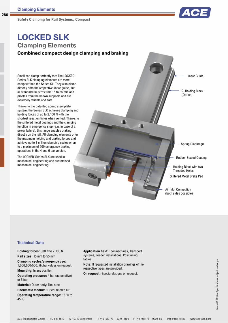
Linear Guide
2. Holding Block (Option)
Spring Diaphragm
Sintered Metal Brake Pad
Air Inlet Connection (both sides possible)
Rubber Sealed Coating
Holding Block with two Threaded Holes
Technical Data
Small can clamp perfectly too: The LOCKED-Series SLK clamping elements are more compact than the Series SL. They also clamp directly onto the respective linear guide, suit all standard rail sizes from 15 to 55 mm and profi les from the known suppliers and are extremely reliable and safe.
Thanks to the patented spring steel plate system, the Series SLK achieves clamping and holding forces of up to 2,100 N with the shortest reaction times when vented. Thanks to the sintered metal coatings and the clamping function in emergency stop (e.g. in case of a power failure), this range enables braking directly on the rail. All clamping elements offer the maximum holding and braking forces and achieve up to 1 million clamping cycles or up to a maximum of 500 emergency braking operations in the 4 and 6 bar version.
The LOCKED-Series SLK are used in mechanical engineering and customised mechanical engineering.
LOCKED SLKClamping Elements Combined compact design clamping and braking
Clamping Elements
Safety Clamping for Rail Systems, Compact
Holding forces: 300 N to 2,100 NRail sizes: 15 mm to 55 mmClamping cycles/emergency use: 1,000,000/500. Higher values on request.Mounting: In any positionOperating pressure: 4 bar (automotive) or 6 barMaterial: Outer body: Tool steelPneumatic medium: Dried, fi ltered airOperating temperature range: 15 °C to 45 °C
Application fi eld: Tool machines, Transport systems, Feeder installations, Positioning tablesNote: If requested installation drawings of the respective types are provided.On request: Special designs on request.
280
Issu
e 08
.201
6 –
Spec
ifi ca
tions
sub
ject
to c
hang
e
ACE Stoßdämpfer GmbH . PO Box 1510 . D-40740 Langenfeld . T +49 (0)2173 - 9226-4100 . F +49 (0)2173 - 9226-89 . [email protected] . www.ace-ace.com
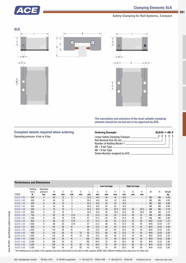
Linear Guide
2. Holding Block (Option)
Spring Diaphragm
Sintered Metal Brake Pad
Air Inlet Connection (both sides possible)
Rubber Sealed Coating
Holding Block with two Threaded Holes
Clamping Elements SLK
Safety Clamping for Rail Systems, Compact
L
A
N
HG
B L
A
N
M
D E
C
D D
SLK
The calculation and selection of the most suitable clamping element should be carried out or be approved by ACE.
Ordering Example SLK45-1-4B-XLinear Safety Clamping CompactRail Nominal Size 45 mmNumber of Holding Blocks 14B = 4 bar Type6B = 6 bar TypeSeries Number assigned by ACE
Complete details required when ordering Operating pressure: 4 bar or 6 bar
Performance and DimensionsLow Carriage High Carriage
TYPES
1 Holding force
N
Operating pressure
barB
mmC
mmD
mmE
mmL
mmA
mmG
mmH
mmA
mmG
mmH
mmM N Weight
kgSLK15-1-4B 300 4 45 12 5 - 55.5 14.0 24 18 14.0 - - M5 M5 0.50SLK15-1-6B 450 6 45 12 5 - 55.5 14.0 24 18 14.0 - - M5 M5 0.50SLK20-1-4B 430 4 54 16 5 - 55.5 16.0 30 22 16.0 - - M6 M5 0.60SLK20-1-6B 650 6 54 16 5 - 55.5 16.0 30 22 16.0 - - M6 M5 0.60SLK25-1-4B 530 4 75 16 5 - 55.5 16.0 36 25.5 16.0 40 29.5 M6 M5 0.70SLK25-1-6B 800 6 75 16 5 - 55.5 16.0 36 25.5 16.0 40 29.5 M6 M5 0.70SLK30-1-4B 750 4 82 18 8.75 - 67 21.0 42 30 21.0 45 33 M8 M5 0.90SLK30-1-6B 1,150 6 82 18 8.75 - 67 21.0 42 30 21.0 45 33 M8 M5 0.90SLK35-1-4B 820 4 96 22 8.75 - 67 21.2 48 35 21.2 55 42 M10 G1/8 1.27SLK35-1-6B 1,250 6 96 22 8.75 - 67 21.2 48 35 21.2 55 42 M10 G1/8 1.27SLK45-1-4B 950 4 116 28 10 - 80 27.5 60 45 27.5 70 55 M10 G1/8 2.00SLK45-1-6B 1,500 6 116 28 10 - 80 27.5 60 45 27.5 70 55 M10 G1/8 2.00SLK45-2-4B 950 4 116 28 10 72 92 27.5 60 45 27.5 70 55 M10 G1/8 2.20SLK45-2-6B 1,500 6 116 28 10 72 92 27.5 60 45 27.5 70 55 M10 G1/8 2.20SLK55-1-4B 1,300 4 136 34 10 - 100 30.5 70 49 30.5 80 59 M10 G1/8 2.80SLK55-1-6B 2,100 6 136 34 10 - 100 30.5 70 49 30.5 80 59 M10 G1/8 2.80SLK55-2-4B 1,300 4 136 34 10 92 112 30.5 70 49 30.5 80 59 M10 G1/8 3.00SLK55-2-6B 2,100 6 136 34 10 92 112 30.5 70 49 30.5 80 59 M10 G1/8 3.00
1 The holding forces as shown in the capacity chart were determined on dry rails for roller systems (STAR, INA). Different holding forces may occur for other rails.
281Is
sue
08.2
016
– Sp
ecifi
catio
ns s
ubje
ct to
cha
nge
ACE Stoßdämpfer GmbH . PO Box 1510 . D-40740 Langenfeld . T +49 (0)2173 - 9226-4100 . F +49 (0)2173 - 9226-89 . [email protected] . www.ace-ace.com
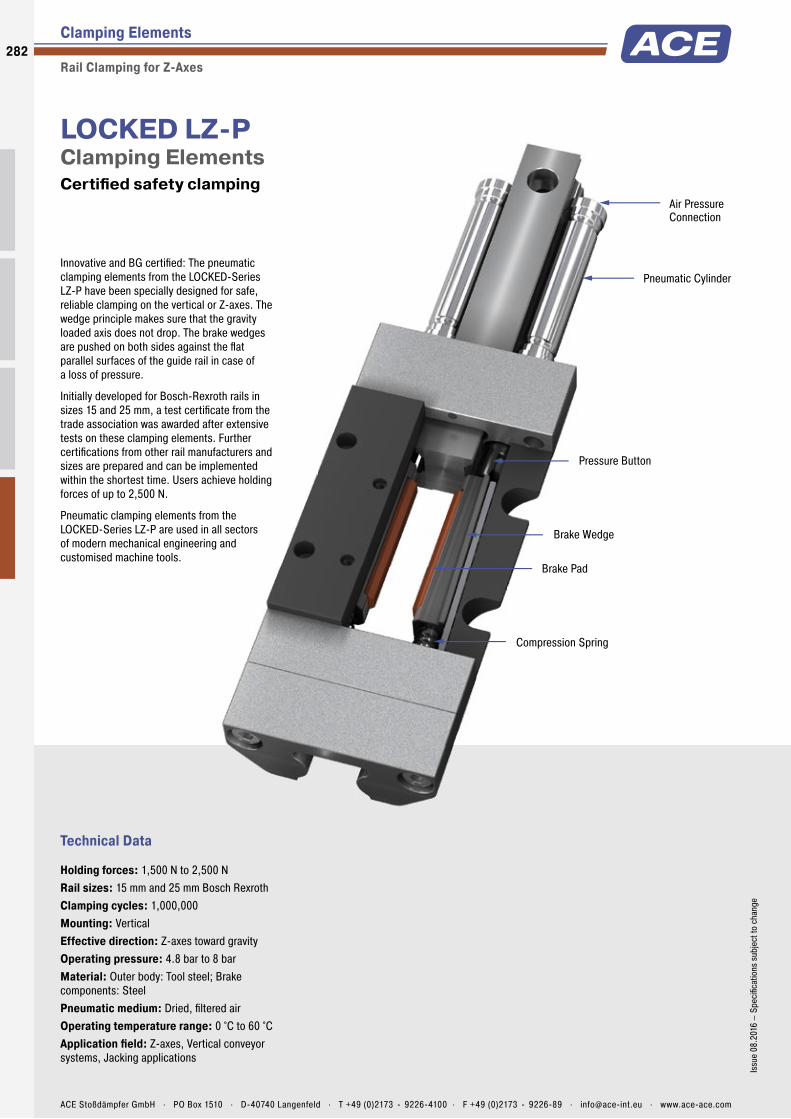
Pneumatic Cylinder
Air PressureConnection
Brake Wedge
Compression Spring
Pressure Button
Brake Pad
Technical Data
Innovative and BG certifi ed: The pneumatic clamping elements from the LOCKED-Series LZ-P have been specially designed for safe, reliable clamping on the vertical or Z-axes. The wedge principle makes sure that the gravity loaded axis does not drop. The brake wedges are pushed on both sides against the fl at parallel surfaces of the guide rail in case of a loss of pressure.
Initially developed for Bosch-Rexroth rails in sizes 15 and 25 mm, a test certifi cate from the trade association was awarded after extensive tests on these clamping elements. Further certifi cations from other rail manufacturers and sizes are prepared and can be implemented within the shortest time. Users achieve holding forces of up to 2,500 N.
Pneumatic clamping elements from the LOCKED-Series LZ-P are used in all sectors of modern mechanical engineering and customised machine tools.
LOCKED LZ-PClamping Elements Certifi ed safety clamping
Clamping Elements
Rail Clamping for Z-Axes
Holding forces: 1,500 N to 2,500 NRail sizes: 15 mm and 25 mm Bosch RexrothClamping cycles: 1,000,000Mounting: VerticalEffective direction: Z-axes toward gravityOperating pressure: 4.8 bar to 8 barMaterial: Outer body: Tool steel; Brake components: SteelPneumatic medium: Dried, fi ltered airOperating temperature range: 0 °C to 60 °CApplication fi eld: Z-axes, Vertical conveyor systems, Jacking applications
282
Issu
e 08
.201
6 –
Spec
ifi ca
tions
sub
ject
to c
hang
e
ACE Stoßdämpfer GmbH . PO Box 1510 . D-40740 Langenfeld . T +49 (0)2173 - 9226-4100 . F +49 (0)2173 - 9226-89 . [email protected] . www.ace-ace.com

Pneumatic Cylinder
Air PressureConnection
Brake Wedge
Compression Spring
Pressure Button
Brake Pad
Clamping Elements LZ-P
Rail Clamping for Z-Axes
L
C
A D
Attachment Screws M
Air Pressure Connection N
HG
BLZ-P
The calculation and selection of the most suitable clamping element should be carried out or be approved by ACE.
Ordering Example LZ-P15-XProcess Clamping Z-AxisRail Nominal Size 15 mmSeries Number assigned by ACE
Performance and Dimensions
TYPESHolding force
NA
mmB
mmC
mmD
mmG
mmH
mmL
mmM N Weight
kgLZ-P15-X 1,500 30 47 40 34 24 20 108.5 M4 M3 0.4LZ-P25-X 2,500 30 70 56 70 36 30 170.0 M6 M5 1.3
283Is
sue
08.2
016
– Sp
ecifi
catio
ns s
ubje
ct to
cha
nge
ACE Stoßdämpfer GmbH . PO Box 1510 . D-40740 Langenfeld . T +49 (0)2173 - 9226-4100 . F +49 (0)2173 - 9226-89 . [email protected] . www.ace-ace.com

Cover Plate
Air Connection
Membrane with Spring Steel Diaphragm
Clamping Unit (n = 1-3)
Base Plate
Connections for optional Proximity Switches
Clamping Sleeve
Wiper (optional)
Technical Data
Immediate clamping in case of loss of pneumatics: Suitable for rods with diameters of 20 to 40 mm, the clamping elements from the LOCKED-Series PN absorb the forces axially and rotationally. With holding forces of up to 36,000 N, they reach or exceed the levels of hydraulic clamps. The system costs are however lower.
Alongside clamping in both directions of motion, the LOCKED-PN also surprises with its compact design. They need less installation space and enable short rod lengths. For versions with ISO pneumatic cylinders, the base plate is coordinated to the dimensions of the fl ange sizes of standard cylinders according to ISO 15552. Users appreciate the modular system. It allows several segments to be stacked so that the necessary clamping force can be attained for every application.
The areas of application for the LOCKED- Series PN are mechanical engineering and machine tools.
LOCKED PNClamping Elements Rod clamping with maximum clamping force
Clamping Elements
Pneumatic Rod Clamping
Holding torques: 15 Nm to 720 NmHolding forces: 1,400 N to 36,000 NRod diameter: Ø 20 mm to Ø 40 mmClamping cycles: 1,000,000. Higher values on request.Mounting: In any positionOperating pressure: 4 bar (automotive) or 6 barMaterial: Outer body: Tool steelPneumatic medium: Dried, fi ltered airOperating temperature range: 10 °C to 45 °C
Application fi eld: Jacking systems, Light presses, Punching/stamping machines, Stacking unitsNote: When mounting, use hardened piston rod.On request: Special designs as for example special diameters and accessories available on request.
284
Issu
e 08
.201
6 –
Spec
ifi ca
tions
sub
ject
to c
hang
e
ACE Stoßdämpfer GmbH . PO Box 1510 . D-40740 Langenfeld . T +49 (0)2173 - 9226-4100 . F +49 (0)2173 - 9226-89 . [email protected] . www.ace-ace.com

Cover Plate
Air Connection
Membrane with Spring Steel Diaphragm
Clamping Unit (n = 1-3)
Base Plate
Connections for optional Proximity Switches
Clamping Sleeve
Wiper (optional)
Clamping Elements PN
Pneumatic Rod Clamping
E
D
M8x1 forInitiators
Air Connection N
Ø C
A
B
PN
The calculation and selection of the most suitable clamping element should be carried out or be approved by ACE.
Ordering Example PN80-25-3-4BRod Clamping Standard ModelCylinder Nominal Diameter 80 mmRod Diameter 25 mmNumber of Clamping Units 36B = 6 bar Type4B = 4 bar Type
Performance and Dimensions
TYPES
1 Holding forceN
Holding torqueNm
Operating pressurebar
Amm
Bmm
Cmm
Dmm
Emm
N Weightkg
PN63-20-1-4B 1,400 15 4 75 56.5 8.5 41.5 2.1 M5 0.70PN63-20-1-6B 2,000 20 6 75 56.5 8.5 41.5 2.1 M5 0.70PN63-20-2-4B 2,520 25 4 75 56.5 8.5 59.5 2.1 M5 1.13PN63-20-2-6B 3,600 35 6 75 56.5 8.5 59.5 2.1 M5 1.13PN63-20-3-4B 3,780 35 4 75 56.5 8.5 77.5 2.1 M5 1.56PN63-20-3-6B 5,400 50 6 75 56.5 8.5 77.5 2.1 M5 1.56PN80-25-1-4B 2,100 25 4 96 72 10.5 43.5 2.14 G1/8 1.30PN80-25-1-6B 3,000 35 6 96 72 10.5 43.5 2.14 G1/8 1.30PN80-25-2-4B 3,780 40 4 96 72 10.5 63.5 2.14 G1/8 2.20PN80-25-2-6B 5,400 60 6 96 72 10.5 63.5 2.14 G1/8 2.20PN80-25-3-4B 5,670 65 4 96 72 10.5 83.5 2.14 G1/8 3.10PN80-25-3-6B 8,100 95 6 96 72 10.5 83.5 2.14 G1/8 3.10PN125-40-1-4B 7,000 140 4 145 110 13 51.6 3 G1/8 3.65PN125-40-1-6B 10,000 200 6 145 110 13 51.6 3 G1/8 3.65PN125-40-2-4B 12,600 250 4 145 110 13 75.2 3 G1/8 5.85PN125-40-2-6B 18,000 360 6 145 110 13 75.2 3 G1/8 5.85PN125-40-3-4B 18,900 375 4 145 110 13 98.8 3 G1/8 8.05PN125-40-3-6B 27,000 540 6 145 110 13 98.8 3 G1/8 8.05PN125-40-4-4B 25,200 500 4 145 110 13 122.4 3 G1/8 10.25PN125-40-4-6B 36,000 720 6 145 110 13 122.4 3 G1/8 10.25
1 The listed holding forces are reached under optimum conditions. We recommend a safety factor of > 10 %. Please note that surface, material and cleanliness of the rod as well as wear and tear and the use of rod wipers lead to different holding forces. Test the clamping needed for series production or safety applications in its speci?c application environment and measure the actual values.
285Is
sue
08.2
016
– Sp
ecifi
catio
ns s
ubje
ct to
cha
nge
ACE Stoßdämpfer GmbH . PO Box 1510 . D-40740 Langenfeld . T +49 (0)2173 - 9226-4100 . F +49 (0)2173 - 9226-89 . [email protected] . www.ace-ace.com
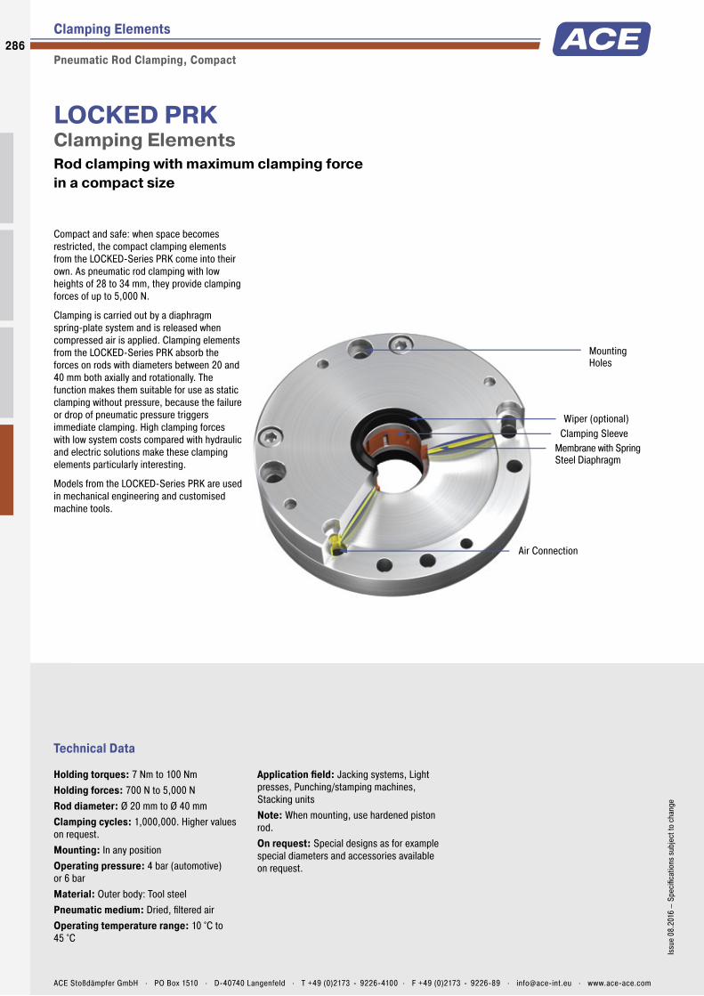
Mounting Holes
Air Connection
Membrane with Spring Steel Diaphragm
Clamping SleeveWiper (optional)
Technical Data
Compact and safe: when space becomes restricted, the compact clamping elements from the LOCKED-Series PRK come into their own. As pneumatic rod clamping with low heights of 28 to 34 mm, they provide clamping forces of up to 5,000 N.
Clamping is carried out by a diaphragm spring-plate system and is released when compressed air is applied. Clamping elements from the LOCKED-Series PRK absorb the forces on rods with diameters between 20 and 40 mm both axially and rotationally. The function makes them suitable for use as static clamping without pressure, because the failure or drop of pneumatic pressure triggers immediate clamping. High clamping forces with low system costs compared with hydraulic and electric solutions make these clamping elements particularly interesting.
Models from the LOCKED-Series PRK are used in mechanical engineering and customised machine tools.
LOCKED PRKClamping Elements Rod clamping with maximum clamping force in a compact size
Clamping Elements
Pneumatic Rod Clamping, Compact
Holding torques: 7 Nm to 100 NmHolding forces: 700 N to 5,000 NRod diameter: Ø 20 mm to Ø 40 mmClamping cycles: 1,000,000. Higher values on request.Mounting: In any positionOperating pressure: 4 bar (automotive) or 6 barMaterial: Outer body: Tool steelPneumatic medium: Dried, fi ltered airOperating temperature range: 10 °C to 45 °C
Application fi eld: Jacking systems, Light presses, Punching/stamping machines, Stacking unitsNote: When mounting, use hardened piston rod.On request: Special designs as for example special diameters and accessories available on request.
286
Issu
e 08
.201
6 –
Spec
ifi ca
tions
sub
ject
to c
hang
e
ACE Stoßdämpfer GmbH . PO Box 1510 . D-40740 Langenfeld . T +49 (0)2173 - 9226-4100 . F +49 (0)2173 - 9226-89 . [email protected] . www.ace-ace.com
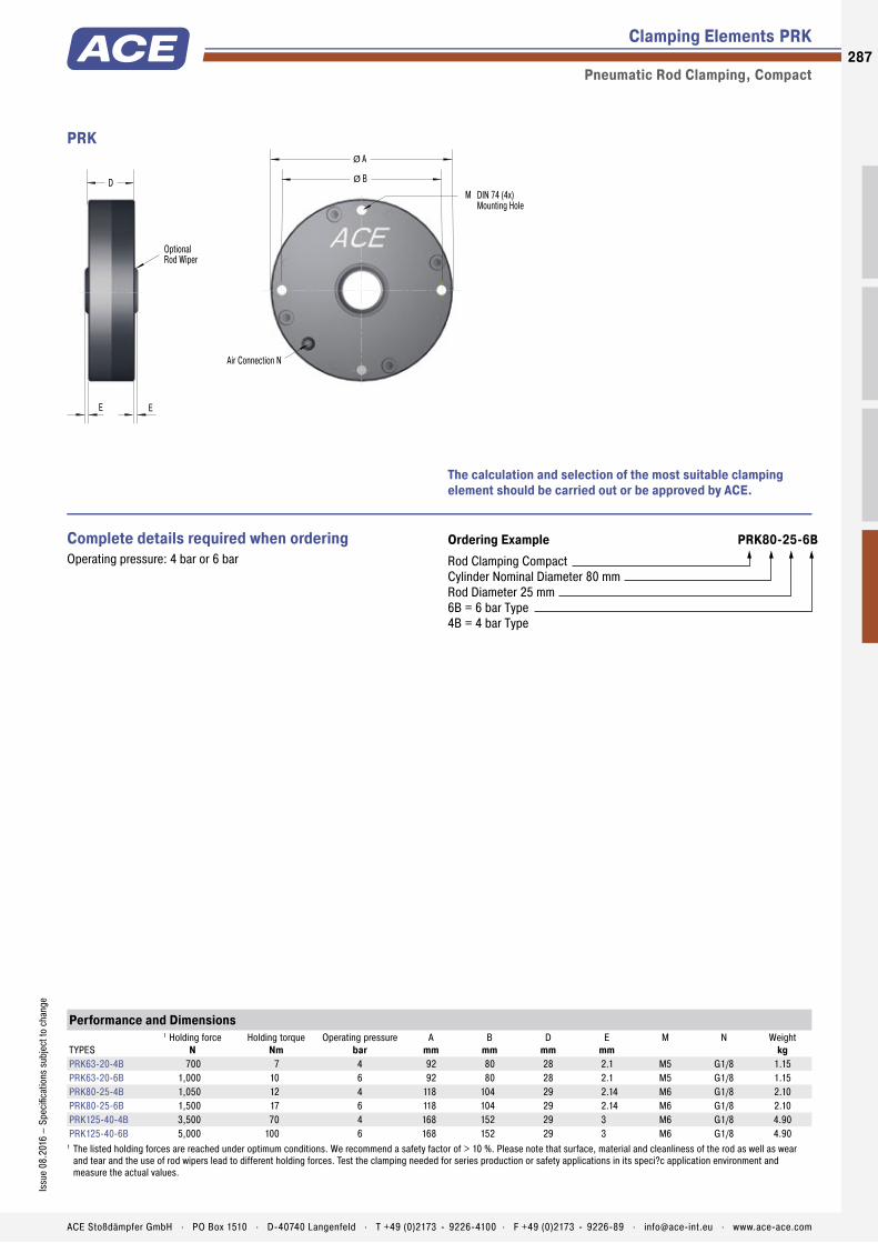
Mounting Holes
Air Connection
Membrane with Spring Steel Diaphragm
Clamping SleeveWiper (optional)
Clamping Elements PRK
Pneumatic Rod Clamping, Compact
Air Connection N
M
Ø A
Ø B
DIN 74 (4x)Mounting Hole
D
E
OptionalRod Wiper
E
PRK
The calculation and selection of the most suitable clamping element should be carried out or be approved by ACE.
Ordering Example PRK80-25-6BRod Clamping CompactCylinder Nominal Diameter 80 mmRod Diameter 25 mm6B = 6 bar Type4B = 4 bar Type
Complete details required when ordering Operating pressure: 4 bar or 6 bar
Performance and Dimensions
TYPES
1 Holding forceN
Holding torqueNm
Operating pressurebar
Amm
Bmm
Dmm
Emm
M N Weightkg
PRK63-20-4B 700 7 4 92 80 28 2.1 M5 G1/8 1.15PRK63-20-6B 1,000 10 6 92 80 28 2.1 M5 G1/8 1.15PRK80-25-4B 1,050 12 4 118 104 29 2.14 M6 G1/8 2.10PRK80-25-6B 1,500 17 6 118 104 29 2.14 M6 G1/8 2.10PRK125-40-4B 3,500 70 4 168 152 29 3 M6 G1/8 4.90PRK125-40-6B 5,000 100 6 168 152 29 3 M6 G1/8 4.90
1 The listed holding forces are reached under optimum conditions. We recommend a safety factor of > 10 %. Please note that surface, material and cleanliness of the rod as well as wear and tear and the use of rod wipers lead to different holding forces. Test the clamping needed for series production or safety applications in its speci?c application environment and measure the actual values.
287Is
sue
08.2
016
– Sp
ecifi
catio
ns s
ubje
ct to
cha
nge
ACE Stoßdämpfer GmbH . PO Box 1510 . D-40740 Langenfeld . T +49 (0)2173 - 9226-4100 . F +49 (0)2173 - 9226-89 . [email protected] . www.ace-ace.com
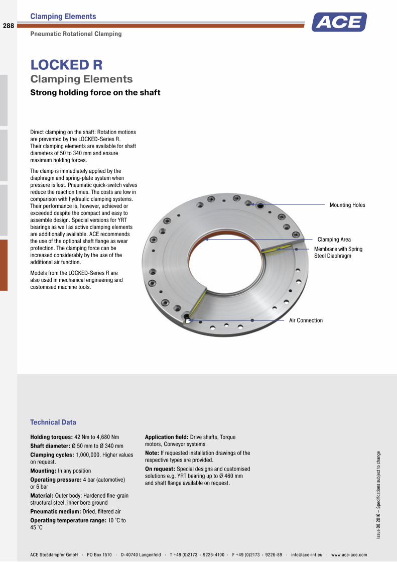
Mounting Holes
Air Connection
Membrane with Spring Steel Diaphragm
Clamping Area
Technical Data
Direct clamping on the shaft: Rotation motions are prevented by the LOCKED-Series R. Their clamping elements are available for shaft diameters of 50 to 340 mm and ensure maximum holding forces.
The clamp is immediately applied by the diaphragm and spring-plate system when pressure is lost. Pneumatic quick-switch valves reduce the reaction times. The costs are low in comparison with hydraulic clamping systems. Their performance is, however, achieved or exceeded despite the compact and easy to assemble design. Special versions for YRT bearings as well as active clamping elements are additionally available. ACE recommends the use of the optional shaft fl ange as wear protection. The clamping force can be increased considerably by the use of the additional air function.
Models from the LOCKED-Series R are also used in mechanical engineering and customised machine tools.
LOCKED RClamping Elements Strong holding force on the shaft
Clamping Elements
Pneumatic Rotational Clamping
Holding torques: 42 Nm to 4,680 NmShaft diameter: Ø 50 mm to Ø 340 mmClamping cycles: 1,000,000. Higher values on request.Mounting: In any positionOperating pressure: 4 bar (automotive) or 6 barMaterial: Outer body: Hardened fi ne-grain structural steel, inner bore groundPneumatic medium: Dried, fi ltered airOperating temperature range: 10 °C to 45 °C
Application fi eld: Drive shafts, Torque motors, Conveyor systemsNote: If requested installation drawings of the respective types are provided.On request: Special designs and customised solutions e.g. YRT bearing up to Ø 460 mm and shaft fl ange available on request.
288
Issu
e 08
.201
6 –
Spec
ifi ca
tions
sub
ject
to c
hang
e
ACE Stoßdämpfer GmbH . PO Box 1510 . D-40740 Langenfeld . T +49 (0)2173 - 9226-4100 . F +49 (0)2173 - 9226-89 . [email protected] . www.ace-ace.com
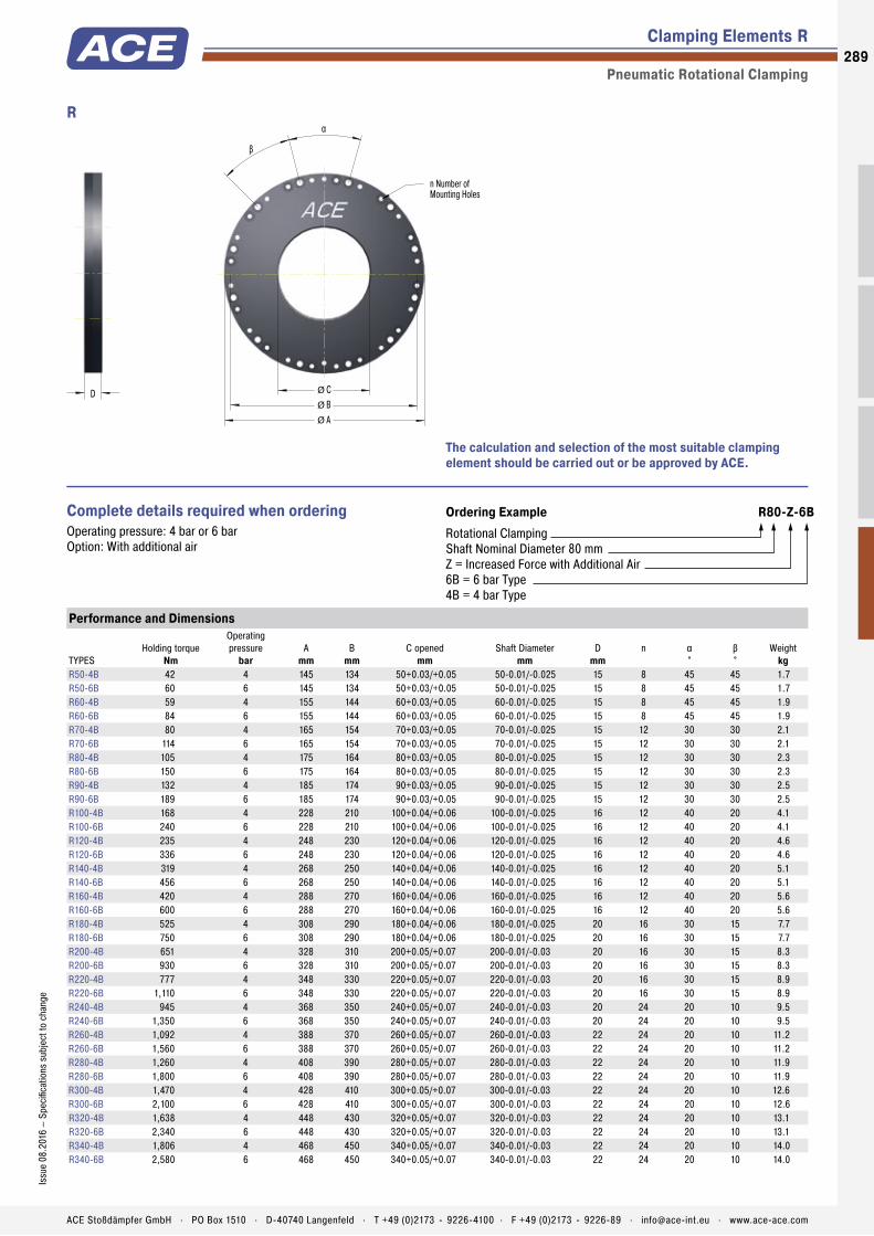
Mounting Holes
Air Connection
Membrane with Spring Steel Diaphragm
Clamping Area
Clamping Elements R
Pneumatic Rotational Clamping
n Number ofMounting Holes
α
β
D Ø CØ BØ A
R
The calculation and selection of the most suitable clamping element should be carried out or be approved by ACE.
Ordering Example R80-Z-6BRotational ClampingShaft Nominal Diameter 80 mmZ = Increased Force with Additional Air6B = 6 bar Type4B = 4 bar Type
Complete details required when ordering Operating pressure: 4 bar or 6 bar Option: With additional air
Performance and Dimensions
TYPESHolding torque
Nm
Operating pressure
barA
mmB
mmC opened
mmShaft Diameter
mmD
mmn α
°β°
Weightkg
R50-4B 42 4 145 134 50+0.03/+0.05 50-0.01/-0.025 15 8 45 45 1.7R50-6B 60 6 145 134 50+0.03/+0.05 50-0.01/-0.025 15 8 45 45 1.7R60-4B 59 4 155 144 60+0.03/+0.05 60-0.01/-0.025 15 8 45 45 1.9R60-6B 84 6 155 144 60+0.03/+0.05 60-0.01/-0.025 15 8 45 45 1.9R70-4B 80 4 165 154 70+0.03/+0.05 70-0.01/-0.025 15 12 30 30 2.1R70-6B 114 6 165 154 70+0.03/+0.05 70-0.01/-0.025 15 12 30 30 2.1R80-4B 105 4 175 164 80+0.03/+0.05 80-0.01/-0.025 15 12 30 30 2.3R80-6B 150 6 175 164 80+0.03/+0.05 80-0.01/-0.025 15 12 30 30 2.3R90-4B 132 4 185 174 90+0.03/+0.05 90-0.01/-0.025 15 12 30 30 2.5R90-6B 189 6 185 174 90+0.03/+0.05 90-0.01/-0.025 15 12 30 30 2.5R100-4B 168 4 228 210 100+0.04/+0.06 100-0.01/-0.025 16 12 40 20 4.1R100-6B 240 6 228 210 100+0.04/+0.06 100-0.01/-0.025 16 12 40 20 4.1R120-4B 235 4 248 230 120+0.04/+0.06 120-0.01/-0.025 16 12 40 20 4.6R120-6B 336 6 248 230 120+0.04/+0.06 120-0.01/-0.025 16 12 40 20 4.6R140-4B 319 4 268 250 140+0.04/+0.06 140-0.01/-0.025 16 12 40 20 5.1R140-6B 456 6 268 250 140+0.04/+0.06 140-0.01/-0.025 16 12 40 20 5.1R160-4B 420 4 288 270 160+0.04/+0.06 160-0.01/-0.025 16 12 40 20 5.6R160-6B 600 6 288 270 160+0.04/+0.06 160-0.01/-0.025 16 12 40 20 5.6R180-4B 525 4 308 290 180+0.04/+0.06 180-0.01/-0.025 20 16 30 15 7.7R180-6B 750 6 308 290 180+0.04/+0.06 180-0.01/-0.025 20 16 30 15 7.7R200-4B 651 4 328 310 200+0.05/+0.07 200-0.01/-0.03 20 16 30 15 8.3R200-6B 930 6 328 310 200+0.05/+0.07 200-0.01/-0.03 20 16 30 15 8.3R220-4B 777 4 348 330 220+0.05/+0.07 220-0.01/-0.03 20 16 30 15 8.9R220-6B 1,110 6 348 330 220+0.05/+0.07 220-0.01/-0.03 20 16 30 15 8.9R240-4B 945 4 368 350 240+0.05/+0.07 240-0.01/-0.03 20 24 20 10 9.5R240-6B 1,350 6 368 350 240+0.05/+0.07 240-0.01/-0.03 20 24 20 10 9.5R260-4B 1,092 4 388 370 260+0.05/+0.07 260-0.01/-0.03 22 24 20 10 11.2R260-6B 1,560 6 388 370 260+0.05/+0.07 260-0.01/-0.03 22 24 20 10 11.2R280-4B 1,260 4 408 390 280+0.05/+0.07 280-0.01/-0.03 22 24 20 10 11.9R280-6B 1,800 6 408 390 280+0.05/+0.07 280-0.01/-0.03 22 24 20 10 11.9R300-4B 1,470 4 428 410 300+0.05/+0.07 300-0.01/-0.03 22 24 20 10 12.6R300-6B 2,100 6 428 410 300+0.05/+0.07 300-0.01/-0.03 22 24 20 10 12.6R320-4B 1,638 4 448 430 320+0.05/+0.07 320-0.01/-0.03 22 24 20 10 13.1R320-6B 2,340 6 448 430 320+0.05/+0.07 320-0.01/-0.03 22 24 20 10 13.1R340-4B 1,806 4 468 450 340+0.05/+0.07 340-0.01/-0.03 22 24 20 10 14.0R340-6B 2,580 6 468 450 340+0.05/+0.07 340-0.01/-0.03 22 24 20 10 14.0
289Is
sue
08.2
016
– Sp
ecifi
catio
ns s
ubje
ct to
cha
nge
ACE Stoßdämpfer GmbH . PO Box 1510 . D-40740 Langenfeld . T +49 (0)2173 - 9226-4100 . F +49 (0)2173 - 9226-89 . [email protected] . www.ace-ace.com

Clamping Elements R-Z
Pneumatic Rotational Clamping
n Number ofMounting Holes
α
β
D Ø CØ BØ A
R-Z
The calculation and selection of the most suitable clamping element should be carried out or be approved by ACE.
Ordering Example R80-Z-6BRotational ClampingShaft Nominal Diameter 80 mmZ = Increased Force with Additional Air6B = 6 bar Type4B = 4 bar Type
Complete details required when ordering Operating pressure: 4 bar or 6 bar Option: With additional air
Performance and Dimensions
TYPESHolding torque
Nm
Operating pressure
barA
mmB
mmC opened
mmShaft Diameter
mmD
mmn α
°β°
Weightkg
R50-Z-4B 76 4 145 134 50+0.03/+0.05 50-0.01/-0.025 15 8 45 45 1.7R50-Z-6B 108 6 145 134 50+0.03/+0.05 50-0.01/-0.025 15 8 45 45 1.7R60-Z-4B 107 4 155 144 60+0.03/+0.05 60-0.01/-0.025 15 8 45 45 1.9R60-Z-6B 153 6 155 144 60+0.03/+0.05 60-0.01/-0.025 15 8 45 45 1.9R70-Z-4B 147 4 165 154 70+0.03/+0.05 70-0.01/-0.025 15 12 30 30 2.1R70-Z-6B 210 6 165 154 70+0.03/+0.05 70-0.01/-0.025 15 12 30 30 2.1R80-Z-4B 189 4 175 164 80+0.03/+0.05 80-0.01/-0.025 15 12 30 30 2.3R80-Z-6B 270 6 175 164 80+0.03/+0.05 80-0.01/-0.025 15 12 30 30 2.3R90-Z-4B 239 4 185 174 90+0.03/+0.05 90-0.01/-0.025 15 12 30 30 2.5R90-Z-6B 342 6 185 174 90+0.03/+0.05 90-0.01/-0.025 15 12 30 30 2.5R100-Z-4B 294 4 228 210 100+0.04/+0.06 100-0.01/-0.025 16 12 40 20 4.1R100-Z-6B 420 6 228 210 100+0.04/+0.06 100-0.01/-0.025 16 12 40 20 4.1R120-Z-4B 420 4 248 230 120+0.04/+0.06 120-0.01/-0.025 16 12 40 20 4.6R120-Z-6B 600 6 248 230 120+0.04/+0.06 120-0.01/-0.025 16 12 40 20 4.6R140-Z-4B 588 4 268 250 140+0.04/+0.06 140-0.01/-0.025 16 12 40 20 5.1R140-Z-6B 840 6 268 250 140+0.04/+0.06 140-0.01/-0.025 16 12 40 20 5.1R160-Z-4B 756 4 288 270 160+0.04/+0.06 160-0.01/-0.025 16 12 40 20 5.6R160-Z-6B 1,080 6 288 270 160+0.04/+0.06 160-0.01/-0.025 16 12 40 20 5.6R180-Z-4B 966 4 308 290 180+0.04/+0.06 180-0.01/-0.025 20 16 30 15 7.7R180-Z-6B 1,380 6 308 290 180+0.04/+0.06 180-0.01/-0.025 20 16 30 15 7.7R200-Z-4B 1,176 4 328 310 200+0.05/+0.07 200-0.01/-0.03 20 16 30 15 8.3R200-Z-6B 1,680 6 328 310 200+0.05/+0.07 200-0.01/-0.03 20 16 30 15 8.3R220-Z-4B 1,428 4 348 330 220+0.05/+0.07 220-0.01/-0.03 20 16 30 15 8.9R220-Z-6B 2,040 6 348 330 220+0.05/+0.07 220-0.01/-0.03 20 16 30 15 8.9R240-Z-4B 1,680 4 368 350 240+0.05/+0.07 240-0.01/-0.03 20 24 20 10 8.9R240-Z-6B 2,400 6 368 350 240+0.05/+0.07 240-0.01/-0.03 20 24 20 10 8.9R260-Z-4B 1,974 4 388 370 260+0.05/+0.07 260-0.01/-0.03 22 24 20 10 11.2R260-Z-6B 2,820 6 388 370 260+0.05/+0.07 260-0.01/-0.03 22 24 20 10 11.2R280-Z-4B 2,268 4 408 390 280+0.05/+0.07 280-0.01/-0.03 22 24 20 10 11.9R280-Z-6B 3,240 6 408 390 280+0.05/+0.07 280-0.01/-0.03 22 24 20 10 11.9R300-Z-4B 2,604 4 428 410 300+0.05/+0.07 300-0.01/-0.03 22 24 20 10 12.6R300-Z-6B 3,720 6 428 410 300+0.05/+0.07 300-0.01/-0.03 22 24 20 10 12.6R320-Z-4B 2,940 4 448 430 320+0.05/+0.07 320-0.01/-0.03 22 24 20 10 13.1R320-Z-6B 4,200 6 448 430 320+0.05/+0.07 320-0.01/-0.03 22 24 20 10 13.1R340-Z-4B 3,276 4 468 450 340+0.05/+0.07 340-0.01/-0.03 22 24 20 10 14.0R340-Z-6B 4,680 6 468 450 340+0.05/+0.07 340-0.01/-0.03 22 24 20 10 14.0
290
Issu
e 08
.201
6 –
Spec
ifica
tions
sub
ject
to c
hang
e
ACE Stoßdämpfer GmbH . PO Box 1510 . D-40740 Langenfeld . T +49 (0)2173 - 9226-4100 . F +49 (0)2173 - 9226-89 . [email protected] . www.ace-ace.com

Application Examples
Clamping Elements
SL
Special LOCKED SL elements for emergency stopsIn order to secure the processing position of a special lathe in both the horizontal and the vertical axis, ACE LOCKED elements of the type SL35-1-6B are installed. They have the further advantage of preventing slippage through the vertical axis in the case of a malfunction. The products used in the SL-series not only have the correct track width and offer very high process clamping forces of up to 10,000 N, but can also apply the same force as an emergency-stop braking function. This is due to the specially integrated brake linings made of low-wear sintered metal.
m
ACE clamping and safety elements maintain a rock-solid hold on the axes in special lathes and secure the predetermined positions both horizontally and vertically RASOMA Werkzeugmaschinen GmbH, 04720 Döbeln, Germany
SLK
Secure rail clampingACE clamping elements secure machines in the tyre industry. The goods accumulator/compensator of a material dispenser carries meandering, coiled, highly tear resistant material strips, which are fed at high speed to a tyre-manufacturing machine. To prevent damaging the machine, innovative type SLK25-1-6B clamping elements are employed.
m
Secure material accumulator
291Is
sue
08.2
016
– Sp
ecifi
catio
ns s
ubje
ct to
cha
nge
ACE Stoßdämpfer GmbH . PO Box 1510 . D-40740 Langenfeld . T +49 (0)2173 - 9226-4100 . F +49 (0)2173 - 9226-89 . [email protected] . www.ace-ace.com
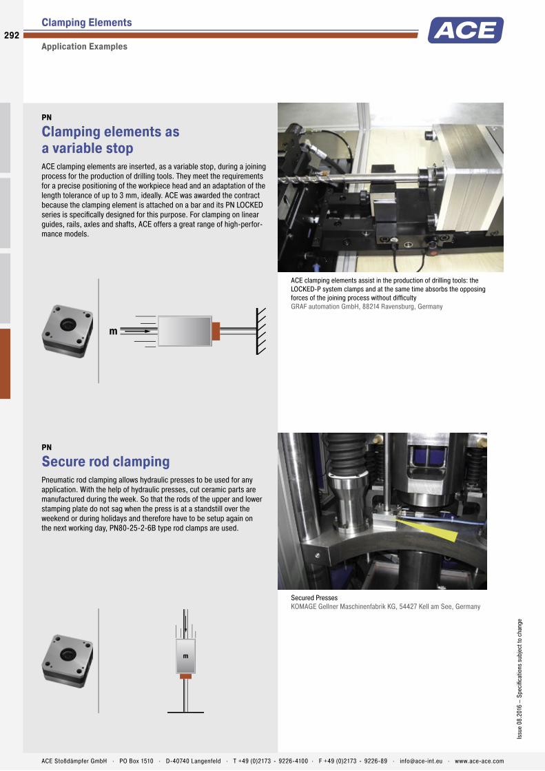
Clamping Elements
Application Examples
PN
Clamping elements as a variable stopACE clamping elements are inserted, as a variable stop, during a joining process for the production of drilling tools. They meet the requirements for a precise positioning of the workpiece head and an adaptation of the length tolerance of up to 3 mm, ideally. ACE was awarded the contract because the clamping element is attached on a bar and its PN LOCKED series is specifi cally designed for this purpose. For clamping on linear guides, rails, axles and shafts, ACE offers a great range of high-perfor-mance models.
m
ACE clamping elements assist in the production of drilling tools: the LOCKED-P system clamps and at the same time absorbs the opposing forces of the joining process without diffi culty GRAF automation GmbH, 88214 Ravensburg, Germany
PN
Secure rod clampingPneumatic rod clamping allows hydraulic presses to be used for any application. With the help of hydraulic presses, cut ceramic parts are manufactured during the week. So that the rods of the upper and lower stamping plate do not sag when the press is at a standstill over the weekend or during holidays and therefore have to be setup again on the next working day, PN80-25-2-6B type rod clamps are used.
m
Secured Presses KOMAGE Gellner Maschinenfabrik KG, 54427 Kell am See, Germany
292
Issu
e 08
.201
6 –
Spec
ifi ca
tions
sub
ject
to c
hang
e
ACE Stoßdämpfer GmbH . PO Box 1510 . D-40740 Langenfeld . T +49 (0)2173 - 9226-4100 . F +49 (0)2173 - 9226-89 . [email protected] . www.ace-ace.com

Automation Control Equipment
Notes293
ACE Stoßdämpfer GmbH . PO Box 1510 . D-40740 Langenfeld . T +49 (0)2173 - 9226-4100 . F +49 (0)2173 - 9226-89 . [email protected] . www.ace-ace.com

294
Issu
e 08
.201
6 –
Spec
ifi ca
tions
sub
ject
to c
hang
e
ACE Stoßdämpfer GmbH . PO Box 1510 . D-40740 Langenfeld . T +49 (0)2173 - 9226-4100 . F +49 (0)2173 - 9226-89 . [email protected] . www.ace-ace.com
Issu
e 08
.201
6 –
Spec
ifi ca
tions
sub
ject
to c
hang
e
ACE Stoßdämpfer GmbH . PO Box 1510 . D-40740 Langenfeld . T +49 (0)2173 - 9226-4100 . F +49 (0)2173 - 9226-89 . [email protected] . www.ace-ace.com
ACE Training & Information Material
Free Services
Free and Convenient in your Premises
Whether in the training vehicle or through lectures: we have a lot to tell. Images, tests and con-crete products at your location convey information much more quickly and plausibly than speech or written materials.
In our free specialised lectures we clearly demonstrate the function and mode of operation of the damping elements. Fast, compact and completely tailored to suit you. ACE presentations include video material, a lot of application images, drop tester and a pneumatic demonstration unit along with original “live” products.
We illuminate kinetic energies and the impact on production processes, design and mode of operation of shock absorbers, we compare techniques, calculate, perform tests and show typical applications.
Even more Compact: Training in the ACE Demonstration Vehicle
In 60 minutes, everything about automation control, motion control, vibration control and ACE safety products. Right at your premises on the parking lot.
Learn how you can increase your production, go easy on your machines, reduce noise and vibrations, simplify designs and save costs.
Ideal for smaller groups of about 8 people.
ACE Expertise Compact Lectures, training courses and a new demonstration vehicle
295Is
sue
08.2
016
– Sp
ecifi
catio
ns s
ubje
ct to
cha
nge
ACE Stoßdämpfer GmbH . PO Box 1510 . D-40740 Langenfeld . T +49 (0)2173 - 9226-4100 . F +49 (0)2173 - 9226-89 . [email protected] . www.ace-ace.com
Fax RequestOur free and fast service
Do you need the new main catalogue? Are you interested in ACE lectures and presentations? Or a training course in the ACE demonstration vehicle with field representatives of your choice?
We offer compact, tailored presentation packages. These illustrate the function and mode of operation of the ACE products – quickly and easily. At our place or yours!
ACE Training & Information Material
Fax +49 (0)2173 - 9226-89
Yes. We are interested in
the new ACE catalogue
a training in the demonstration vehicle
product presentations in our premises
a lecture at our site
technical assistance at our site
Please copy, complete and fax to +49 (0)2173 - 9226-89
Your contact information
Department
Function
Name
Company
Fax
Telephone
Address
Internet
ZIP Code / City
Please also use our contact form atwww.ace-ace.com
Topic Automation Control
Motion Control
Vibration Control
Safety Products

296
Issu
e 08
.201
6 –
Spec
ifica
tions
sub
ject
to c
hang
e
ACE Stoßdämpfer GmbH . PO Box 1510 . D-40740 Langenfeld . T +49 (0)2173 - 9226-4100 . F +49 (0)2173 - 9226-89 . [email protected] . www.ace-ace.com
Distributors Worldwide
in Countries without ACE Facility
ARGENTINA CAMOZZI NEUMATICA S.A.
Prof. Dr. Pedro Chutro 3048 1437 Buenos Aires, Argentina T +54 11 49110816 F +54 11 49124191 www.camozzi.com.ar
AUSTRIA ACE STOSSDÄMPFER GMBH
Albert-Einstein-Straße 15, 40764 Langenfeld, Germany T +49 2173-9226-4000 F +49 2173-9226-29 www.ace-ace.de (distributors on request)
BELARUS BIBUS (BY) COOO
8th Per. Ilyicha 13a, office 2.1 246013 Gomel, Belarus T +375 232 29 31 39 F +375 232 39 59 02 www.bibus.by (not distributor for gas springs and HB dampers) Gas spring & HB damper specialists: TECHVITASBEL LLC F. Skaryny str. 15B-3 220114 Minsk, Belarus T +375 17 396 63 83 F +375 17 396 63 82 www.techvitas.by (not distributor for shock absorbers, TUBUS, SLAB)
BELGIUM ACE STOSSDÄMPFER GMBH
Albert-Einstein-Straße 15, 40764 Langenfeld, Germany T +32 11-960736 F +32 11-960737 www.ace-ace.com (distributors on request)
BOSNIA AND HERZEGOVINA BIBUS DOO
Karadordeva, 76311 Dvorovi – Bijelijna Bosnia and Herzegovina T +387 55 423 444 F +387 55 423 444 www.bibus.ba (not distributor for gas springs and HB dampers) For gas springs & HB dampers: ACE STOSSDÄMPFER GMBH Albert-Einstein-Straße 15, 40764 Langenfeld, Germany T +49 2173-9226-4100 F +49 2173-9226-89 www.ace-ace.com
BRAZIL OBR EQUIPAMENTOS
INDUSTRIAIS LTDA. Rua Florianópolis, 431, Mooca-São Paulo – SP. CEP 03185-050, Brazil T +55 11-2067 3698 / 0800704 3698 www.obr.com.br
BULGARIA BIBUS BULGARIA LTD.
Tzvetan Lazarov Blv. 2, floor 2, 1574 Sofia, Bulgaria T +359 2 971 98 08 F +359 2 927 32 64 www.bibus.bg (not distributor for gas springs and HB dampers) For gas springs & HB dampers: ACE STOSSDÄMPFER GMBH Albert-Einstein-Straße 15, 40764 Langenfeld , Germany T +49 2173-9226-4100 F +49 2173-9226-89 www.ace-ace.com
GREECE PNEUMATEC INDUSTRIAL
AUTOMATION SYSTEMS 91 Spirou Patsi Street, Athens 11855, Greece T +302 1 03412101 / 3413930 F +302 1 03413930
HUNGARY BIBUS KFT.
Almáskert út 9, 2220 Vecsés, Hungary T +36 29 557 763 F +36 29 557 777 www.bibus.hu (not distributor for gas springs and HB dampers) Gas spring & HB damper specialists: DUNA CONSULTING KFT. Gábor Áron u. 18, 2013 Pomáz, Hungary T +36 1 433 4700, +36-30 26 36 576 F +36 1 264 8900 www.acegazrugo.hu
INDIA SHREEJI MARKETING CORPORATION
2& 3, 1st Floor, Pride Plaza, Mumbai-Pune Road Pimpri, Pune - 411018, India T +91 20 2742 0897 F +91 20 2742 0997 www.shreejimkt.com
IRELAND IRISH PNEUMATIC SERVICES LTD.
5A M7 Business Park Newhall, Naas, Co. Kildare, Ireland T +353 45-872590 F +353 45-872595 www.irishpneumaticservices.com
ISRAEL ILAN & GAVISH AUTOMATION SERVICE LTD.
26, Shenkar Street, Qiryat-arie 49513 PO Box 10118, 49001 Petah-Tiqva, Israel T +972 39 22 18 24 F +972 39 24 07 61 www.ilan-gavish.co.il
ITALY R.T.I. S.R.L.
Via Chambery 93/107V, 10142 Torino, Italy T +39 011-70 00 53 / 70 02 32 F +39 011-70 01 41 www.rti-to.it
JORDAN ATAFAWOK TRADING EST.
PO Box 921797, Amman 11192, Jordan T +962 64 02 38 73 F +962 65 92 63 25
LATVIA TECHVITAS SIA
38 Daugavas Street, Marupe 2167 Marupes nov., Latvia T +371 27 530 003 F +371 29 847 378 www.techvitas.lv
CHILE TAYLOR AUTOMATIZACION S.A.
Santiago De Uriona 1854, Quinta Normal 8500000 - Santiago, Chile T +56 2 2555 1516 F +56 2 2544 1965 www.taylorsa.cl
CROATIA BIBUS ZAGREB D.O.O.
Anina 91, 10000 Zagreb, Croatia T +385 1 3818 004 F +385 1 3818 005 www.bibus.hr (not distributor for gas springs and HB dampers) For gas springs & HB dampers: ACE STOSSDÄMPFER GMBH Albert-Einstein-Straße 15, 40764 Langenfeld, Germany T +49 2173-9226-4100 F +49 2173-9226-89 www.ace-ace.com
CZECH REPUBLIC BIBUS S.R.O.
Videnska 125, 639 27 Brno, Czech Republic T +420 547 125 300 F +420 547 125 310 www.bibus.cz (not distributor for gas springs and HB dampers) Gas spring & HB damper specialists: MN–SYSTEMS, S.R.O. Na Honech I/5538, 760 05 Zlín, Czech Republic T +420 734 200 172 F +420 246 013 937 www.mnsystems.cz
DENMARK AVN TEKNIK A/S
Dalager 1, 2605 Broendby, Denmark T +45 70 20 04 11 F +45 43 24 55 00 www.avn.dk
ESTONIA TECHVITAS SIA
38 Daugavas Street, Marupe 2167 Marupes nov., Latvia T +371 27 530 003 F +371 29 847 378 www.techvitas.lv
FINLAND NESTEPAINE OY
Makituvantie 11, 01510 Vantaa, Finland T +358 20 765 165 F +358 20 765 7666 www.nestepaine.fi MOVETEC OY Hannuksentie 1, 02270 Espoo, Finland T +358 9 5259 230 F +358 9 5259 2333 www.movetec.fi
FRANCE BIBUS FRANCE
ZI du Chapotin, 233 rue des frères Voisin 69970 Chaponnay, France T +33 4 78 96 80 00 F +33 4 78 96 80 01 www.bibusfrance.fr (not distributor for gas springs and HB dampers) For gas springs & HB dampers: ACE STOSSDÄMPFER GMBH Albert-Einstein-Straße 15, 40764 Langenfeld, Germany T +49 2173-9226-4100 F +49 2173-9226-89 www.ace-ace.com

Issu
e 08
.201
6 –
Spec
ifica
tions
sub
ject
to c
hang
e
ACE Stoßdämpfer GmbH . PO Box 1510 . D-40740 Langenfeld . T +49 (0)2173 - 9226-4100 . F +49 (0)2173 - 9226-89 . [email protected] . www.ace-ace.com
Distributors Worldwide
in Countries without ACE Facility
Distributors in Asia see www.ace-ace.com
LITHUANIA TECHVITAS UAB
Dubysos g. 66A, 94107 Klaipeda, Lithuania T +370 46 355 494 F +370 46 355 493 www.techvitas.lt
LUXEMBOURG ACE STOSSDÄMPFER GMBH
Albert-Einstein-Straße 15, 40764 Langenfeld, Germany T +32 11-960736 F +32 11-960737 www.ace-ace.com (distributors on request)
NETHERLANDS ACE STOSSDÄMPFER GMBH
Albert-Einstein-Straße 15, 40764 Langenfeld, Germany T +31 165-714455 F +31 165-714456 www.ace-ace.com (distributors on request)
NORWAY ACE STOSSDÄMPFER GMBH
Albert-Einstein-Straße 15, 40764 Langenfeld, Germany T +49 2173-9226-4100 F +49 2173-9226-89 www.ace-ace.com HYDNET AB Turebergsvagen 5, 191 47 Sollentuna, Sweden T +46 8 59 470 470 F +46 8 59 470 479 www.hydnet.se
PAKISTAN JJ HYDRAULIC PNEUMATIC
SYSTEMS (PVT) LTD. 41 # Old Ralli Building, Talpur Road, Off, I I Chundrigar Road, Karachi – 74000, Pakistan Dir no. 0092 0333 2229606 T +92 21 32426486 / 32426516 F +92 21 32416807
POLAND BIBUS MENOS SP. Z.O.O.
ul. Spadochroniarzy 18, 80-298 Gdańsk, Poland T +48 58 660 95 70 F +48 58 661 71 32 www.bibusmenos.pl (not distributor for gas springs and HB dampers) Gas spring & HB damper specialists: F.H.U. ELMATIC S.C. ul. Marii Skłodowskiej - Curie 73 A 87-100 Toruń, Poland T / F +48 56 659 16 81 T +48 56 659 15 49, +48-56 653 98 10 www.elmatic.com.pl
PORTUGAL AIRCONTROL INDUSTRIAL S.L.
Alameda Fernao Lopes 31A, Torre 2 - Miraflores 1495-136 Alges (Lisboa), Portugal T +351 21 410 13 57 F +351 21 410 56 08 www.aircontrol.es BIBUS PORTUGAL LDA Centro Empresarial AAA, Rua Ponte da Pedra, 240 – C4 4470-108 Gueifães - Maia, Portugal T +351 22 906 50 50 F +351 22 906 50 53 www.bibus.pt (not distributor for gas springs and HB dampers)
ROMANIA BIBUS SES S.R.L.
134/1 Calea Lugojului, 307200 Ghiroda, Timis, Romania T +40 356 446 500 F +40 356 446 660 www.bibus.ro (not distributor for gas springs and HB dampers) Gas spring & HB damper specialists: D.C. COMPANY S.R.L. Dragos Voda nr. 43, 300351 Timisoara, Romania T +40 722 145 213 F +40 356 800 513 www.ewarehouse.ro
RUSSIA BIBUS O.O.O.
Str Zemskaja 94, 198205 St. Petersburg, Russia T/F +7 812 309 41 51 T +7 800 100 14 52 www.bibus.ru (not distributor for gas springs and HB dampers) Gas spring & HB damper specialists: TEHINNOVATION O.O.O. Krasnodonskaya street 19, building 2, office 17 109386 Moscow, Russia T +7 495 222 06 01 F +7 499 786 42 56 www.tehinnovation.ru
SERBIA BIBUS DOO
Karadordeva, 76311 Dvorovi – Bijelijna Bosnia and Herzegovina T +387 55 423 444 F +387 55 423 444 www.bibus.ba (not distributor for gas springs and HB dampers) For gas springs & HB dampers: ACE STOSSDÄMPFER GMBH Albert-Einstein-Straße 15, 40764 Langenfeld, Germany T +49 2173-9226-4100 F +49 2173-9226-89 www.ace-ace.com
SLOVAKIA BIBUS SK S.R.O.
Trnavska cesta, 94901 Nitra, Slovakia T +421 37 77 77 950 F +421 37 77 77 969 www.bibus.sk (not distributor for gas springs and HB dampers) Gas spring & HB damper specialists: PNEUTRADE S.R.O Rybárska 8, 949 01 Nitra, Slovakia T +421 37 65 24 338 F +421 37 65 55 933 www.pneutrade.sk
SLOVENIA INOTEH D.O.O.
K Zeleznici 7, 2345 Bistrica ob Dravi, Slovenia T +386 (0)2 665 1131 F +386 (0)2 665 2081 www.inoteh.si (not distributor for gas springs and HB dampers) For gas springs & HB dampers: ACE STOSSDÄMPFER GMBH Albert-Einstein-Straße 15, 40764 Langenfeld, Germany T +49 2173-9226-4100 F +49 2173-9226-89 www.ace-ace.com
SOUTH AFRICA PNEUMARK CONTROLS
94A Crompton Street, Pinetown 3610, South Africa T +27 31 701 0421 F +27 86 551 2026 www.pneumark.co.za
SPAIN AIRCONTROL INDUSTRIAL S.L.
Paseo Sarroeta 4 20014 Donostia-San Sebastian, Spain T +34 943 44 50 80 F +34 943 44 51 53 www.aircontrol.es BIBUS SPAIN S.L. Polígono Industrial Porto do Molle Rua do Arroncal, Vial C – Nave 4A 36350 Nigran (Pontevedra), Spain T +34 986 24 72 86 F +34 986 20 92 47 www.bibus.es (not distributor for gas springs and HB dampers)
SWEDEN HYDNET AB
Turebergsvagen 5, 191 47 Sollentuna, Sweden T +46 8 59 470 470 F +46 8 59 470 479 www.hydnet.se
SWITZERLAND BIBUS AG
Allmendstrasse 26, 8320 Fehraltorf, Switzerland T +41 44-877 50 11 F +41 44-877 58 51 www.bibus.ch (not distributor for gas springs and HB dampers) For gas springs & HB dampers: ACE STOSSDÄMPFER GMBH Albert-Einstein-Straße 15, 40764 Langenfeld, Germany T +49 2173-9226-4100 F +49 2173-9226-89 www.ace-ace.com
TURKEY BIBUS OTOMASYON SAN. VE TIC.LTD.STI.
Ziya Gökalp Mh. Bedrettin Dalan Bulv. VIP Plaza No:43-44 İkitelli Başakşehir / İstanbul, Turkey T +90-212 293 82 00 F +90-212 249 88 34 www.bibus.com.tr (not distributor for gas springs and HB dampers) Gas spring & HB damper specialists: POVVER PNÖMATIK A.S. Necatibey Cad. No:44 Kat:2 34425 Karaköy/Istanbul, Turkey T +90 212 293 88 70 F +90 212 293 68 77 www.powerpnomatik.com
UKRAINE BIBUS UKRAINE TOV
1B, Kyivs‘ka Str., Tarasivka 08161 Kyiv region, Ukraine T +380 44 545 44 04 F +380 44 545 54 83 www.bibus.ua (not distributor for gas springs and HB dampers) For gas springs & HB dampers: ACE STOSSDÄMPFER GMBH Albert-Einstein-Straße 15, 40764 Langenfeld, Germany T +49 2173-9226-4100 F +49 2173-9226-89 www.ace-ace.com

ACE Germany The shortest way to the perfect shock absorber
ACE Stoßdämpfer GmbH
PO Box 1510 40740 Langenfeld
Albert-Einstein-Straße 15 40764 Langenfeld
Germany
T +49 (0)2173 - 9226-10 F +49 (0)2173 - 9226-19
[email protected] www.ace-ace.de
JAPAN ACE Controls Japan L.L.C.
City Center Bldg. II 2fl 3-1-42, Chigasaki-minami, Tsuzuki-ku Yokohama, 224-0037, Japan T +81 (0)45 - 945-0123 F +81 (0)45 - 945-0122 www.acecontrols.co.jp
GREAT BRITAIN ACE Fabreeka UK
Unit 404 Easter Park, Haydock Lane Haydock, WA11 9TH, U.K. T +44 (0)1942 - 727 440 F +44 (0)1942 - 717 273 www.acecontrols.co.uk
USA ACE Controls International Inc.
23425 Industrial Park Dr., Farmington Hills Michigan 48335, USA T +1 248 - 476-0213 F +1 248 - 476-2470 www.acecontrols.com
P.R. CHINA ACE Controls (Pinghu) CO. LTD.
No. 888 Changsheng Road 314200 Pinghu, Zhejiang Province, P. R. China T +86 (0)512 - 8860-6699 F +86 (0)512 - 8860-6698 www.acecontrols.cn.com
Global but always near International ACE Sales Locations
Distributors in other countries see pages 296 and 297.


