4 38999 26482 83723 III 5015 26500 Pyle Printed Circuit Board EMI Filter Transient Fiber Optics Options Others Matrix 2 Matrix Pyle Crimp Rear Release Matrix I II III High Speed Contacts SJT Contact Amphenol Aerospace for more information at 800-678-0141 • www.amphenol-aerospace.com Amphenol Aerospace JT/LJT Hermetics Contact Size JT II LJT I TV III TV III Solder Crimp Class H Class Y TV* Service Rating Total Contacts 22D 22M 22 20 16 12 12 (Coax) 10 (Power) 8 (Coax) 8†† (Twinax) 8-2■ P M 2 2 8-3■ X NA P P M 3 3 9-3■ X 9-5★■ Grounded 1 1 8-6 X X P P M 6 6 9-6 X X P P 9-7■ X M 7 7 9-22■ X I 2 2 8-35 X P P M 6 6 9-35 9-35 A35 X P P P 8-44 X P P M 4 4 9-44 X 9-94 ■ ✦ M 2 2 8-97■ X M 4 2 2 8-98 S X P P I 3 3 9-98 9-98 A98 X X P P P 11-2★ 11-2★ B2 X P** I 2 2 10-4 3 I 4 4 11-4 11-4 X S/2 10-5 X X P P I 5 5 11-5 11-5 B5 X X P 11-6■ S I 6 6 10-13 X X P/S P/S M 13 13 11-13 X X P/S P/S 10-35 X P/S P/S M 13 13 11-35 11-35 B35 X P/S P/S P 11-54 ■ X ✦ II 4 4 10-98 X X P/S P/S I 6 6 11-98 11-98 B98 X X P/S P/S P 10-99 X P P I 7 7 11-99 11-99 B99 P X P 12-3 X X ✦ P P II 3 3 13-3■ P 12-4 X X P P I 4 4 13-4★ 13-4★ C4 X X P P P 12-8 X X P P I 8 8 13-8 13-8 C8 X X P P P 13-13■ I, Fiber Optic 4 2** 2 12-22 X P/S P/S M 22 22 13-22 X X P/S P/S 12-35 X P/S P/S M 22 22 13-35 13-35 C35 X P/S P/S P 13-63■ ✦ l 4 2 2 12-98 X X P/S P/S I 10 10 13-98 13-98 C98 X X P/S P/S P 14-4■ 2 I 4 4 15-4■ 15-4■ 2 ✦ 14-5 X X P P II 5 5 15-5★ 15-5★ D5 X X P P P 14-15 X X P P I 15 14 1 15-15 15-15 D15 X X P/S P/S P I 15 14 1 MIL-DTL-38999, Series I LJT, II JT, III TV Insert Availability and Identification Chart Series Series Series Military X Completely tooled. • Majority of tooling is completed (contact Amphenol Aerospace for availability). ✦ Not tooled for 02-R. P Available with Pin contacts only S Available with Socket contacts only P/S Available with Pin contacts or Socket contacts ★ Ground plane proprietary option available. Arrg. 9-5 is exclusively ground plane type. ■ Not Mil-Qualified. ✧ 21-75 is Mil-Qualified with twinax contacts only. Note: MS connector 21-75 is supplied with size 8 twinax. Commercial connector 21-75 is supplied with size 8 coax. * Hermetic inserts - solder termination standard. (Contact Amphenol Aerospace for optional PCB or eyelet termination). ** Two size 16 contacts dedicated to fiber optics. See the Fiber Optic section for more information. *** For use in MIL-STD-1760 applications (see pages 40 & 41). † For RG 180/U and RG 195/U cables only. †† Size 8 Coax and Twinax are interchangeable. (2) Not Tooled for RP or 02RE (3) Pin inserts only, not tooled for RP or 02RE (Consult Sidney, NY for avail.) (5) MS Connector 21-79 has provision for two size 8 coax contacts. Coax contacts are not supplied unless specified by customer.
Transcript
4
3899
9
2648
283
723
III50
1526
500
Pyle
Prin
ted
Circ
uit B
oard
EMI F
ilter
Tran
sien
tFi
ber O
ptic
sO
ptio
ns
Oth
ers
Mat
rix 2
M
atrix
Py
le
Crim
p Re
ar
Rele
ase
Mat
rixI
II
III
Hig
h Sp
eed
Cont
acts
SJT
Contact Amphenol Aerospace for more information at 800-678-0141 • www.amphenol-aerospace.com
AmphenolAerospace
JT/LJT Hermetics Contact Size
JT II LJT I TV III TV III Solder Crimp ClassH
ClassY
TV* Service Rating
Total Contacts
22D 22M 22 20 16 12 12 (Coax)
10 (Power)
8 (Coax)
8†† (Twinax)
8-2■ P M 2 28-3■ X NA P P
M 3 39-3■ X
9-5★■ Grounded 1 18-6 X X P P
M 6 69-6 X X P P9-7■ X M 7 79-22■ X I 2 2
8-35 X P PM 6 6
9-35 9-35 A35 X P P P8-44 X P P
M 4 49-44 X
9-94 ■ ✦ M 2 28-97■ X M 4 2 28-98 S X P P
I 3 39-98 9-98 A98 X X P P P11-2★ 11-2★ B2 X P** I 2 2
10-4 3I 4 4
11-4 11-4 X S/210-5 X X P P
I 5 511-5 11-5 B5 X X P11-6■ S I 6 6
10-13 X X P/S P/SM 13 13
11-13 X X P/S P/S10-35 X P/S P/S
M 13 1311-35 11-35 B35 X P/S P/S P
11-54 ■ X ✦ II 4 410-98 X X P/S P/S
I 6 611-98 11-98 B98 X X P/S P/S P10-99 X P P
I 7 711-99 11-99 B99 P X P
12-3 X X ✦ P PII 3 3
13-3■ P
12-4 X X P PI 4 4
13-4★ 13-4★ C4 X X P P P
12-8 X X P PI 8 8
13-8 13-8 C8 X X P P P
13-13■I, Fiber Optic 4 2** 2
12-22 X P/S P/SM 22 22
13-22 X X P/S P/S12-35 X P/S P/S
M 22 2213-35 13-35 C35 X P/S P/S P
13-63■ ✦ l 4 2 212-98 X X P/S P/S
I 10 1013-98 13-98 C98 X X P/S P/S P
14-4■ 2I 4 4
15-4■ 15-4■ 2 ✦
14-5 X X P PII 5 5
15-5★ 15-5★ D5 X X P P P14-15 X X P P I 15 14 1
15-15 15-15 D15 X X P/S P/S P I 15 14 1
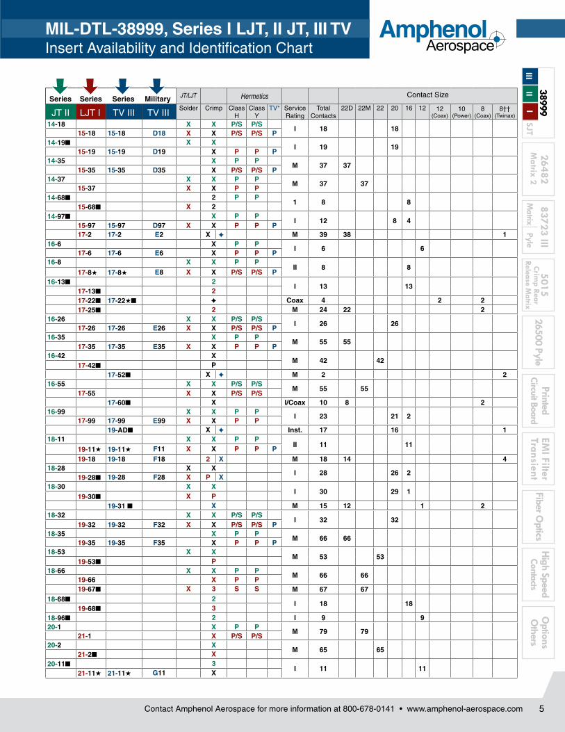
MIL-DTL-38999, Series I LJT, II JT, III TVInsert Availability and Identification Chart
Series Series Series Military
X Completely tooled. • Majority of tooling is completed (contact Amphenol Aerospace for availability).✦ Not tooled for 02-R.P Available with Pin contacts onlyS Available with Socket contacts onlyP/S Available with Pin contacts or Socket contacts★ Ground plane proprietary option available. Arrg. 9-5 is exclusively ground plane type. ■ Not Mil-Qualified.✧ 21-75 is Mil-Qualified with twinax contacts only. Note: MS connector 21-75 is supplied with size 8 twinax. Commercial connector 21-75 is supplied with size 8 coax.
* Hermetic inserts - solder termination standard. (Contact Amphenol Aerospace for optional PCB or eyelet termination). ** Two size 16 contacts dedicated to fiber optics. See the Fiber Optic section for more information.*** For use in MIL-STD-1760 applications (see pages 40 & 41).† For RG 180/U and RG 195/U cables only.†† Size 8 Coax and Twinax are interchangeable.(2) Not Tooled for RP or 02RE(3) Pin inserts only, not tooled for RP or 02RE (Consult Sidney, NY for avail.)(5) MS Connector 21-79 has provision for two size 8 coax contacts. Coax contacts are not supplied unless specified by customer.
5
2648283723 III
501526500 Pyle
PrintedCircuit Board
EMI Filter
TransientFiber O
pticsO
ptions O
thersM
atrix Pyle
Crim
p Rear Release M
atrixM
atrix 2 H
igh SpeedContacts
38999
I II
IIISJT
Contact Amphenol Aerospace for more information at 800-678-0141 • www.amphenol-aerospace.com
AmphenolAerospace
MIL-DTL-38999, Series I LJT, II JT, III TVInsert Availability and Identification Chart
JT/LJT Hermetics Contact Size
Solder Crimp Class H
ClassY
TV* Service Rating
Total Contacts
22D 22M 22 20 16 12 12 (Coax)
10 (Power)
8 (Coax)
8†† (Twinax)
14-18 X X P/S P/SI 18 18
15-18 15-18 D18 X X P/S P/S P14-19■ X X
I 19 1915-19 15-19 D19 X P P P
14-35 X P PM 37 37
15-35 15-35 D35 X P/S P/S P14-37 X X P P
M 37 3715-37 X X P P
14-68■ 2 P P1 8 8
15-68■ X 214-97■ X P P
I 12 8 415-97 15-97 D97 X X P P P17-2 17-2 E2 X ✦ M 39 38 1
19-11★ 19-11★ F11 X X P P P19-18 19-18 F18 2 X M 18 14 4
18-28 X XI 28 26 2
19-28■ 19-28 F28 X P X18-30 X X
I 30 29 119-30■ X P
19-31 ■ X M 15 12 1 218-32 X X P/S P/S
I 32 3219-32 19-32 F32 X X P/S P/S P
18-35 X P PM 66 66
19-35 19-35 F35 X P P P18-53 X X
M 53 5319-53■ P
18-66 X X P PM 66 66
19-66 X P P19-67■ X 3 S S M 67 67
18-68■ 2I 18 18
19-68■ 318-96■ 2 I 9 920-1 X P P
M 79 7921-1 X P/S P/S
20-2 XM 65 65
21-2■ X20-11■ 3
I 11 1121-11★ 21-11★ G11 X
Series Series Series Military
JT II LJT I TV III TV III
6
3899
9
2648
283
723
III50
1526
500
Pyle
Prin
ted
Circ
uit B
oard
EMI F
ilter
Tran
sien
tFi
ber O
ptic
sO
ptio
ns
Oth
ers
Mat
rix 2
M
atrix
Py
le
Crim
p Re
ar
Rele
ase
Mat
rixI
II
III
Hig
h Sp
eed
Cont
acts
SJT
Contact Amphenol Aerospace for more information at 800-678-0141 • www.amphenol-aerospace.com
AmphenolAerospace
JT/LJT Hermetics Contact Size
Solder Crimp H Y TV* Service Rating
Total Contacts
22D 22M 22 20 16 12 12 (Coax)
10 (Power)
8 (Coax)
8†† (Twinax)
20-16 X X P/S P/SII 16 16
21-16★ 21-16★ G16 X X P P P21-25■ X I 25 2521-27■ X I 27 27
21-29 ■ X I 27 19 4 420-35 X P P
M 79 7921-35 21-35 G35 X P/S P/S P
20-39 X X P PI 39 37 2
21-39 21-39 G39 X X P P P20-41 X X P P
I 41 4121-41 21-41 G41 X X P/S P/S P21-75★ 21-75★✧ G75 2 X N M 4 4 (4) 21-79■ 21-79 ■ 2 X II 19 17 2 (5)
22-1 X P/S P/SM 100 100
23-1 X P P22-2 X X P P
M 85 8523-2 X X P P
23-6★■ 23-6★■ P M 6 6
22-14■ 2 ✦I 14 14
23-14■ 23-14 ■ 2 ✦
22-21 X X P PII 21 21
23-21★ 23-21★ H21 X X P P P22-32 X X P P
I 32 3223-32■ X P23-34■ X I 34 34
22-35 X P/S P/SM 100 100
23-35 23-35 H35 X P P P22-53■ P
I 53 5323-53 23-53 H53 X X P/S P/S P
23-54 ■ X M 53 40 9 422-55 X X P P
I 55 5523-55 23-55 H55 X P23-97■ X II 16 1623-99■ X II 11 11
24-1 X P PM 128 128
25-1 X P P24-2 X
M 100 10025-2 X
24-4 X P PI 56 48 8
25-4 25-4 J4 X P25-7■ 25-7 J7 X M Twinax 99 97 2
25-8★ J8 ✦ Twinax 8 825-11*** J11 2 ✦ N 11 2 925-17 ■ ✦ M 42 36 6
24-19■ X P PI 19 19
25-19★ 25-19★ J19 X P25-20■ 25-20*** J20 2 ✦ N 30 10 13 4 3
24-24 X P PI 24 12 12
25-24★ 25-24★ J24 X P P25-26 ■ ✦ I 25 16 5 4
24-29 XI 29 29
25-29★ 25-29★ J29 X X
Series Series Series Military
MIL-DTL-38999, Series I LJT, II JT, III TVInsert Availability and Identification Chart
X Completely tooled. • Majority of tooling is completed (contact Amphenol Aerospace for availability).✦ Not tooled for 02-R.P Available with Pin contacts onlyS Available with Socket contacts onlyP/S Available with Pin contacts or Socket contacts★ Ground plane proprietary option available. Arrg. 9-5 is exclusively ground plane type. ■ Not Mil-Qualified.✧ 21-75 is Mil-Qualified with twinax contacts only. * Hermetic inserts - solder termination standard. (Contact Amphenol Aerospace for optional PCB or eyelet termination).
** Two size 16 contacts dedicated to fiber optics. See the Fiber Optic Section for more information.*** For use in MIL-STD-1760 applications (see pages 40 & 41).† For RG 180/U and RG 195/U cables only.†† Size 8 Coax and Twinax are interchangeable.(2) Not Tooled for RP or 02RE(3) Pin inserts only, not tooled for RP or 02RE (Consult Sidney, NY for avail.)(4) MS connector 21-75 is supplied with size 8 twinax. Commercial connector 21-75 is supplied with size 8 coax.(5) MS Connector 21-79 has provision for two size 8 coax contacts. Coax contacts are not supplied unless specified by customer.
JT II LJT I TV III TV III
7
2648283723 III
501526500 Pyle
PrintedCircuit Board
EMI Filter
TransientFiber O
pticsO
ptions O
thersM
atrix Pyle
Crim
p Rear Release M
atrixM
atrix 2 H
igh SpeedContacts
38999
I II
IIISJT
Contact Amphenol Aerospace for more information at 800-678-0141 • www.amphenol-aerospace.com
AmphenolAerospace
(Insert arrangements requiring non-standard shells or larger contacts)
X Completely tooled.• Majority of tooling is completed (contact Amphenol Aerospace for availability).✦ Not tooled for 02-R.P Pin inserts only (contact Amphenol Aerospace for socket availability).★ Ground plane proprietary option available. Arrangement 9-5 is exclusively ground plane type.■ Not Mil-Qualified.* Hermetic inserts - solder termination standard. (Contact Amphenol Aerospace for optional PCB or eyelet termination).** Two size 16 contacts dedicated to fiber optics. See the Fiber Optic section for more information.*** For use in MIL-STD-1760 applications (pgs. 40 & 41).† For RG 180/U and RG 195/U cables only.†† Size 8 Coax and Twinax are interchangeable.Note: 25L-3 and 25L-7 require longer shells.
9-2 X I 2 Formerly Pyle 215-4 X II 4 Formerly Pyle 4
15-25 X M 25 Formerly Pyle 22 317-20 X M 20 Formerly Pyle 16 421-12 X I 12 Formerly Pyle 3 921-21 X M/Inst. 41 Improved sealing 32 921-99 X M 16 Formerly Pyle 5 1125-92 X M 101 Formerly Pyle 92 925-97 X M 42 Formerly Pyle 26 3 13
Contact Size
Shell Size- Insert Arrg.
Crimp Hermetics* Service Rating
Total Contacts
22D 20 8 4 0
25-16 X M 8 6 225L-3 X II 3 1 225L-7 X II 7 733-3 X II 3 1 233-5 X II 5 533-6 X II 6 2 437-5 X II 4 4
Select Shell Size - Special Insert Arrangement (Not Mil-Spec Qualified)
JT/LJT Hermetics Contact Size
Solder Crimp H Y TV* Service Rating
Total Contacts
22D 22M 22 20 16 12 12 (Coax)
10 (Power)
8 (Coax)
8†† (Twinax)
8 Quadrax
24-35 X P P New128 128
25-35 25-35 J35 X P P P M24-37 X
I 37 3725-37★ 25-37★ J37 X
24-43■ 3I 43 23 20
25-43 25-43 J43 X 2 ✦
25-46 25-46 J46 2 ✦ I 46 40 4 224-61 X X P P
I 61 6125-61 25-61 J61 X X P P P
25-62■ X ✦ I 12 8 4
25-90■ ✦ I 46 40 4 2
25-F4 ■ X M/I 66 49 13 4
Series Series Series Military
TV Series III
MIL-DTL-38999, Series I LJT, II JT, III TV Insert Availability and Identification Chart
X Completely tooled. ✦ Not tooled for 02-R.P Pin inserts only (contact Amphenol Aerospace for socket availability).★ Ground plane proprietary option available. Arrg. 9-5 is exclusively ground plane type. ■ Not Mil-Qualified.
JT II LJT I TV III TV III
8
3899
9
2648
283
723
III50
1526
500
Pyle
Prin
ted
Circ
uit B
oard
EMI F
ilter
Tran
sien
tFi
ber O
ptic
sO
ptio
ns
Oth
ers
Mat
rix 2
M
atrix
Py
le
Crim
p Re
ar
Rele
ase
Mat
rixI
II
III
Hig
h Sp
eed
Cont
acts
SJT
Contact Amphenol Aerospace for more information at 800-678-0141 • www.amphenol-aerospace.com
AmphenolAerospace
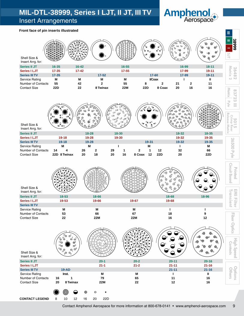
Front face of pin inserts illustrated
1
6
11
17
30
A
B
C
D
E
F
A
B
C
DE
F
G
H
A
D
C
B
AB
C
D
E
FGHJ
KL
M
N
P
RS T
U
V
WX
Y
Z
ab
c
MIL-DTL-38999, Series I LJT, II JT, III TV Insert Arrangements
A
B
C 12
3
45
61
2
345
67 A
B
51
64
3
21
23
4 A
BC
DC A
B
ABA
BC
D A
B
CD
E
F1
2
3
456
7
8
910
11
1213
12
3
456
7
8
910
11
1213
A
B
CD
E FA
B
CD
E
F
GA
B
C
A
B
C
D
AB
CD
E
FG
H 22
1
20
1
2122
AB
C
DE
F
G
H
JK
AB
CD
EA
BC
D
AB
C
DE
FG
H
J
KL
MN
P
R
A
B
C
D
EFG
H
J
KL
M N
P
RS
T U
AB
C
D
EFGH
J
K
LM
N P
R
ST
U V
1
2131A
BC
D
EFG
H
JK
L
M
1
11
2131
A
B
C
DE
F
GH
CONTACT LEGEND 8 10 12 16 20 22 22M 22D
A
BC
D
E
Shell Size & Insert Arrg. for:
Series II JT 8-2 8-3 8-6 8-35 8-44 8-97 8-98Series I LJT 9-3 9-6 9-7 9-22 9-35 9-44 9-98Series III TV 9-5 9-35 9-94 9-98Service Rating M M Grounded M M I M M M M INumber of Contacts 2 3 1 6 7 2 6 4 2 2 2 3Contact Size 20 20 8 Twinax 22M 22M 20 22D 22 20 22M 20 20
AB
Shell Size & Insert Arrg. for:
Series II JT 10-4 10-5 10-13 10-35 10-98 10-99 12-3Series I LJT 11-2 11-4 11-5 11-6 11-13 11-35 11-98 11-99 13-3Series III TV 11-2 11-4 11-5 11-35 11-54 11-98 11-99Service Rating I I I I M M II I I IINumber of Contacts 2 4 5 6 13 13 4 6 7 3Contact Size 16 20 20 20 22M 22D 22D 20 20 16
Shell Size & Insert Arrg. for:
Series II JT 12-4 12-8 12-22 12-35 12-98 14-4 14-5 14-15Series I LJT 13-4 13-8 13-22 13-35 13-98 15-4 15-5 15-15Series III TV 13-4 13-8 13-35 13-63 13-98 15-4 15-5 15-15Service Rating I I M M I I I II INumber of Contacts 4 8 22 22 2 2 10 4 5 14 1Contact Size 16 20 22M 22D 16 12 20 12 16 20 16
Shell Size & Insert Arrg. for:
Series II JT 14-18 14-19 14-35 14-37 14-68 14-97Series I LJT 15-18 15-19 15-35 15-37 15-68 15-97 17-2Series III TV 15-18 15-19 15-35 15-97 17-2Service Rating I I M M I I MNumber of Contacts 18 19 37 37 8 8 4 38 1Contact Size 20 20 22D 22M 16 20 16 22D 8 Twinax
Shell Size & Insert Arrg. for:
Series II JT 16-6 16-8 16-13 16-26Series I LJT 17-6 17-8 17-13 17-22 17-25 17-26Series III TV 17-6 17-8 17-22 17-26Service Rating I II I Coax M INumber of Contacts 6 8 13 2 2 22 2 26Contact Size 12 16 16 12 Coax 8 Coax 22D 8 Coax 20
A
B
D
C
AB
C
D
EF
G
H
J
K
LN M
12
3
4
56
789
10
1112
13 14
15 16
17
1819
20
2122
23
24
B A
AB
C
D
9
2648283723 III
501526500 Pyle
PrintedCircuit Board
EMI Filter
TransientFiber O
pticsO
ptions O
thersM
atrix Pyle
Crim
p Rear Release M
atrixM
atrix 2 H
igh SpeedContacts
38999
I II
IIISJT
Contact Amphenol Aerospace for more information at 800-678-0141 • www.amphenol-aerospace.com
AmphenolAerospace
CONTACT LEGEND
Front face of pin inserts illustrated
1
3
4
9
10
16
17
24
25
31
32
39
40
47
46
52
53
55
AB
C
D
E
FGHJ
KL
M
N
P
R
S TU
VWX
YZ
A
B
C
D
E
F
G
H
J
K
L
A
B
C
D
EF
G
H
J
K
L
M
N
PR
S
8 10 12 16 20 22D
MIL-DTL-38999, Series I LJT, II JT, III TV Insert Arrangements
Shell Size & Insert Arrg. for:
Series II JT 16-35 16-42 16-55 16-99 18-11Series I LJT 17-35 17-42 17-55 17-99 19-11Series III TV 17-35 17-52 17-60 17-99 19-11Service Rating M M M M I/Coax I IINumber of Contacts 55 42 2 55 8 2 21 2 11Contact Size 22D 22 8 Twinax 22M 22D 8 Coax 20 16 16
Shell Size & Insert Arrg. for:
Series II JT 18-28 18-30 18-32 18-35Series I LJT 19-18 19-28 19-30 19-32 19-35Series III TV 19-18 19-28 19-31 19-32 19-35Service Rating M M I M I MNumber of Contacts 14 4 26 2 29 1 2 1 12 32 66Contact Size 22D 8 Twinax 20 18 20 16 8 Coax 12 22D 20 22D
Shell Size & Insert Arrg. for:
Series II JT 18-53 18-66 18-68 18-96Series I LJT 19-53 19-66 19-67 19-68Series III TVService Rating M M M I INumber of Contacts 53 66 67 18 9Contact Size 22 22M 22M 16 12
1
21
31
41
51
6171
79
11
1
31
21
11
41
51
61
65
Shell Size & Insert Arrg. for:
Series II JT 20-1 20-2 20-11 20-16Series I LJT 21-1 21-2 21-11 21-16Series III TV 19-AD 21-11 21-16Service Rating Inst. M M I IINumber of Contacts 16 1 79 65 11 16Contact Size 20 8 Twinax 22M 22 12 16
A
B
C
D
E
F
G
H
J
K
L
AB
C
D
E
FG
H
R
JK
LM
N
P
ST
UV
W
X
Y
Za
b
c
d
e
A
BC
EK
M
N
R
S
U
VW
gh
f AB
C
D
E
F
GH
JK
L
M
N
P
R
ST
UV
W
X
YZa
bc
d
ef
gh
j1
2
3
4
9
10
16
17
24
25
33
34
42
43
50
51
57
58
63
64
66
A
B
C
DE
F
G
H
J
K
L
M
N
P
R
S
T
U
AB
C
D
E
FG
HJKL
M
N
PR
S
TU
V
W
XY
Za
b
cd
e
g f
1
3
4
9
10
16
17
24
25
34
35
43
44
51
52
58
59
64
65
67
ABL
CK
DJ
EH
FGR
U
M
T N
S P
A
BH
C
DF
E
G J
1
41
515253
3111
21
1
2
3
4
9
10
2416
1725
33
34
42
43
50
51
57
58
63
64
66
1
21
42
41
31
11
1
3
4
9
10
16
17
2431
2532
39
40
46
47
52
53
55
A
B
1
5
28
9 310
7
6 4
1215 314
13
12
4
5
11 8
710
16
89
A
10
3899
9
2648
283
723
III50
1526
500
Pyle
Prin
ted
Circ
uit B
oard
EMI F
ilter
Tran
sien
tFi
ber O
ptic
sO
ptio
ns
Oth
ers
Mat
rix 2
M
atrix
Py
le
Crim
p Re
ar
Rele
ase
Mat
rixI
II
III
Hig
h Sp
eed
Cont
acts
SJT
Contact Amphenol Aerospace for more information at 800-678-0141 • www.amphenol-aerospace.com
AmphenolAerospace
1 2
3
45
6
7
8
91011
1213
14
15
16
17
1819
20
2122
24
23
25
2627
1
11
21
31
41
51
6171
79
CONTACT LEGEND
Front face of pin inserts illustrated
AB
C
D
E
F
GH
JKLM
NP
R
S
TU
V W
XY
Z
a
bc
de
f
gh
ij
k
mn
p
qr
AB
C
D
E
F
G
HJ
KLMN
P
R
S
T
UV
W
XY
Z
a
bc
def
g
h
i
jk
m
npq
r
s
tA
BC
D
AB
C
D
E
FG
H
J
KL
M
N
P
RS
T
U V
A
B
CD
EF
A
BK
CJ LP
MN
DH
EG
F
A
B
C
D
E
FG
HJ
K
L
M P
R
S
N
TU
V
W
X
AB
C
D
EF
GH
J
K
L
MN
P R
S
T
U
VWX
Y
Z
a
b
c
d
ef
g
h
j
8 10 12 16 20 22D
MIL-DTL-38999, Series I LJT, II JT, III TV Insert Arrangements
Shell Size & Insert Arrg. for:
Series II JT 20-35Series I LJT 21-25 21-27 21-35Series III TV 21-29 21-35Service Rating I I I MNumber of Contacts 25 27 19 4 4 79Contact Size 20 20 20 16 12 22D
AB
C
D
E
F
GHJ
K
L
M
N
PR
S
T
UV
W
XY
Za
b
AB
C
D
E
F
GHJ
K
L
M
N
PR
S
T
U
VW
X
Y
Z
a
b
cd
Shell Size & Insert Arrg. for:
Series II JT 20-39 20-41 22-1Series I LJT 21-39 21-41 21-75 21-79 23-1Series III TV 21-39 21-41 21-75 21-79Service Rating I I N II MNumber of Contacts 37 2 41 4 17 (See Note) 100Contact Size 20 16 20 (See Note) 22D 22M
Shell Size & Insert Arrg. for:
Series II JT 22-2 22-14 22-21 22-32Series I LJT 23-2 23-6 23-14 23-21 23-32Series III TV 23-6 23-14 23-21Service Rating M M I II INumber of Contacts 85 6 14 21 32Contact Size 22 8 Twinax 12 16 20
1
2
3
45
6
7
8
15
16
24
25
34
35
45
46
55
56
66
67
76
77
85
86
93
94
95
9697
98
99
100
1
4
5
11
12
19
20
28
29
38
39
47
48
57
58
66
67
74
75
81
82
85
Note: MS connector 21-75 is supplied with four size 8 twinax contacts. Commercial connector 21-75 is supplied with four size 8 coax contacts.MS connector 21-79 has provision for two size 8 coax contacts. Coax contacts are not supplied unless specified by customers.
11
2648283723 III
501526500 Pyle
PrintedCircuit Board
EMI Filter
TransientFiber O
pticsO
ptions O
thersM
atrix Pyle
Crim
p Rear Release M
atrixM
atrix 2 H
igh SpeedContacts
38999
I II
IIISJT
Contact Amphenol Aerospace for more information at 800-678-0141 • www.amphenol-aerospace.com
AmphenolAerospace
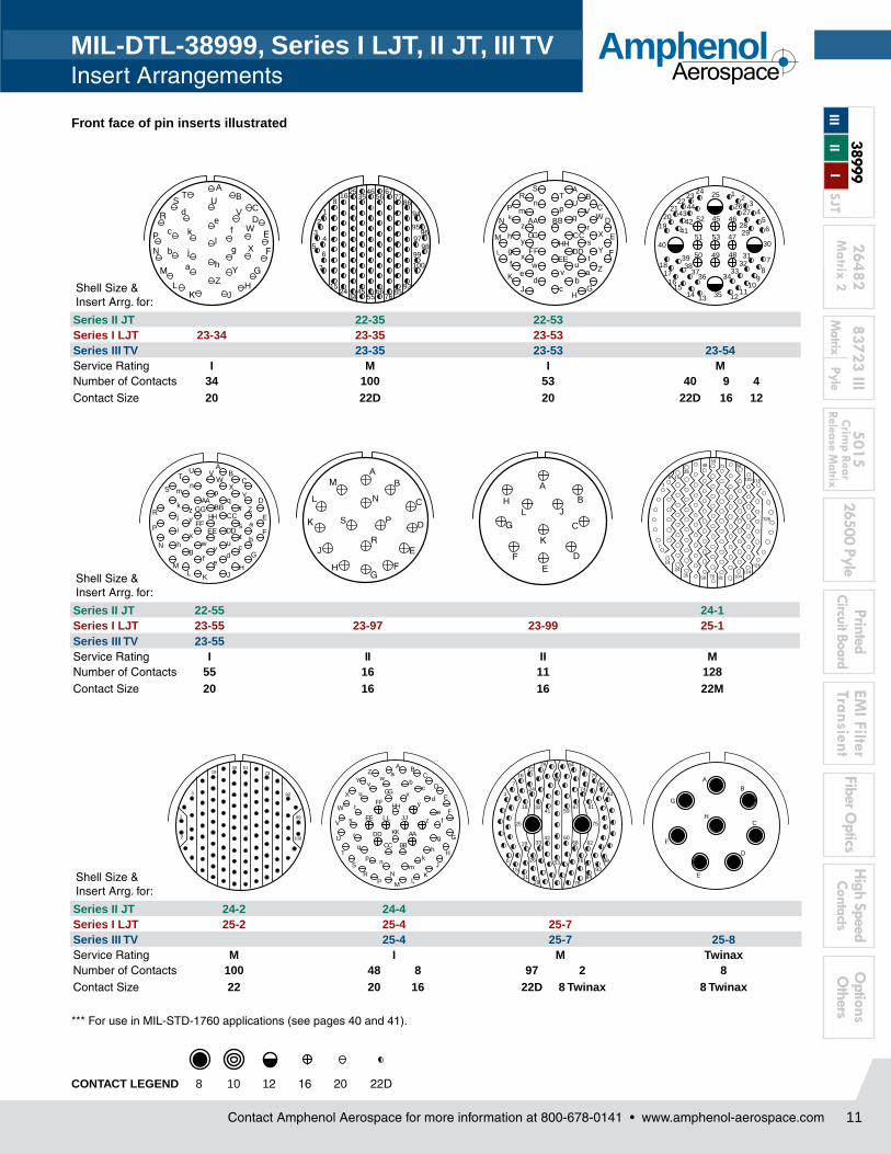
Front face of pin inserts illustrated
CONTACT LEGEND
*** For use in MIL-STD-1760 applications (see pages 40 and 41).
A BC
D
E
F
G
H
J
KL
M
NP
RS
T
U
V
W
X
YZ a
bc
d
ef
g
hk
mn
p
q
r
t
u
vw
x
y
zs JJ
KK
LL
AA
BBCC
DD
EE
FF
GG
HH
1
6
7
15
16
18
19
21
22
24
26
28
29
32
33
41
42
46
53
59
60
64
67
68
72
74
76
78
79
81
82
84
85
93
94
99
25 75
AB
C
D
E
F
G
H
8 10 12 16 20 22D
Shell Size & Insert Arrg. for:
Series II JT 22-35 22-53Series I LJT 23-34 23-35 23-53Series III TV 23-35 23-53 23-54Service Rating I M I MNumber of Contacts 34 100 53 40 9 4Contact Size 20 22D 20 22D 16 12
Shell Size & Insert Arrg. for:
Series II JT 22-55 24-1Series I LJT 23-55 23-97 23-99 25-1Series III TV 23-55Service Rating I II II MNumber of Contacts 55 16 11 128Contact Size 20 16 16 22M
AB
C
D
E
F
GH
J
K
L
M
N
P
RS
TU
VW
X
Y
Zab
cd
ef
g
h
km
np
qr
s
t
A B
uv
wx
y
zA B
CC
DDEE
FF
GGHH
1 23
456
7
89
1011
12131415
1617
18
1920
2122
2324 25
2627
2829
30
3132
3334
35
3637
3839
40
4142
4344
45 46
47
484950
51
52
53
AB
C
D
E
F
G
HJKL
M
N
P
R
S
TU V
WX
Y
Z
a
bc
def
gh
i
j
k
mn
pq
r
s
t
vw
x
yz
AABB
CC
u
DDEEFF
GGHH
Shell Size & Insert Arrg. for:
Series II JT 24-2 24-4Series I LJT 25-2 25-4 25-7Series III TV 25-4 25-7 25-8Service Rating M I M TwinaxNumber of Contacts 100 48 8 97 2 8Contact Size 22 20 16 22D 8 Twinax 8 Twinax
AB
CD
E
F
G
HJK
L
M
N
P
R
ST
UV
W
X
YZ
a
b
c
de
f
g
hj
kl
12
34
56
7
8
15
16
24
25
34
35
45
46
55
56
66
67
76
77
85
86
93
94
9596
9798
99
100
AB
C
D
E
FG
H
J
K
L
M
N
P
R
S
A
B
C
DE
F
G
HJ
K
L
1
7
8
14
24
2548
58
59
70
71
81
94
104
105
114
115
121
125
35
15
1
2
3
1940 51
73
92
99
100
MIL-DTL-38999, Series I LJT, II JT, III TV Insert Arrangements
3899
9
2648
283
723
III50
1526
500
Pyle
Prin
ted
Circ
uit B
oard
EMI F
ilter
Tran
sien
tFi
ber O
ptic
sO
ptio
ns
Oth
ers
Mat
rix 2
M
atrix
Py
le
Crim
p Re
ar
Rele
ase
Mat
rixI
II
III
Hig
h Sp
eed
Cont
acts
SJT
Contact Amphenol Aerospace for more information at 800-678-0141 • www.amphenol-aerospace.com
AmphenolAerospace
Contact Amphenol Aerospace for more information at 800-678-0141 • www.amphenol-aerospace.com
AmphenolAerospace
12
A
B
C
D
EF
G
HJ
KL
A B
C
D
E
F
G
H
JKL
M
N
P
R
S
T
U
V
W
XY
Z
ab
cd
e
f
gh
km
np
q r st
uv
w
A B
C
D
E
FGH
J
K
L
M
N P
R
ST
U V
A B
C
D
E
F
G
H
J
K
L
M
N
P
R
S
T
U
VWX
Y
Z
1
23
4
5
67
AB
C
D
E
F
GH
JK
L
M
N
P
RS
T
U
VW
X
Y Z
a
1
2
3
4
5
6
78
9
10
11
12
13
14
15
1617
18 19 20
21
222324
25
Front face of pin inserts illustrated
CONTACT LEGEND
† Coax contacts for RG180/U or RG195/U cable.
AB
C
D
E
F
GHJ
K
L
M
N
P
RS T
U
V
W
XY
Z
a
b c
d
e
f
1
4
7
8
14
15
24
25
35
36
47
48
58
59
70
71
81
82
93
94
104
105
114
115
121
125
128
AB
C
D
E
F
G
H
JKL
M
N
P
R
S
T
U
V
W
XY
Za
b
cd
e
fgh
k
mn
p
qr
s
tu
v
w
xy
z
AA
8 10 12 16 20 22D
Shell Size & Insert Arrg. for:
Series II JT 24-19Series I LJT 25-11 25-19 25-20Series III TV 25-11*** 25-17 25-19 25-20***Service Rating N M I NNumber of Contacts 2 9 36 6 19 10 13 3 4Contact Size 20 10 22D 8 Twinax 12 20 16 8 Twinax 12 Coax
Shell Size & Insert Arrg. for:
Series II JT 24-24 24-29 24-35Series I LJT 25-24 25-29 25-35Series III TV 25-24 25-26 25-29 25-35Service Rating I I I MNumber of Contacts 12 12 16 5 4 29 128Contact Size 16 12 20 12 8 Coax 16 22D
Shell Size & Insert Arrg. for:
Series II JT 24-37 25-43Series I LJT 25-37 25-43 25-46Series III TV 25-37 25-43 25-46Service Rating I I INumber of Contacts 37 23 20
1640 4 2
Contact Size 16 20 20 16 8 Coax
(With Matched Impedance)
A B
C
D
E
F
G
HJ
K
LM
N
P
R
S
T
U
VW
X
Y
Z
ab
c
d
e
fg
hk
m
np
qr
A BC
D
E
F
G
H
JK
LMNP
R
S
T
U
V
W
XY
Za
b
c
d
ef
g
h
k
m
n p
q
r
stu
v
w
x
MIL-DTL-38999, Series I LJT, II JT, III TV Insert Arrangements
2648283723 III
501526500 Pyle
PrintedCircuit Board
EMI Filter
TransientFiber O
pticsO
ptions O
thersM
atrix Pyle
Crim
p Rear Release M
atrixM
atrix 2 H
igh SpeedContacts
38999
I II
IIISJT
Contact Amphenol Aerospace for more information at 800-678-0141 • www.amphenol-aerospace.com
AmphenolAerospace
Contact Amphenol Aerospace for more information at 800-678-0141 • www.amphenol-aerospace.com
AmphenolAerospace
15Contact Amphenol Aerospace for more information at 800-678-0141 • www.amphenol-aerospace.com
AmphenolAerospace
15
MIL-DTL-38999, Series I LJT, II JT, III TVSpecifications/ Contacts
CONTACT RATING
*When tested using silver plated wire.
SERVICE RATING**
** Please note that the establishment of electrical safety factors is left entirely in the designer’s hands, since he is in the best position to know what peak voltage, switching surges, transients, etc. can be expected in a particular circuit.
8 .181 ± .002 .490 NA NA4 .281 ± .002 .490 NA NA0 .453 ± .002 .585 NA NA
MIL-DTL-38999 Series II JT/ Series I LJT CRIMP CONTACTSContact Size JT/LJT Pins
MS No.JT Socket
MS No.LJT Sockets
MS No.8 (Coax)* M39029/60-367 NA M39029/59-3668 (Twinax) M39029/90-529** NA M39029/91-53010 (Power) M39029/58-528 NA M39029/56-52712 M39029/58-365 M39029/57-359 M39029/56-35316 M39029/58-364 M39029/57-358 M39029/56-352
MIL-DTL-38999 Series III STANDARD 500 CYCLE CONTACTS FOR TV AND CTV, P & S
MIL-DTL-38999 Series III 1500 CYCLE CONTACTS FOR CTV, CLASSES H & J
Above part numbers include standard 500 cycle finish designation - gold plating over suitable underplate in accordance with SAE AS39029. For other finish variations, consult Sidney, NY. *For use with RG180B/U and RG195A/U cable. For other size 8 coax or optional sizes 12 and 16 coax contacts available for use in Tri-Start connectors, see High Speed Contact section of this catalog or consult Amphenol, Sidney, NY.
** For use with M17/M176-00002 cable. † Optional design - see slash sheet MS39029.For other contact options available for use in Tri-Start connectors, (wire wrap, thermocouple, fiber optic) consult Amphenol. Wire wrap data given on next page.
Contact Size CTV Pins CTV SocketsCommercial No. Military No. Supersedes Commercial No. Military No. Supersedes
MIL-DTL-38999, Series I LJT, II JT, III TVSpecifications
FINISH DATA MIL-DTL-38999, Tri-Start Series III TV
Aluminum Shell Components Non-Hermetic
Finish Service Class
Military Commercial
Anodic Coating (Non-Conductive) C RX**
Electroless NickelF (Metal)
RFM (Composite)
Olive Drab Cadmium Plate Nickel BaseW (Metal)
RWJ (Composite)
Stainless Steel with Nickel Plate S RS
Stainless Steel K RK
Durmalon plated T DT
Zinc-Nickel Plated Z ZN
Hermetic Shell Components
Material/Finish Service Class
Military Commercial
Stainless Steel Y Y
Stainless Steel with Nickel Plate N YN
**Add Suffix (005) to part number.
45
2648283723 III
501526500 Pyle
PrintedCircuit Board
EMI Filter
TransientFiber O
pticsO
ptions O
thersM
atrix Pyle
Crim
p Rear Release M
atrixM
atrix 2 H
igh SpeedContacts
38999
I II
IIISJT
Contact Amphenol Aerospace for more information at 800-678-0141 • www.amphenol-aerospace.com
AmphenolAerospace
Step 6. Select an Alternate PositionA, B, C, D, E, blank for normal
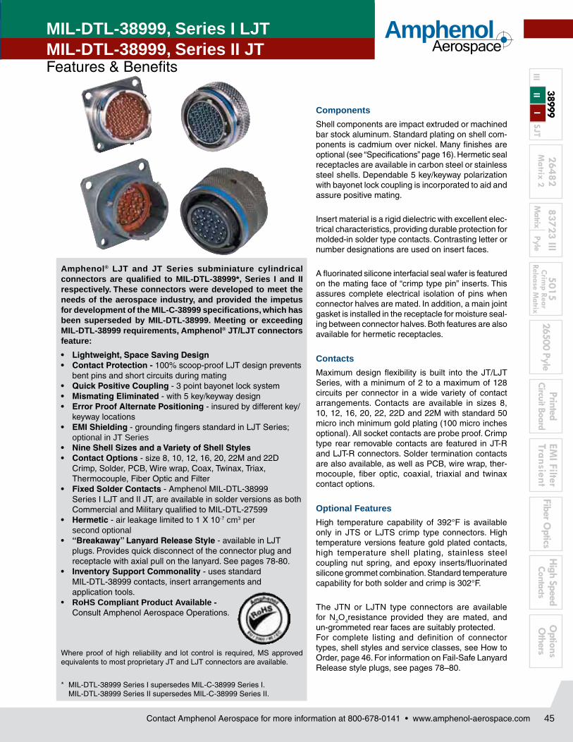
Amphenol® LJT and JT Series subminiature cylindrical connectors are qualified to MIL-DTL-38999*, Series I and II respectively. These con nectors were developed to meet the needs of the aerospace industry, and provided the impetus for development of the MIL-C-38999 specifications, which has been superseded by MIL-DTL-38999. Meeting or exceeding MIL-DTL-38999 requirements, Amphenol® JT/LJT connectors feature:
bent pins and short circuits dur ing mating• QuickPositiveCoupling - 3 point bayonet lock system• MismatingEliminated- with 5 key/keyway design• ErrorProofAlternatePositioning - insured by different key/
keyway locations• EMIShielding - grounding fingers standard in LJT Series;
optional in JT Series• NineShellSizesandaVarietyofShellStyles• ContactOptions - size 8, 10, 12, 16, 20, 22M and 22D
Crimp, Solder, PCB, Wire wrap, Coax, Twinax, Triax, Thermocouple, Fiber Optic and Fil ter
• FixedSolderContacts - Amphenol MIL-DTL-38999 Series I LJT and II JT, are available in solder versions as both Commercial and Military qualified to MIL-DTL-27599
• Hermetic- air leakage limited to 1 X 10⁻⁷ cm3 per second optional
• “Breakaway”LanyardReleaseStyle- available in LJT plugs. Provides quick disconnect of the connector plug and receptacle with axial pull on the lanyard. See pages 78-80.
• InventorySupportCommonality - uses stan dard MIL-DTL-38999 contacts, insert arrangements and application tools.
• RoHS Compliant Product Available - Consult Amphenol Aerospace Operations.
Where proof of high reliability and lot control is required, MS approved equivalents to most propri etary JT and LJT connectors are available.
* MIL-DTL-38999 Series I supersedes MIL-C-38999 Series I. MIL-DTL-38999 Series II supersedes MIL-C-38999 Series II.
MIL-DTL-38999, Series I LJT MIL-DTL-38999, Series II JT Features & Benefits
Components
Shell components are impact extruded or machined bar stock aluminum. Standard plating on shell com-ponents is cadmium over nickel. Many finishes are optional (see “Specifications” page 16). Hermetic seal receptacles are available in carbon steel or stainless steel shells. Dependable 5 key/keyway polarization with bayonet lock coupling is incorpo rated to aid and assure positive mating.
Insert material is a rigid dielectric with excellent elec-trical characteristics, providing durable protec tion for molded-in solder type contacts. Contrasting letter or number designations are used on insert faces.
A fluorinated silicone interfacial seal wafer is fea tured on the mating face of “crimp type pin” inserts. This assures complete electrical isolation of pins when connector halves are mated. In addition, a main joint gasket is installed in the receptacle for moisture seal-ing between connector halves. Both features are also available for hermetic receptacles.
Contacts
Maximum design flexibility is built into the JT/LJT Series, with a minimum of 2 to a maximum of 128 circuits per connector in a wide variety of contact arrangements. Contacts are available in sizes 8, 10, 12, 16, 20, 22, 22D and 22M with standard 50 micro inch minimum gold plating (100 micro inches optional). All socket contacts are probe proof. Crimp type rear removable contacts are featured in JT-R and LJT-R connectors. Solder termination contacts are also available, as well as PCB, wire wrap, ther-mocouple, fiber optic, coaxial, triaxial and twinax contact options.
Optional Features
High temperature capability of 392°F is available only in JTS or LJTS crimp type connectors. High temperature versions feature gold plated contacts, high temperature shell plating, stainless steel cou pling nut spring, and epoxy inserts/fluorinated sili cone grommet combination. Standard temperature capability for both solder and crimp is 302°F.
The JTN or LJTN type connectors are available for N2O4resistance provided they are mated, and un-grommeted rear faces are suitably protected.For complete listing and definition of connector types, shell styles and service classes, see How to Order, page 46. For information on Fail-Safe Lanyard Release style plugs, see pages 78–80.
46
3899
9
2648
283
723
III50
1526
500
Pyle
Prin
ted
Circ
uit B
oard
EMI F
ilter
Tran
sien
tFi
ber O
ptic
sO
ptio
ns
Oth
ers
Mat
rix 2
M
atrix
Py
le
Crim
p Re
ar
Rele
ase
Mat
rixI
II
III
Hig
h Sp
eed
Cont
acts
SJT
Contact Amphenol Aerospace for more information at 800-678-0141 • www.amphenol-aerospace.com
AmphenolAerospace
Connector Type Series I II
Shell Style Service Class Shell Size- Insert Arrangement
Lanyard Release Connector (See pages 78-80 for ordering)
Connector Type Shell Style Service ClassShell Size-Insert Arrg.
Contact TypeAlternate Position
Special Variations
00
1. 2. 3. 4. 5. 6. 7.
Wall Mounting Receptacle
Line Receptacle
Jam Nut Receptacle
Straight Plug
Solder Mounting Receptacle
Lanyard Release Plug
Wall Mounting Receptacle
Box Mounting Receptacle
Straight Plug
Jam Nut Receptacle
90° Plug
Solder Mounting Receptacle
Series I LJT Series II JT
MIL-DTL-38999, Series I LJT MIL-DTL-38999, Series II JT How to Order (Commercial)
*Grounding fingers standard on all LJT plugs
47
2648283723 III
501526500 Pyle
PrintedCircuit Board
EMI Filter
TransientFiber O
pticsO
ptions O
thersM
atrix Pyle
Crim
p Rear Release M
atrixM
atrix 2 H
igh SpeedContacts
38999
I II
IIISJT
Contact Amphenol Aerospace for more information at 800-678-0141 • www.amphenol-aerospace.com
AmphenolAerospace
MIL-DTL-38999, Series I LJT MIL-DTL-38999, Series II JT How to Order (Commercial)
Serie
s I L
JTSe
ries
II JT
Step 3. Select a Service Class
Commercial Solder Contacts/Connectors
P Potting applications: These connectors are supplied with a potting boot. All shells are designed with integral features to retain potting boots.
A General Applications
A (SR) Threaded rear design with strain relief†
C Pressurized applications
C (SR) Threaded rear design with strain relief.†
E Box mount and thru-bulkhead only with no backend threads.
H Hermetic applications- Fused compression glass sealed inserts. Leadage rate less than .01 micron cu. ft./hr. (1 x 10⁻⁷ cc/sec.) at 15 psi differential.
Y Same as “H” with interfacial seal.
T MS27599A applications-general duty, pressurized (receptacle only)
Commercial Crimp Contacts/Connectors
RP Potting crimp applications. Supplied with spacer grommet and potting boot.††
RE Environmental crimp applications. Supplied with a grommet and compression nut.† Can be supplied with strain relief integral with compression nut “RE(SR)”. (JT Series only)
RT Environmental applications. Supplied without rear accessories. Design provides serrations on rear threads of shells.
Connector Type
Shell Style Service Class
Shell Size-Insert Arrg.
Contact Type Alternate Position
Special Variations
RX
1. 2. 3. 4. 5. 6. 7.
Step 4. Select a Shell Size & Insert Arrangement see page 4-7
Connector Type
Shell Style Service Class Shell Size-Insert Arrg.
Contact Type Alternate Position
Special Variations
22-2
1. 2. 3. 4. 5. 6. 7.
Step 5. Select a Contact Type
Designates
P Pin Contacts
S Socket Contacts
Connector Type
Shell Style Service Class Shell Size- Insert Arrg.
Contact Type
Alternate Position
Special Variations
P
1. 2. 3. 4. 5. 6. 7.
MIL-DTL-38999, Series I LJT MIL-DTL-38999, Series II JT How to Order (Commercial)
Shell Size & Insert Arrangements are on pages 4-7. First number represents Shell Size, second number is the Insert Arrangement.
† Not applicable to box mounting style or LJT Series I. †† Not applicable to box mounting style.
48
3899
9
2648
283
723
III50
1526
500
Pyle
Prin
ted
Circ
uit B
oard
EMI F
ilter
Tran
sien
tFi
ber O
ptic
sO
ptio
ns
Oth
ers
Mat
rix 2
M
atrix
Py
le
Crim
p Re
ar
Rele
ase
Mat
rixI
II
III
Hig
h Sp
eed
Cont
acts
SJT
Contact Amphenol Aerospace for more information at 800-678-0141 • www.amphenol-aerospace.com
AmphenolAerospace
ROTATIONLETTERS
NORMAL
B A D C
AB
5˚ LJT REF
RELATIVE POSSIBLE POSITIONOF ROTATED MASTER KEYWAY (front face of receptacle shown)
ROTATIONLETTERS
NORMAL
B A D C
AB
10˚ JT REF
RELATIVE POSSIBLE POSITIONOF ROTATED MASTER KEYWAY (front face of receptacle shown)
“A” designates Alternate keying connector assembly. Other basic alternate keys are “B”, “C” and “D”. No letter required for normal rotation (no rotation) position.
A plug with a given rotation letter will mate with a receptacle with the same rotation letter. The AB angle for a given connec tor is the same whether it contains pins or sockets. Only the master key/keyway rotates in the shell, and the minor keys are fixed.
AB angles shown are viewed from the front face of the connec tor, a recep-tacle is shown below. The angles for the plug are exactly the same except the direction of rotation is opposite of that shown for the receptacle.
The “N” designation is not referenced in part number, it is omitted.
Step 6. Select an Alternate Keying Position
Connector Type Shell Style Service Class Shell Size Insert Arrg.
Contact Type Alternate Position
Special Variations
A
1. 2. 3. 4. 5. 6. 7.
Step 7. Select a Strain Relief Option or Finish Variation Suffix
Connector Type
Shell Style Service Class Shell Size- Insert Arrg.
Contact Type Alternate Position
Special Variations
( )
1. 2. 3. 4. 5. 6. 7.
Strain Relief Options: “SR” designates a strain relief clamp. Strain reliefs are available only on Service Class “A”, “C” and “RE” (see step 3. Service Class)
Finish Variation Suffix: See finish variations available in table to your right.
FinishMilitary
Finish DataFinish Suffix
Finish Plus “SR” Suffix
Cadmium plated nickel base 175° C A (SR)
Olive drab cadmium plate nickel base 175° C B (014) (386)
Electroless nickel 200° C F (023) (424)
Electroless nickel, space compatible 200° C
(453) (467)
Anodic coating (Alumilite) 200° C
C (005) (300)
Chromate treated (Iridite 14-2) 125° C
(011) (344)
Passivated steel 200° C E - -
Nickel-PTFE 175° C (038)
AB ANGLE OF ROTATION (Degrees)
Shell Size Normal A B C D
9 95° 77° - - 113°
11 95° 81° 67° 123° 109°
13 95° 75° 63° 127° 115°
15 95° 74° 61° 129° 116°
17 95° 77° 65° 125° 113°
19 95° 77° 65° 125° 113°
21 95° 77° 65° 125° 113°
23 95° 80° 69° 121° 110°
25 95° 80° 69° 121° 110°
LJT Key/Keyway Rotation
AB ANGLE OF ROTATION (Degrees)
Shell Size Normal A B C D
8 100° 82° - - 118°
10 100° 86° 72° 128° 114°
12 100° 80° 68° 132° 120°
14 100° 79° 66° 134° 121°
16 100° 82° 70° 130° 118°
18 100° 82° 70° 130° 118°
20 100° 82° 70° 130° 118°
22 100° 85° 74° 126° 115°
24 100° 85° 74° 126° 115°
JT Key/Keyway Rotation
MIL-DTL-38999, Series I LJT MIL-DTL-38999, Series II JTHow to Order (Commercial)
49
2648283723 III
501526500 Pyle
PrintedCircuit Board
EMI Filter
TransientFiber O
pticsO
ptions O
thersM
atrix Pyle
Crim
p Rear Release M
atrixM
atrix 2 H
igh SpeedContacts
38999
I II
IIISJT
Contact Amphenol Aerospace for more information at 800-678-0141 • www.amphenol-aerospace.com
AmphenolAerospace
MIL-DTL-38999, Series I LJT MIL-DTL-38999, Series II JTHow to Order (Commercial)
Designates
MS27472 Crimp Wall Mount Receptacle
MS27497 Crimp Wall Mount Receptacle Back Panel Mounting
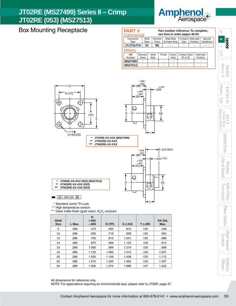
MS27499 Crimp Box Mounting Receptacle
MS27513 Crimp Box Mounting Receptacle with grommet and compression nut
MS Number Service Class Shell Size Finish Insert Arrangement
Contact Style (P or S)
Alternate Keying Position
MS27473 E 14 A 18 P A
Easy Steps to build a Military part number... Series I and II
1. 2. 3. 4. 5. 6. 7.
Step 1. Choose your Military Connector Type
Military
1. 2. 3. 4. 5. 6. 7.MS Number Service Class Shell Size Finish Insert
ArrangementContact Style
(P or S)Alternate Position
MS27473
Series II JT Series I LJT
Step 2. Select a Military Service Class
Military Service Class
E Environmental crimp applications. Supplied with a grommet and compression nut.† Can be supplied with strain relief integral with compression nut “RE(SR)”. (JT Series only). Box Mount versions using spacer grommets are not environmental.
P Potting crimp applications. Supplied with spacer grommet and potting boot.††
T Environmental applications. Supplied without rear accessories. Design provides serrations on rear threads of shells. (MS27599 applications)- General duty-pressurized (receptacles only)
Y Hermetically interfacial seal
1. 2. 3. 4. 5. 6. 7.MS Number Service
ClassShell Size Finish Insert
ArrangementContact Style
(P or S)Alternate Position
E
MIL-DTL-38999, Series I LJT MIL-DTL-38999, Series II JTHow to Order (Commercial)
† Not applicable to box mounting style or LJT Series I. †† Not applicable to box mounting style.
3899
9
2648
283
723
III50
1526
500
Pyle
Prin
ted
Circ
uit B
oard
EMI F
ilter
Tran
sien
tFi
ber O
ptic
sO
ptio
ns
Oth
ers
Mat
rix 2
M
atrix
Py
le
Crim
p Re
ar
Rele
ase
Mat
rixI
II
III
Hig
h Sp
eed
Cont
acts
SJT
Contact Amphenol Aerospace for more information at 800-678-0141 • www.amphenol-aerospace.com
AmphenolAerospace
Contact Amphenol Aerospace for more information at 800-678-0141 • www.amphenol-aerospace.com
AmphenolAerospace
50
FinishMilitary
Finish DataFinish Suffix
Finish Plus “SR” Suffix
Cadmium plated nickel base 175° C
A (SR)
Olive drab cadmium plate nickel base 175° C
B (014) (386)
Electroless nickel 200° C F (023) (424)Electroless nickel, space compatible 200° C
(453) (467)
Anodic coating (Alumilite) 200° C
C (005) (300)
Chromate treated (Iridite 14-2) 125° C
(011) (344)
Passivated steel 200° C E - -
Nickel-PTFE 175° C (038)
Step 3 & 5. Select a Shell Size and Insert Arrangement from Pages 4-7
1. 2. 3. 4. 5. 6. 7.MS Number Service Class Shell Size 4. Finish Insert
ArrangementContact Style
(P or S)Alternate Position
14 18
Shell Size & Insert Arrangement are on pages 4-7. First number represents Shell Size, second number is the Insert Arrangement. Place Shell Size in box 3 and Insert Arrangement in box 5.
Step 4. Select a Military Finish
1. 2. 3. 4. 5. 6. 7.MS Number Service Class Shell Size Finish Insert
ArrangementContact Style
(P or S)Alternate Position
A
Step 6. Select a Military Contact Type
Designates
P Pin Contacts
S Socket Contacts
1. 2. 3. 4. 5. 6. 7.MS Number Service Class Shell Size Finish Insert
ArrangementContact Style
(P or S)Alternate Position
P
Step 7. Select an Alternate Keying PositionSee pg 48 for information, No letter required for normal position
1. 2. 3. 4. 5. 6. 7.MS Number Service Class Shell Size Finish Insert
ArrangementContact Style
(P or S) Alternate Position
A
MIL-DTL-38999, Series I LJT MIL-DTL-38999, Series II JTHow to Order (Military)
Contact Amphenol Aerospace for more information at 800-678-0141 • www.amphenol-aerospace.com 51
AmphenolAerospace
Contact Amphenol Aerospace for more information at 800-678-0141 • www.amphenol-aerospace.com 51
AmphenolMIL-DTL-38999, Series II, JT
TABLE OF CONTENTSCombined MIL-DTL-38999 Series I, II, III
* Standard Junior Tri-Lock ** High temperature version *** Clear iridite finish (gold color), N2O4 resistant ****Dimensions L and X1 are applicable when the end of the screw is flush with the surface BB.
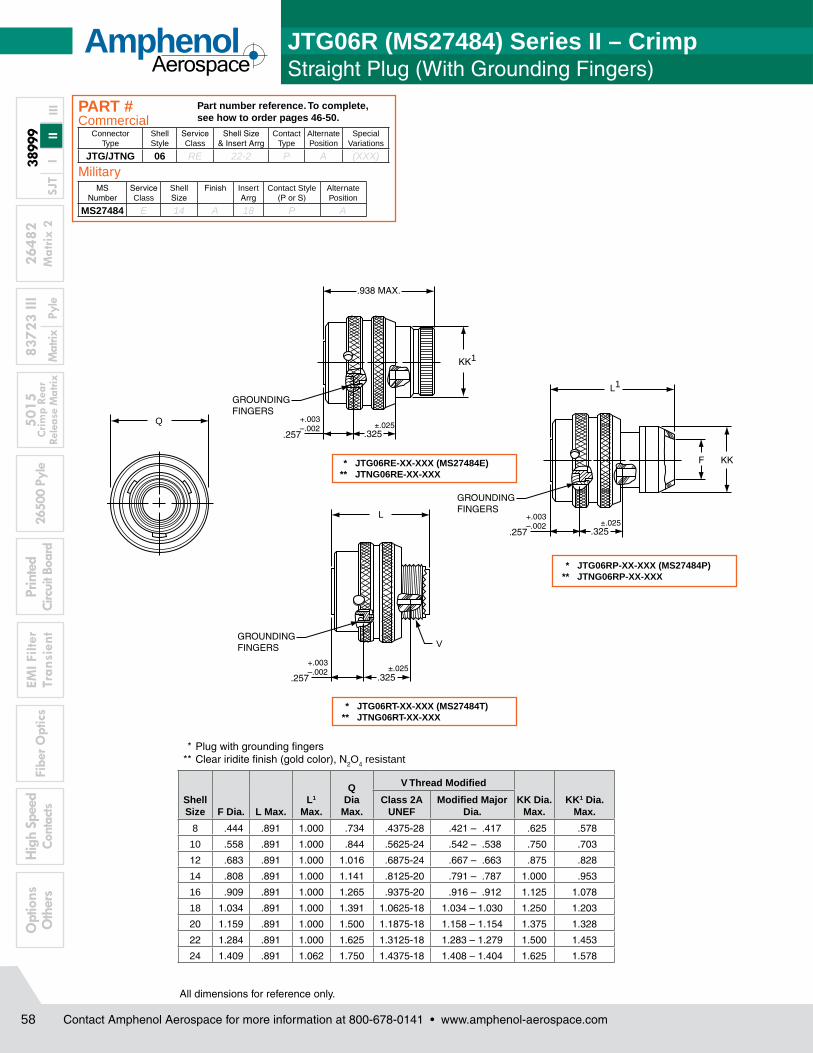
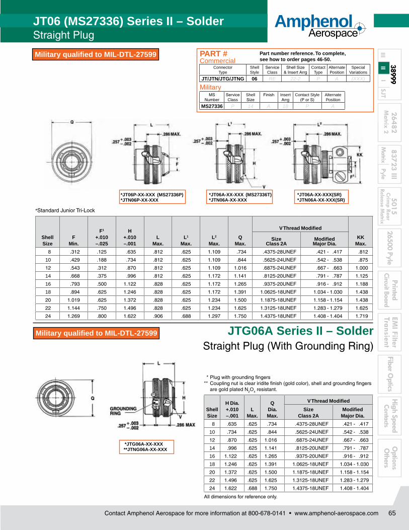
JTG06A Series II – Solder Straight Plug (With Grounding Ring)
*JT06P-XX-XXX (MS27336P)*JTN06P-XX-XXX
*JT06A-XX-XXX (MS27336T)*JTN06A-XX-XXX
*JT06A-XX-XXX(SR)*JTN06A-XX-XXX(SR)
* Plug with grounding fingers** Coupling nut is clear iridite finish (gold color), shell and grounding fingers
are gold plated N2O4 resistant.
Shell Size
H Dia. +.010 –.001
L Max.
Q Dia. Max.
V Thread Modified
Size Class 2A
Modified Major Dia.
8 .635 .625 .734 .4375-28UNEF .421 - .417
10 .734 .625 .844 .5625-24UNEF .542 - .538
12 .870 .625 1.016 .6875-24UNEF .667 - .663
14 .996 .625 1.141 .8125-20UNEF .791 - .787
16 1.122 .625 1.265 .9375-20UNEF .916 - .912
18 1.246 .625 1.391 1.0625-18UNEF 1.034 - 1.030
20 1.372 .625 1.500 1.1875-18UNEF 1.158 - 1.154
22 1.496 .625 1.625 1.3125-18UNEF 1.283 - 1.279
24 1.622 .688 1.750 1.4375-18UNEF 1.408 - 1.404
All dimensions for reference only.
*JTG06A-XX-XXX **JTNG06A-XX-XXX
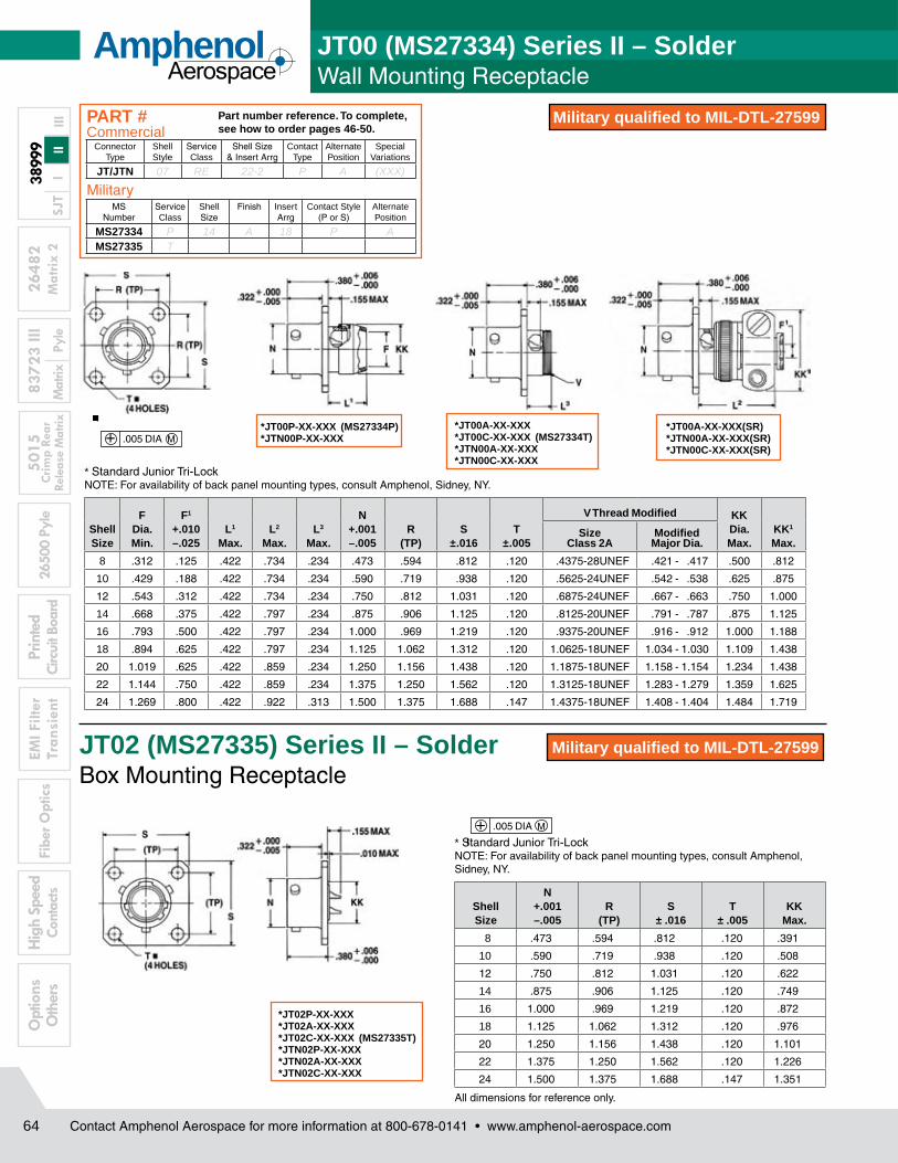
JT06 (MS27336) Series II – SolderStraight Plug
Military qualified to MIL-DTL-27599
Military qualified to MIL-DTL-27599
ConnectorType
Shell Style
Service Class
Shell Size& Insert Arrg
Contact Type
Alternate Position
Special Variations
JT/JTN/JTG/JTNG 06 RE 22-2 P A (XXX)
Part number reference. To complete, see how to order pages 46-50.
PART #
MS Number
Service Class
Shell Size
Finish Insert Arrg
Contact Style (P or S)
Alternate Position
MS27336 P 14 A 18 P A
Military
Commercial
Contact Amphenol Aerospace for more information at 800-678-0141 • www.amphenol-aerospace.com
AmphenolAerospace
66
3899
9
2648
283
723
III50
1526
500
Pyle
Prin
ted
Circ
uit B
oard
EMI F
ilter
Tran
sien
tFi
ber O
ptic
sO
ptio
ns
Oth
ers
Mat
rix 2
M
atrix
Py
le
Crim
p Re
ar
Rele
ase
Mat
rixI
II
III
Hig
h Sp
eed
Cont
acts
SJT
★ .059 dia. min. 3 lockwire holes• “D” shaped mounting hole dimensions. * Standard Junior Tri-Lock ** Panel thickness † O Ring not furnished with MS27337
JT07 (MS27337) Series II – Solder Jam Mounting Receptacle
Military qualified to MIL-DTL-27599
Military qualified to MIL-DTL-27599
ConnectorType
Shell Style
Service Class
Shell Size& Insert Arrg
Contact Type
Alternate Position
Special Variations
JT/JTN P RE 22-2 P A (XXX)
Part number reference. To complete, see how to order pages 46-50.
PART #Commercial
Contact Amphenol Aerospace for more information at 800-678-0141 • www.amphenol-aerospace.com
AmphenolAerospace
3
2648283723 III
501526500 Pyle
PrintedCircuit Board
EMI Filter
TransientFiber O
pticsO
ptions O
thersM
atrix Pyle
Crimp Rear
Release Matrix
Matrix 2
High SpeedContacts
38999
I II
IIISJT
Amphenol AerospaceNew, Featured Products
New/Featured
Filter Connector withHigh Density Patterns Page 289New High Density Patterns are available in Filter 38999 connec-tors in standard Mil-Spec or filter length shells. They provide 30% more contact that standard insert arrangement patterns. See page 43 for ordering information.
Breakaway Hybrid, Low Profile Lanyard Release Plug Page 42New Hybrid Lanyard Breakaway Fail Safe Connector with a composite thermoplastic outer operating sleeve for greater durability.
New HD38999 (High Density, Crimp) Plugs and receptacles Page 43, 44The HD38999 family of connectors was designed to work with existing Mil-specified 38999 shells. The HD38999 has 30% more contacts, it still performs to minimum electrical requirements of standard 38999 connectors.
MT FerruleConnectors Page 359Amphenol offers a multi-channel circular connector with high density MT fiber optics. High fiber density in a relatively small circular connector package with all the advantages of the MIL-DTL-38999 series III connector.
ARINC 801Connectors Page 356Designed for use in Amphenol ARINC 801 fiber optic connectors - manufactured to comply with ARINC 801. Genderless terminus allows for use on both sides of a connector.
Matrix MIL-DTL-5015with RADSOK® Contacts Page 193A special design of the Matrix MIL-DTL-5015, Series II connectors has added high amperage with the RADSOK® contacts in the plug instead of standard rear release crimp contacts.
Solution: Navy F-18 program needed a break away plug that would have greater durability in weapons release application.
Solution: 30% more contact density in 38999 Series III Shells
Solution: Higher amperage capability in Matrix MIL-DTL-5015
Solution: Higher contact density and custom stand-off shell designs
Solution: Fiber Optic Termini & Connector that meet ARINC specifications
Solution: Higher Density Fiber Optics in MIL-DTL-38999
Amphenol has become the leader in interconnection products through its long history of engineering expertise for product solution solving. New and innovative solutions are under development every day within our highly skilled engineering departments who are teamed with marketing product managers and production specialists. They are always striving to meet new customer requirements in ever changing markets. The teams have a customer-driven approach to produce the end result: quality interconnect products that meet or exceed customer demands.
New/Featured
New/Featured New/Featured
New/Featured New/Featured
Contact Amphenol Aerospace for more information at 800-678-0141 • www.amphenol-aerospace.com
AmphenolAerospace
89
2648283723 III
501526500 Pyle
PrintedCircuit Board
EMI Filter
TransientFiber O
pticsO
ptions O
thersM
atrix Pyle
Crim
p Rear Release M
atrixM
atrix 2 H
igh SpeedContacts
38999
I II
IIISJT
MIL-DTL-38999 Series III TV Tri-Start • Backshells Accessories • Dummy Contacts • Wire Combs • Receptacle Protection Cap • Plug Protection Cap • Dummy Receptacle • Cable Clamps • Contacts-Printed Circuit Board Wire Wrap • Header Assembly
Application Tools
• Crimp Tools • Insertion Tools • Removal Tools
MIL-DTL-38999 Series III, II, I, and SJTAccessories, Contacts, and Tools
MIL-DTL-38999 Series I LJT • Receptacle Protection Cap • Plug Protection Cap • Dummy Receptacle • Cable Clamps • Contacts-Printed Circuit Board Wire Wrap • Header Assembly
Application Tools
• Crimp Tools • Insertion Tools • Removal Tools
MIL-DTL-38999 Series II JT • Receptacle Protection Cap • Plug Protection Cap • Strain Relief (Solder/Crimp Type) • Contacts-Printed Circuit Board Wire Wrap • Header Assembly
Application Tools
• Crimp Tools • Insertion Tools • Removal Tools
Amphenol Aerospace is the leader in Interconnect solutions and provides companies with a product portfolio of connectors, accessories, cable assemblies and system integration for most applications across various industries. With connectors conform-ing to Military, Aerospace and Industrial standards in US, Europe and Asia, Amphenol assumes the leadership in meeting the interconnect needs of these market segments.
Series III TV Series II JT Series I LJT SJT
SJT • Receptacle Protection Cap • Plug Protection Cap • Dummy Receptacle • Cable Clamps
Application Tools
• Crimp Tools • Insertion Tools • Removal Tools
Contact Amphenol Aerospace for more information at 800-678-0141 • www.amphenol-aerospace.com
AmphenolAerospace
96
3899
9
2648
283
723
III50
1526
500
Pyle
Prin
ted
Circ
uit B
oard
EMI F
ilter
Tran
sien
tFi
ber O
ptic
sO
ptio
ns
Oth
ers
Mat
rix 2
M
atrix
Py
le
Crim
p Re
ar
Rele
ase
Mat
rixI
II
III
Hig
h Sp
eed
Cont
acts
SJT
B
.812 MAX
AN
C
.167 DIA.
+.010–.005
N
.562 MAX
A1
For MS stamping identification, accessories must be ordered by MS part number. If ordered by 10- part number, they will be stamped with said number. * To complete order number, add shell size and suffix number. For example, shell size 10 with cadmium plate, nickel base would be 10-241853-107, MS27510A10C or MS27510A10A).
All dimensions for reference only.
* 10-547138-XXX (MS27510XXXC)
* 10-241853-XXX (MS27510XXXA)
MIL-DTL-38999, Series II JT Plug Protection Cap
Shell Size
A Dia. Max.
A1 Dia. Max.
B +.000 –.016
C Approx.
N Dia. +.001 –.005
8 .719 .703 .563 3.000 .473
10 .844 .828 .680 3.000 .590
12 1.000 .984 .859 3.500 .750
14 1.125 1.109 .984 3.500 .875
16 1.250 1.234 1.108 3.500 1.000
18 1.375 1.359 1.233 3.500 1.125
20 1.500 1.484 1.358 4.000 1.250
22 1.625 1.609 1.483 4.000 1.375
24 1.750 1.734 1.610 4.000 1.500
Finish10-Number
Suffix
MS Number Suffix with
chain
MS Number Suffix without
chain
Chromate treat -XX0
Anodic coating -XX5 CXXC CXXA
Cadmium Plate Nickel base -XX7 AXXC AXXA
Olive Drab, Cadmium, Nickel base -XX9 BXXC BXXA
Electroless Nickel -XXG FXXC FXXA
Series II JT
Contact Amphenol Aerospace for more information at 800-678-0141 • www.amphenol-aerospace.com
AmphenolAerospace
97
2648283723 III
501526500 Pyle
PrintedCircuit Board
EMI Filter
TransientFiber O
pticsO
ptions O
thersM
atrix Pyle
Crim
p Rear Release M
atrixM
atrix 2 H
igh SpeedContacts
38999
I II
IIISJT
A
.812 MAX
D
A
.167 DIA.
+.010–.005
A
.531 MAX
.781 MAX
C
C
* 10-241856-XXX (MS27511XXXA)
* 10-241800-XXX (MS27511XXXC)
* 10-241802-XXX
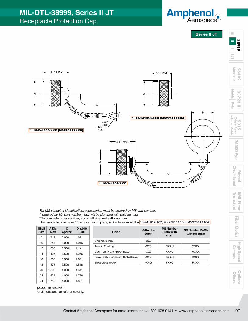
For MS stamping identification, accessories must be ordered by MS part number. If ordered by 10- part number, they will be stamped with said number. * To complete order number, add shell size and suffix number. For example, shell size 10 with cadmium plate, nickel base would be 10-241802-107, MS27511A10C, MS27511A10A
†3.000 for MS27511 All dimensions for reference only.
MIL-DTL-38999, Series II JTReceptacle Protection Cap
Shell Size
A Dia. Max.
C Approx.
D +.010 –.000
8 .719 3.000 .891
10 .844 3.000 1.016
12 1.000 3.500† 1.141
14 1.125 3.500 1.266
16 1.250 3.500 1.391
18 1.375 3.500 1.516
20 1.500 4.000 1.641
22 1.625 4.000 1.766
24 1.750 4.000 1.891
Finish10-Number
Suffix
MS Number Suffix with
chain
MS Number Suffix without chain
Chromate treat -XX0
Anodic Coating -XX5 CXXC CXXA
Cadmium Plate Nickel Base -XX7 AXXC AXXA
Olive Drab, Cadmium, Nickel base -XX9 BXXC BXXA
Electroless nickel -XXG FXXC FXXA
Series II JT
MIL-DTL-38999, Series II JT Plug Protection Cap
Contact Amphenol Aerospace for more information at 800-678-0141 • www.amphenol-aerospace.com
MIL-DTL-38999, Series II JT MIL-DTL-38999, Series I LJT Crimp/Thermocouple Contacts, Plastic Caps, Sealing Plugs
THERMOCOUPLE CONTACTS PYLE VERSION
Series II JT
Series I LJTContact Size
Pins (JT/LJT) MS No.
JT Sockets MS. No
LJT Sockets MS. No
8 (Coax)* M39029/60-367 NA M39029/59-366
8 (Twinax) M39029/90-529*** NA M39029/91-530
10 (Power) M39029/58-528 NA M39029/56-527
12 M39029/58-365 M39029/57-359 M39029/56-353
16 M39029/58-364 M39029/57-358 M39029/56-352
20 M39029/58-363 M39029/57-357 M39029/56-351
22 M39029/58-362 M39029/57-356 M39029/56-350
22M M39029/58-361 M39029/57-355 M39029/56-349
22D M39029/58-360 M39029/57-354 M39029/56-348
JT/LJT Crimp Contacts
Contact Amphenol Aerospace for more information at 800-678-0141 • www.amphenol-aerospace.com
AmphenolAerospace
106
3899
9
2648
283
723
III50
1526
500
Pyle
Prin
ted
Circ
uit B
oard
EMI F
ilter
Tran
sien
tFi
ber O
ptic
sO
ptio
ns
Oth
ers
Mat
rix 2
M
atrix
Py
le
Crim
p Re
ar
Rele
ase
Mat
rixI
II
III
Hig
h Sp
eed
Cont
acts
SJT Mounts to all MIL-DTL-38999 and
*MIL-DTL-26482 Connectors
Termination of PC tail connectors to a flex print or a printed circuit board represents a major cost in the manufacturing process for users. When adding flex or printed circuit board assemblies to an expensive filter or filter/transient protection connec-tor, the total cost of a failed solder joint, a bent pin, or an unanticipated electrical failure becomes prohibitive. The universal header assembly from Amphenol provides for easy separation of the connector from the board on these occasions. The header assembly is comprised of a short pin/socket contact. The tail end of the contact is soldered to the through hole of the flex or printed circuit board. The socket is embedded in the insulator, making electrical contact with the printed circuit tail of the connector.
Header Assemblies Provide Cost SavingsIncorporation of the header assembly provides the user with time and cost saving potentials. These header assemblies can be vapor phase or wave soldered to flex or printed circuit boards prior to the receipt of the EMI/EMP connector. Headers can be installed to standard connectors, allowing for electrical testing that would adversely affect the sensitive diodes, MOV’s or capacitors in the EMI/EMP connectors. Expensive connector assemblies can be easily removed from and reattached to the header assembly as the manufacturing process dictates.
Mounting ApplicationsShell modifications are recommended, but are not necessary. The header assembly can be attached to connectors with standard flange placement or directly to the circuit board. The ideal application would involve either a single flange moved all the way to the rear of the connector or a double flange. Cinch nuts can be installed in either flange to allow easier mounting to the panel or the header assembly. The forward flange would mount the connector to the panel; the rear flange would be used to mount the header assembly. Various types of captivated or loose attaching screws can be utilized for unique applications.Amphenol universal headers are slotted to allow mounting to all series of MIL-DTL-38999 or MIL-DTL-26482* connectors without special alterations. They are of similar dimension as the flange of the mounting connector and are approximately .185 inches (4.70 mm) thick.
* For information on Header Assemblies for MIL-DTL-26482 connector consult Amphenol, Sidney NY.
Cylindrical Configuration• 3 PCB stickout dimensions are available.• Size 22 contacts use .175 thick headers• Size 16 to 20 contacts use
.195 thick headers• Consult Amphenol, Sidney NY for
additional configurations.• Headers for cylindrical connectors accom-
modate up to 128 pins. For MIL-DTL-38999 insert arrangements chart see pages 4-7 and insert drawings on pages 8-14.
Mounting to Rectangular ARINC Connectors• Headers for ARINC connector arrangements
accommodate up to 150 pins• Consult Amphenol, Sidney, NY for ARINC
configurations and detailed dimensions.
Materials• Body is molded or machined from FR-4.• Electrical engagement areas of the header
contact are plated with .00003 inches minimum of gold over .00005 inches minimum of nickel.
See drawing of standard header on next page.
Headers provide easy separation of the connector from the PC board.
MIL-DTL-38999, Series III TV, II JT, I LJT Universal “Header Assembly”
for Flex Print or PC Board
Series III TV Series II JT Series I LJT
Contact Amphenol Aerospace for more information at 800-678-0141 • www.amphenol-aerospace.com
AmphenolAerospace
107
2648283723 III
501526500 Pyle
PrintedCircuit Board
EMI Filter
TransientFiber O
pticsO
ptions O
thersM
atrix Pyle
Crim
p Rear Release M
atrixM
atrix 2 H
igh SpeedContacts
38999
I II
IIISJT
R2
R1
S
T
TT
VISUALINDICATOR NOTCHFOR TOP C OFINSERT PATTERN(SIZE & CONFIGURATIONOPTIONAL)
L
F RADIUSBPCB STICKOUT(SEE SUFFIX CHART BELOW)
G
.020 ± .001
.040 ± .001 (SIZE 20)
.0625 ± .0010 (SIZE 16)
BPCB STICKOUT(SEE SUFFIX CHART BELOW)
.050
G
SIZE 22 CONTACT VIEW
SIZE 16 AND 20CONTACT VIEW
NOTE:Size 22 accepts .018 to .022 dia. PCB tails.Size 16 accepts .048 to .064 dia. PCB tails.Size 20 accepts .037 to .043 dia. PCB tails.
The drawing below shows the standard header assembly for use with MIL-DTL-38999 connectors. Consult Amphenol Aerospace, Sidney NY for drawings of headers for ARINC configurations.
ASSEMBLY NUMBER SUFFIX CHARTHOW TO ORDER INFORMATION For Header Assembly with MIL-DTL-38999 ConnectorsUse coded number as follows:
Designates Amphenol Header AssemblyShell size designation for MIL-DTL-38999 Series I, II, III and IV see Suffix chart.Arrangement number - See MIL-STD-1560 or MIL-STD-1669. See insert availability charts on pages 4-7.Contact PCB Stickout designation See Suffix chart.
For how to order information on adapters to be used with ARINC connectors, consult Amphenol, Sidney NY.
* Shell size designation for MIL-DTL-38999 Series I, II, III and IV and MIL-DTL-26482 Series 1 and 2. Examples: Shell size 9 use 08. Shell size 25 use 24.
** Size 22 contacts available in all 3 stickout lengths. Size 16 and 20 contacts available only in .185 and .270 lengths.
*** Insert arrangement 14-97 and 15-97 are not available at this time. Consult Amphenol, Sidney NY for information.
MIL-DTL-38999, Series III TV, II JT, I LJT Universal “Header Assembly” for Flex Print or PC Board Connectors
108 Contact Amphenol Aerospace for more information at 800-678-0141 • www.amphenol-aerospace.com
3899
9
2648
283
723
III50
1526
500
Pyle
Prin
ted
Circ
uit B
oard
EMI F
ilter
Tran
sien
tFi
ber O
ptic
sO
ptio
ns
Oth
ers
Mat
rix 2
M
atrix
Py
le
Crim
p Re
ar
Rele
ase
Mat
rixI
II
III
Hig
h Sp
eed
Cont
acts
SJT
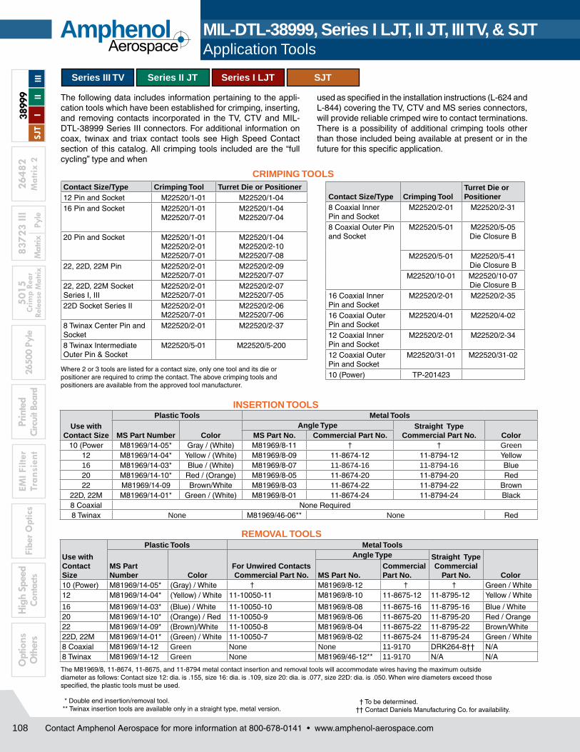
Where 2 or 3 tools are listed for a contact size, only one tool and its die or positioner are required to crimp the contact. The above crimping tools and positioners are available from the approved tool manufacturer.
The following data includes information pertaining to the appli-cation tools which have been established for crimping, inserting, and removing contacts incorporated in the TV, CTV and MIL-DTL-38999 Series III connectors. For additional information on coax, twinax and triax contact tools see High Speed Contact section of this catalog. All crimping tools included are the “full cycling” type and when
used as specified in the installation instructions (L-624 and L-844) covering the TV, CTV and MS series connectors, will pro vide reliable crimped wire to contact terminations. There is a possibility of additional crimping tools other than those included being available at present or in the future for this specific appli cation.
CRIMPING TOOLS
INSERTION TOOLS
REMOVAL TOOLS
The M81969/8, 11-8674, 11-8675, and 11-8794 metal contact insertion and removal tools will accommodate wires having the maximum outside diameter as follows: Contact size 12: dia. is .155, size 16: dia. is .109, size 20: dia. is .077, size 22D: dia. is .050. When wire diameters exceed those specified, the plastic tools must be used.
† To be determined.†† Contact Daniels Manufacturing Co. for availability.
* Double end insertion/removal tool. ** Twinax insertion tools are available only in a straight type, metal version.
MIL-DTL-38999, Series I LJT, II JT, III TV, & SJT Application Tools
Contact Size/Type Crimping Tool Turret Die or Positioner12 Pin and Socket M22520/1-01 M22520/1-0416 Pin and Socket M22520/1-01
M22520/7-01M22520/1-04M22520/7-04
20 Pin and Socket M22520/1-01M22520/2-01M22520/7-01
M22520/1-04 M22520/2-10M22520/7-08
22, 22D, 22M Pin M22520/2-01M22520/7-01
M22520/2-09 M22520/7-07
22, 22D, 22M Socket Series I, III
M22520/2-01M22520/7-01
M22520/2-07 M22520/7-05
22D Socket Series II M22520/2-01M22520/7-01
M22520/2-06 M22520/7-06
8 Twinax Center Pin and Socket
M22520/2-01 M22520/2-37
8 Twinax Intermediate Outer Pin & Socket
M22520/5-01 M22520/5-200
Contact Size/Type Crimping ToolTurret Die or Positioner
8 Coaxial InnerPin and Socket
M22520/2-01 M22520/2-31
8 Coaxial Outer Pin and Socket
M22520/5-01 M22520/5-05 Die Closure B
M22520/5-01 M22520/5-41Die Closure B
M22520/10-01 M22520/10-07Die Closure B
16 Coaxial InnerPin and Socket
M22520/2-01 M22520/2-35
16 Coaxial OuterPin and Socket
M22520/4-01 M22520/4-02
12 Coaxial InnerPin and Socket
M22520/2-01 M22520/2-34
12 Coaxial OuterPin and Socket
M22520/31-01 M22520/31-02
10 (Power) TP-201423
Use with Contact Size
Plastic Tools Metal Tools
MS Part Number ColorAngle Type Straight Type
Commercial Part No. ColorMS Part No. Commercial Part No.10 (Power M81969/14-05* Gray / (White) M81969/8-11 † † Green


![Home [] · RG 1116/2016 12 RG 2284 /2018' 13 RG 2803/2018 14 RG 359/2019 15 RG 569/2019 16 RG 709/2019 17 RG 2709/2019 18 RG 114/2020 19 RG 120/2020 20 RG 143/2020 21 RG 150/2020](https://static.documents.pub/doc/80x56/602fb412feaa17578405f503/home-rg-11162016-12-rg-2284-2018-13-rg-28032018-14-rg-3592019-15-rg-5692019.jpg)


