101 Innovation DriveSan Jose, CA 95134www.altera.com
Implementing Dynamic Reconfiguration inCyclone IV GX Devices
Application Note
Cyclone® IV GX transceivers support the dynamic reconfiguration feature which provides a solution that allows you to dynamically reconfigure the transceiver channels to multiple protocols, data rates, and physical medium attachment (PMA) settings without interrupting adjacent transceiver channels and powering down the transceiver channels.
This application note describes how to use the dynamic reconfiguration feature in Cyclone IV GX devices to reconfigure the transceiver based on your application requirements. The following are the three dynamic reconfiguration modes supported for Cyclone IV GX devices:
■ Analog (PMA) Control Reconfiguration mode. This mode:
■ Controls and improves the signal integrity of your board by reconfiguring the input and output buffer settings.
■ Fine-tunes the signal integrity by adjusting the transmitter or receiver buffer settings while bringing up a link.
■ Optimizes the signal integrity to minimize bit error ratio (BER).
■ Channel Reconfiguration mode. This mode:
■ Delivers a robust solution with design flexibility by supporting multiple protocols within the same transceivers.
■ Eliminates the hassle of designing with multiple ASSPs and boards to support different protocols and data rates.
■ Phase-locked loop (PLL) Reconfiguration mode. This mode:
■ Increases or decreases the data rate for auto-negotiation applications.
■ Supports the trend of increasing data rate of the serial protocol and proprietary protocol standards to keep up with the ever increasing bandwidth requirements.
If you are using the Cyclone IV GX dynamic reconfiguration feature, there are several reconfiguration conditions that are not supported. You cannot:
■ Switch between a Receiver only channel and a Transmitter only channel (static Duplex to receiver [RX]- or transmitter [TX]-only)
■ Switch between a non-bonded configuration mode to a bonded configuration mode
■ Dynamically enable or disable the pseudo-random binary sequence (PRBS) or built-in self test (BIST) mode
Subscribe
l rights reserved. ALTERA, ARRIA, CYCLONE, HARDCOPY, MAX, MEGACORE, NIOS, Reg. U.S. Pat. & Tm. Off. and/or trademarks of Altera Corporation in the U.S. and other countries. ice marks are the property of their respective holders as described at gal.html. Altera warrants performance of its semiconductor products to current specifications in ard warranty, but reserves the right to make changes to any products and services at any time
s no responsibility or liability arising out of the application or use of any information, product, or t as expressly agreed to in writing by Altera. Altera customers are advised to obtain the latest s before relying on any published information and before placing orders for products or services.
Setup GuideThe following section describes implementing each configuration mode. The stages specified are used in various configuration modes, depending on which modes are selected. Table 1 lists each reconfiguration modes with the stages involved in implementing each mode.
There are six stages that might be involved, depending on the reconfiguration mode:
■ “Stage I: Create the ALTGX_RECONFIG Instance” on page 3
■ “Stage II: Enable Dynamic Reconfiguration in the ALTGX Megafunction” on page 5
■ “Stage III: Create ALTPLL_RECONFIG Instances” on page 8
■ “Stage IV: Connect the Clock Ports of the ALTGX, ALTGX_RECONFIG, and ALTPLL_RECONFIG Instances” on page 11
■ “Stage V: Generate a .mif for Channel Reconfiguration and a .mif for PLL Reconfiguration” on page 12
■ “Stage VI: Create a 1-Port ROM for Channel Reconfiguration and a 1-Port ROM for PLL Reconfiguration” on page 15
Table 1 lists the required reconfiguration mode you must use to support the typical reconfiguration applications.
Table 1. Required Reconfiguration Modes for Various Reconfiguration Requirements
Reason for Reconfiguration Required Reconfiguration Mode Stages
Fine-tune signal integrity by adjusting the transmitter or receiver buffer settings while bringing up a link Analog control reconfiguration I, II, and IV
Increase or decrease the data rate in the multiple of 2 on the receiver channel during auto-rate negotiation (1)
Channel reconfiguration—Using RX local divider (/2) (2)
I, II, IV, V, and VI
Support multiple protocols in the same transceiver channel to add design flexibility
■ Analog control reconfiguration (3)
■ PLL reconfiguration
■ Channel reconfiguration—Channel interface
I – VI
Reconfigure multi-purpose PLL (MPLL) or general-purpose PLL (GPLL) to support different data rate
PLL reconfiguration II – VI
Notes to Table 1:
(1) You can use the PLL reconfiguration mode to reconfigure the transceiver PLLs (MPLL or GPLL) that clock both the transmitter and receiver channels to achieve reconfiguration of data rates that is not in a multiple of 2.
(2) For more information, refer to Volume 2 of the Cyclone IV Device Handbook. (3) Analog controls may have to be adjusted for certain protocols.
Implementing Dynamic Reconfiguration in Cyclone IV GX Devices March 2013 Altera Corporation
The ALTGX instance represents the transceiver instance generated by the ALTGX MegaWizard™ Plug-In Manager. This term is used when the various inputs, outputs, and connections to the transceiver channels are explained.
The ALTGX_RECONFIG instance represents the dynamic reconfiguration controller instance generated by the ALTGX_RECONFIG MegaWizard Plug-In Manager. The instance is created with the FPGA resources.
The ALTPLL_RECONFIG instance represents the PLL dynamic reconfiguration controller instance generated by the ALTPLL_RECONFIG MegaWizard Plug-In Manager. The instance is created with the FPGA resources to dynamically reconfigure the transceiver PLL instantiated through the ALGTX MegaWizard Plug-In Manager.
The memory initialization file (.mif) stores the settings of each ALTGX instance and transceiver PLL setting, which is read by user logic to the ALTGX_RECONFIG and ALTPLL_RECONFIG controller, respectively to reconfigure the ALTGX instances.
f The .mif files for both channel reconfiguration and PLL reconfiguration mode are different. For more information, refer to “Glossary of Terms” in the Cyclone IV Dynamic Reconfiguration chapter in volume 2 of the Cyclone IV Device Handbook.
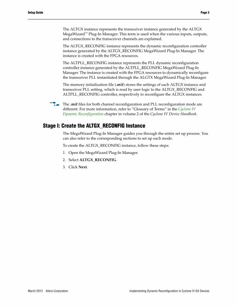
Stage I: Create the ALTGX_RECONFIG InstanceThe MegaWizard Plug-In Manager guides you through the entire set up process. You can also refer to the corresponding sections to set up each mode.
To create the ALTGX_RECONFIG instance, follow these steps:
1. Open the MegaWizard Plug-In Manager.
2. Select ALTGX_RECONFIG.
3. Click Next.
March 2013 Altera Corporation Implementing Dynamic Reconfiguration in Cyclone IV GX Devices
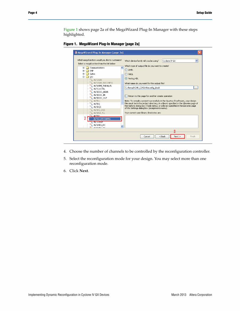
Figure 1 shows page 2a of the MegaWizard Plug-In Manager with these steps highlighted.
4. Choose the number of channels to be controlled by the reconfiguration controller.
5. Select the reconfiguration mode for your design. You may select more than one reconfiguration mode.
6. Click Next.
Figure 1. MegaWizard Plug-In Manager [page 2a]
Implementing Dynamic Reconfiguration in Cyclone IV GX Devices March 2013 Altera Corporation
Setup Guide Page 5
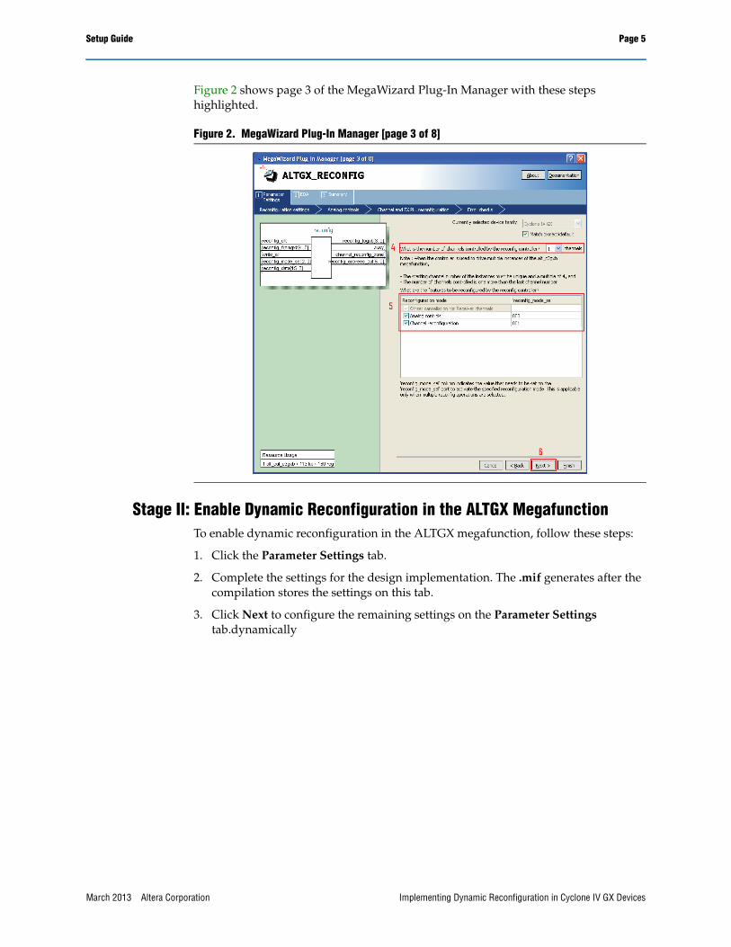
Figure 2 shows page 3 of the MegaWizard Plug-In Manager with these steps highlighted.
Stage II: Enable Dynamic Reconfiguration in the ALTGX MegafunctionTo enable dynamic reconfiguration in the ALTGX megafunction, follow these steps:
1. Click the Parameter Settings tab.
2. Complete the settings for the design implementation. The .mif generates after the compilation stores the settings on this tab.
3. Click Next to configure the remaining settings on the Parameter Settings tab.dynamically
Figure 2. MegaWizard Plug-In Manager [page 3 of 8]
March 2013 Altera Corporation Implementing Dynamic Reconfiguration in Cyclone IV GX Devices
Page 6 Setup Guide
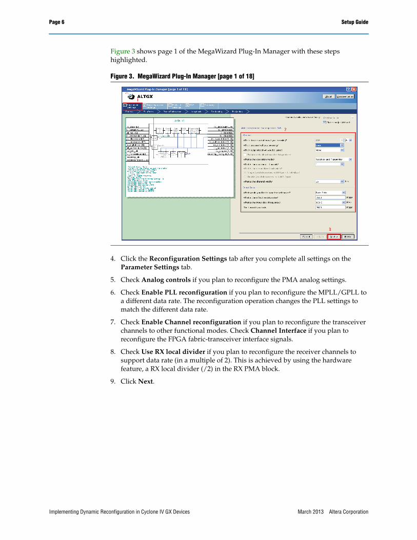
Figure 3 shows page 1 of the MegaWizard Plug-In Manager with these steps highlighted.
4. Click the Reconfiguration Settings tab after you complete all settings on the Parameter Settings tab.
5. Check Analog controls if you plan to reconfigure the PMA analog settings.
6. Check Enable PLL reconfiguration if you plan to reconfigure the MPLL/GPLL to a different data rate. The reconfiguration operation changes the PLL settings to match the different data rate.
7. Check Enable Channel reconfiguration if you plan to reconfigure the transceiver channels to other functional modes. Check Channel Interface if you plan to reconfigure the FPGA fabric-transceiver interface signals.
8. Check Use RX local divider if you plan to reconfigure the receiver channels to support data rate (in a multiple of 2). This is achieved by using the hardware feature, a RX local divider (/2) in the RX PMA block.
9. Click Next.
Figure 3. MegaWizard Plug-In Manager [page 1 of 18]
Implementing Dynamic Reconfiguration in Cyclone IV GX Devices March 2013 Altera Corporation
Setup Guide Page 7
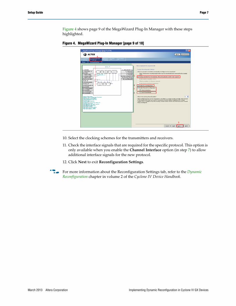
Figure 4 shows page 9 of the MegaWizard Plug-In Manager with these steps highlighted.
10. Select the clocking schemes for the transmitters and receivers.
11. Check the interface signals that are required for the specific protocol. This option is only available when you enable the Channel Interface option (in step 7) to allow additional interface signals for the new protocol.
12. Click Next to exit Reconfiguration Settings.
f For more information about the Reconfiguration Settings tab, refer to the Dynamic Reconfiguration chapter in volume 2 of the Cyclone IV Device Handbook.
Figure 4. MegaWizard Plug-In Manager [page 9 of 18]
March 2013 Altera Corporation Implementing Dynamic Reconfiguration in Cyclone IV GX Devices
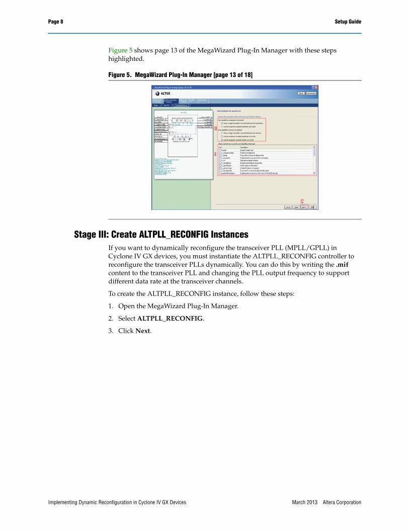
Figure 5 shows page 13 of the MegaWizard Plug-In Manager with these steps highlighted.
Stage III: Create ALTPLL_RECONFIG InstancesIf you want to dynamically reconfigure the transceiver PLL (MPLL/GPLL) in Cyclone IV GX devices, you must instantiate the ALTPLL_RECONFIG controller to reconfigure the transceiver PLLs dynamically. You can do this by writing the .mif content to the transceiver PLL and changing the PLL output frequency to support different data rate at the transceiver channels.
To create the ALTPLL_RECONFIG instance, follow these steps:
1. Open the MegaWizard Plug-In Manager.
2. Select ALTPLL_RECONFIG.
3. Click Next.
Figure 5. MegaWizard Plug-In Manager [page 13 of 18]
Implementing Dynamic Reconfiguration in Cyclone IV GX Devices March 2013 Altera Corporation
Setup Guide Page 9
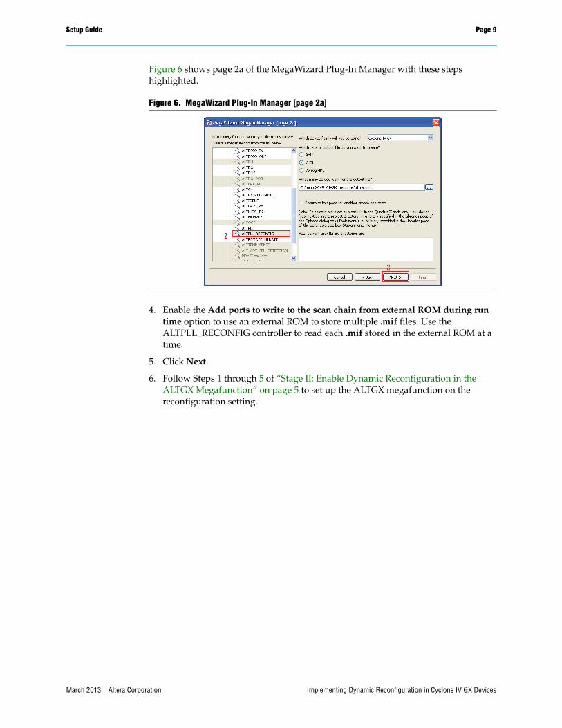
Figure 6 shows page 2a of the MegaWizard Plug-In Manager with these steps highlighted.
4. Enable the Add ports to write to the scan chain from external ROM during run time option to use an external ROM to store multiple .mif files. Use the ALTPLL_RECONFIG controller to read each .mif stored in the external ROM at a time.
5. Click Next.
6. Follow Steps 1 through 5 of “Stage II: Enable Dynamic Reconfiguration in the ALTGX Megafunction” on page 5 to set up the ALTGX megafunction on the reconfiguration setting.
Figure 6. MegaWizard Plug-In Manager [page 2a]
March 2013 Altera Corporation Implementing Dynamic Reconfiguration in Cyclone IV GX Devices
Page 10 Setup Guide
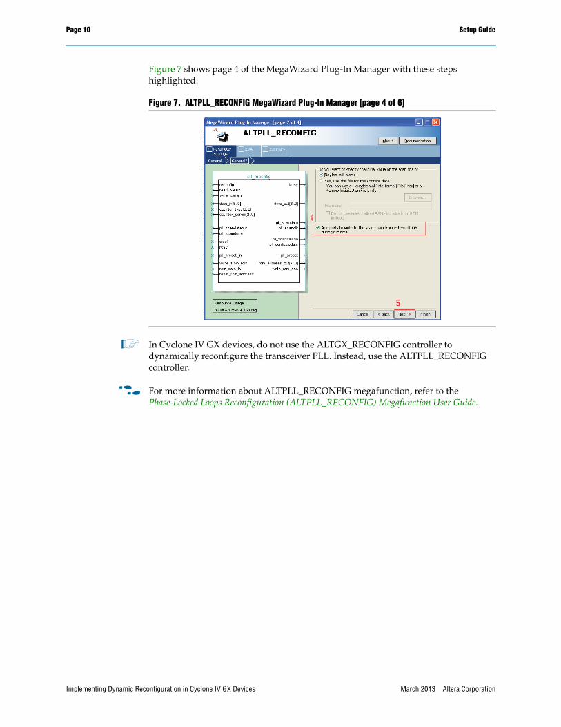
Figure 7 shows page 4 of the MegaWizard Plug-In Manager with these steps highlighted.
1 In Cyclone IV GX devices, do not use the ALTGX_RECONFIG controller to dynamically reconfigure the transceiver PLL. Instead, use the ALTPLL_RECONFIG controller.
f For more information about ALTPLL_RECONFIG megafunction, refer to the Phase-Locked Loops Reconfiguration (ALTPLL_RECONFIG) Megafunction User Guide.
Figure 7. ALTPLL_RECONFIG MegaWizard Plug-In Manager [page 4 of 6]
Implementing Dynamic Reconfiguration in Cyclone IV GX Devices March 2013 Altera Corporation
Stage IV: Connect the Clock Ports of the ALTGX, ALTGX_RECONFIG, and ALTPLL_RECONFIG Instances
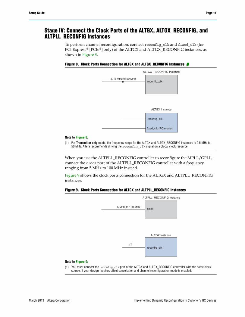
To perform channel reconfiguration, connect reconfig_clk and fixed_clk (for PCI Express® [PCIe®] only) of the ALTGX and ALTGX_RECONFIG instances, as shown in Figure 8.
When you use the ALTPLL_RECONFIG controller to reconfigure the MPLL/GPLL, connect the clock port of the ALTPLL_RECONFIG controller with a frequency ranging from 5 MHz to 100 MHz instead.
Figure 9 shows the clock ports connection for the ALTGX and ALTPLL_RECONFIG instances.
Figure 8. Clock Ports Connection for ALTGX and ALTGX_RECONFIG Instances (Note 1)
Note to Figure 8:
(1) For Transmitter only mode, the frequency range for the ALTGX and ALTGX_RECONFIG instances is 2.5 MHz to 50 MHz. Altera recommends driving the reconfig_clk signal on a global clock resource.
Figure 9. Clock Ports Connection for ALTGX and ALTPLL_RECONFIG Instances
Note to Figure 9:
(1) You must connect the reconfig_clk port of the ALTGX and ALTGX_RECONFIG controller with the same clock source, if your design requires offset cancellation and channel reconfiguration mode is enabled.
reconfig_clk
reconfig_clk
ALTGX_RECONFIG Instance
ALTGX Instance
fixed_clk (PCIe only)
37.5 MHz to 50 MHz
clock
reconfig_clk
ALTPLL_RECONFIG Instance
ALTGX Instance
5 MHz to 100 MHz
(1)
March 2013 Altera Corporation Implementing Dynamic Reconfiguration in Cyclone IV GX Devices
Page 12 Setup Guide
For a channel that is configured in Receiver only or Duplex mode, you must connect the reconfig_clk port of the ALTGX to the reconfig_clk port of the ALTGX_RECONFIG instances with the same clock source. This ensures the offset cancellation process for the receiver channels work properly. The allowed frequency range for the reconfig_clk port is 37.5 MHz to 50 MHz.
1 For more information about connecting the PLL reconfiguration controller block, refer to“Design Example for Implementing Auto-Rate Negotiation Applications with PLL Reconfiguration Mode” on page 20.
Stage V: Generate a .mif for Channel Reconfiguration and a .mif for PLL Reconfiguration
This section describes how to generate a .mif for channel reconfiguration and PLL reconfiguration modes.
Generate a .mif for Channel ReconfigurationTo generate a .mif for channel reconfiguration, perform the following steps:
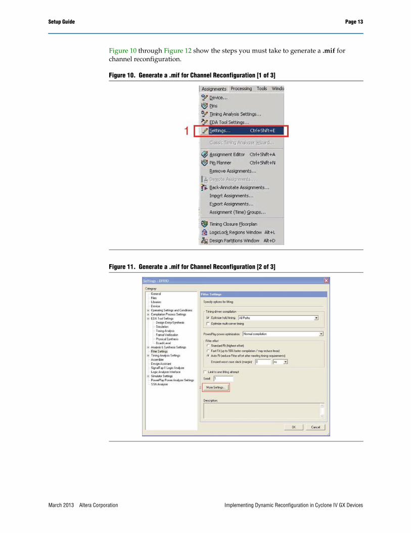
1. On the Assignments menu of the Quartus® II software, select Settings (Figure 10).
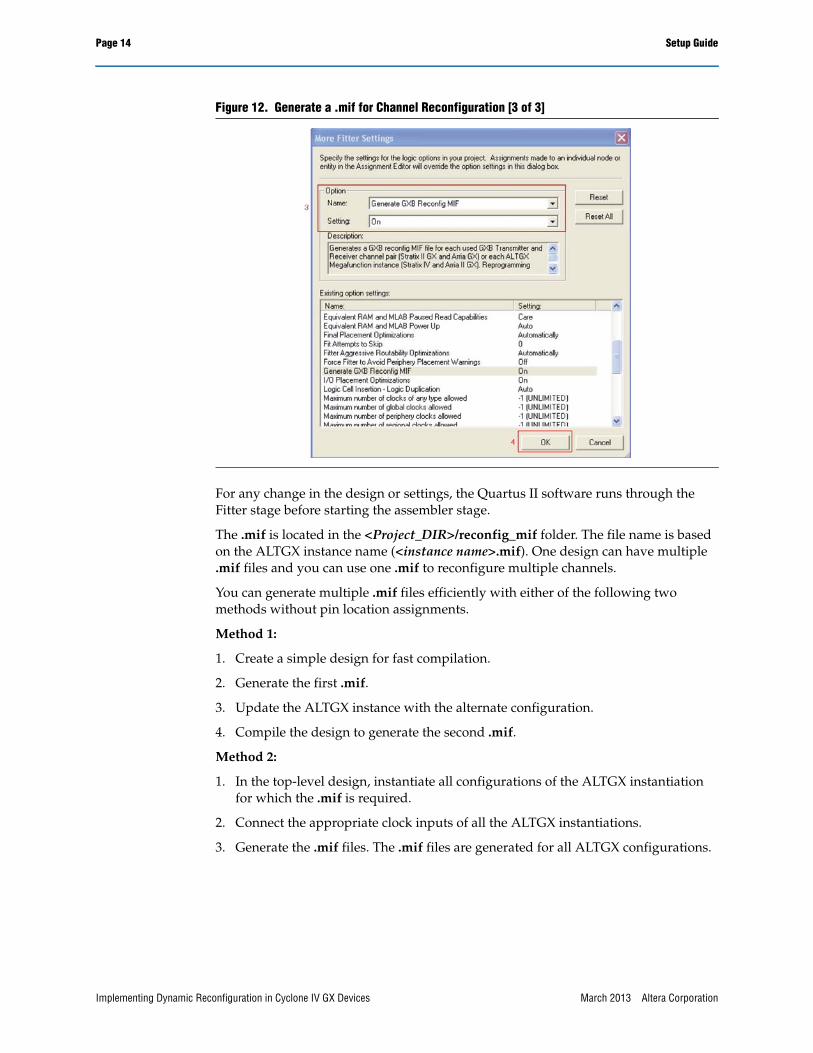
2. Select Fitter Settings, then click More Settings (Figure 11).
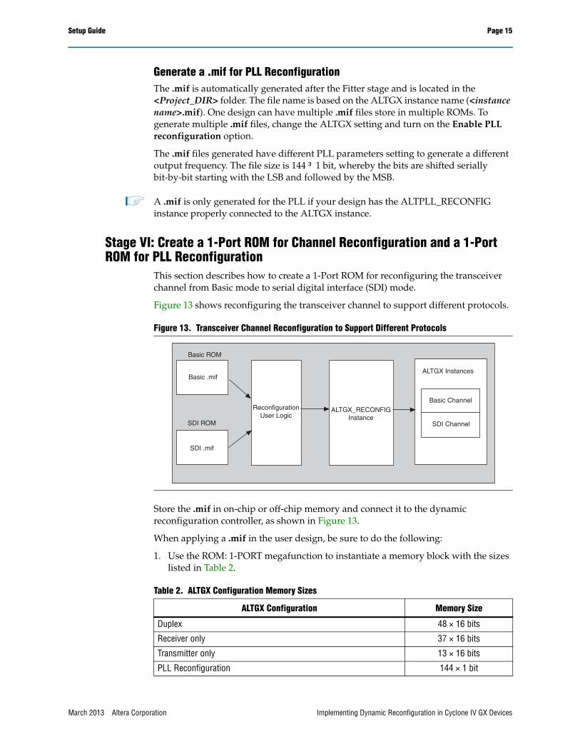
3. In the Option box of the More Fitter Settings page, set the Generate GXB Reconfig MIF option to On based on the dynamic reconfiguration mode enabled (Figure 12).
4. Click OK.
Implementing Dynamic Reconfiguration in Cyclone IV GX Devices March 2013 Altera Corporation
Setup Guide Page 13
Figure 10 through Figure 12 show the steps you must take to generate a .mif for channel reconfiguration.
Figure 10. Generate a .mif for Channel Reconfiguration [1 of 3]
Figure 11. Generate a .mif for Channel Reconfiguration [2 of 3]
March 2013 Altera Corporation Implementing Dynamic Reconfiguration in Cyclone IV GX Devices
Page 14 Setup Guide
For any change in the design or settings, the Quartus II software runs through the Fitter stage before starting the assembler stage.
The .mif is located in the <Project_DIR>/reconfig_mif folder. The file name is based on the ALTGX instance name (<instance name>.mif). One design can have multiple .mif files and you can use one .mif to reconfigure multiple channels.
You can generate multiple .mif files efficiently with either of the following two methods without pin location assignments.
Method 1:
1. Create a simple design for fast compilation.
2. Generate the first .mif.
3. Update the ALTGX instance with the alternate configuration.
4. Compile the design to generate the second .mif.
Method 2:
1. In the top-level design, instantiate all configurations of the ALTGX instantiation for which the .mif is required.
2. Connect the appropriate clock inputs of all the ALTGX instantiations.
3. Generate the .mif files. The .mif files are generated for all ALTGX configurations.
Figure 12. Generate a .mif for Channel Reconfiguration [3 of 3]
Implementing Dynamic Reconfiguration in Cyclone IV GX Devices March 2013 Altera Corporation
Setup Guide Page 15
Generate a .mif for PLL ReconfigurationThe .mif is automatically generated after the Fitter stage and is located in the <Project_DIR> folder. The file name is based on the ALTGX instance name (<instance name>.mif). One design can have multiple .mif files store in multiple ROMs. To generate multiple .mif files, change the ALTGX setting and turn on the Enable PLL reconfiguration option.
The .mif files generated have different PLL parameters setting to generate a different output frequency. The file size is 144 1 bit, whereby the bits are shifted serially bit-by-bit starting with the LSB and followed by the MSB.
1 A .mif is only generated for the PLL if your design has the ALTPLL_RECONFIG instance properly connected to the ALTGX instance.
Stage VI: Create a 1-Port ROM for Channel Reconfiguration and a 1-Port ROM for PLL Reconfiguration
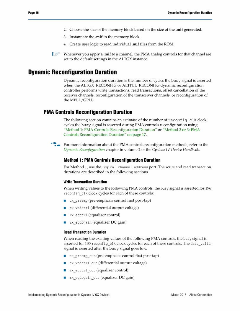
This section describes how to create a 1-Port ROM for reconfiguring the transceiver channel from Basic mode to serial digital interface (SDI) mode.
Figure 13 shows reconfiguring the transceiver channel to support different protocols.
Store the .mif in on-chip or off-chip memory and connect it to the dynamic reconfiguration controller, as shown in Figure 13.
When applying a .mif in the user design, be sure to do the following:
1. Use the ROM: 1-PORT megafunction to instantiate a memory block with the sizes listed in Table 2.
Figure 13. Transceiver Channel Reconfiguration to Support Different Protocols
Table 2. ALTGX Configuration Memory Sizes
ALTGX Configuration Memory Size
Duplex 48 × 16 bits
Receiver only 37 × 16 bits
Transmitter only 13 × 16 bits
PLL Reconfiguration 144 × 1 bit
Basic ROM
Basic .mif
SDI .mif
SDI ROM
ReconfigurationUser Logic
ALTGX_RECONFIGInstance
ALTGX Instances
Basic Channel
SDI Channel
March 2013 Altera Corporation Implementing Dynamic Reconfiguration in Cyclone IV GX Devices
Page 16 Dynamic Reconfiguration Duration
2. Choose the size of the memory block based on the size of the .mif generated.
3. Instantiate the .mif in the memory block.
4. Create user logic to read individual .mif files from the ROM.
1 Whenever you apply a .mif to a channel, the PMA analog controls for that channel are set to the default settings in the ALTGX instance.
Dynamic Reconfiguration DurationDynamic reconfiguration duration is the number of cycles the busy signal is asserted when the ALTGX_RECONFIG or ALTPLL_RECONFIG dynamic reconfiguration controller performs write transactions, read transactions, offset cancellation of the receiver channels, reconfiguration of the transceiver channels, or reconfiguration of the MPLL/GPLL.
PMA Controls Reconfiguration DurationThe following section contains an estimate of the number of reconfig_clk clock cycles the busy signal is asserted during PMA controls reconfiguration using “Method 1: PMA Controls Reconfiguration Duration” or “Method 2 or 3: PMA Controls Reconfiguration Duration” on page 17.
f For more information about the PMA controls reconfiguration methods, refer to the Dynamic Reconfiguration chapter in volume 2 of the Cyclone IV Device Handbook.
Method 1: PMA Controls Reconfiguration DurationFor Method 1, use the logical_channel_address port. The write and read transaction durations are described in the following sections.
Write Transaction Duration
When writing values to the following PMA controls, the busy signal is asserted for 196 reconfig_clk clock cycles for each of these controls:
■ tx_preemp (pre-emphasis control first post-tap)
■ tx_vodctrl (differential output voltage)
■ rx_eqctrl (equalizer control)
■ rx_eqdcgain (equalizer DC gain)
Read Transaction Duration
When reading the existing values of the following PMA controls, the busy signal is asserted for 135 reconfig_clk clock cycles for each of these controls. The data_valid signal is asserted after the busy signal goes low.
■ tx_preemp_out (pre-emphasis control first post-tap)
■ tx_vodctrl_out (differential output voltage)
■ rx_eqctrl_out (equalizer control)
■ rx_eqdcgain_out (equalizer DC gain)
Implementing Dynamic Reconfiguration in Cyclone IV GX Devices March 2013 Altera Corporation
Method 2 or 3: PMA Controls Reconfiguration DurationFor Methods 2 and 3, do not use the logical_channel_address port. The write and read transaction durations are described in the following sections.
Write Transaction Duration
When writing values to the following PMA controls, the busy signal is asserted for 196 reconfig_clk clock cycles per channel for each of these controls:
■ tx_preemp (pre-emphasis control first post-tap)
■ tx_vodctrl (differential output voltage)
■ rx_eqctrl (equalizer control)
■ rx_eqdcgain (equalizer DC gain)
Read Transaction Duration
When reading the existing values of the following PMA controls, the busy signal is asserted for 135 reconfig_clk clock cycles per channel for each of these controls. The data_valid signal is asserted after the busy signal goes low.
■ tx_preemp_out (pre-emphasis control first post-tap)
■ tx_vodctrl_out (differential output voltage)
■ rx_eqctrl_out (equalizer control)
■ rx_eqdcgain_out (equalizer DC gain)
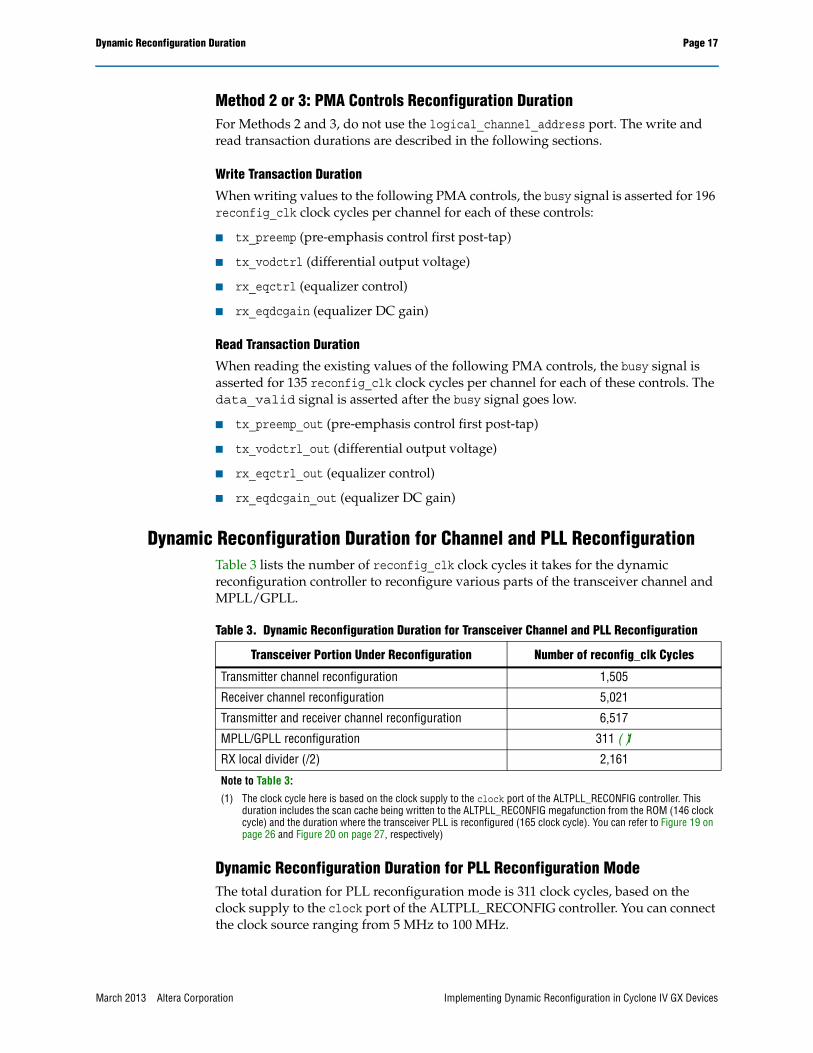
Dynamic Reconfiguration Duration for Channel and PLL ReconfigurationTable 3 lists the number of reconfig_clk clock cycles it takes for the dynamic reconfiguration controller to reconfigure various parts of the transceiver channel and MPLL/GPLL.
Dynamic Reconfiguration Duration for PLL Reconfiguration ModeThe total duration for PLL reconfiguration mode is 311 clock cycles, based on the clock supply to the clock port of the ALTPLL_RECONFIG controller. You can connect the clock source ranging from 5 MHz to 100 MHz.
Table 3. Dynamic Reconfiguration Duration for Transceiver Channel and PLL Reconfiguration
Transceiver Portion Under Reconfiguration Number of reconfig_clk Cycles
Transmitter channel reconfiguration 1,505
Receiver channel reconfiguration 5,021
Transmitter and receiver channel reconfiguration 6,517
MPLL/GPLL reconfiguration 311 (1)
RX local divider (/2) 2,161
Note to Table 3:
(1) The clock cycle here is based on the clock supply to the clock port of the ALTPLL_RECONFIG controller. This duration includes the scan cache being written to the ALTPLL_RECONFIG megafunction from the ROM (146 clock cycle) and the duration where the transceiver PLL is reconfigured (165 clock cycle). You can refer to Figure 19 on page 26 and Figure 20 on page 27, respectively)
March 2013 Altera Corporation Implementing Dynamic Reconfiguration in Cyclone IV GX Devices
Page 18 Combining Transceiver Channels with Dynamic Reconfiguration Enabled
f For more information about the PLL reconfiguration connection, refer to “Design Example for Implementing Auto-Rate Negotiation Applications with PLL Reconfiguration Mode” on page 20.
Combining Transceiver Channels with Dynamic Reconfiguration Enabled
You can combine the transceiver channels in your design into the same physical transceiver block by assigning the tx_dataout and rx_datain pins of the channels to the same transceiver block.
RequirementsWhen you enable dynamic reconfiguration, the Quartus II software has certain requirements for combining multiple transceiver channels in the same physical transceiver block:
■ All channels that you want to combine in the same transceiver block must have the same options enabled on the Reconfiguration Settings tab of the ALTGX MegaWizard Plug-In Manager. For example, when you enable the Analog controls (VOD, pre-emphasis, equalization and DC gain) option, you must enable the same option for all the other channels to be combined.
■ When combining a Transmitter only channel with a Receiver only channel, both must go through a reset sequence, even if the transmitter or receiver is reconfigured.
■ Combining channels does not affect the logical channel address of the combined channel. For example, before combining, logical_channel_address 0 is a Transmitter only channel and logical_channel_address 4 is a Receiver only channel. After combining, the addresses remain unchanged, although they are physically the same channel.
■ All channels must be controlled by the same ALTGX_RECONFIG (dynamic reconfiguration controller) instance. The transceiver channels connected to multiple ALTGX_RECONFIG instances cannot be combined into the same physical transceiver block, even if they are configured to the same functional mode and data rate.
Design Example with Analog ControlThe following example shows one possible topology with one ALTGX_RECONFIG instance to control multiple ALTGX instances using “Method 1: PMA Controls Reconfiguration Duration” on page 16.
One Reconfiguration Controller Connected to Multiple ALTGX InstancesConsider the following design:
■ ALTGX_RECONFIG instance
■ ALTGX instance 1 with four channels
■ ALTGX instance 2 with three channels
Implementing Dynamic Reconfiguration in Cyclone IV GX Devices March 2013 Altera Corporation
Design Example with Analog Control Page 19
Assume the following for this example:
■ ALTGX instance 1 and ALTGX instance 2 cannot be physically packed into the same transceiver block.
■ One dynamic reconfiguration controller controls both the ALTGX instances.
■ You want to dynamically reconfigure the transmit VOD PMA control (tx_vodctrl) of the first channel of ALTGX instance 1 and receiver equalization PMA control (rx_eqctrl) of the second channel of ALTGX instance 2.
■ You are using the logical channel addressing feature in the ALTGX megafunction.
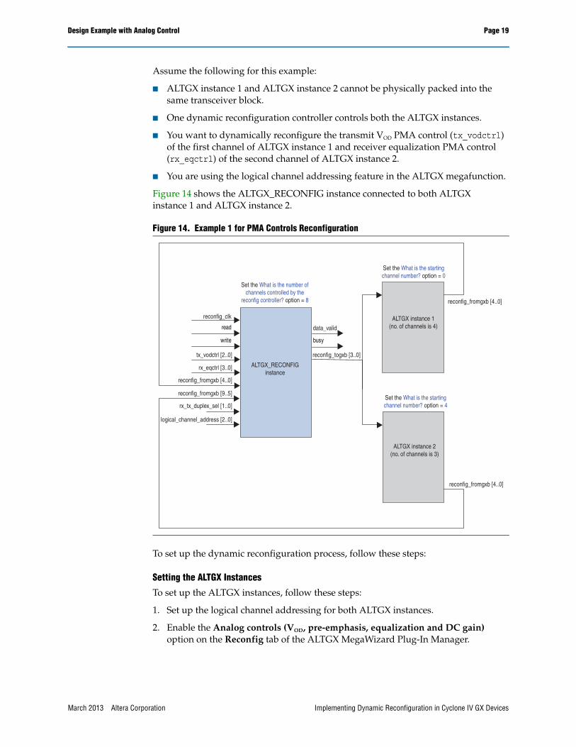
Figure 14 shows the ALTGX_RECONFIG instance connected to both ALTGX instance 1 and ALTGX instance 2.
To set up the dynamic reconfiguration process, follow these steps:
Setting the ALTGX Instances
To set up the ALTGX instances, follow these steps:
1. Set up the logical channel addressing for both ALTGX instances.
2. Enable the Analog controls (VOD, pre-emphasis, equalization and DC gain) option on the Reconfig tab of the ALTGX MegaWizard Plug-In Manager.
Figure 14. Example 1 for PMA Controls Reconfiguration
read
write busy
Set the What is the startingchannel number? option = 0
reconfig_fromgxb [4..0]
ALTGX instance 1(no. of channels is 4)
Set the What is the startingchannel number? option = 4
ALTGX instance 2(no. of channels is 3)
reconfig_fromgxb [4..0]
data_valid
reconfig_togxb [3..0]
ALTGX_RECONFIGinstance
logical_channel_address [2..0]
rx_tx_duplex_sel [1..0]
reconfig_fromgxb [9..5]
reconfig_fromgxb [4..0]
rx_eqctrl [3..0]
tx_vodctrl [2..0]
reconfig_clk
Set the What is the number ofchannels controlled by the
reconfig controller? option = 8
March 2013 Altera Corporation Implementing Dynamic Reconfiguration in Cyclone IV GX Devices
Page 20 Design Example with PLL Reconfiguration Mode and Channel Reconfiguration Mode (Using RX Local Divider)
Setting the ALTGX_RECONFIG Instance
To set up the ALTGX_RECONFIG instance, follow these steps:
1. Set up the logical channel control for the ALTGX_RECONFIG instance.
2. Select the rx_tx_duplex_sel [1..0] port on the Error checks tab of the ALTGX_RECONFIG MegaWizard Plug-In Manager.
3. Select the tx_vodctrl and rx_eqctrl controls, which is 3 bits wide and 4 bits wide, respectively.
ALTGX Instances and ALTGX_RECONFIG Instance Connections
To connect the ALTGX instances to the ALTGX_RECONFIG instance, refer to the steps shown in “Stage I: Create the ALTGX_RECONFIG Instance” on page 3.
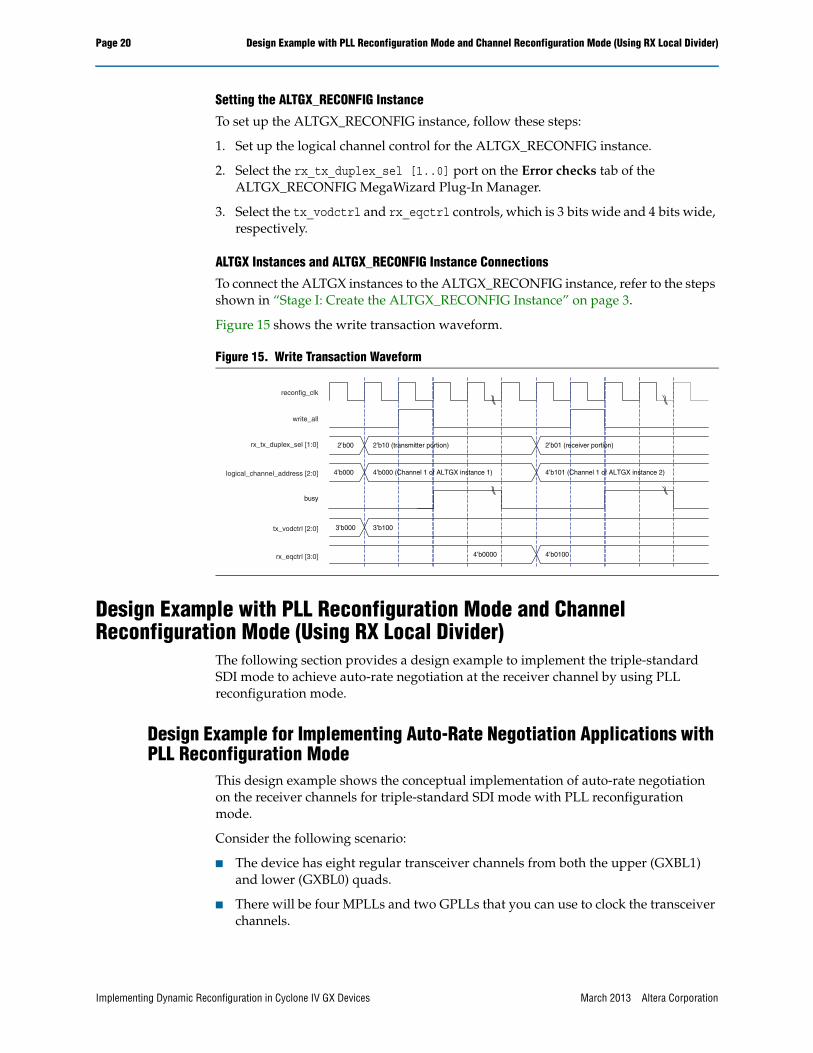
Figure 15 shows the write transaction waveform.
Design Example with PLL Reconfiguration Mode and Channel Reconfiguration Mode (Using RX Local Divider)
The following section provides a design example to implement the triple-standard SDI mode to achieve auto-rate negotiation at the receiver channel by using PLL reconfiguration mode.
Design Example for Implementing Auto-Rate Negotiation Applications with PLL Reconfiguration Mode
This design example shows the conceptual implementation of auto-rate negotiation on the receiver channels for triple-standard SDI mode with PLL reconfiguration mode.
Consider the following scenario:
■ The device has eight regular transceiver channels from both the upper (GXBL1) and lower (GXBL0) quads.
■ There will be four MPLLs and two GPLLs that you can use to clock the transceiver channels.
Figure 15. Write Transaction Waveform
4’b000
busy
2’b00
reconfig_clk
write_all
rx_tx_duplex_sel [1:0]
logical_channel_address [2:0]
tx_vodctrl [2:0]
rx_eqctrl [3:0]
3’b000
2’b10 (transmitter portion)
4’b000 (Channel 1 of ALTGX instance 1)
3’b100
4’b0000 4’b0100
4’b101 (Channel 1 of ALTGX instance 2)
2’b01 (receiver portion)
Implementing Dynamic Reconfiguration in Cyclone IV GX Devices March 2013 Altera Corporation
Design Example with PLL Reconfiguration Mode and Channel Reconfiguration Mode (Using RX Local Divider) Page 21
■ You want to reconfigure all channels in Transmitter only or Receiver only mode for triple-standard SDI mode.
■ All Transmitter only and Receiver only channels are reconfigured independently.
For example, assume you want to switch between the following two modes:
Mode1:
■ Four transmitter channels running at 2.97 Gbps clocked by GPLL1 and GPLL2.
■ Four receiver channels running at 2.97 Gbps clocked by MPLL5, MPLL6, MPLL7, and MPLL8.
■ All input reference clocks are connected to 148.5 MHz sources.
■ The transmitter and receiver will be running at 2.97 Gbps (3G-SDI mode).
Mode2:
■ Four transmitter channels running at 2.97 Gbps clocked by GPLL1 and GPLL2.
■ Four receiver channels running at 1.485 Gbps clocked by MPLL5, MPLL6, MPLL7, and MPLL8. Each receiving channel may switch to a different data rate at a different time interval.
■ All input reference clocks are connected to 148.5 MHz sources.
■ The transmitter will be transmitting data at 2.97 Gbps (3G-SDI) but the receiver will be receiving data at 1.485 Gbps (HD-SDI) (with different receiver channels switch rate at a different time interval).
1 In this example, you have to implement the oversample logic in the FPGA core to oversample the transmitting data.
March 2013 Altera Corporation Implementing Dynamic Reconfiguration in Cyclone IV GX Devices
Page 22 Design Example with PLL Reconfiguration Mode and Channel Reconfiguration Mode (Using RX Local Divider)
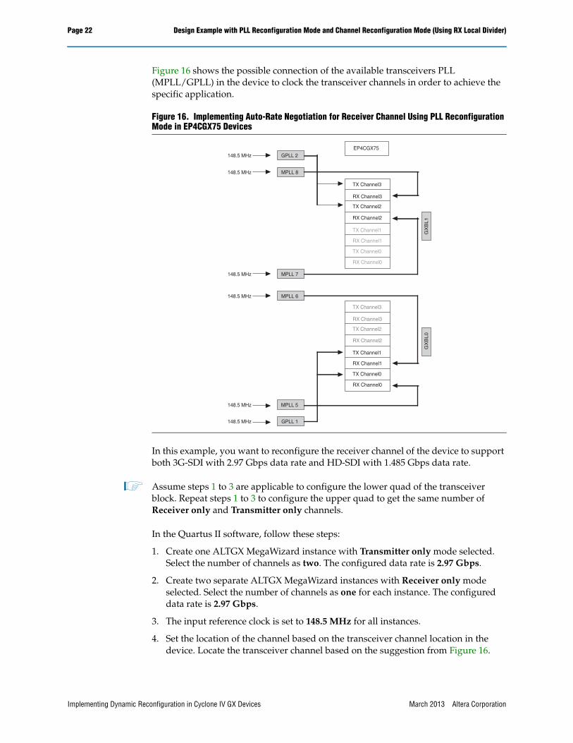
Figure 16 shows the possible connection of the available transceivers PLL (MPLL/GPLL) in the device to clock the transceiver channels in order to achieve the specific application.
In this example, you want to reconfigure the receiver channel of the device to support both 3G-SDI with 2.97 Gbps data rate and HD-SDI with 1.485 Gbps data rate.
1 Assume steps 1 to 3 are applicable to configure the lower quad of the transceiver block. Repeat steps 1 to 3 to configure the upper quad to get the same number of Receiver only and Transmitter only channels.
In the Quartus II software, follow these steps:
1. Create one ALTGX MegaWizard instance with Transmitter only mode selected. Select the number of channels as two. The configured data rate is 2.97 Gbps.
2. Create two separate ALTGX MegaWizard instances with Receiver only mode selected. Select the number of channels as one for each instance. The configured data rate is 2.97 Gbps.
3. The input reference clock is set to 148.5 MHz for all instances.
4. Set the location of the channel based on the transceiver channel location in the device. Locate the transceiver channel based on the suggestion from Figure 16.
Figure 16. Implementing Auto-Rate Negotiation for Receiver Channel Using PLL Reconfiguration Mode in EP4CGX75 Devices
TX Channel3
RX Channel3
TX Channel2
RX Channel2
TX Channel1
RX Channel1
TX Channel0
RX Channel0
TX Channel3
RX Channel3
TX Channel2
RX Channel2
TX Channel1
RX Channel1
TX Channel0
RX Channel0
GPLL 2
MPLL 8
148.5 MHz
148.5 MHz
MPLL 7
MPLL 6
148.5 MHz
148.5 MHz
MPLL 5
GPLL 1
148.5 MHz
148.5 MHzG
XB
L1
GX
BL0
EP4CGX75
Implementing Dynamic Reconfiguration in Cyclone IV GX Devices March 2013 Altera Corporation
Design Example with PLL Reconfiguration Mode and Channel Reconfiguration Mode (Using RX Local Divider) Page 23
f For more information about the pin information, refer to Cyclone IV Device Pin-Out Files.
5. Assign the transceiver PLL location from the RTL viewer under the Netlist Viewer section. Double click on the instances and navigate to the ALTPLL instantiated through the ALTGX MegaWizard Plug-In Manager. Locate the transceiver PLL based on Figure 16.
6. Instantiate the ALTPLL_RECONFIG MegaWizard Plug-In Manager instance as explained in “Stage III: Create ALTPLL_RECONFIG Instances” on page 8 to perform PLL reconfiguration.
7. Turn on the Enable PLL Reconfiguration option in the ALTGX under the Reconfiguration setting tab. When you turn on this option, the .mif files are auto-generated, as explained in “Stage II: Enable Dynamic Reconfiguration in the ALTGX Megafunction” on page 5.
8. Compile the design. There are three .mif files generated based on the three ALTGX instances.
■ One .mif is generated for the Transmitter only channel. (In the discussion of this design example, the .mif is not used. In SDI mode, you do not need to reconfigure the transmitter channel rate when switching from 2.97 Gbps to 1.485 Gbps).
■ Two .mif files are generated for the Receiver only channel configured in two separate ALTGX instances. These .mif files are generated with the setting of the PLL running at 2.97 Gbps. Use only one .mif when you want to reconfigure the receiver channel to receive data rate from 1.485 Gbps to 2.97 Gbps.
9. Create another .mif for the Receiver only channel mode to run at 1.485 Gbps. Do this by instantiating one of the Receiver only mode channels and set the Effective data rate option to 1.485 Gbps. Run the fitter and the .mif is generated. Use this .mif when you want to reconfigure the receiver channel to receive data rate from 2.97 Gbps to 1.485 Gbps.
10. Create an external ROM to store the .mif files used to reconfigure the receiver channels from the data rate 2.97 Gbps to 1.485 Gbps based on “Stage VI: Create a 1-Port ROM for Channel Reconfiguration and a 1-Port ROM for PLL Reconfiguration” on page 15. You must have two external ROM instances, one connected to each of the ALTPLL_RECONFIG controllers.
March 2013 Altera Corporation Implementing Dynamic Reconfiguration in Cyclone IV GX Devices
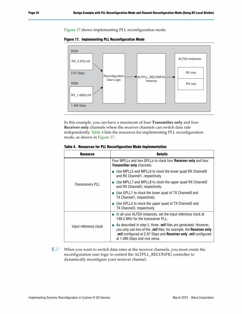
In this example, you can have a maximum of four Transmitter only and four Receiver only channels where the receiver channels can switch data rate independently. Table 4 lists the resources for implementing PLL reconfiguration mode, as shown in Figure 17.
1 When you want to switch data rates at the receiver channels, you must create the reconfiguration user logic to control the ALTPLL_RECONFIG controller to dynamically reconfigure your receiver channel.
Figure 17. Implementing PLL Reconfiguration Mode
Table 4. Resources for PLL Reconfiguration Mode Implementation
Resource Details
Transceivers PLL
Four MPLLs and two GPLLs to clock four Receiver only and four Transmitter only channels:
■ Use MPLL5 and MPLL6 to clock the lower quad RX Channel0 and RX Channel1, respectively.
■ Use MPLL7 and MPLL8 to clock the upper quad RX Channel2 and RX Channel3, respectively.
■ Use GPLL1 to clock the lower quad of TX Channel0 and TX Channel1, respectively.
■ Use GPLL2 to clock the upper quad of TX Channel2 and TX Channel3, respectively.
Input reference clock
■ In all your ALTGX instances, set the input reference clock at 148.5 MHz for the transceiver PLL.
■ As described in step 8, three .mif files are generated. However, you only use two of the .mif files; for example, the Receiver only .mif configured at 2.97 Gbps and Receiver only .mif configured at 1.485 Gbps and vice versa.
ROM
RX_1.485G.mif
ROM
ReconfigurationUser Logic
ALTPLL_RECONFIGInstance
ALTGX Instances
RX only
RX only
RX_2.97G.mif
2.97 Gbps
1.485 Gbps
Implementing Dynamic Reconfiguration in Cyclone IV GX Devices March 2013 Altera Corporation
Design Example w
ith PLL Reconfiguration Mode and Channel Reconfiguration M
ode (Using RX Local Divider)Page
25
March 2013
Altera CorporationIm
plementing Dynam
ic Reconfiguration in Cyclone IV GX Devices
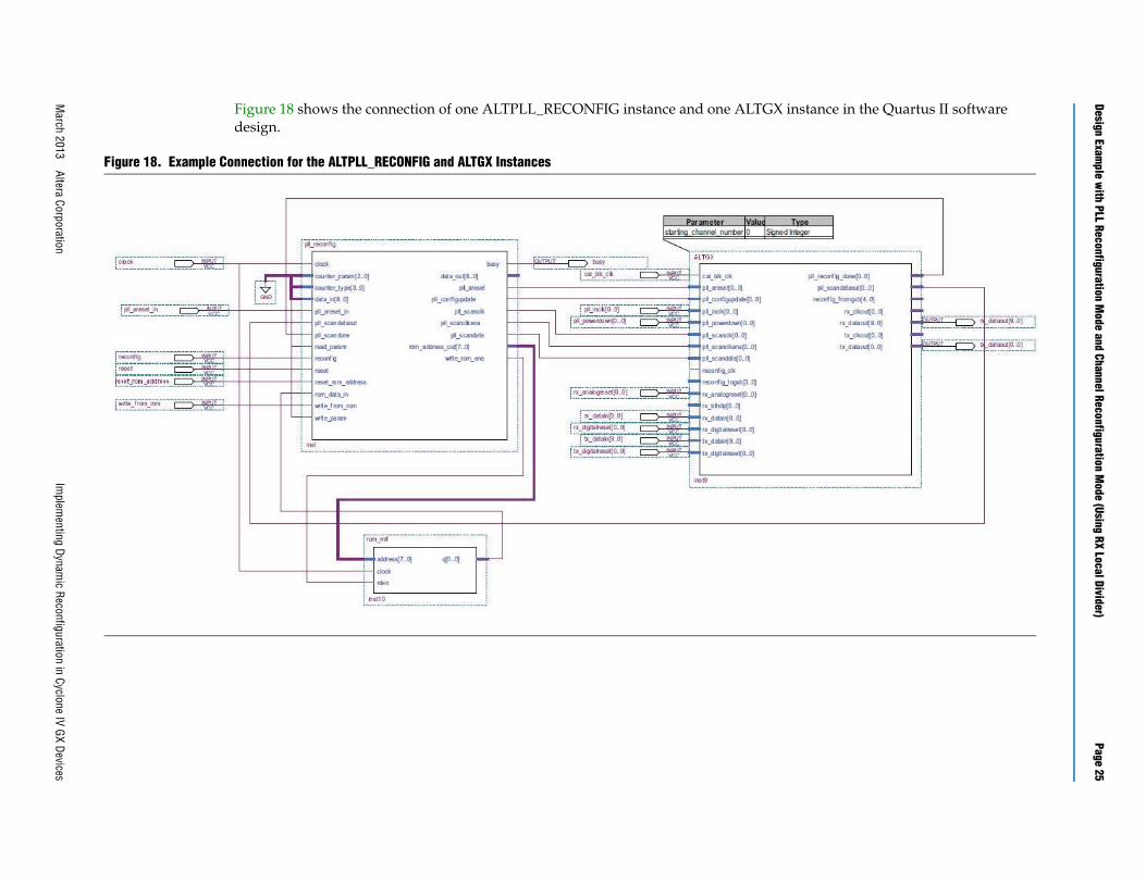
stance in the Quartus II software
Figure 18 shows the connection of one ALTPLL_RECONFIG instance and one ALTGX indesign.
Figure 18. Example Connection for the ALTPLL_RECONFIG and ALTGX Instances
Page 26 Design Example with PLL Reconfiguration Mode and Channel Reconfiguration Mode (Using RX Local Divider)
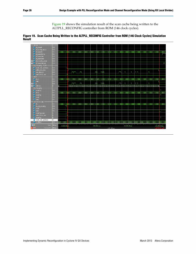
Figure 19 shows the simulation result of the scan cache being written to the ALTPLL_RECONFIG controller from ROM (146 clock cycles).
Figure 19. Scan Cache Being Written to the ALTPLL_RECONFIG Controller from ROM (146 Clock Cycles) Simulation Result
Implementing Dynamic Reconfiguration in Cyclone IV GX Devices March 2013 Altera Corporation
Design Example with PLL Reconfiguration Mode and Channel Reconfiguration Mode (Using RX Local Divider) Page 27
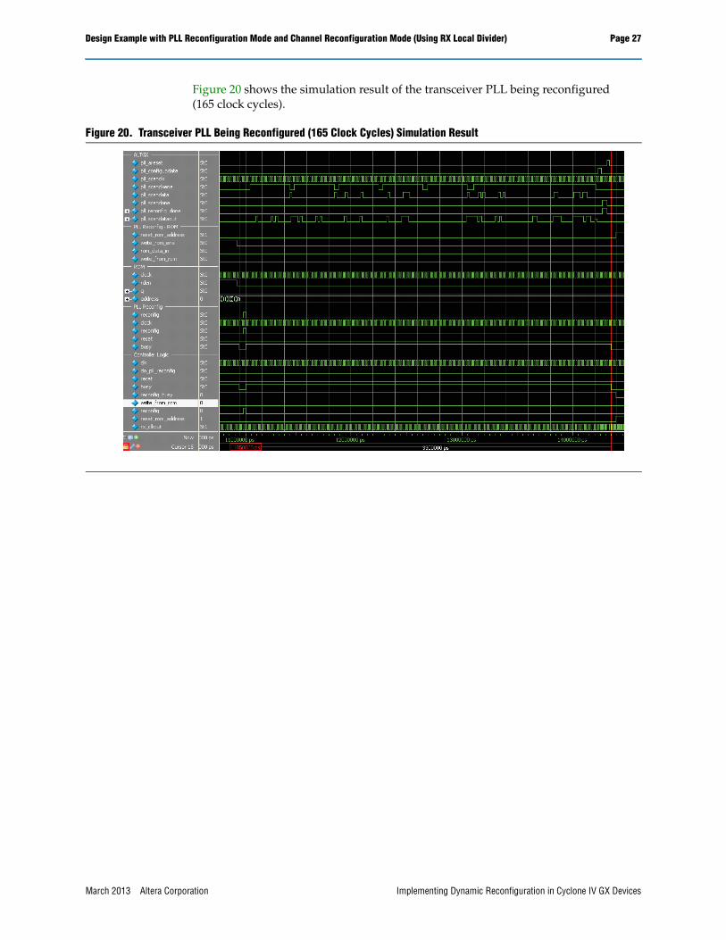
Figure 20 shows the simulation result of the transceiver PLL being reconfigured (165 clock cycles).
Figure 20. Transceiver PLL Being Reconfigured (165 Clock Cycles) Simulation Result
March 2013 Altera Corporation Implementing Dynamic Reconfiguration in Cyclone IV GX Devices
Page 28 Design Example with PLL Reconfiguration Mode and Channel Reconfiguration Mode (Using RX Local Divider)
Design Example for Implementing Auto-Rate Negotiation Applications with Channel Reconfiguration Mode (Using RX Local Divider)
This section provides a conceptual design example for implementing the triple-standard SDI mode to auto-negotiation for data rate changes at the receiver channel (in a multiple of two) by using the RX local divider (/2) available in the Cyclone IV GX transceiver channel.
f For more information about the RX local divider, refer to the Cyclone IV Transceiver Architecture chapter in volume 2 of the Cyclone IV Device Handbook.
Consider the same example in “Design Example for Implementing Auto-Rate Negotiation Applications with PLL Reconfiguration Mode” on page 20 where you want to implement the triple-standard SDI mode with the receiver channel to auto-negotiate the data rate to accomodate the need of different video formats received at the inputs.
In this section, the same scenario and modes are used to reconfigure the data rate from 2.97 Gbps to 1.485 Gbps. However, you can choose to use channel reconfiguration mode, which uses the RX local divider (/2) that is available in every receiver channel.
1 The RX local divider (/2) is a hardware feature on Cyclone IV GX device. It is supported and available in EP4CGX30 (F484 package), EP4CGX50, and EP4CGX75 devices. EP4CGX15, EP4CGX22, EP4CGX30 (F169 and F324 packages), and EP4CGX150 devices do not support this hardware feature.
Consider the same scenario:
■ The device has eight regular transceiver channels from both the upper (GXBL1) and lower (GXBL0) quads.
■ There will be four MPLLs and two GPLLs that you can use to clock the transceiver channels.
■ You want to reconfigure all channels in Transmitter only or Receiver only mode for triple-standard SDI mode.
■ All Transmitter only and Receiver only channels are reconfigured independently.
For example, assume you want to switch between the following two modes:
Mode1:
■ Four transmitter channels for both lower and upper quads running at 2.97 Gbps clocked by four separate GPLL1, GPLL2, MPLL6, and MPLL7, respectively.
■ Four receiver channels for both lower and upper quads running at 2.97 Gbps clocked by two separate MPLL5 and MPLL8.
■ All input reference clocks are connected to 148.5 MHz reference sources.
■ The transmitter and the receiver will be running at 2.97 Gbps (3G-SDI mode).
Mode2:
■ Four transmitter channels for both lower and upper quads running at 2.97 Gbps clocked by four separate GPLL1, GPLL2, MPLL6, and MPLL7, respectively.
Implementing Dynamic Reconfiguration in Cyclone IV GX Devices March 2013 Altera Corporation
Design Example with PLL Reconfiguration Mode and Channel Reconfiguration Mode (Using RX Local Divider) Page 29
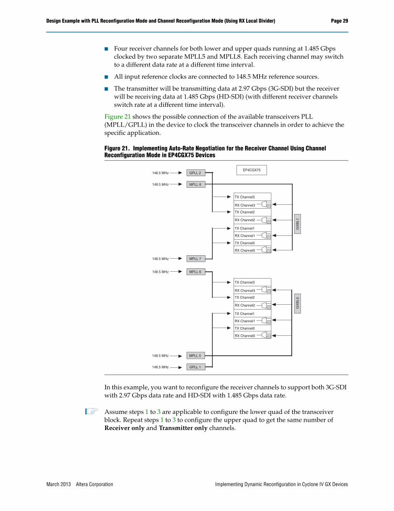
■ Four receiver channels for both lower and upper quads running at 1.485 Gbps clocked by two separate MPLL5 and MPLL8. Each receiving channel may switch to a different data rate at a different time interval.
■ All input reference clocks are connected to 148.5 MHz reference sources.
■ The transmitter will be transmitting data at 2.97 Gbps (3G-SDI) but the receiver will be receiving data at 1.485 Gbps (HD-SDI) (with different receiver channels switch rate at a different time interval).
Figure 21 shows the possible connection of the available transceivers PLL (MPLL/GPLL) in the device to clock the transceiver channels in order to achieve the specific application.
In this example, you want to reconfigure the receiver channels to support both 3G-SDI with 2.97 Gbps data rate and HD-SDI with 1.485 Gbps data rate.
1 Assume steps 1 to 3 are applicable to configure the lower quad of the transceiver block. Repeat steps 1 to 3 to configure the upper quad to get the same number of Receiver only and Transmitter only channels.
Figure 21. Implementing Auto-Rate Negotiation for the Receiver Channel Using Channel Reconfiguration Mode in EP4CGX75 Devices
GPLL 2
MPLL 8
148.5 MHz
148.5 MHz
MPLL 7
MPLL 6
148.5 MHz
148.5 MHz
MPLL 5
GPLL 1
148.5 MHz
148.5 MHz
GX
BL1
GX
BL0
EP4CGX75
TX Channel3
RX Channel3
TX Channel2
RX Channel2
TX Channel1
RX Channel1
TX Channel0
RX Channel0
/2
/2
/2
/2
TX Channel3
RX Channel3
TX Channel2
RX Channel2
TX Channel1
RX Channel1
TX Channel0
RX Channel0
/2
/2
/2
/2
March 2013 Altera Corporation Implementing Dynamic Reconfiguration in Cyclone IV GX Devices
Page 30 Design Example with PLL Reconfiguration Mode and Channel Reconfiguration Mode (Using RX Local Divider)
You must perform the following steps in the Quartus II software:
1. Create two separate ALTGX MegaWizard Plug-In Manager instances with Transmitter only mode selected. Select the number of channel as two for each instances. In total, there are four Transmitter only channels clocked by two different transceiver PLL. The configured data rate is 2.97 Gbps.
2. Create one ALTGX MegaWizard Plug-In Manager instance with Receiver only mode selected. Select the number of channel as four. In total, there are four Receiver only channels clocked by the same PLL. The configured data rate is 2.97 Gbps.
3. All input reference clocks are set to 148.5 MHz.
4. Set the location of the channel based on the transceiver channel location in the device. Locate the transceiver channel based on Figure 21.
f For more information about the pin information, refer to Cyclone IV Device Pin-Out Files.
5. Assign the transceiver PLL location from the RTL viewer under the Netlist Viewer section. Double click on the instances and navigate to ALTPLL instantiated through the ALTGX MegaWizard Plug-In Manager. Locate the transceiver PLL based on Figure 21.
6. Connect the ALTGX_RECONFIG MegaWizard Plug-In Manager instance as explained in “Stage I: Create the ALTGX_RECONFIG Instance” on page 3 to perform channel reconfiguration.
7. Turn on the Enable Channel Reconfiguration option in the ALTGX under Reconfiguration setting tab. Turn on the Use RX local divider option to enable the local divider to support the incoming data rate in a multiple of two.
8. For channel reconfiguration, the .mif will be generated by turning on the Generate GXB Reconfig MIF option in the Quartus II setting. Follow the steps as discussed in “Stage V: Generate a .mif for Channel Reconfiguration and a .mif for PLL Reconfiguration” on page 12.
9. Compile the design. There will be two .mif files generated based on the ALTGX instances configured for Receiver only channel when you enable or disable the RX local divider in a separate configuration.
■ One .mif is generated for the Receiver only channel which enables the Use RX local divider option. This .mif enables the path to the RX local divider (/2). The data rate is further divided into half of the receiving data rate.
■ One .mif is generated for the Receiver only channel without enabling the Use RX local divider option. In this .mif, the RX local divider (/2) is bypassed and the receiver data path takes in the data rate as it is.
10. Create an external ROM to store the .mif files used to reconfigure the receiver channels from data rate 2.97 Gbps to 1.485 Gbps based on “Stage VI: Create a 1-Port ROM for Channel Reconfiguration and a 1-Port ROM for PLL Reconfiguration” on page 15. There must be two external ROMs connected to each of the ALTGX_RECONFIG controllers. Each of the external ROMs stores one of the .mif generated (as described in step 9).
Implementing Dynamic Reconfiguration in Cyclone IV GX Devices March 2013 Altera Corporation
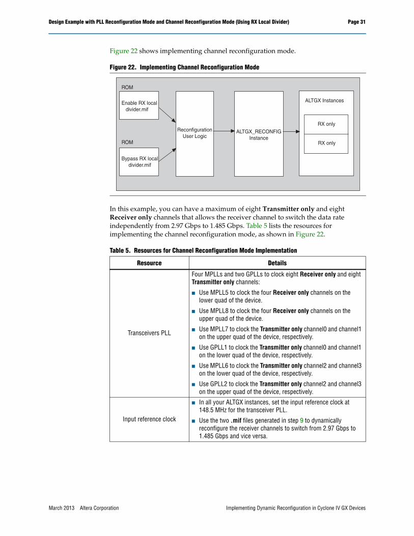
In this example, you can have a maximum of eight Transmitter only and eight Receiver only channels that allows the receiver channel to switch the data rate independently from 2.97 Gbps to 1.485 Gbps. Table 5 lists the resources for implementing the channel reconfiguration mode, as shown in Figure 22.