AN ABSTRACT OF THE THESIS OF Zhao-ming Sonct for the degree of Master of Science in Industrial and Manufacturing Engineering Pressented on January 30, 1991 . Title: Package Inspection with a Machine Vision System Redacted for Privacy Abstract approved: -- Dr. Eugene Fichter Machine Vision has been extensively applied in industry. This thesis project, which originated with a local food processor, applies a vision system to inspection of packages for cosmetric errors. The basic elements and theory of the machine vision system are introduced, and some image processing techniques, such as histogram analysis, thresholding, and SRI algorithm, are utilized in this thesis. Computer programs written in C and Pascal are described. Hardware setup and computer interface, such as RS-232 serial interface, parallel digital I/O interface, conveyor control, and incremental shaft encoder, are described. Test results are presented and discussed.
Transcript
AN ABSTRACT OF THE THESIS OF
Zhao-ming Sonct for the degree of Master of Science in
Industrial and Manufacturing Engineering Pressented on
January 30, 1991 .
Title: Package Inspection with a Machine Vision System
Redacted for PrivacyAbstract approved: --
Dr. Eugene Fichter
Machine Vision has been extensively applied in industry.
This thesis project, which originated with a local food
processor, applies a vision system to inspection of packages
for cosmetric errors. The basic elements and theory of the
machine vision system are introduced, and some image
processing techniques, such as histogram analysis,
thresholding, and SRI algorithm, are utilized in this thesis.
Computer programs written in C and Pascal are described.
Hardware setup and computer interface, such as RS-232 serial
interface, parallel digital I/O interface, conveyor control,
and incremental shaft encoder, are described. Test results
are presented and discussed.
Package Inspection with a Machine Vision System
by
Zhao-ming Song
A THESIS
submitted to
Oregon State University
in partial fulfillment of
the requirements for the
degree of
Master of Science
Completed January 30, 1991
Commencement June, 1991
APPROVED:
Redacted for PrivacyAssoc. roc-ofessor of Industrial and Manufacturing Engineeringin charge of major
Redacted for PrivacyHead of Industrial and Manufacturing Engineering Department
Redacted for PrivacynDean of GraC to 5cnooKi
Date thesis is presented January 30, 1991
Typed by Zhao-ming Song for Zhao-ming Song
This work is dedicated to
my parents Juxing and Kegiang Song
ACKNOWLEDGEMENTS
I wish to express my sincere gratitude to my major
professor Dr. Eugene Fichter and his wife Dr. Becky Fichter
for their guidance, encouragement and support throughout the
course of my graduate study. Their patience and understanding
as well as expertise in the field made this thesis possible.
I would also like to thank Dr. Sabah Randhawa, Dr. Logen
Logendran and Dr. Clifford Gray for contributing their time
and expertise while serving on my graduate committee.
It is a pleasure to acknowledge with special thanks my
friends, Mr. Johan Forrer, Mr. Yimin Zeng, Mr. Tony Chou, and
Ms. Yuan Zhong, for their valuable suggestions and help. I am
deeply indebted to my parents for their love and support.
TABLE OF CONTENTS
Chapter 1 Introduction 11.1 Machine Vision Application in Industry . 11.2 Introduction to Machine Vision 2
distinguish it from the surface on which it lies. A basic
method of doing this is thresholding, i.e., the process of
distinguishing light pixels from dark ones. Thresholding
converts a gray level image to a binary image only white and
black. The gray level p of each pixel is compared with a
"threshold" t; if p>=t, the pixel is light; if p<t, it is
dark. So, in thresholding, it is most important to decide the
threshold value t.
Since we are more interested in the lighter (higher) gray
levels of the histogram, scale up the vertical axis of the
600
500 -
400 -
300 -
200 -
100 -
01 I I I I 111101M010101111ITTT I I I
20 25 30 35 40 45 50
GRAY LEVEL p
Figure 2.7 The Histogram from Figure 2.6 withExpanded Vertical Scale
14
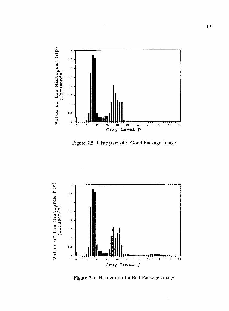
histogram in Figure 2.6 between h(p)=0 and h(p)=600 into
Figure 2.7. Three "valleys" are found around p=3, p=14, and
p=30. Usually, the gray level at the bottom of the "valley"
will be chosen as threshold value t. Since we already know
from Figure 2.5 and Figure 2.6 that foil flaws contribute the
highest gray scale level, in this system, we choose t=30.
After thresholding, the
value of a pixel can be
represented by a single bit,
i.e., 1 for light; 0 forFigure 2.8 An Image after
dark. Figure 2.8 shows the Thresholding
image in Figure 2.4 after
thresholding. A foil flaw is very clearly detected.
2.5.3 SRI Algorithmm
It is possible to get wrong information from the pixel
array after thresholding. Sometimes light reflects from
another part of the package and there is a bright area but no
foil flaw. However, the shape of bright area in this case is
not a narrow line as in Figure 2.8. The SRI algorithm, a
simple and commonly used algorithm, can effectively
distinguish different shapes.
The SRI algorithm was developed at the Stanford Research
Institute in the late 1970's. Its input is a pixel array
whose values have been converted from gray level to binary,
that is, white and black. The output of the SRI algorithm is
15
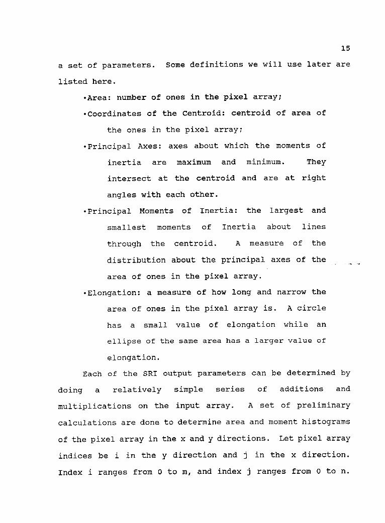
a set of parameters. Some definitions we will use later are
listed here.
-Area: number of ones in the pixel array;
Coordinates of the Centroid: centroid of area of
the ones in the pixel array;
-Principal Axes: axes about which the moments of
inertia are maximum and minimum. They
intersect at the centroid and are at right
angles with each other.
-Principal Moments of Inertia: the largest and
smallest moments of Inertia about lines
through the centroid. A measure of the
distribution about the principal axes of the
area of ones in the pixel array.
-Elongation: a measure of how long and narrow the
area of ones in the pixel array is. A circle
has a small value of elongation while an
ellipse of the same area has a larger value of
elongation.
Each of the SRI output parameters can be determined by
doing a relatively simple series of additions and
multiplications on the input array. A set of preliminary
calculations are done to determine area and moment histograms
of the pixel array in the x and y directions. Let pixel array
indices be i in the y direction and j in the x direction.
Index i ranges from 0 to m, and index j ranges from 0 to n.
16
The elements of the area histograms Ax and Ay in the x and y
directions respectively are calculated using the equations
below.
Ax(J)=Ep(i,J) (j=0,1,.,n) (1)i=0
Ay(i)=EP(1,j) (i=0,1,...,m) (2)
Here the term P(i,j) is the element of the pixel array in the
jth column and the ith row.
The elements of Mm, one of the moment histograms, are
calculated below.
iy,,(;)=E [(i+i)p(i,J)] (J=0,1, (3)i=0
Area is given by the equation below.
n
A=EA,(J)j=o
(4)
The coordinates of the centroid are given by the
equations below.
CX= Ai [(J+1)A(;)]0
m
Cy=1): [(i+1).Ay(i)]io-
(5)
(6)
The equation for elongation is based on moments of
17
inertia (a and c) and the product of inertia b about the
horizontal and vertical axes through the centroid. Equations
for these parameters are given below.
a={ E [ (J+1)2A,c(i)D-cx2A
b=2{ { 7 [(j +1)M,(j)1 } C,cCA}J=0
(7)
( 8 )
c={ E (1+1)2213,(i)])C72A (9)J=1
Elongation is given by the equation below.
E- 02+(a-c)2a+c
(10)
Using elongation, we can easily tell foil defects from
other reflections. If the image comes from a package with
foil flaws, E >= 0.9.
18
Chapter 3 Electrical and Mechanical Construction
3.1 Parallel Digital I/O Interface
Besides the vision system, there are also auxiliary
devices in the installation. Two main sections are conveyor
control and defective package rejection. Both of these
require interface to the control computer.
A MetraByte Data Acquisition and Control board is plugged
into an expansion slot in the computer. It provides 24
TTL/DTL compatible digital I/O lines, interrupt input and
enable lines and external connections to the IBM PC bus power
supplies(+5V, -5V, +12V, -12V). The 24 digital I/O lines are
provided through an 8255-5 programmable peripheral interface
(P.P.I.) divided into three ports, an 8 bit PA port, an 8 bit
PB port, and 8 bit PC port. The PC port may also be used as
two half ports of 4 bits, PC upper(PC 4-7) and PC lower(PC 0-
3). Each of the ports and half ports may be configured as an
input or an output by software control according to the
contents of a write only control register (see Figure 3.1) in
the P.P.I.
The 8255-5 P.P.I. uses 4 I/O address locations which are
fully decoded within the I/O address space of the IBM PC. The
base address is set by an 8 position DIP switch and can in
theory be placed anywhere in I/O address space. In our case,
19
CONTROL WORDD7 D6 D5 D4 D3 D2 131 DO
CONTROL WORDCONFIGURATION
0 -PCO-3 OUTPUT1 -PCO-3 INPUT
0 -PB OUTPUT1 -PB INPUT
0 -MODE 0 FOR PB/P03-31 -MODE 1 FOR PB/PCO-3
0 -PC4-7 OUTPUT1 -PC4-7 INPUT
0 -PA OUTPUT1 -PA INPUT
00 -MODE 0 FOR PA/PC4-701 -MODE 1 FOR PA/PC4-710 (OR 11) MODE 2 FOR PA/PC4-7
0 -BIT SET/RESET MODE1 -MODE SET ACTIVE
Figure 3.1 Write-only Control Register(Courtesy of MetraByte Corporation)
the base address is set at 280 hexadecimal (see Figure 3.2).
The address map for the P.P.I. register is shown in Figure
3.3.
BASE ADDRESS
ON
f x xx x x x
9 7 6 5 4 3DECIMAL
EQUIVALENT2 ADDRESS
A2 4A3 8
16A4AS
64A6128A7256A8512A9
*Switchs have decimal values as above in the "OFFposition. In the "ON" position decimal value is zero.
Figure 3.2 Base Address Switch Setting for 280 HEX(Courtesy of MetraByte Corporation)
20
Base Address + 0 PA port read/write
Base Address + 1 PB port read/write
Base Address + 2 PC port read/write
Base Address + 3 Control write only
Figure 3.3 Address Map for P.P.I. Register(Courtesy of MetraByte Corporation)
3.2 Conveyor Control
A conveyor control block diagram is shown in Figure 3.4.
The computer sends a signal through the parallel digital-I /O
interface to turn on the conveyor motor. The shaft of the
motor is connected to an incremental optical encoder. The
encoder is connected to a counter which can be read by the
computer through the parallel digital I/O interface.
Computer
Encoder CounterCircuit and I/OInterface
I/O Interface
Conveyor Motor
Encoder
Figure 3.4 Conveyor Motor Control
MechanicalConnection
21
3.2.1 Motor Control
An optically isolated I/O mounting rack made by OPTO -22
is used to control the conveyor motor. All eight positions of
the optically isolated I/O mounting rack may be utilized as
either inputs or outputs. The input modules must have a
positive DC voltage (3 - 32V) and DC return applied to the
terminals to activate them (see Figure 3.5b). Positive
voltage should be applied to the odd numbered terminal and
ground to the even numbered terminal. When wiring the output
modules to control a load, positive voltage is applied to the
odd numbered terminal and the load to the even numbered
terminal (see Figure 3.5a). The terminals can be asserted by
cabling the power modules to the parallel digital I/O
interface mounted in the computer. Making computer output
high will turn on the load.
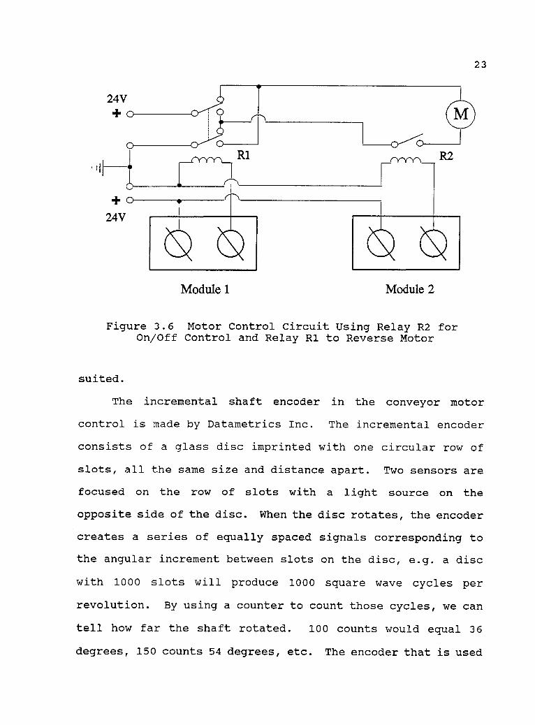
In conveyor motor control, two output modules and two
relays are used as shown in Figure 3.6. When output module 2
is off the motor stops. When output module 2 is on the motor
runs. If output module 1 is on the motor rotates clockwise;
if output module 1 is off the motor rotates counter-clockwise.
3.2.2 Incremental Shaft Encoder
Another important element is the optical encoder which
measures how far the conveyor moves. Optical encoders can be
classified into two types: incremental and absolute position
encoders. Each has specific applications for which it is best
22
I/OModuleBarrier
Strip
Odd No.
`20
DC Power
/ Even No.
I/OModuleBarrier
Strip
Odd No.
(a) Output
DC Power
Load
o/O
Even No.
(b) Input
Grip,Motor,Light,etc.
Switch,Relay,etc.
Figure 3.5 Example of Optically Isolated I/O Connections(Courtesy of Microbot, Inc.)
24V+o
0+o
24V
o_____CYYY-1_ R1
23
N NModule 1 Module 2
Figure 3.6 Motor Control Circuit Using Relay R2 forOn/Off Control and Relay R1 to Reverse Motor
suited.
The incremental shaft encoder in the conveyor motor
control is made by Datametrics Inc. The incremental encoder
consists of a glass disc imprinted with one circular row of
slots, all the same size and distance apart. Two sensors are
focused on the row of slots with a light source on the
opposite side of the disc. When the disc rotates, the encoder
creates a series of equally spaced signals corresponding to
the angular increment between slots on the disc, e.g. a disc
with 1000 slots will produce 1000 square wave cycles per
revolution. By using a counter to count those cycles, we can
tell how far the shaft rotated. 100 counts would equal 36
degrees, 150 counts 54 degrees, etc. The encoder that is used
24
provides only 50 cycles per revolution. However this
resolution is high enough in this application.
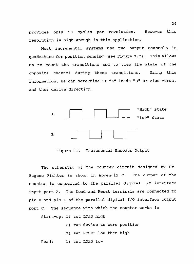
Most incremental systems use two output channels in
quadrature for position sensing (see Figure 3.7). This allows
us to count the transitions and to view the state of the
opposite channel during these transitions. Using this
information, we can determine if "A" leads "B" or vice versa,
and thus derive direction.
A
B
"High" State
"Low" State
Figure 3.7 Incremental Encoder Output
The schematic of the counter circuit designed by Dr.
Eugene Fichter is shown in Appendix C. The output of the
counter is connected to the parallel digital I/O interface
input port A. The Load and Reset terminals are connected to
pin 0 and pin 1 of the parallel digital I/O interface output
port C. The sequence with which the counter works is
Start-up: 1) set LOAD high
2) run device to zero position
3) set RESET low then high
Read: 1) set LOAD low
25
2) read input port
3) set LOAD high
This counter can count up to 255 cycles.
3.3 Defective Package Rejection
After image processing, the computer can determine
whether the package inspected is good or has foil flaws. As
soon as a defective package is found, the computer will send
a signal through the parallel digital I/O interface to pin 6
of output port B, thus module 3 of the optically isolated I/O
mounting rack will be turned on and a rotary solenoid (Ledex
Inc.) is energized.
A drawing of the diversion gate is shown in Figure 3.8.
When the rotary solenoid is energized, the shaft turns 22°.
The defective package will be pushed off the conveyor.
Solenoid
c
<Conveyor
Package
Figure 3.8 Diversion Gate
26
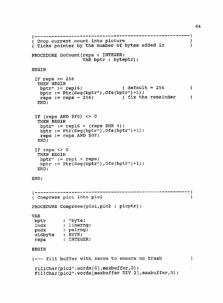
Chapter 4 Software
The software is written in QuickC and Turbo Pascal. The
main program "INSPECT" calls four functions (QuickC) and one
program (Turbo Pascal). The flow chart of "INSPECT" is shown
in Figure 4.1, and program code is in Appendix A. Four
functions and one Pascal program are introduced as follows.
4.1 Function Initialization
The function Initialization sets up parallel digital I/O
interface port addresses, and control port states, resets the
conveyor motor to off and the incremental encoder counter to
0. It prompts the user to enter thresholding level and
elongation criterion, and returns an value that tells the main
program to keep running or to stop.
4.2 Function Conveyor
The function conveyor always turns the conveyor motor on
first, moves inspected package out of the inspection area, and
sends a new package into the inspection area. Then it sets
the diversion door open or closed depending on an input value
from main program. While the motor runs, the program reads
encoder counter input repeatedly accumulating a total encoder
count. When the count reaches 768, the computer turns the
27
Call Function Initialization
Set D True and
Run System?
Is D True? Close Gate
Call Function Conveyor
Open Gate
Call Program Vision
Call Function Histogram
Call Function Elong
Elongation < Criterion
Set D True
Set D False
Continue Running?
Figure 4.1 Flow Chart of Program INSPECT
28
motor off.
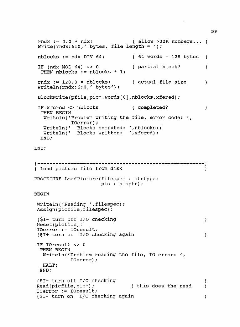
4.3 Program Vision
The procedures that capture and expand digitized pictures
created by the digitizer board are supplied by the Circuit
Cellar Inc. with the ImageWise Digitizer. Since these
procedures are written in Turbo Pascal, the program Vision has
to use the same language. It is mainly used to call these
procedures so that the image can be captured and expanded, and
then saved into the file "PACKAGE.DAT".
4.4 Function Histogram
This function is used to show a histogram of the image.
It is not necessary for system operation, but is very useful
for the user to choose thresholding value.
4.5 Function Elong
Function Elong has two tasks. One is thresholding; the
other is calculating elongation. It reads image pixel values
from data file "PACKAGE.DAT", then performs thresholding. The
thresholding level is an input variable. After thresholding,
it calculate Area (the number of l's in the pixel array). If
Area is equal to 0, the package will be accepted. Otherwise
it calculates and returns elongation. If this value is
greater than elongation criterion, the package inspected is
identified as a defective product.
29
Chapter 5 Testing and Conclusion
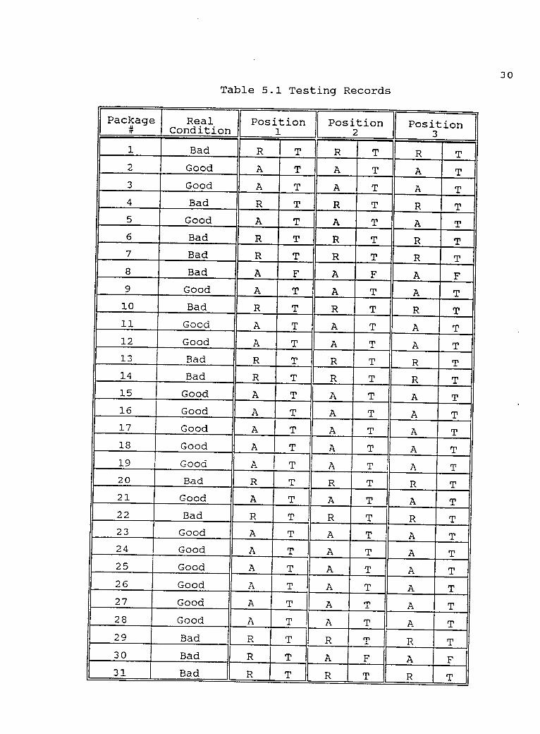
5.1 Testing Results
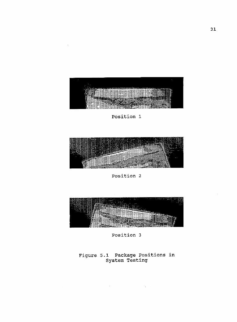
31 packages were tested in different positions. The
results are listed in Table 5.1. Position 1, 2, and 3 are
shown in Figure 5.1. The left columns under the position 1,
2, and 3 show "A" if the inspection system accepts the
packages, or "R" if it rejects the packages. The right column
shows "T" if the vision system accepts a good package or
rejects a bad package, and "F" if it accepts a bad package or
rejects a good package. If accuracy is defined as
The number of samples The number of FlsA- 100%,The number of Samples
we can calculate accuracies of testing with different package
positions 1, 2, and 3
A,- 311 1 100%=96.77% (Position 1) ;3
A2 3131-2 100%=93.55% (Position2) ;
-A,- 311 2 100%=93.55% (Position 3);- 3
and total accuracy
30
Table 5.1 Testing Records
Package#
RealCondition
Position1
Position2
Position3
1 Bad R T R T R T2 Good A T A T A T3 Good A T A T A T4 Bad R T R T R T5 Good A T A T A T6 Bad R T R T R T7 Bad R T R T R T8 Bad A F A F A F9 Good A T A T A T10 Bad R T R T R T11 Good A T A T A T12 Good A T A T A T13 Bad R T R T R T14 Bad R T R T R T15 Good A T A T A T16 Good A T A T A T17 Good A T A T A T18 Good A T A T A T19 Good A T A T A T20 Bad R T R T R T21 Good A T A T A T22 Bad R T R T R T23 Good A T A T A T24 Good A T A T A T25 Good A T A T A T26 Good A T A T A T27 Good A T A T A T28 Good A T A T A T29 Bad R T R T R T30 Bad R T A F A F31 Bad R T R T R T
31
1 i;JI
4111,..1 :t ,.; .., ,!"11 f,
64.41PIO* \ s
: II
{. ,gt,' '41 % :411
111.'4n' Altai vh
Position 1
Position 2
Position 3
Figure 5.1 Package Positions inSystem Testing
32
31x3 -(1 +2 +2)100% = 94.62 %.100%=94.62%.
31x3
This accuracy is not satisfactory. But all
classification errors occur with only two bad packages that
were accepted by the inspection system. Since there is a much
greater proportion of good packages in a real system than in
our sample population, the accuracy in real system will be
much better than in this experiment.
The classification errors could have been predicted by
examination of the packages. Package 8 has a very narrow foil
line, and package 30 has many wrinkles on the foil line. One
way to correct these errors is to reduce the threshold value
t. However, the risk of rejecting good packages will rise.
An ideal system should minimize both types of errors, i.e.,
rejecting good packages and accepting bad packages.
5.2 Future Expansion
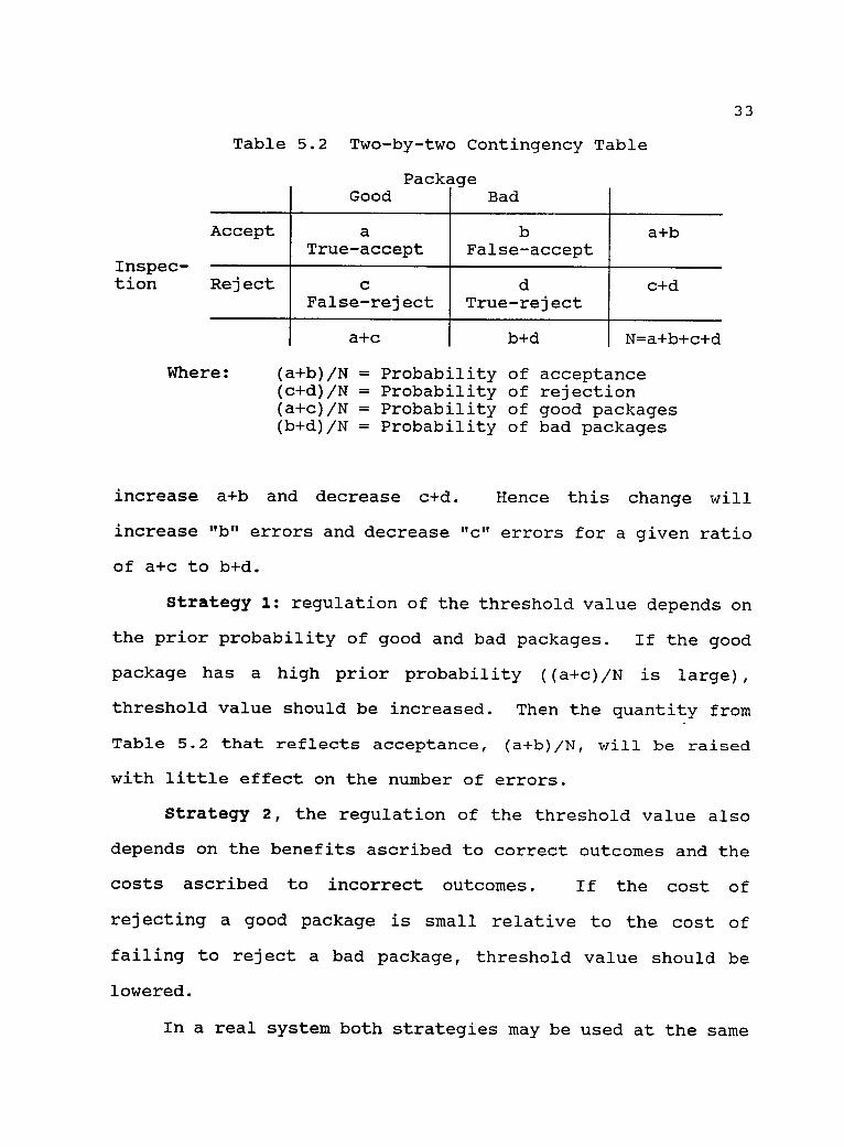
With two alternative package conditions (good and bad)
and two inspection diagnostic alternatives (accept and
reject), data are arranged in a two-by-two contingency table
(see Table 5.2)(187. The "b" in this table corresponds to the
first type of error accepting bad packages, and the "c"
corresponds to the second type of error rejecting good
packages. Minimizing both types of errors may be realized by
optimizing threshold value. Increasing threshold value will
33
Inspec-tion
Table 5.2 Two-by-two Contingency Table
PackageGood Bad
Accept aTrue-accept
bFalse-accept
a+b
Reject cFalse-reject
dTrue-reject
c+d
a+c b+d N=a+b+c+d
Where: (a+b)/N = Probability of acceptance(c+d)/N = Probability of rejection(a+c)/N = Probability of good packages(b+d)/N = Probability of bad packages
increase a+b and decrease c+d. Hence this change will
increase "b" errors and decrease "c" errors for a given ratio
of a+c to b+d.
Strategy 1: regulation of the threshold value depends on
the prior probability of good and bad packages. If the good
package has a high prior probability ((a+c)/N is large),
threshold value should be increased. Then the quantity from
Table 5.2 that reflects acceptance, (a+b)/N, will be raised
with little effect on the number of errors.
Strategy 2, the regulation of the threshold value also
depends on the benefits ascribed to correct outcomes and the
costs ascribed to incorrect outcomes. If the cost of
rejecting a good package is small relative to the cost of
failing to reject a bad package, threshold value should be
lowered.
In a real system both strategies may be used at the same
34
time.
A better way of regulating threshold value is adaptive
control. Since environmental conditions change with time,
even though we find the optimal threshold value in static
state, it may not be best over all time. During the
processing, as long as a bad package appears, adjusting the
threshold value according to the bottom value of the "valley"
in the histogram as well as the strategies that are discussed
above will result in dynamic threshold value optimization.
5.3 Conclusion
This work combined many different techniques including
image processing, computer interfacing, electrical and
mechanical technology, and then applied them in manufacturing.
The most important section is machine vision. This work
shows: 1)How machine vision can be used in quality control;
2)Modern manufacturing development needs to synthesize
knowledge of many fields.
Before this work is applied in industry, it needs to be
modified further. The most obvious shortcoming is the long
process cycle of up to 31 seconds. The main reason is that
ImageWise digitizer transfers image data to the computer over
a serial interface. The part of the process from capturing a
picture to saving it on hard disc takes 23 seconds. So,
parallel data transmission interface is essential in a real
production assembly line.
35
Bibliography
[1] Eugene Fichter, "Simulation of the SRI VisionAlgorithm on a Microcomputer", Proceedings,International Computers in Engineering Conference andExhibition, 20-24 July, 1986, Chicago, IL, Vol. 3, pp.83-88.
[2] Nello Zuech and Richard K. Miller, "Machine Vision",Lilburn, GA: The Fairmont Press, 1987.
[3] Don Braggins and Jack Hollingum, "The Machine VisionSourcebook", IFS (Publications Ltd, UK: Springer- NAmd.ac1986.
[4] E. W. Kent and M. 0. Shneier, "Eyers for Automations",IEEE Spectrum, Vol. 23, No. 3, Mar. 1986, pp. 37-45.
[5] Azriel Rosenfeld, "Introduction to Machine Vision",IEEE Control Systems Magazine, Vol. 5, No. 3, Aug.1985, pp. 14-17.
[6] Wesley E. Snyder, "Industrial Robots: ComputerInterfacing and Control", Englewood Cliffs, NJ:Prentice-Hall, 1985.
[8] 0. D. Faugeras, "Fundamentals in Computer Vision AnAdvanced Course", Cambridge, UK: Cambridge UniversityPress, 1983.
[9] Dana H. Ballard and Christopher M. Brown, "ComputerVision", Englewood Cliffs, NJ: Prentice-Hall, 1982.
[10] David Marr, "Vision - A Computational Investigationinto the Human Representation and Processing of VisualInformation", San Francisco, CA: Freeman, 1982.
[11] Theo Pavlidis, "Algrorithms for Graphics and ImageProcessing", Rockville, MD: Computer Science Press,1982.
/* This program is created for "Package Inspection *//* with a Machine Vision System ". It consists of four *//* functions written by Quick C. It senses the encoder *//* and control the conveyor motor. After calling a *//* Pascal program VISION from DOS shell and getting *//* image data of a package, it makes a decision to set *//* the gate open or closed. *//**********************************************************/
# include <stdio.h># include <conio.h># include <math.h># include <process.h>
main(){
/* FUNCTION DECLARATIONS */char initialization(int *threshLevel, float
/* VARIABLE DECLARATIONS */int threshLevel; /* Threshholding Level */int door; /* Flag for Gate Position */char flag; /* Flag for Program Control */float elongLevel; /* Elongation Level */float elongation; /* Elongation Value */
/* PROGRAM CODE */flag = initialization(&threshLevel, &elongLevel);
/* Initialization */door = 1; /* Set the Gate Open */
while ((flag != 'q') && (flag != 'Q')){
conveyor(door); /* Run the Conveyor */
}
}
38
conveyor(door); /* Run the Conveyor */
spawnle(P_WAIT, "vision.com",NULL);/* Capture a Picture */
/* DEFINE CONSTANTS */unsigned int turnoff=OxF6; /* Value for Turning Off
the Conveyor *//* SET INPUT AND OUTPUT PORTS' ADDRESSES */unsigned int pio=0x280; /* Parallel IO Base Address */unsigned int porta=pio; /* Port A Address */unsigned int portb=pio+1; /* Port B Address */unsigned int portc=pio+2; /* Port C Address */unsigned int ctrlpio=pio+3; /* Control Port Address */
/* PIO SETUP CONSTANTS */
39
unsigned int portain=0x10, portbin=0x2;unsigned int portcin=0x9, modeset=0x80;unsigned int portaout=0, portbout=0, portcout=0;
/* DECLARE VARIABLES */char flag;w /* Flag for Program Control */
/* PROGRAM CODE *//* SET CONTROL PORT */outp(ctrlpio, portain portcout portbout modeset);/* RESET MOTOR */outp(portb, turnoff); /* Turn Off the Motor *//* RESET ENCODER */outp(portc, 3); /* set LOAD high and RESET high */outp(portc, 2); /* set LOAD high and RESET low */outp(portc, 3); /* set LOAD high and RESET high */printf("Start to run the system? (y/n) \n");flag = getche();if (flag == 'y' JJ flag == 'Y')
printf("\nPlease enter thresholding level (0-63): ");scanf("%d", &(*threshLevel));printf("\nPlease enter elongation level (0.0-1.0): ");scanf("%f", &(*elongLevel));
/* Function Conveyor always turns the conveyor motor on *//* first, moves inspected package out of the inspection *//* area and sends a new package into the inspection */
/* area. At meantime it sets the diversion gate open or *//* closed depending on an input value from main program.*//* During the motor running, it reads encoder counter */
/* inputs continuously. As soon as the number of wave */
/* cycles reaches, it turns the motor off. *//**********************************************************/
void conveyor(door)int door;
/* DEFINE CONSTANTS */unsigned int turnoff=OxF6; /* Value for Turning Off
the Conveyor *//* SET INPUT AND OUTPUT PORTS' ADDRESSES */unsigned int pio=0x280; /* Parallel IO Base Address */unsigned int porta=pio;unsigned int portb=pio+1;unsigned int portc=pio+2;
/* Port A/* Port B/* Port C
Address */Address */Address */
/* PIO SETUP CONSTANTS */unsigned int portain=0x10, portbin=0x2;unsigned int portcin=0x9, modeset=0x80;unsigned int portaout=0, portbout=0, portcout=0;
/* DECLARE VARIABLES */unsigned int outval;
unsigned int encodata;unsigned int count;unsigned int preval;char valve;
40
/* Value for Controllingthe Motor, and the Gate */
/* Value Read from the Encoder *//* Encoder Rotation Count *//* Last Value of encodata */
/* Flag for Running orStopping the Motor */
/* PROGRAM CODE *//* SET THE GATE POSITION */if (door == 1)
outval = OxF2; /* Turn on the Conveyor Motor */else /* and Set the Gate Open */
outval = 0x02; /* Turn on the Vonveyor Motor *//* and Set the Gate Closed */
/* DECLARE VARIABLES */float maxval; /* The Largest Bin Value */float maxvall; /* The Next Largest Bin */float barstep; /* Height of Steps */float halfstep; /* Half of Barstep */float histo[64]; /* Histogram Value */float barbase; /* Bottom of Bar */float barmid;char ch;int i, j, flag;
/* Show Histogram on the Screen */for (j = maxbar; j >= 1; j--)
barbase = (float)(int)(barstep * j);barmid = barbase + halfstep;printf("%6.0f", barbase);for (i = 0; i <= 63; i++) /* Show in Each Line */{
if (histo[i] > barmid) printf("%c", barchar);else if (histo[i] > barbase) printf("%c",halfbar);
else printf("_");}printf("\n");
printf(" O");for (i = 0; i <= 63; i++) /* Show in Bottom */
if (histo[i] > halfstep) printf("%c", barchar);else if (histo[i] > 0.0) printf("%c", halfbar);
else printf("_");
printf("\n");
/* Show coordinate */printf(" O");for (i = 1; i <= 6; i++)
printf(" %d", i) ;printf("\n");printf(" 11);.
for (i = 0; i <= 5; i++)for (j = 0; j <= 9; j++)
printf("%d", j);printf("0123\n");
}
/**********************************************************//* Function Elong has two tasks. One is thresholding; */
/* the other is calculating image's elongation. It */
/* reads image pixels's value from a data file */
/* "PACKAGE.DAT", then processes thresholding. */
/* Thresholding level is an input variable translated */
/* from main program. After thresholding, it calculates */
/* image's elongation, then return elongation value to *//* main program. *//**********************************************************/
43
float elong(level)char level;{
/* DECLARE FILE POINTER */FILE *fp;
/* DECLARE VARIABLES */char pixel[81][256]; /* Array of Pixels' Gray Scale */unsigned int area_x[256]; /* Area Histograms in x
Direction */unsigned int area_y[81]; /* Area Histograms in y
Direction */unsigned int moment_x[256]; /* Moment Histograms in x
Direction */unsigned int i, j;unsigned long int n;float inertia_a;float inertia_b;float inertiac;float elongation;float coordinate_x;float coordinate_y;char ch;
/* Area: Number of Ones *//* Moments of Inertia *//* Product of Inertia *//* Moments of Inertia */
/* Elongation *//* Coordinate in x Direction *//* Coordinate in y Direction */
THEN BEGINtempval := intval XOR $FFFF; { l's compl }
tempval := tempval DIV 4096; { bits to LSD }
tempval := tempval XOR $000F; { flip again }
tempstring[1] := NybToHex(tempval); { now convert }
ENDELSE BEGIN { >= 0, simple convert }
tempstring[1] := NybToHex((intval AND $F000) DIV 4096);
END;
{--- the rest are easy
tempstring[2] := NybToHex((intval AND $0F00) DIV 256);tempstring[3] := NybToHex((intval AND $00F0) DIV 16);tempstring[4] := NybToHex( intval AND $000F);
IntToHex := tempstring;
END;
}
{ converts byte to characters
FUNCTION ByteToHex(intval:INTEGER) : Hextype;
VARtempstring : Hextype;
BEGIN
}
52
53
tempstring :=
tempstring[1]tempstring[2]
'00';
:= NybToHex((intval AND $00F0) DIV 16);:= NybToHex( intval AND $000F);
{ Get a picture from the transmitter{ The bit rate depends on which PC you're using...{ An 8 MHz AT can handle 28.8 K bits/sec{ Sets RTS and DTR to switch the relay box before( taking the picture, restores normal display after{ Some debugging statements are commented out... you( may need them to get your system running
PROCEDURE GetPicture(pic : picptr;resol : BYTE);
VARpicbyte : BYTE;bptr : byteptr;
BEGIN
}
{ byte from transmitter }( fake pointer to pic )
Port[comMCR] := $03; ( PC <-> trans serial{ camera -> monitor
Delay(200); { pause to stabilize
(*Write('Waiting for key press...');Readln;
*)
))
)
bptr := Ptr(Seg(picA),Ofs(picA)-1); { preset for loop )
(*Writeln('KeyPressed is: ',KeyPressed);Writeln('port end is: ',(Port[comdata]= fldend));
bptr := Ptr(Seg(picA),Ofs(picA)-1); { set byte ptr
REPEAT { for each linebptr := Ptr(Seg(bptrA),Ofs(bptrA)+1); { tick ptrWHILE (Port[comdata] = XOFF) AND NOT KeyPressed DO;WHILE ((Port[comLSR] AND THRE) = 0) AND
NOT KeyPressed DO; { stall for dataPort[comdata] := bptrA; { send the byte
UNTIL (bptrA = fidend) OR KeyPressed;
END;
}
)
)
)
)
))
)}
( )
{ Set up frame and line syncs in a buffer }
{ This should be done only in freshly allocated buffers }
PROCEDURE SetSyncs(picl : picptr);
VARlndx : linerng; { index into lines
BEGIN
piclA.fmt.syncF := fieldsync; ( set up empty picture
)
)
60
FOR lndx := 0 TO maxline DO BEGINpicIA.fmt.lines[lndx).syncL := linesync;FillChar(piclA.fmt.lines[lndx].pels[0],maxpel+1,0);
Writeln;Writeln('Surprise at having found field end!');
END;ELSE BEGINCASE (bptrA AND $F0) OF$00..$3F : BEGIN
pic2A.fmt.lines[lndx].pels[pndx] := bptrA;oldbyte := bptrA;IF pndx < maxpelTHEN BEGINpndx := pndx + 1;IF overflowTHEN BEGINWrite('Too much data on line ',lndx:3);Writeln(' pel data ',ByteToHex(bptrA));errcount := Succ(errcount);
END;ENDELSE BEGINpndx := 0;overflow := TRUE;
END;Writeln('Data: ',ByteToHex(bptrA)); *)
END;repl : BEGIN
FOR reps := 1 TO (bptrA AND $0F) DO BEGINpic2A.fmt.lines[lndx].pels[pndx] := oldbyte;IF pndx < maxpelTHEN BEGINpndx := pndx + 1;IF overflowTHEN BEGINWrite('Too much data on line ',lndx:3);Writeln(' lx rep ',ByteToHex(bptrA));errcount := Succ(errcount);pndx := 0; *)END
ENDELSE BEGINpndx := 0;overflow := TRUE;
63
END;Writeln('Repl: ',ByteToHex(bptrA)); *)
END;END;
rep16 : BEGINFOR reps := 1 TO (16 * (bptrA AND $0F)) DO BEGINpic2A.fmt.lines[lndx].pels[pndx] := oldbyte;IF pndx < maxpelTHEN BEGINpndx := pndx + 1;IF overflowTHEN BEGINWrite('Too much data on line ',lndx:3);Writeln(' 16x rep ',ByteToHex(bptrA));errcount := Succ(errcount);
IF reps > 1THEN DoCount(reps,bptr); { n reps, send count }
IF reps = 1 { 1 rep, copy old byteTHEN BEGINbptrA := oldbyte;bptr := Ptr(Seg(bptrA),Ofs(bptrA)+1); { step ptr }
END;
bptrA := 0;
(*Write('.'); *)
END;
{ force trailer zero
bptrA := fldend; { flag the endingWriteln;
END;
}
)
65
66
Appendix C Shaft Encoder Counter Circuit
encoder A
encoder B
+V
100K0
100K0
74C14pin
7 _L1113 --1014 --19 +V
15
3 4
74C14
Cl
Cuc Q1
Q2U/D Q3
Q44516
+V
ID GodCO
7
15
10
CI
CLK Q1Q2
U/D Q3Q4
4516
611 5
22
+16
V
13
D1 Q1
02 Q2D9 43D4 Q4
74C175
+V1
CIE -i-V
CLK Gn49
0
10 215 3
S
11 514 22
+V +V
GndT+V
13
DI Q1Q2
D3 Q3D4 Q4
74CI76
CLR +V
a
7
Gncli
16
Protocol NotesStartup: 1 set LOAD high
2 run device to zero position3 set RESET low then high
Read: 1 set LOAD low2 read input port3 set LOAD high
Eugene Fichter28 Sept 1989
1 low is ground potential; high is -i-V2 +V is CMOS positive supply range3 LOAD latches data to read on falling edge4 RESET sets counter to zero when pulsed low