Progress In Electromagnetics Research, PIER 83, 93–106, 2008 AN ACCURATE METHOD FOR IMPEDANCE MEASUREMENT OF RFID TAG ANTENNA S.-K. Kuo, S.-L. Chen, and C.-T. Lin Steel and Aluminum Research and Development Department China Steel Corporation Hsiao Kang, Kaoshiung 81233, Taiwan Abstract—This paper presents a method of antenna impedance measurement for RFID tag antenna based on a differential probe. The importance of accurate impedance measurement in optimal design of tag antenna, especially for the metal tags, is first addressed. Afterwards, an overview of the existing methods based on the single- ended probe and the balun probe is presented. The proposed method using the differential probe is explained based the well-known two port network model. Experiments for both balanced and unbalanced tag antenna measurement demonstrate the differential probe can provided better agreement with simulated results. 1. INTRODUCTION RFID has been an emerging research issue in recent years. Many research topics have been studied in recent investigations, including reader antenna design [1], interference and collision problems [2, 3], as well as tag design. Because of the interference problem, achieving a successful application of RFID technology in metal industry relies heavily on the design of tag antenna. Many metal tags, such as patch [4–6], inverted-F [7,8] and loop [9], were designed in the past few years. In order to have low profile, these metal tags usually have a “sandwich type” structure, in which a dielectric layer is placed between the bottom ground plane and the upper plate with an antenna pattern. Tag performance relies heavily on two factors, antenna gain and impedance matching [10]. Because of the insufficient bandwidth and low gain characteristics [11], accomplishing accurate impedance matching is therefore very critical for metal tags, which becomes the key factor in determining the performance. Therefore, the requirement of iterated dimension adjustment during the course of optimal antenna
Transcript
Progress In Electromagnetics Research, PIER 83, 93–106, 2008
AN ACCURATE METHOD FOR IMPEDANCEMEASUREMENT OF RFID TAG ANTENNA
S.-K. Kuo, S.-L. Chen, and C.-T. Lin
Steel and Aluminum Research and Development DepartmentChina Steel CorporationHsiao Kang, Kaoshiung 81233, Taiwan
Abstract—This paper presents a method of antenna impedancemeasurement for RFID tag antenna based on a differential probe.The importance of accurate impedance measurement in optimal designof tag antenna, especially for the metal tags, is first addressed.Afterwards, an overview of the existing methods based on the single-ended probe and the balun probe is presented. The proposed methodusing the differential probe is explained based the well-known two portnetwork model. Experiments for both balanced and unbalanced tagantenna measurement demonstrate the differential probe can providedbetter agreement with simulated results.
1. INTRODUCTION
RFID has been an emerging research issue in recent years. Manyresearch topics have been studied in recent investigations, includingreader antenna design [1], interference and collision problems [2, 3],as well as tag design. Because of the interference problem, achievinga successful application of RFID technology in metal industry reliesheavily on the design of tag antenna. Many metal tags, such aspatch [4–6], inverted-F [7, 8] and loop [9], were designed in the pastfew years. In order to have low profile, these metal tags usuallyhave a “sandwich type” structure, in which a dielectric layer is placedbetween the bottom ground plane and the upper plate with an antennapattern. Tag performance relies heavily on two factors, antenna gainand impedance matching [10]. Because of the insufficient bandwidthand low gain characteristics [11], accomplishing accurate impedancematching is therefore very critical for metal tags, which becomes thekey factor in determining the performance. Therefore, the requirementof iterated dimension adjustment during the course of optimal antenna
94 Kuo, Chen, and Lin
design highlights the importance of accurate impedance measurement.This paper presents a method for accurate impedance measurementbased on a differential probe. Section 2 introduces two existingmethods employed for tag antenna measurement. The differentialprobe with its two-port network model is discussed in Section 3.Section 4 demonstrates the probe is able to delivers better accuracythan the two well-known techniques for both balanced and unbalancedtype of tag antenna. Finally, conclusions are drawn in Section 5.
2. EXISTING METHODS FOR RFID ANTENNAIMPEDANCE MEASUREMENT
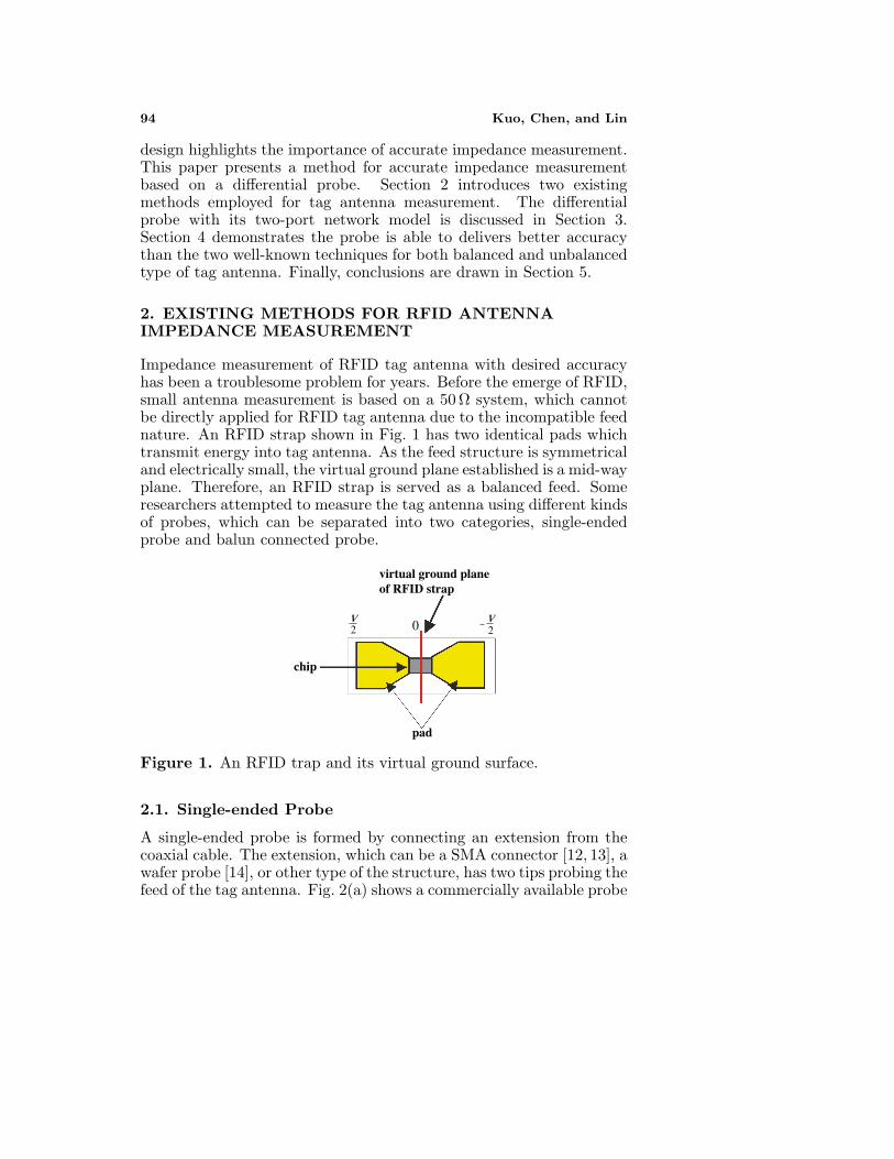
Impedance measurement of RFID tag antenna with desired accuracyhas been a troublesome problem for years. Before the emerge of RFID,small antenna measurement is based on a 50 Ω system, which cannotbe directly applied for RFID tag antenna due to the incompatible feednature. An RFID strap shown in Fig. 1 has two identical pads whichtransmit energy into tag antenna. As the feed structure is symmetricaland electrically small, the virtual ground plane established is a mid-wayplane. Therefore, an RFID strap is served as a balanced feed. Someresearchers attempted to measure the tag antenna using different kindsof probes, which can be separated into two categories, single-endedprobe and balun connected probe.
virtual ground planeof RFID strap
chip
pad
v2
v20
Figure 1. An RFID trap and its virtual ground surface.
2.1. Single-ended Probe
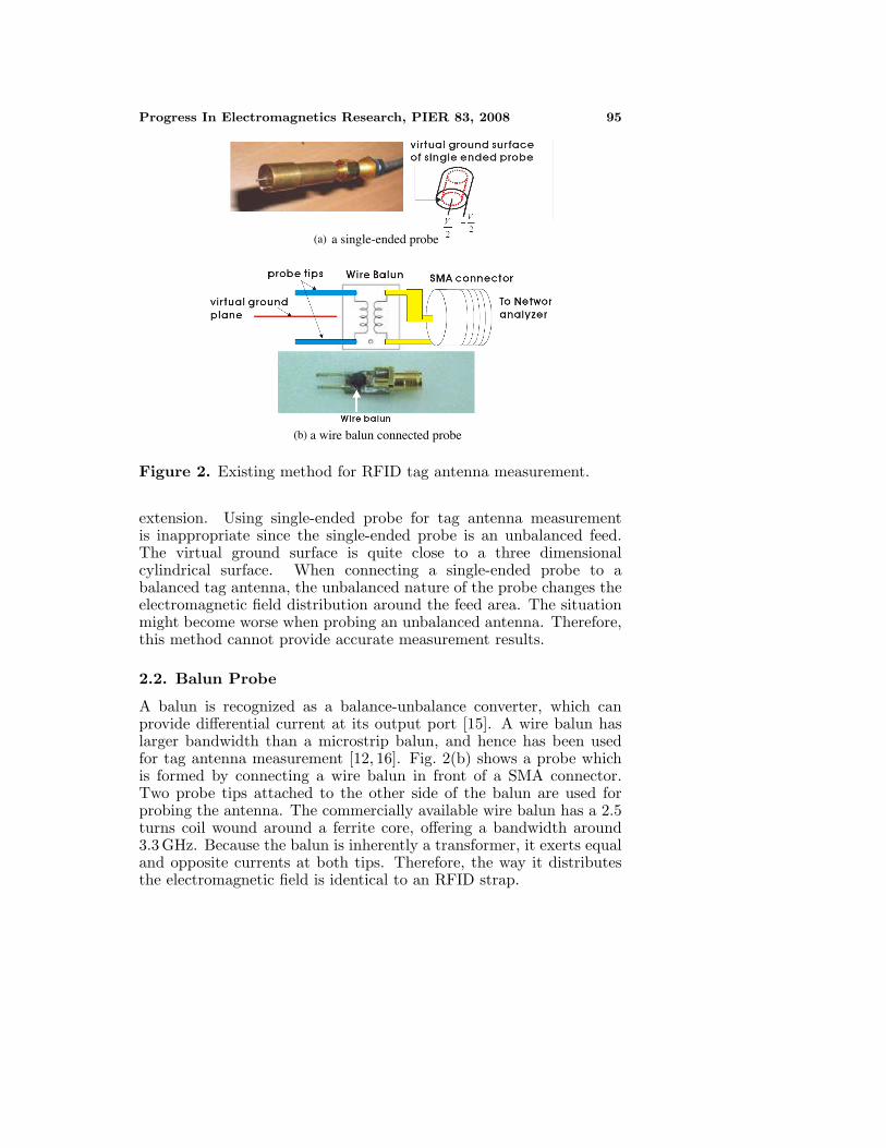
A single-ended probe is formed by connecting an extension from thecoaxial cable. The extension, which can be a SMA connector [12, 13], awafer probe [14], or other type of the structure, has two tips probing thefeed of the tag antenna. Fig. 2(a) shows a commercially available probe
Progress In Electromagnetics Research, PIER 83, 2008 95
(a)
(b)
a single-ended probe
a wire balun connected probe
Figure 2. Existing method for RFID tag antenna measurement.
extension. Using single-ended probe for tag antenna measurementis inappropriate since the single-ended probe is an unbalanced feed.The virtual ground surface is quite close to a three dimensionalcylindrical surface. When connecting a single-ended probe to abalanced tag antenna, the unbalanced nature of the probe changes theelectromagnetic field distribution around the feed area. The situationmight become worse when probing an unbalanced antenna. Therefore,this method cannot provide accurate measurement results.
2.2. Balun Probe
A balun is recognized as a balance-unbalance converter, which canprovide differential current at its output port [15]. A wire balun haslarger bandwidth than a microstrip balun, and hence has been usedfor tag antenna measurement [12, 16]. Fig. 2(b) shows a probe whichis formed by connecting a wire balun in front of a SMA connector.Two probe tips attached to the other side of the balun are used forprobing the antenna. The commercially available wire balun has a 2.5turns coil wound around a ferrite core, offering a bandwidth around3.3 GHz. Because the balun is inherently a transformer, it exerts equaland opposite currents at both tips. Therefore, the way it distributesthe electromagnetic field is identical to an RFID strap.
96 Kuo, Chen, and Lin
3. DIFFERENTIAL PROBE AND ITS TWO-PORTNETWORK MODEL
A differential probe proposed by Palmer et al., has a symmetricalstructure, and hence was employed to measure a balanced antenna [17].It is formed by combining two ports using a fixture as shown in Fig. 3,with the metal shield of the coaxial cables connected together to bethe common ground.
virtualground plane
Figure 3. A differential probe and its virtual ground plane.
For the purpose of calibration, a short wire is extended from theground as seen in Fig. 3. Performing full two-port “SOLT” (short-open-load-through) calibration establishes a calibration plane at the probetips. Because the differential probe is basically a balanced device withits ground right in the middle of the two tips, it is appropriate fortag antenna measurement. A two-port π-network as shown in Fig. 4is used for modeling the antenna and the probe, in which differencebetween Za and Zb accounts for unbalance of the tag antenna.
Antenna
Za
Zc
Zb
V
V
1
2
1
2
differentialprobe
l
l
Figure 4. A two-port π-network model for the probe and antenna.
Progress In Electromagnetics Research, PIER 83, 2008 97
Antenna
Za
Zc
Zb
RFID strap l
v2
-
v2
Figure 5. Network model for RFID strap and tag antenna.
Figure 5 shows when the differential probe is replaced by a RFIDstrap, the impedance actually “seen” by the RFID chip becomes
ZANT = (Za + Zb)‖Zc (1)
In order to obtain Za, Zb and Zc, S-parameters S11, S12, S21 andS22 were obtained and then converted to Y -parameters. Afterward,Za, Zb and Zc can be calculated through following equations [17],
Za =1
Y22 + Y21(2a)
Zb =1
Y11 + Y21(2b)
Zc = − 1Y21
(2c)
Measurement result obtained by the approach mentioned aboveis accurate, but very time consuming as it needs to download a lotof data from the network analyzer for post-processing. On the otherhand, the network analyzer (HP5710B) being used is able to convertstandard parameters into mixed-mode parameters in real-time. Amongthe mixed-mode parameters, the differential mode parameter Sdd11
measures the return loss of the differential signal,
Sdd11 =b1 − b2
a1 − a2(3)
where a1 and a2 represents incident waves of port 1 and port 2, whileb1 and b2 are reflected waves [18].
98 Kuo, Chen, and Lin
Converting the measured scattering parameter into impedancegives
Zdd11 = 2Z01 + Sdd11
1 − Sdd11(4)
where Z0 is the characteristic impedance of the transmission cable [19].Substitute (3) into (4) gives
Zdd11 = 2Z0a1 − a2 + b1 − b2
a1 − a2 − b1 + b2(5)
Represent a1, a2, b1 and b2 by ai = Vi+Z0Ii√Z0
and bi = Vi−Z0Ii√Z0
, fori = 1, 2, the impedance Zdd11 is expressed as
Zdd11 = 2V1 − V2
I1 − I2(6)
(6) can be regarded as differential voltage, V1 − V2, divided by theaverage current through the load, I1−I2
2 .Since in differential mode measurement incident waves of both
ports has equal amplitude and opposite phase, i.e., a1 + a2 = 0, oneobtains
V1 + V2 + Z0(I1 + I2) = 0 (7)
Furthermore, the relation between voltages V1 and V2, and currents I1
and I2 in the two port network is described by a Z-matrix,
In case of a balanced antenna, in which Za = Zb, one can deriveZ11 = Z22 = Za‖(Za+Zc), and Z12 = Z21 = Z2
a/(2Za+Zc). Therefore,Zdd11 in (9) can be expressed explicitly as
Zdd11 =2ZcZa
2Za + Zc(10)
in which 2(Za + Z0) has been factored out from numerator anddenominator. It is observed that (10) is exactly the ZANT expressed
Progress In Electromagnetics Research, PIER 83, 2008 99
by (1) under the condition Za = Zb. Therefore, there would be nodifference for ZANT and Zdd11 when measuring a balanced antenna.From the above discussion, it is concluded that even with timeconsuming post-processing, ZANT gives accurate impedance for bothbalanced and unbalanced antennas. For a balanced antenna, Zdd11 ispreferred since it can be directly obtained from the network analyzerequipped with mixed-mode parameter conversion.
4. MEASUREMENT RESULTS
In order to demonstrate the differential probe and the associatedmethods discussed in Section 3 is suitable for both balanced andunbalanced antennas, measurement results of two kinds of metal tags,namely loop antenna and patch antenna, are presented in this section.For the purpose of comparison, impedance measured by the single-ended probe shown in Fig. 2(a) and the balun connected probe shownin Fig. 2(b) are also presented.
4.1. Measurement of Loop Antenna
Metal tag made by a vertical small loop has miniature size andadequate read range for applications for metallic objects [9]. A slimshape RFID tag formed by a loop surrounding FR4 substrate canbe attached to steel plate. Fig. 6(a) shows the tag has dimension59 × 4 × 1.6 mm3, which has 0.4 m read range when place right ontop of the metal surface. Fig. 6(b) shows the differential probe was
RFID chip
(a)
(b)
Figure 6. Measurement of a loop tag. (a) A loop antenna for metallicsurface, (b) Probing the antenna with the differential probe.
100 Kuo, Chen, and Lin
2.0 5.0
j5.0
j2.0
ZANT
ddllZ
Simulation
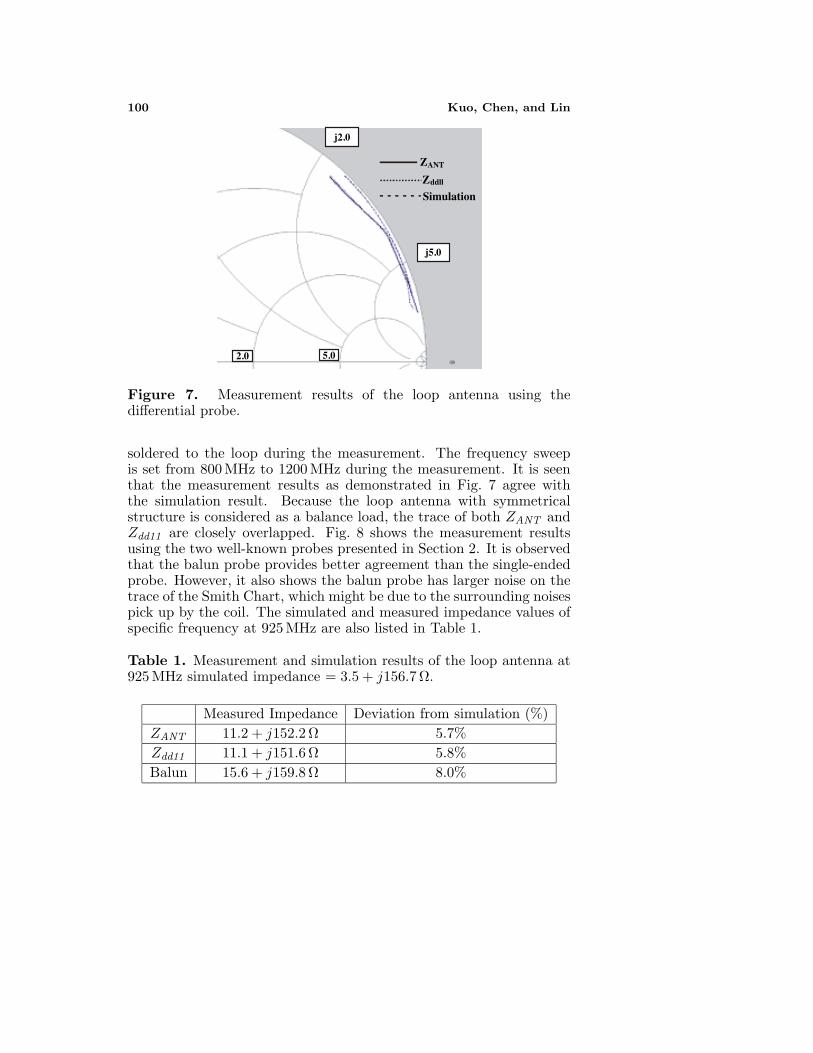
Figure 7. Measurement results of the loop antenna using thedifferential probe.
soldered to the loop during the measurement. The frequency sweepis set from 800 MHz to 1200 MHz during the measurement. It is seenthat the measurement results as demonstrated in Fig. 7 agree withthe simulation result. Because the loop antenna with symmetricalstructure is considered as a balance load, the trace of both ZANT andZdd11 are closely overlapped. Fig. 8 shows the measurement resultsusing the two well-known probes presented in Section 2. It is observedthat the balun probe provides better agreement than the single-endedprobe. However, it also shows the balun probe has larger noise on thetrace of the Smith Chart, which might be due to the surrounding noisespick up by the coil. The simulated and measured impedance values ofspecific frequency at 925 MHz are also listed in Table 1.
Table 1. Measurement and simulation results of the loop antenna at925 MHz simulated impedance = 3.5 + j156.7 Ω.
Progress In Electromagnetics Research, PIER 83, 2008 101
2.0 5.0
j5.0
j2.0 single-endedprobe
balunSimulation
Figure 8. Measurement results of the loop antenna using conventionalmethod.
Figure 9. Measurement of a patch antenna.
4.2. Measurement of Patch Antenna
Patch antenna is employed for various applications because of its lowprofile [20, 21], miniature size and wide bandwidth features [22–25].Most patch antennas are categorized as unbalanced antenna because ofits unsymmetrical structure [26, 27]. A patch antenna for the purposeof RFID tag on metal application is designed. Fig. 9 shows the patchantenna probed by the differential probe. The developed patch antennahas a dimension 100 × 40 × 1.6 mm3, with a rectangular patch andfeed position on the front surface of the FR4 substrate. A calibrationprocess based on fitting resonance frequency of a 50 Ohm patch antenna
102 Kuo, Chen, and Lin
2.0 5.0
j5.0
j2.0
ZANT
ddllZ
Simulation
Figure 10. Measurement results of the patch antenna using thedifferential probe.
was employed to calibrate the dielectric constant and loss tangent [9],which are found to be 4.28 and 0.018, respectively. The patch metal taghas a read range around 1.4 m when placed on metal plate and 2.0 m inthe air. The design and simulation was performed using Ansoft HFSSto achieve impedance 7.2 + j127.7 at 925 MHz, close to the conjugateimpedance value 11 − j131 of Alien UHF chip. Measurement resultsof ZANT and Zdd11 , along with simulation result are demonstrated inFig. 10. It is observed that ZANT is closer to the simulated impedanceover the entire frequency sweeping range. The difference betweenZANT and Zdd11 is mainly due the unbalanced nature of the patchantenna, which can be verified in Fig. 11 in which Za and Zb aredifferent from each other over the entire sweep frequencies.
Table 2. Measurement and simulation results of the patch antenna at925 MHz simulated impedance = 7.2 + j127.7 Ω.
For the single-ended probe, the measurement is setup in two waysso that the feed extended from the patch can be connected either to the
Progress In Electromagnetics Research, PIER 83, 2008 103
requency (MHz)F
Figure 11. Evaluation of unbalance of the patch antenna.
2.0 5.0
j5.0
j2.0 Patch to center pin
Patch to case
Simulation
Figure 12. Measurement of the patch antenna using the single-endedprobe.
center pin or to the case. The measured results illustrated in Fig. 12showing unacceptable measurement errors. On the other hand, Fig. 13shows the trace given by the balun probe has better agreement withsimulation. However, the noise induced by the coil is clearly identified.Table 2 compares deviation of measurement results from simulation.
104 Kuo, Chen, and Lin
2.0 5.0
j5.0
j2.0Balun
Simulation
Figure 13. Measurement of the patch antenna using the balun probe.
5. CONCLUSIONS
An accurate and reliable impedance measurement result highly relieson the configuration of the probe. Since the differential probehas a balanced structure, the imposed measurement error would beminimized. Experiment results clearly prove that the performance ofthe impedance measurement method based on differential probe hasbetter accuracy and noise immunity than the single ended probe andthe balun probe.
REFERENCES
1. Fan, Z. G., S. Qiao, J. T. Huangfu, and L. X. Ran, “Aminiaturized printed dipoles for 2.45 GHz RFID readers,” ProgressIn Electromagnetics Research, PIER 71, 149–158, 2007.
2. Kim, D.-Y. and J.-G. Yook, “Interference analysis of UHF RFIDsystems,” Progress In Electromagnetics Research B, Vol. 4, 115–126, 2008.
3. Shi, X.-L., X.-W. Shi, Q.-L. Huang, and F. Wei, “An enhancedbinary anti-collision algorithm of backtracking in RFID system,”Progress In Electromagnetics Research B, Vol. 4, 263–271, 2008.
4. Ng, M. L., K. S. Leong, and P. H. Cole, “Design and
Progress In Electromagnetics Research, PIER 83, 2008 105
miniaturization of an RFID tag using a simple rectangular patchantenna for metallic object identification,” IEEE Antennas andPropagation Society International Symposium, 1741–1744, Hawaii,USA, 2007.
5. Park, Y., S. Lee, J. Kang, and Y. C. Chung, “Various UHF RFIDtag for metallic object,” IEEE Antennas and Propagation SocietyInternational Symposium, 2285–2288, Hawaii, USA, 2007.
6. Ukkonen, L., M. Schaffrath, D. W. Engels, L. Sydanheimo, andM. Kivikoski, “Operability of folded microstrip patch-type tagantenna in the UHF RFID bands within 865–928 MHz,” IEEEAntennas and Wireless Propagation Letters, Vol. 5, No. 1, 414–417, Dec. 2006.
7. Choi, W., H. W. Son, J.-H. Bae, G. Y. Choi, C. S. Pyo, and J.-S. Chae, “An RFID tag using a planar inverted-F antenna capableof being stuck to metallic objects,” ETRI Journal, Vol. 28, No. 2,Apr. 2006.
8. Hirvonen, M., P. Pursula, K. Jaakkola, and K. Laukkanen,“Planar inverted-F antenna for radio frequency identification,”Electronic Letters, Vol. 40, No. 14, Jul. 2004.
9. Ng, M. L., K. S. Leong, and P. H. Cole, “A small passiveUHF RFID tag for metallic item identification,” InternationalTechnical Conference on Circuits/Systems, Computers andCommunications, 10–13, Chiang Mai, Thailand, Jul. 2006.
10. Loo, C.-H., K. Elmahgoub, F. Yang, A. Elsherbeni, D. Kajfez,A. Kishk, T. Elsherbeni, L. Ukkonen, L. Sydnheimo, M. Kivikoski,S. Merilampi, and P. Ruuskanen, “Chip impedance matching forUHF RFID tag antenna design,” Progress In ElectromagneticsResearch, PIER 81, 359–370, 2008.
11. Stutzman, W. L. and G. A. Thiele, Antenna Theory and Design,John Wiley & Sons, 1998.
12. Leong, K. S., M. N. Mg, and P. H. Cole, “Investigation of RFcable effect on RFID tag antenna impedance measurement,” IEEEAntennas and Propagation Society International Symposium, 573–576, Hawaii, USA, 2007.
13. Eunni, M. B., “A novel planar microstrip antenna design for UHFRFID,” M.S. Thesis, University of Kansas, Jul. 2006.
14. Camp, M., R. Herschman, T. Zelder, and H. Eul, “Determinationof the input impedance of RFID transponder antennas withnovel measurement procedure using a modified on-wafer-prober,”Advances in Radio Science, Vol. 5, 115–118, 2007.
15. Yang, Z. Q., T. Yang, and Y. Liu, “Aanalysis and design of a
16. Dobkin, D. M. and S. M. Weigand, “Environmental effects onRFID tag antennas,” Microwave Symposium Digest, 2005 IEEEMTT-S International, Jun. 12–17, 2005.
17. Palmer, K. D. and M. W. Rooyen, “Simple broadbandmeasurements of balanced loads using a network analyzer,” IEEETransactions on Instrumentation and Measurement, Vol. 55,No. 1, 266–272, Feb. 2006.
18. Fan, W., A. Lu, L. L. Wai, and B. K. Lok, “Mixed-mode S-parameter characterization of differential structures,” ElectronicsPackaging Technology, 5th Conference, 533–537, Dec. 10–12, 2003.
19. “Single-ended and differential S-parameters,” MAXIM applica-tion note, hfan-5.1.0.
20. Elsadek, H. and D. Nashaat, “Ultra mimiturized E-shaped dualband PIFA on cheap foam and FR4 substrate,” Journal ofElectromagnetic Waves and Applications, Vol. 20, No. 3, 291–300,2006.
21. Zhang, M. T., Y. B. Chen, Y. C. Jiao, and F. S. Zhang,“Dual circularly polarized antenna of compact structure for RFIDapplication,” Journal of Electromagnetic Waves and Applications,Vol. 20, No. 14, 1895–1902, 2006.
22. Sim, C. Y. D., “A novel dual frequency PIFA design forease of manufacturing,” Journal of Electromagnetic Waves andApplications, Vol. 21, No. 3, 409–419, 2007.
23. Elsadek, H. and D. Nashaat, “Quad band compact sizetrapezoidal PIFA antanna,” Journal of Electromagnetic Wavesand Applications, Vol. 21, No. 7, 865–876, 2007.
24. Khodaei, G. F., J. Nourinia, and C. Ghobadi, “A practicalminiaturized U-slot patch antenna with enhanced bandwidth,”Progress In Electromagnetics Research B, Vol. 3, 47–62, 2008.
25. Abbaspour, M. and H. R. Hassani, “Wideband star-shapedmicrostrip patch antenna,” Progress In Electromagnetics ResearchLetters, Vol. 1, 61–68, 2008.
26. Jolani, F. and A. M. Dadgarpour, “Compact M-slot foldedpatch antenna for WLAN,” Progress In Electromagnetics ResearchLetters, Vol. 3, 35–42, 2008.
27. Mahmoud, S. F. and A. F. Sheta, “Cavity mode analysis for arectangular patch with a shorting pin,” Journal of ElectromagneticWaves and Applications, Vol. 20, No. 14, 2013–2025, 2006.