An Advanced Imaging Method Based on Phased Array in NDT Xiaoyu (Joanna) Qiao 1 , Matthias Jobst 2 1 GE Inspection Technologies; 50 Industrial Park Rd, Lewistown, PA 17044-9312 US; [email protected]2 GE Inspection Technologies; Robert-Bosch-Str 3 Huerth, 50354 Germany; [email protected]Abstract Nowadays, the conventional Delay-And-Sum (DAS) imaging techniques has been implemented widely on commercial Linear Phased Array (LPA) products in NDT industry. It produces the satisfied image quality but at the cost of significant number of front-end channels. In this paper a novel beamforming imaging method was proposed aiming to provide customers the optimal and cost effective UT imaging instrument, which is capable of producing the satisfied imaging quality in terms of high contrast, high clarify and good resolution but with a small-scale array and less number of front-end channel. An adaptive coherent weighting strategy was proposed along with a synthesis fixed focus transmitting and dynamic receive focusing scheme. The performance of the new techniques was evaluated through simulation and the real experimental data. The results showed that the proposed new method can significantly reduce the front-end hardware complexity while produced satisfactory quality imaging. It can also effectively suppress unwanted interference from undesired directions which are inherently introduced by high-level side-lobe in the beam profile pattern of small-size arrays. 1. Introduction The techniques of Ultrasound Testing (UT) in NDT got great benefits from the solid development of conventional imaging for medical applications, where the Linear Phased Array (LPA) was introduced based on the simple Delay-And-Sum (DAS) beam-forming techniques. Up to now, conventional phased array still provides the best possible imaging quality despite the considerable larger aperture as the necessary. Nowadays, Ultrasound Testing based on PLA imaging has been widely used in NDT industry. As well known, beam-forming imaging performance strongly depends on the geometric structure of an adopted LPA transducer array. In order to avoid the grating lobes and achieve satisfied imaging quality, the elements in the linear array were arranged in half- wavelength distance. There is no doubt, for a larger transducer aperture, a very demanding parallel element channel number is required. These requirements results in a very complex front-end hardware, leading to high power consumption and production cost. A high performance portable UT instrument based on PLA, which uses a small-sized transducer aperture yet produces a reasonable satisfying imaging quality, is very attractive and desirable. Many efforts have been made by researchers and engineers [1,2] on developing a high-performance, small-scale, portable instrument based on LPA. Recently,
Transcript
An Advanced Imaging Method Based on Phased Array in NDT
Xiaoyu (Joanna) Qiao 1, Matthias Jobst 2
1 GE Inspection Technologies; 50 Industrial Park Rd,
Abstract Nowadays, the conventional Delay-And-Sum (DAS) imaging techniques has been implemented widely on commercial Linear Phased Array (LPA) products in NDT industry. It produces the satisfied image quality but at the cost of significant number of front-end channels. In this paper a novel beamforming imaging method was proposed aiming to provide customers the optimal and cost effective UT imaging instrument, which is capable of producing the satisfied imaging quality in terms of high contrast, high clarify and good resolution but with a small-scale array and less number of front-end channel. An adaptive coherent weighting strategy was proposed along with a synthesis fixed focus transmitting and dynamic receive focusing scheme. The performance of the new techniques was evaluated through simulation and the real experimental data. The results showed that the proposed new method can significantly reduce the front-end hardware complexity while produced satisfactory quality imaging. It can also effectively suppress unwanted interference from undesired directions which are inherently introduced by high-level side-lobe in the beam profile pattern of small-size arrays. 1. Introduction The techniques of Ultrasound Testing (UT) in NDT got great benefits from the solid development of conventional imaging for medical applications, where the Linear Phased Array (LPA) was introduced based on the simple Delay-And-Sum (DAS) beam-forming techniques. Up to now, conventional phased array still provides the best possible imaging quality despite the considerable larger aperture as the necessary. Nowadays, Ultrasound Testing based on PLA imaging has been widely used in NDT industry. As well known, beam-forming imaging performance strongly depends on the geometric structure of an adopted LPA transducer array. In order to avoid the grating lobes and achieve satisfied imaging quality, the elements in the linear array were arranged in half-wavelength distance. There is no doubt, for a larger transducer aperture, a very demanding parallel element channel number is required. These requirements results in a very complex front-end hardware, leading to high power consumption and production cost. A high performance portable UT instrument based on PLA, which uses a small-sized transducer aperture yet produces a reasonable satisfying imaging quality, is very attractive and desirable. Many efforts have been made by researchers and engineers [1,2] on developing a high-performance, small-scale, portable instrument based on LPA. Recently,
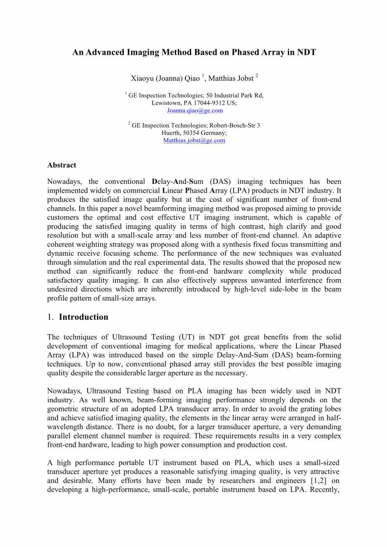
GE Inspection Technologies has successfully implemented an advanced beamforming technique: Synthetic Transmit Focusing and Dynamic Receive Focusing (STF-DRF) product. A small-size array composed of 16 elements was adopted. These new beamforming techniques showed excellent capabilities to produce a very good compromise between front-end hardware complexity and inspection imaging quality. Due to the small scale array with fewer elements contained, the point spread function of the transducer aperture still inherently presents the drawback property of high side lobes. The unwanted interferences from undesired directions are unfortunately introduced, which shows up as high-level background noise. Therefore, the imaging quality is unavoidably degraded. In order to overcome this inherent limitation to produce a high quality image, an innovative ultrasound imaging method based on PLA was proposed and explained in this paper. It combines the techniques of STF-DRF beam-steering sector-scan imaging with the strategy of adaptive coherent measurement weighting. The newly proposed method gives the portable UT instrument desirable features; such as a small-size transducer aperture, acceptable sensitivity-detecting capability and high contrast imaging quality. The simulation and experimental data test was conducted and yielded successful results, producing high quality images via the proposed methods. This proved that the new method is a viable solution to produce clear images yet reducing the front-end hardware complexity. 2. Beam-forming Imaging Method for Ultrasound Testing Based on an aperture, the goal of the beam-forming process is to construct a spatial filter which is capable to optimally extract the reflected signals from the desired direction and suppressing unwanted signals reflected from all non-interesting directions efficiently. The key factor to the spatial resolution of imaging inspection, is mainly determined by the beam-patterns production between the transmission array and the receive array. 2.1 Conventional beamforming focusing imaging. The premier beam-forming method for UT imaging in the near field is Confocal-Transmit-Receive Imaging, which is a technique commonly used by existing products in the market. Improvement was made by implementing multiple receive-focusing zones instead of single fixed-receive focus zone in the beamforming method. Further improvement includes implementing Multiple-Transmit-Fixed-Focusing-Zones and Dynamic-Receive-Fixed Imaging. This is recognized as a better solution since it is close to fully-dynamic transmit-and-receive focusing. However, increasing the number of multiple-transmit zones caused the number of the firing events to increase. Therefore the frame rate was reduced. The beamforming methods described above are based on the DAS principle. As an example, the beam-steering sector scan was shown in Figure 1. If a defect exists at a scanned individual pixel position (x,z), the defect reflection signal were received by all element channels in the receive aperture from α angle direction, where α is beam steering angle. By means of time-delay compensation for the time of flight of acoustic wave round-trip, the beamforming are processed by summing all the time-delay compensated received signals together.
Figure 1 -‐ Beam Steering Beamforming Imaging Based on Phased Array
The extracted signal is then converted into the pixel intensity at the corresponding positions in the scanned image.
∑∑= =
−−=N
i
N
jjviTransjizx zxzxtSP
1 1)(Re)(,, )),(),(( ττ
(1)
Where ),()( zxiTransτ and ),()(Re zxjvτ are the transmitting delay and receiving delay. The first and second summations are for transmitting and receiving beamforming respectively, which corresponds to time delay compensation for firing and echo paths. The calculation of time delay depends on the defined beamforming method, such as fixed focusing, multi-zone fixed focusing or fully dynamic focusing. 2.2 A new advanced beamforming focusing imaging method. In our new advanced beamforming focusing imaging method, sub-arrays were selected from the whole aperture and defined as the transmitting sub-arrays. Each individual sub-array was composed by M elements, which were active in its sub-array firing event. All elements in the whole aperture were active during echo signal collection. The fixed transmitting focusing and dynamic receiving focusing beamforming was employed for this imaging processing. Meanwhile, the Coherent Factor is proposed and functions as adaptive coherent confidence ratio, which was introduced into focusing beamforming process by weighting the synthetic beamforming output value. It plays a role as evaluating the alignment quality of all time-delay compensated signals. Through applying the adaptive coherent measurement weighting, the in-phase signals were strongly emphasized by the high adaptive coherent confidence ratio, while the out-of-phase signals were significantly suppressed by a low ratio. The scanned pixel Adaptive STF-DRF beamforming imaging pixel can be calculated:
∑ ∑=
−=L
k
N
jjvkSubjvkSubkSubzx zxtStzxCFP
1)(Re)()(Re),()(, )),((),,( τ
(2)
α
∑
∑
=
=
−
−= N
jjvkSubjvkSub
N
jjvkSubjvkSub
kSub
zxtSN
zxtStzxCF
1
2
)(Re)()(Re),(
2
1)(Re)()(Re),(
)(
)),((
)),((),,(
τ
τ (3)
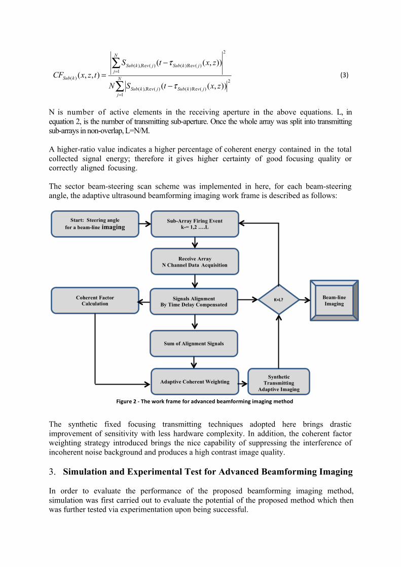
N is number of active elements in the receiving aperture in the above equations. L, in equation 2, is the number of transmitting sub-aperture. Once the whole array was split into transmitting sub-arrays in non-overlap, L=N/M. A higher-ratio value indicates a higher percentage of coherent energy contained in the total collected signal energy; therefore it gives higher certainty of good focusing quality or correctly aligned focusing. The sector beam-steering scan scheme was implemented in here, for each beam-steering angle, the adaptive ultrasound beamforming imaging work frame is described as follows:
Figure-2 The work frame for advanced beamforming imaging method The synthetic fixed focusing transmitting techniques adopted here brings drastic improvement of sensitivity with less hardware complexity. In addition, the coherent factor weighting strategy introduced brings the nice capability of suppressing the interference of incoherent noise background and produces a high contrast image quality. 3. Simulation and Experimental Test for Advanced Beamforming Imaging In order to evaluate the performance of the proposed beamforming imaging method, simulation was first carried out to evaluate the potential of the proposed method which then was further tested via experimentation upon being successful.
Sub-Array Firing Event k-= 1,2 ….L
Receive Array N Channel Data Acquisition
Signals Alignment By Time Delay Compensated
Sum of Alignment Signals
Adaptive Coherent Weighting
Coherent Factor Calculation
Start: Steering angle for a beam-line imaging
Synthetic Transmitting
Adaptive Imaging
K=L? Beam-line Imaging
Figure 2 -‐ The work frame for advanced beamforming imaging method
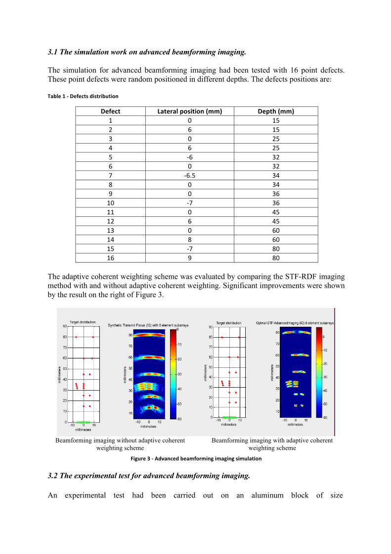
3.1 The simulation work on advanced beamforming imaging. The simulation for advanced beamforming imaging had been tested with 16 point defects. These point defects were random positioned in different depths. The defects positions are: Table 1 -‐ Defects distribution
The adaptive coherent weighting scheme was evaluated by comparing the STF-RDF imaging method with and without adaptive coherent weighting. Significant improvements were shown by the result on the right of Figure 3.
Beamforming imaging without adaptive coherent
weighting scheme Beamforming imaging with adaptive coherent
weighting scheme
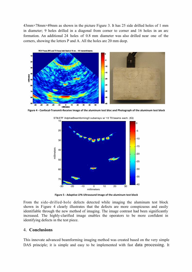
Figure 3 -‐ Advanced beamforming imaging simulation 3.2 The experimental test for advanced beamforming imaging. An experimental test had been carried out on an aluminum block of size
43mm×78mm×49mm as shown in the picture Figure 3. It has 25 side drilled holes of 1 mm in diameter; 9 holes drilled in a diagonal from corner to corner and 16 holes in an arc formation. An additional 24 holes of 0.8 mm diameter was also drilled near one of the corners, showing the letters P and A. All the holes are 20 mm deep.
Figure 4 -‐ Confocal-‐Transmit-‐Receive Image of the aluminum test bloc and Photograph of the aluminum test block
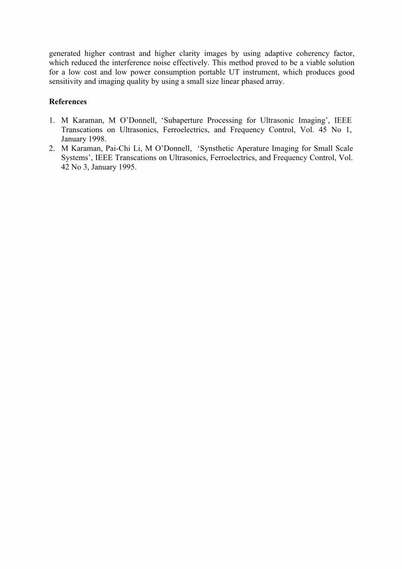
Figure 5 -‐ Adaptive LPA Ultrasound Image of the aluminum test block
From the side-drilled-hole defects detected while imaging the aluminum test block shown in Figure 4 clearly illustrates that the defects are more conspicuous and easily identifiable through the new method of imaging. The image contrast had been significantly increased. The highly-clarified image enables the operators to be more confident in identifying defects in the test piece. 4. Conclusions This innovate advanced beamforming imaging method was created based on the very simple DAS principle; it is simple and easy to be implemented with fast data processing. It
generated higher contrast and higher clarity images by using adaptive coherency factor, which reduced the interference noise effectively. This method proved to be a viable solution for a low cost and low power consumption portable UT instrument, which produces good sensitivity and imaging quality by using a small size linear phased array. References 1. M Karaman, M O’Donnell, ‘Subaperture Processing for Ultrasonic Imaging’, IEEE
Transcations on Ultrasonics, Ferroelectrics, and Frequency Control, Vol. 45 No 1, January 1998.
2. M Karaman, Pai-Chi Li, M O’Donnell, ‘Synsthetic Aperature Imaging for Small Scale Systems’, IEEE Transcations on Ultrasonics, Ferroelectrics, and Frequency Control, Vol. 42 No 3, January 1995.