AUTHORS Gary G. Lash Department of Geosciences, State University of New York – College at Fredonia, Fredonia, New York 14063; [email protected]Gary received his B.S. degree from Kutztown State University and his M.S. degree and his Ph.D. from Lehigh University. Before working in the fractured Upper Devonian shales of the western New York state region of the Appalachian basin, he was involved in strati- graphic and structural investigations of thrusted Cambrian–Ordovician deposits of the central Appalachians. Terry Engelder Department of Geo- sciences, Pennsylvania State University, Uni- versity Park, Pennsylvania 16802; [email protected]Terry received his B.S. degree from Pennsyl- vania State University, where he joined the faculty after tours at Texas A&M University (Ph.D.) and the Lamont-Doherty Geological Observatory (postdoctoral study). After col- laborating with him on brittle fracture and earth stress, his former students have moved on to companies including Anadarko, Atlas Western, British Petroleum, Chevron, Exxon- Mobil, Marathon, Royal Dutch Shell, Schlum- berger, Shell U.S.A., and Texaco. ACKNOWLEDGEMENTS This article benefited from the reviews of Stephen Cumella and Stephen Laubach. We thank Peter Bush and his staff at the Univer- sity of Buffalo, South Campus Instrumenta- tion Center, School of Dental Medicine, for help with the electron microscopy. Support also came from Penn State’s Seal Evaluation Consortium. An analysis of horizontal microcracking during catagenesis: Example from the Catskill delta complex Gary G. Lash and Terry Engelder ABSTRACT Horizontal bitumen-filled microcracks are common within clay lami- nae of the finely laminated organic carbon-rich shale in the lower half of the heavily jointed Upper Devonian Dunkirk Shale, western New York state. Such cracks are not found higher in the Dunkirk Shale, where moderate bioturbation resulted in a relatively porous and permeable microfabric. Horizontal microcracks in a hydrocar- bon source rock that carries regional vertical joints indicating a horizontal least principal stress owe their presence to material properties of the fractured shale and the magnitude and orien- tation of the crack-driving stress during kerogen maturation. Three material properties favored the horizontal initiation of microcracks in the Dunkirk Shale: (1) the abundance of flat kerogen grains ori- ented parallel to layering; (2) a marked strength anisotropy in large part caused by the laminated nature of the rock; and (3) the tight, strongly oriented planar clay-grain fabric produced by gravita- tional compaction of flocculated clay at shallow-burial depth. The latter was especially important to sustaining elevated pore pres- sure, the crack-driving stress, which was generated by the con- version of kerogen to bitumen. Poroelastic deformation of the low-permeability laminated shale pressurized by catagenesis, per- haps enhanced by compaction disequilibrium prior to kerogen conversion, elevated the in-situ horizontal stress in excess of the vertical stress, which remained constant during pore-pressure buildup, thereby favoring the propagation of microcracks in the horizontal plane. GEOLOGIC NOTE AAPG Bulletin, v. 89, no. 11 (November 2005), pp. 1433 – 1449 1433 Copyright #2005. The American Association of Petroleum Geologists. All rights reserved. Manuscript received December 20, 2004; provisional acceptance April 4, 2005; revised manuscript received May 23, 2005; final acceptance May 25, 2005. DOI:10.1306/05250504141
Transcript
AUTHORS
Gary G. Lash � Department of Geosciences,State University of New York–College atFredonia, Fredonia, New York 14063;[email protected]
Gary received his B.S. degree from KutztownState University and his M.S. degree and hisPh.D. from Lehigh University. Before workingin the fractured Upper Devonian shales ofthe western New York state region of theAppalachian basin, he was involved in strati-graphic and structural investigations of thrustedCambrian–Ordovician deposits of the centralAppalachians.
Terry Engelder � Department of Geo-sciences, Pennsylvania State University, Uni-versity Park, Pennsylvania 16802;[email protected]
Terry received his B.S. degree from Pennsyl-vania State University, where he joined thefaculty after tours at Texas A&M University(Ph.D.) and the Lamont-Doherty GeologicalObservatory (postdoctoral study). After col-laborating with him on brittle fracture andearth stress, his former students have movedon to companies including Anadarko, AtlasWestern, British Petroleum, Chevron, Exxon-Mobil, Marathon, Royal Dutch Shell, Schlum-berger, Shell U.S.A., and Texaco.
ACKNOWLEDGEMENTS
This article benefited from the reviews ofStephen Cumella and Stephen Laubach. Wethank Peter Bush and his staff at the Univer-sity of Buffalo, South Campus Instrumenta-tion Center, School of Dental Medicine, forhelp with the electron microscopy. Supportalso came from Penn State’s Seal EvaluationConsortium.
An analysis of horizontalmicrocracking duringcatagenesis: Example fromthe Catskill delta complexGary G. Lash and Terry Engelder
ABSTRACT
Horizontal bitumen-filled microcracks are common within clay lami-
nae of the finely laminated organic carbon-rich shale in the lower
half of the heavily jointed Upper Devonian Dunkirk Shale, western
New York state. Such cracks are not found higher in the Dunkirk
Shale, where moderate bioturbation resulted in a relatively porous
and permeable microfabric. Horizontal microcracks in a hydrocar-
bon source rock that carries regional vertical joints indicating a
horizontal least principal stress owe their presence to material
properties of the fractured shale and the magnitude and orien-
tation of the crack-driving stress during kerogen maturation. Three
material properties favored the horizontal initiation of microcracks
in the Dunkirk Shale: (1) the abundance of flat kerogen grains ori-
ented parallel to layering; (2) a marked strength anisotropy in large
part caused by the laminated nature of the rock; and (3) the tight,
strongly oriented planar clay-grain fabric produced by gravita-
tional compaction of flocculated clay at shallow-burial depth. The
latter was especially important to sustaining elevated pore pres-
sure, the crack-driving stress, which was generated by the con-
version of kerogen to bitumen. Poroelastic deformation of the
low-permeability laminated shale pressurized by catagenesis, per-
haps enhanced by compaction disequilibrium prior to kerogen
conversion, elevated the in-situ horizontal stress in excess of the
vertical stress, which remained constant during pore-pressure
buildup, thereby favoring the propagation of microcracks in the
horizontal plane.
GEOLOGIC NOTE
AAPG Bulletin, v. 89, no. 11 (November 2005), pp. 1433– 1449 1433
Copyright #2005. The American Association of Petroleum Geologists. All rights reserved.
Manuscript received December 20, 2004; provisional acceptance April 4, 2005; revised manuscriptreceived May 23, 2005; final acceptance May 25, 2005.
DOI:10.1306/05250504141
INTRODUCTION
Horizontal microcracks in fine-grained, low-permeability
source rocks serve as primary hydrocarbon-migration
pathways that, when interconnected, facilitate expul-
sion into nearby reservoir rocks (Snarsky, 1962; Mom-
per, 1978; du Rouchet, 1981; Talukdar et al., 1987;
Ozkaya, 1988; Lehner, 1991; Capuano, 1993; Mar-
quez and Mountjoy, 1996). Several investigators main-
tain that the horizontal propagation of maturation-
related microcracks in laminated source rocks is a
consequence of a compaction-induced strength anisot-
ropy and/or a concentration of flattened kerogen grains
in parallel layers (e.g., Meissner, 1978; Talukdar et al.,
1987; Ozkaya, 1988; Lehner, 1991; Vernik, 1994). This
fracture orientation requires that the cracks opened
against the total vertical stress, S v, which typically,
in epeirogenic and continental-margin settings, is
the maximum principal stress (e.g., Gaarenstroom
et al., 1993; Grauls and Baleix, 1994; Finkbeiner and
Zoback, 1998). Because total stress is such a strong
governor of crack propagation, it is of interest to
investigate conditions under which local or in-situ
stresses during hydrocarbon maturation may differ
from the most commonly reported basinal stress con-
figuration in which Sv > Sh, the total least horizontal
stress. Indeed, the few instances where S v is docu-
mented to be the least principal stress have been
described from overpressured sedimentary basins (e.g.,
Ervine and Bell, 1987). It is important to consider
whether such in-situ stresses (i.e., S v < Sh) in over-
pressured source rocks, acting in tandem with mate-
rial properties, including layer-perpendicular strength
anisotropy and kerogen grain shape, can lead to
horizontal crack initiation and propagation during
catagenesis.
This article documents the growth of horizontal
microcracks in the Upper Devonian Dunkirk black
shale, one of several Devonian source rocks charg-
ing the hydrocarbon system of the Appalachian ba-
sin. Our calculations suggest that strength anisotropy,
kerogen grain shape, and clay-grain microfabric were
instrumental in initiating the horizontal microcracks.
Petrographic and SEM observations tie the driving
mechanism for microcrack propagation in the organic-
rich shale to a buildup of internal pressure that ac-
companied transformation of kerogen to bitumen. We
propose that the pervasive increase in internal pres-
sure caused by catagenesis could have induced a poro-
elastic response within the Dunkirk source rock during
the conversion of kerogen. In its extreme, poroelastic
deformation is capable of causing an increase in Sh
to the point that Sh > Sv, thereby favoring the post-
initiation growth of microcracks in the horizontal
plane.
DUNKIRK SHALE
The Dunkirk Shale, approximately 17 m (55 ft) of
black and grayish-black shale and sparse, thin silt-
stone beds, is the youngest of the Upper Devonian
black shale units of the Catskill delta complex, west-
ern New York Appalachian plateau (Figure 1). The
shale carries several sets of vertical joints that demon-
strate the extent to which the formation was sub-
ject to a regional stress state where S h < S v (Lash
et al., 2004). The presence of these regional joint
sets is compelling evidence that horizontal micro-
crack propagation manifests unusual local or in-situ
conditions.
The total organic carbon (TOC) content of the
Dunkirk Shale diminishes upsection from a maximum
of 4.63 wt.% in exposures along the Lake Erie shore-
line near Dunkirk, New York (Figure 1) (Lash et al.,
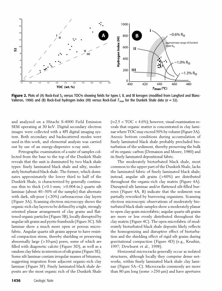
2004). Comparison of (1) the S2 parameter (second
peak in Rock-Eval pyrolysis) with TOC (Figure 2A)
and (2) the hydrogen index (HI; mg hydrocarbons/g
TOC) with Rock-Eval Tmax (temperature of maxi-
mum release of hydrocarbons of a sample during py-
rolysis) (Figure 2B) suggests that organic matter in the
Dunkirk Shale is dominantly oil-prone type II kerogen
of marine origin. Measured vitrinite reflectance (Ro)
values of Dunkirk Shale samples range from 0.55 to
0.73% (average = 0.62%; n = 6; Lash et al., 2004),
thereby placing this unit close to or within the oil-
generating window (Tissot and Welte, 1984; Espita-
lie, 1986).
The fact that different types of organic matter
generate petroleum at different levels of thermal ma-
turity (e.g., Lewan et al., 2002) precludes simple judg-
ments regarding the extent of petroleum generation in
a source rock based solely on vitrinite reflectance. We
assessed the degree of petroleum generation in the
Dunkirk Shale by the calculation of the transformation
ratio, TR, using HI values according to the following
expression:
TR ¼ HIo � HIm
HImð1Þ
1434 Geologic Note
in which HIo and HIm are hydrogen index values for
thermally immature and mature source rocks, respec-
tively. The transformation ratio expressed in this way
ranges from 0 for thermally immature rocks to 1.0 for
complete transformation of kerogen to hydrocarbons.
For HIo, we used the HI value (399 mg hydrocarbons/g
TOC) of that sample defined by an Ro of 0.55%. A shale
sample collected about 1.5 m (4.9 ft) above the afore-
mentioned sample has an HI of 416 mg hydrocarbons/g
TOC, a value that might be closer to the prematuration
HI. The HI of the most thermally mature Dunkirk
Shale sample (Ro = 0.73%), 355 mg hydrocarbons/g
TOC, was used for HIm. The calculated TR of the
Dunkirk Shale then falls in the range of 0.11–0.13, a bit
above that value generally accepted to mark the onset
of petroleum generation (0.1; Jarvie and Lundell, 2001).
However, inasmuch as our HIo value was obtained
from a sample that may already have generated hy-
drocarbons (Ro = 0.55%), we view our calculated TR as
a minimum estimate.
SHALE MICROFABRIC ANDHORIZONTAL MICROCRACKS
Microscopic (thin-section and SEM) analysis of the
Dunkirk Shale was conducted to assess those micro-
fabric features, including microcracks, that could have
sustained primary migration through the organic-rich
shale. Samples were recovered from deeper than 5 cm
(2 in.) into exposures to avoid collection from the weath-
ered, fissile veneer that covers most outcrops. Standard
petrographic thin sections cut perpendicular to bedding
were prepared from each shale sample. The abundance
of silt (quartz and feldspar) was quantified by visual
estimate using standard comparison charts (Flugel,
1982). Samples were prepared for SEM following
the methods outlined by O’Brien and Slatt (1990).
Each shale sample was mounted on double-sided ad-
hesive carbon tape such that the viewing direction was
normal to bedding. Samples were coated with 20 nm
of evaporated carbon to render the surface conductive
Figure 1. Location map and generalized stratigraphic column of the Upper Devonian sequence of western New York.
Lash and Engelder 1435
and analyzed on a Hitachi S-4000 Field Emission
SEM operating at 30 keV. Digital secondary electron
images were collected with a 4PI digital imaging sys-
tem. Both secondary and backscattered modes were
used in this work, and elemental analysis was carried
out by use of an energy-dispersive x-ray unit.
Petrographic examination of a suite of samples col-
lected from the base to the top of the Dunkirk Shale
reveals that the unit is dominated by two black shale
types: finely laminated black shale and silty, moder-
ately bioturbated black shale. The former, which domi-
nates approximately the lower third to half of the
Dunkirk Shale, is characterized by generally continu-
ous thin to thick (>0.1-mm; >0.004-in.) quartz silt
laminae (about 40–50% of the sample) that alternate
with dark, silt-poor (<20%) carbonaceous clay layers
(Figure 3A). Scanning electron microscopy shows the
organic-rich clay layers to be defined by a tight, strongly
oriented planar arrangement of clay grains and flat-
tened organic particles (Figure 3B), locally disrupted by
angular silt grains and pyrite framboids (Figure 3C). Silt
laminae show a much more open or porous micro-
fabric. Angular quartz silt grains appear to have resist-
ed compaction stress, thereby shielding or preserving
abnormally large (>10-mm) pores, some of which are
filled with diagenetic calcite (Figure 3D), as well as a
random clay fabric in interstices of silt grains (Figure 3E).
Some silt laminae contain irregular masses of bitumen,
suggesting migration from adjacent organic-rich clay
laminae (Figure 3F). Finely laminated black shale de-
posits are the most organic rich of the Dunkirk Shale
(�2.5 < TOC < 4.6%); however, visual examination re-
veals that organic matter is concentrated in clay lami-
nae where TOC may exceed 50% by volume (Figure 3A).
Anoxic bottom conditions during accumulation of
finely laminated black shale probably precluded bio-
turbation of the sediment, thereby preserving the bulk
of its organic carbon (Demaison and Moore, 1980) and
its finely laminated depositional fabric.
The moderately bioturbated black shale, most
common to the upper part of the Dunkirk Shale, lacks
the laminated fabric of finely laminated black shale;
instead, angular silt grains (>60%) are distributed
throughout the organic-rich clay matrix (Figure 4A).
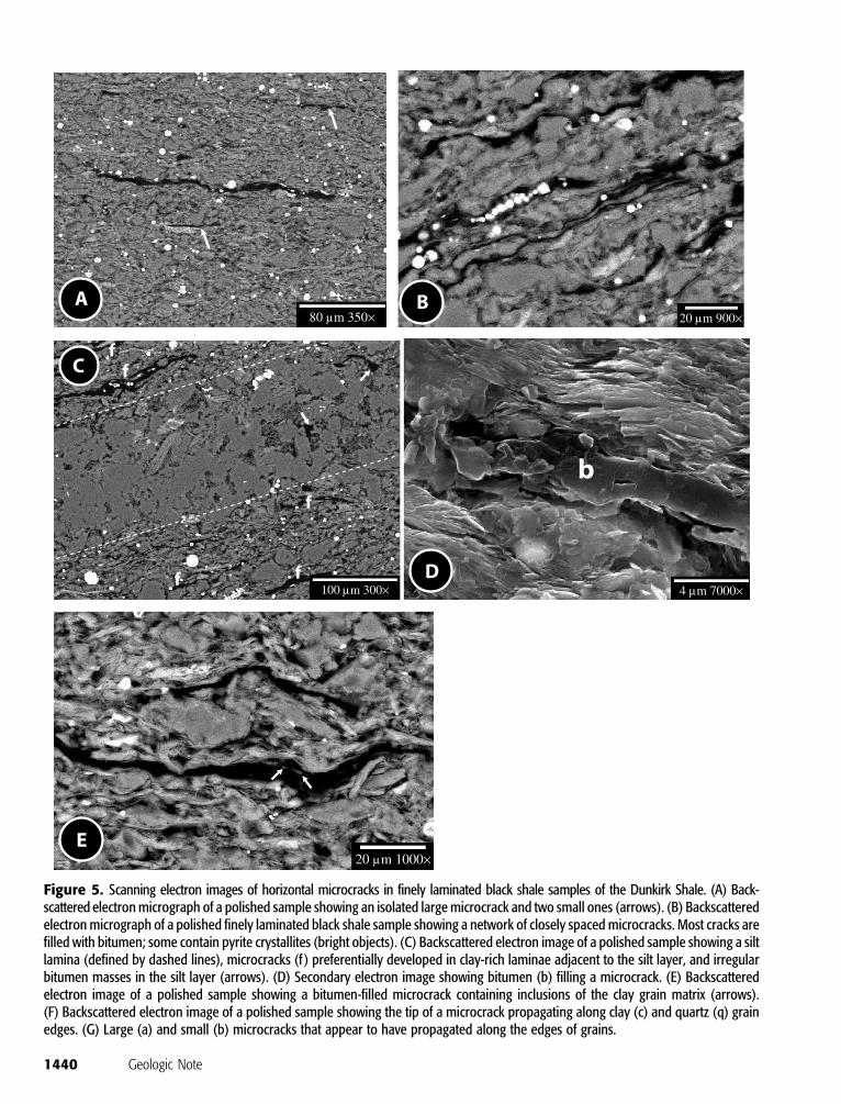
Horizontal microcracks generally occur as isolated
structures, although locally they comprise dense net-
works, within finely laminated black shale clay lami-
nae (Figure 5A–C). Microcracks commonly are more
than 80 mm long (some >250 mm) and have apertures
Figure 2. Plots of (A) Rock-Eval S2 versus TOC% showing fields for types I, II, and III kerogen (modified from Langford and Blanc-Valleron, 1990) and (B) Rock-Eval hydrogen index (HI) versus Rock-Eval Tmax for the Dunkirk Shale data (n = 32).
1436 Geologic Note
Figure 3. Optical and electron micro-graphs of finely laminated black shale sam-ples. (A) Interlaminated silt and organic-rich clay (scale = 0.5 mm [0.02 in.]).(B) Secondary electron micrograph ofthe planar microfabric of a clay laminasample. (C) Secondary electron micro-graph showing compacted clay grainswrapping a pyrite framboid in a clay lami-na sample. (D) Backscattered electronmicrograph of a polished silt layer sam-ple showing quartz silt grains (s), dia-genetic calcite-filling pore space (c), andporosity (arrows). (E) Secondary elec-tron micrograph in a polished silt layersample showing quartz silt grains (s) sur-rounded by a porous, rather random claymicrofabric. Note the void spaces in theclay grain matrix (arrows). (F) Backscat-tered electron micrograph of a silt layersample showing an irregular bitumenmass (b), quartz silt grains (s), and pyrite(bright grains).
Lash and Engelder 1437
Figure 4. Optical and electron micro-graphs of moderately bioturbated blackshale samples. (A) Diffuse silt lamina andabundant dispersed silt grains (scale =0.5 mm [0.02 in.]). (B) Bioturbated siltlaminae and/or flattened silt-filled burrowsand abundant dispersed silt grains (scale =0.5 mm [0.02 in.]). (C) Secondary electronmicrograph of a polished sample show-ing quartz silt grains (s) floating in a claygrain matrix. Note the anomalously largepore in the center of the image. (D) Sec-ondary electron image showing a large,angular quartz silt grain supported by amatrix of randomly oriented clay grains.The open clay microfabric in this sampleis more likely a consequence of bioturba-tion instead of the shielding effect of thissingle large quartz grain.
1438 Geologic Note
on the order of 3–10 mm (Figure 5A, B). Most cracks are
filled with bitumen (Figure 5B, D), as indicated by
higher-than-background levels of molybdenum, lead,
and sulfur (e.g., Lomando, 1992; Kattai, 1994); we ob-
served that fewer than 20% of the cracks are open or
contain nothing more than pyrite crystallites (Figure 5B).
Some microcracks contain inclusions of wall rock
(clay-grain fragments) within bitumen (Figure 5E). The
presence of bitumen as the only crack-filling material
indicates that microcracking occurred during, and as a
consequence of, the decomposition of kerogen to bi-
tumen (e.g., Comer and Hinch, 1987).
The microcracks are mode I cracks (opening
perpendicular to the crack surfaces with a shear stress
of zero) as indicated by the close match of grain
shapes across apertures (Figure 5E), the lack of evi-
dence for shear offset along cracks, and observations
of grains being wedged apart by propagating cracks
(Figure 5F, G). Microcracks are approximately par-
allel to layering and likely propagated along paths
controlled by the planar clay-grain microfabric of
the host sediment. Finally, microcracking was con-
centrated along the edges of grains (Figure 5G); rarely
did cracks propagate through grains other than clay-
grain books. These observations, then, are consistent
with previous conclusions that maturation-related
microcracks are commonly horizontal (e.g., Meissner,
1978; Talukdar et al., 1987; Littke et al., 1988; Capuano,
1993; Vernik, 1994; Pitman et al., 2001).
CONDITIONS LEADING TO HORIZONTALMICROCRACKING WITHIN THEDUNKIRK SHALE
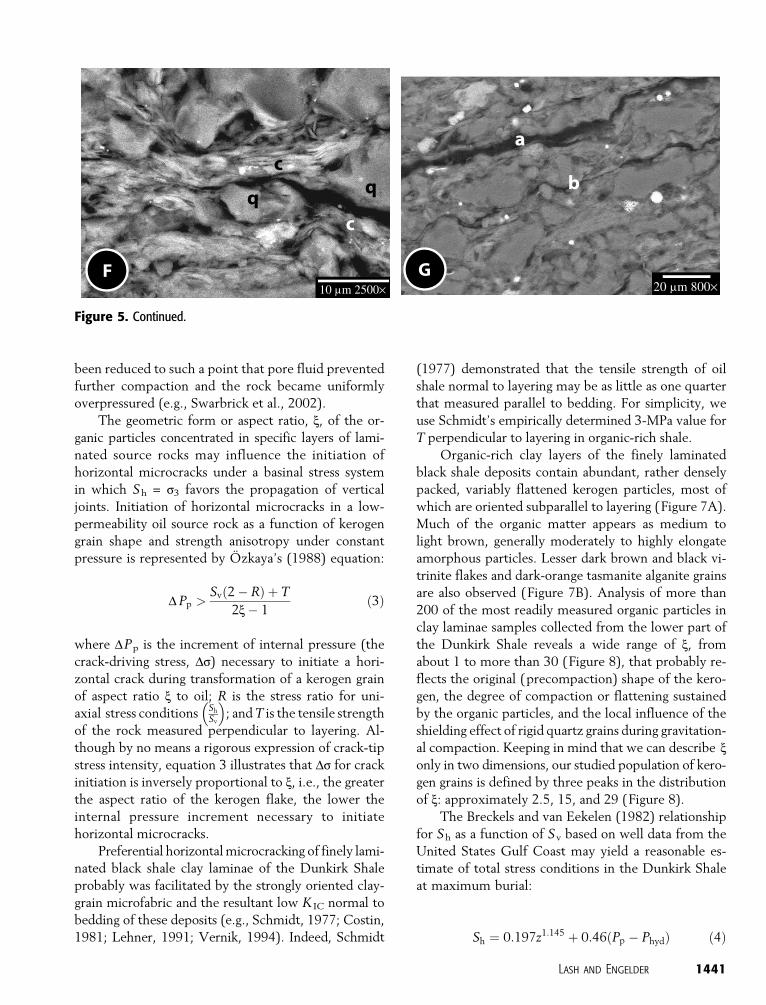
Horizontal microcracks formed preferentially in finely
laminated black shale clay laminae in the lower in-
terval of the Dunkirk Shale, where they propagated
from within flattened kerogen grains or from along
kerogen-mineral interfaces (Figure 6). The abundant,
relatively impermeable clay laminae most likely sus-
tained internal pressure at a level high enough to drive
microcracks during the conversion of kerogen to hy-
drocarbons. The relatively permeable microfabric of
moderately bioturbated black shale deposits higher in
the Dunkirk Shale, however, enabled these sediments
to more readily expel fluids released by catagenesis.
Indeed, previous considerations of microcracking in
source rocks suggest that horizontal microcracking
requires the buildup and maintenance of pore pressure,
Pp, under undrained conditions (e.g., Ozkaya, 1988a;
Lehner, 1991).
The general equation governing crack propagation
according to linear elastic fracture mechanics specifies
that the crack-tip stress intensity, K I, must equal or
exceed the strength of the rock according to
KI ¼ DsYffiffiffiffiffiffip c
p� KIc ð2Þ
where K Ic is the fracture toughness, c is the crack half-
length, Y is the shape factor, and Ds is the crack-
driving stress. The latter parameter reflects the super-
position of Pp on the least compressive total principal
stress (i.e., s3, which may be either Sv or Sh, de-
pending on local conditions) in a basin so that Ds =
Pp� Sv (= s3) for horizontal microcrack propagation.
Equilibrium crack propagation, then, is a balance among
the shape and length of the crack, the strength of the
rock, and the crack-driving stress. These parameters
can be grouped into two general classes depending on
whether they are a manifestation of some material
property (i.e., K Ic, Y, and c) or they arise from bound-
ary conditions (i.e., Ds). Crack-driving stress, which
was achieved through a maturation-related increase
in Pp, and material properties have different func-
tions in the development and growth of horizontal mi-
crocracks in the Dunkirk black shale and thus will be
treated separately.
The Role of Material Properties: Horizontal Initiationas a Consequence of Kerogen Grain Shape andStrength Anisotropy
Rock material properties, including layer-perpendicu-
lar strength anisotropy and the shape of initiation flaws
for microcrack propagation, evolve during consolida-
tion. Soon after deposition, flocculated organic-rich
clay laminae of unbioturbated, finely laminated black
shale deposits of the Dunkirk Shale underwent rapid
mechanical compaction into a tight, mechanically sta-
ble planar microfabric (e.g., Lash and Blood, 2004).
Interlaminated silt-rich layers, however, did not expe-
rience the same degree of compaction strain, a conse-
quence of the shielding effect of the rigid silt grains that
preserved a more random clay fabric and anomalously
large pores (e.g., Krushin, 1997; Katsube and Williamson,
1998; Dewhurst et al., 1998). Further burial carried
the Dunkirk Shale to the top of the oil window by the
end of the Carboniferous (Lash et al., 2004), by which
time the permeability of the laminated sequence had
Lash and Engelder 1439
Figure 5. Scanning electron images of horizontal microcracks in finely laminated black shale samples of the Dunkirk Shale. (A) Back-scattered electron micrograph of a polished sample showing an isolated large microcrack and two small ones (arrows). (B) Backscatteredelectron micrograph of a polished finely laminated black shale sample showing a network of closely spaced microcracks. Most cracks arefilled with bitumen; some contain pyrite crystallites (bright objects). (C) Backscattered electron image of a polished sample showing a siltlamina (defined by dashed lines), microcracks (f ) preferentially developed in clay-rich laminae adjacent to the silt layer, and irregularbitumen masses in the silt layer (arrows). (D) Secondary electron image showing bitumen (b) filling a microcrack. (E) Backscatteredelectron image of a polished sample showing a bitumen-filled microcrack containing inclusions of the clay grain matrix (arrows).(F) Backscattered electron image of a polished sample showing the tip of a microcrack propagating along clay (c) and quartz (q) grainedges. (G) Large (a) and small (b) microcracks that appear to have propagated along the edges of grains.
1440 Geologic Note
been reduced to such a point that pore fluid prevented
further compaction and the rock became uniformly
overpressured (e.g., Swarbrick et al., 2002).
The geometric form or aspect ratio, x, of the or-
ganic particles concentrated in specific layers of lami-
nated source rocks may influence the initiation of
horizontal microcracks under a basinal stress system
in which Sh = s3 favors the propagation of vertical
joints. Initiation of horizontal microcracks in a low-
permeability oil source rock as a function of kerogen
grain shape and strength anisotropy under constant
pressure is represented by Ozkaya’s (1988) equation:
DPp >Svð2 � RÞ þ T
2x� 1ð3Þ
where DPp is the increment of internal pressure (the
crack-driving stress, Ds) necessary to initiate a hori-
zontal crack during transformation of a kerogen grain
of aspect ratio x to oil; R is the stress ratio for uni-
axial stress conditions Sh
Sv
� �; and T is the tensile strength
of the rock measured perpendicular to layering. Al-
though by no means a rigorous expression of crack-tip
stress intensity, equation 3 illustrates that Ds for crack
initiation is inversely proportional to x, i.e., the greater
the aspect ratio of the kerogen flake, the lower the
internal pressure increment necessary to initiate
horizontal microcracks.
Preferential horizontal microcracking of finely lami-
nated black shale clay laminae of the Dunkirk Shale
probably was facilitated by the strongly oriented clay-
grain microfabric and the resultant low K IC normal to
bedding of these deposits (e.g., Schmidt, 1977; Costin,
(1977) demonstrated that the tensile strength of oil
shale normal to layering may be as little as one quarter
that measured parallel to bedding. For simplicity, we
use Schmidt’s empirically determined 3-MPa value for
T perpendicular to layering in organic-rich shale.
Organic-rich clay layers of the finely laminated
black shale deposits contain abundant, rather densely
packed, variably flattened kerogen particles, most of
which are oriented subparallel to layering (Figure 7A).
Much of the organic matter appears as medium to
light brown, generally moderately to highly elongate
amorphous particles. Lesser dark brown and black vi-
trinite flakes and dark-orange tasmanite alganite grains
are also observed (Figure 7B). Analysis of more than
200 of the most readily measured organic particles in
clay laminae samples collected from the lower part of
the Dunkirk Shale reveals a wide range of x, from
about 1 to more than 30 (Figure 8), that probably re-
flects the original (precompaction) shape of the kero-
gen, the degree of compaction or flattening sustained
by the organic particles, and the local influence of the
shielding effect of rigid quartz grains during gravitation-
al compaction. Keeping in mind that we can describe xonly in two dimensions, our studied population of kero-
gen grains is defined by three peaks in the distribution
of x: approximately 2.5, 15, and 29 (Figure 8).
The Breckels and van Eekelen (1982) relationship
for Sh as a function of Sv based on well data from the
United States Gulf Coast may yield a reasonable es-
timate of total stress conditions in the Dunkirk Shale
at maximum burial:
Sh ¼ 0:197z1:145 þ 0:46ðPp � PhydÞ ð4Þ
Figure 5. Continued.
Lash and Engelder 1441
in which z is the depth in feet and Sh, Pp, and Phyd
(pore-fluid pressure at hydrostatic conditions) are in
pounds per square inch absolute. The estimated Sv of
the Dunkirk Shale at its modeled maximum depth of
burial of 2.3 km (1.4 mi) (Lash et al., 2004), based on
a lithostatic gradient of 22.62 MPa km�1 (Harrold
et al., 1999), is 52 MPa; Phyd at that depth, using a
hydrostatic gradient of 10.18 MPa km�1, is 23.4 MPa.
Assuming that the burial history of the Dunkirk Shale
is analogous to the subsidence history of the Gulf Coast,
and that kerogen in the Dunkirk Shale started to con-
vert to bitumen at hydrostatic conditions, the uniaxial
stress ratio R ¼ Sh
Sv¼ 0:72. However, because stress mea-
surements presented by Breckels and van Eekelen (1982)
come largely from reservoir rocks (i.e., sandstones), R =
0.72 may be a more appropriate measurement of stress
in moderately bioturbated black shale deposits instead
of finely laminated black shale.
The state of stress in the finely laminated black
shale deposits in the lower half of the Dunkirk Shale
may be better understood as a product of uniaxial
consolidation, where Sh was generated by overburden
through the coefficient of earth stress at rest, K0. For
unlithified sediment
Sh ¼ K0ðSv � PpÞ þ Pp ð5Þ
with Sv = grobz, where z = depth and rob = integrated
density of overburden (Lambe and Whitman, 1969),
and g = gravitational constant. The uniaxial stress ratio
for consolidated sediment in an epeiric basin may be
calculated as
R ¼ Sh
Sv¼
K0ðSv � PpÞ þ Pp
Svð6Þ
Figure 6. Backscattered electron images ofpolished finely laminated black shale samplesshowing microcracks that appear to have origi-nated within (or along the edges of) kerogen(k) particles.
1442 Geologic Note
If K0 remains constant with increasing depth, R will
(i.e., Sv � Pp > 35 MPa) reveal that K0 (= 0.62) for
silty clay is a constant to z > 2 km (1.2 mi); however,
K0 increases slightly for fine sand (K0 = 0.44–0.53)
buried to 2 km (1.2 mi) (Karig and Hou, 1992; Karig
and Morgan, 1994). Thus, assuming that the com-
pacting finely laminated black shale deposits of the
Dunkirk Shale had a K0 of silty clay, R = 0.79 as long
as drained conditions prevailed. The uniaxial stress
ratio for sandier parts of the Catskill delta may have
increased with increasing burial depth from 0.70 to
0.74 for the same drained conditions and is more
consistent with the Breckels and van Eekelen’s (1982)
data from Gulf of Mexico reservoir rocks.
We assume that prior to catagenesis, Pp in kero-
gen particles completely supported overburden stress,
i.e., Pp = Sv. Conversion of kerogen to oil (via an inter-
mediate bitumen phase; e.g., Lewan, 1987) produced an
increment of Pp (DPp, the crack-driving stress, Ds) that
pressurized the rock matrix around the kerogen parti-
cle. Solving for DPp in equation 3, we find that the mini-
mum DPp required to induce horizontal microcracks
Figure 8. Frequency plot of aspect ratios (x) ofmeasured kerogen particles in clay layers offinely laminated black shale deposits.
Figure 7. Photomicrographs of organic particles in finely laminated black shale samples. (A) Flattened kerogen grains. Note that thekerogen particles have been compressed to conform to the shape of inorganic grains (scale = 0.1 mm [0.004 in.]). (B) Secondary electronimage of a clay lamina sample. Note planar microfabric and flattened organic particles, mostly flattened tasmanite cysts (white arrows).
Lash and Engelder 1443
in finely laminated black shale clay laminae of the
Dunkirk Shale during conversion of the flattest kerogen
grains (x = 29) to oil is only 1.2 MPa. However, the DPp
necessary to initiate horizontal microcracks from the
more equidimensional kerogen particles (x = 2.5) is
16.5 MPa.
The DPp generated by the conversion of a kero-
gen grain of a specific aspect ratio, x, at a given trans-
formation ratio, TR, can be calculated using Ozkaya’s
(1988) value for the compressibility of oil (10�2
MPa�1) and Lehner’s (1991) compressibility values
for kerogen and residual coke and his equations 14,
15, and 19. Comparison of DPp produced by con-
version of kerogen grains of aspect ratios of 2.5, 15,
and 30 to petroleum at the estimated TR of the Dun-
kirk Shale (0.1–0.2) with the DPp required to initi-
ate microcracks from kerogen grains of these aspect
ratios suggests that (1) horizontal microcracks ob-
served in the Dunkirk Shale were generated from the
flattest kerogen grains, and (2) microcracks would not
have been initiated from the more equidimensional
(x = 2.5) grains despite the relatively high DPp (8–
11 MPa) produced by transformation of these organic
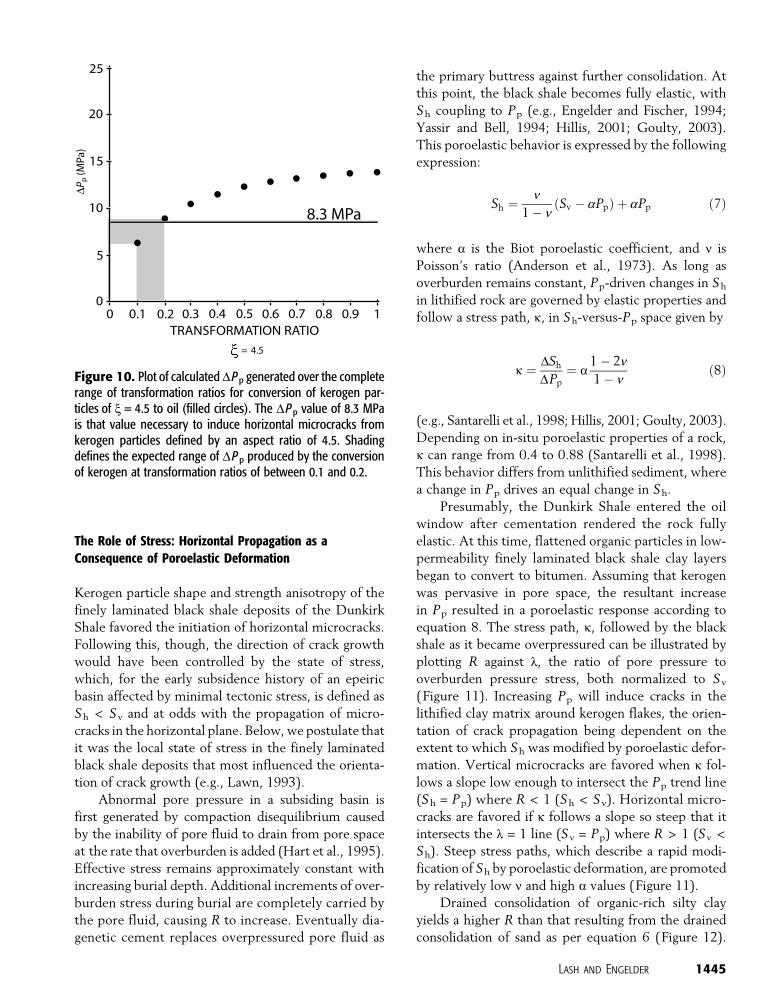
that for the inferred burial depth and stress conditions
of the Dunkirk Shale outlined above, kerogen parti-
cles with x < 4.5 could not have originated micro-
cracks unless TR � 0.2 (Figure 10).
Figure 9. Plot of calculated DPp generated over thecomplete range of transformation ratios for observedx values of Dunkirk Shale kerogen particles (filled cir-cles). Based on Lehner’s (1991) analytical approach andassumes no production of residual coke as reflectedby the relatively high HI values of Dunkirk Shale sam-ples. The DPp values of 16.5, 2.3, and 1.2 MPa (graylines) are those necessary to induce horizontal micro-cracks in the Dunkirk Shale for kerogen-bitumen in-clusions defined by aspect ratios of 2.5, 15, and 30,respectively. Shading defines the expected range ofDPp produced by kerogen conversion at transforma-tion ratios of between 0.1 and 0.2.
1444 Geologic Note
The Role of Stress: Horizontal Propagation as aConsequence of Poroelastic Deformation
Kerogen particle shape and strength anisotropy of the
finely laminated black shale deposits of the Dunkirk
Shale favored the initiation of horizontal microcracks.
Following this, though, the direction of crack growth
would have been controlled by the state of stress,
which, for the early subsidence history of an epeiric
basin affected by minimal tectonic stress, is defined as
Sh < Sv and at odds with the propagation of micro-
cracks in the horizontal plane. Below, we postulate that
it was the local state of stress in the finely laminated
black shale deposits that most influenced the orienta-
tion of crack growth (e.g., Lawn, 1993).
Abnormal pore pressure in a subsiding basin is
first generated by compaction disequilibrium caused
by the inability of pore fluid to drain from pore space
at the rate that overburden is added (Hart et al., 1995).
Effective stress remains approximately constant with
increasing burial depth. Additional increments of over-
burden stress during burial are completely carried by
the pore fluid, causing R to increase. Eventually dia-
genetic cement replaces overpressured pore fluid as
the primary buttress against further consolidation. At
this point, the black shale becomes fully elastic, with
Sh coupling to Pp (e.g., Engelder and Fischer, 1994;
Yassir and Bell, 1994; Hillis, 2001; Goulty, 2003).
This poroelastic behavior is expressed by the following
expression:
Sh ¼ n1 � n
ðSv � aPpÞ þ aPp ð7Þ
where a is the Biot poroelastic coefficient, and n is
Poisson’s ratio (Anderson et al., 1973). As long as
overburden remains constant, Pp-driven changes in Sh
in lithified rock are governed by elastic properties and
follow a stress path, k, in Sh-versus-Pp space given by
k ¼ DSh
DPp¼ a
1 � 2n1 � n
ð8Þ
(e.g., Santarelli et al., 1998; Hillis, 2001; Goulty, 2003).
Depending on in-situ poroelastic properties of a rock,
k can range from 0.4 to 0.88 (Santarelli et al., 1998).
This behavior differs from unlithified sediment, where
a change in Pp drives an equal change in Sh.
Presumably, the Dunkirk Shale entered the oil
window after cementation rendered the rock fully
elastic. At this time, flattened organic particles in low-
permeability finely laminated black shale clay layers
began to convert to bitumen. Assuming that kerogen
was pervasive in pore space, the resultant increase
in Pp resulted in a poroelastic response according to
equation 8. The stress path, k, followed by the black
shale as it became overpressured can be illustrated by
plotting R against l, the ratio of pore pressure to
overburden pressure stress, both normalized to Sv
(Figure 11). Increasing Pp will induce cracks in the
lithified clay matrix around kerogen flakes, the orien-
tation of crack propagation being dependent on the
extent to which Sh was modified by poroelastic defor-
mation. Vertical microcracks are favored when k fol-
lows a slope low enough to intersect the Pp trend line
(Sh = Pp) where R < 1 (Sh < S v). Horizontal micro-
cracks are favored if k follows a slope so steep that it
intersects the l = 1 line (Sv = Pp) where R > 1 (Sv <
Sh). Steep stress paths, which describe a rapid modi-
fication of Sh by poroelastic deformation, are promoted
by relatively low n and high a values (Figure 11).
Drained consolidation of organic-rich silty clay
yields a higher R than that resulting from the drained
consolidation of sand as per equation 6 (Figure 12).
Figure 10. Plot of calculated DPp generated over the completerange of transformation ratios for conversion of kerogen par-ticles of x = 4.5 to oil (filled circles). The DPp value of 8.3 MPais that value necessary to induce horizontal microcracks fromkerogen particles defined by an aspect ratio of 4.5. Shadingdefines the expected range of DP p produced by the conversionof kerogen at transformation ratios of between 0.1 and 0.2.
Lash and Engelder 1445
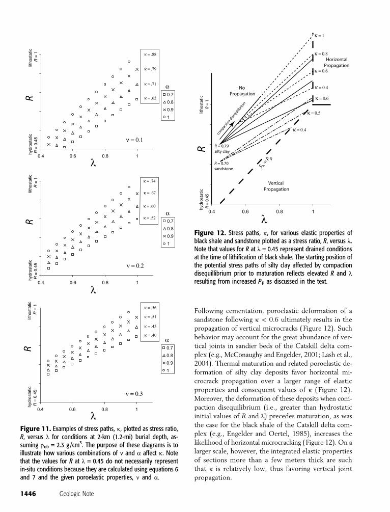
Following cementation, poroelastic deformation of a
sandstone following k < 0.6 ultimately results in the
propagation of vertical microcracks (Figure 12). Such
behavior may account for the great abundance of ver-
tical joints in sandier beds of the Catskill delta com-
plex (e.g., McConaughy and Engelder, 2001; Lash et al.,
2004). Thermal maturation and related poroelastic de-
formation of silty clay deposits favor horizontal mi-
crocrack propagation over a larger range of elastic
properties and consequent values of k (Figure 12).
Moreover, the deformation of these deposits when com-
paction disequilibrium (i.e., greater than hydrostatic
initial values of R and l) precedes maturation, as was
the case for the black shale of the Catskill delta com-
plex (e.g., Engelder and Oertel, 1985), increases the
likelihood of horizontal microcracking (Figure 12). On a
larger scale, however, the integrated elastic properties
of sections more than a few meters thick are such
that k is relatively low, thus favoring vertical joint
propagation.
Figure 11. Examples of stress paths, k, plotted as stress ratio,R, versus l for conditions at 2-km (1.2-mi) burial depth, as-suming rob = 2.3 g/cm3. The purpose of these diagrams is toillustrate how various combinations of n and a affect k. Notethat the values for R at l = 0.45 do not necessarily representin-situ conditions because they are calculated using equations 6and 7 and the given poroelastic properties, n and a.
Figure 12. Stress paths, k, for various elastic properties ofblack shale and sandstone plotted as a stress ratio, R, versus l.Note that values for R at l = 0.45 represent drained conditionsat the time of lithification of black shale. The starting position ofthe potential stress paths of silty clay affected by compactiondisequillibrium prior to maturation reflects elevated R and lresulting from increased PP as discussed in the text.
1446 Geologic Note
In sum, the initiation of horizontal microcracking
of the finely laminated, organic-rich deposits of the
lower part of the Dunkirk Shale induced by catagenesis
is favored by three material properties of these rocks:
(1) abundant flat kerogen grains oriented parallel to
layering; (2) a marked layer-perpendicular strength
anisotropy in large part caused by the laminated nature
of the rock; and (3) the tight, strongly oriented planar
clay-grain fabric capable of sustaining Pp generated by
the conversion of kerogen to bitumen and oil. The level
of internal pressure necessary to initiate horizontal
open-mode microcracks is a function of the first factor.
That is, the flatter the kerogen particle, the lower the
Pp necessary to create an effective tensile stress in the
vertical direction. However, even if the requisite Pp
is produced during catagenesis, it cannot be allowed
to drain off. Indeed, the moderately bioturbated, rela-
tively porous shale that dominates the upper half of
the Dunkirk Shale likely remained drained during
catagenesis, thereby precluding the initiation of hori-
zontal microcracks. The tight microfabric of the lami-
nated shale, inherited from its depositional and early
diagenetic history, sustained Pp, the crack-driving stress,
around pervasive kerogen particles converting to
bitumen, favoring the initiation of horizontal micro-
cracks, especially from the flattest kerogen grains. The
level of Pp loss caused by microcracking appears to
have been less than that generated by the conversion of
kerogen to bitumen, thereby enabling the rock to
pressurize. Internal pressure may have been further
sustained by the filling of fractures by bitumen (e.g.,
Anissimov, 2001).
Following initiation, the orientation of crack propa-
gation is controlled largely by in-situ stress. Over-
pressure development and resultant poroelastic defor-
mation of the low-permeablility, finely laminated black
shale deposits lower in the Dunkirk Shale reoriented
the in-situ stress to a configuration in which Sv < Sh,
thereby encouraging the widespread propagation of
horizontal microcracks. Our calculations suggest that
the local crack-driving stress induced by the poro-
elastic behavior of the organic-rich Dunkirk Shale alone
could have initiated the observed horizontal micro-
cracks. Still, preferential microcracking of the finely
laminated shale suggests that material properties, in-
cluding strength anisotropy and kerogen particle shape,
were instrumental in initiating the horizontal cracks
in these rocks. Poroelastic behavior and related switch-
ing of the in-situ stress field likely was enhanced by
compaction disequilibrium. Indeed, a review of equa-
tion 3 indicates that an increase of R arising from
compaction disequilibrium and consequent poroelastic
coupling of Sh to Pp would have reduced the DPp in-
crement produced by catagenesis necessary to initiate
horizontal microcracks.
CONCLUSIONS
Horizontal microcracks, most filled with bitumen, are
exclusive to clay layers in the finely laminated, organic
carbon-rich lower half of the Dunkirk Shale. The clay
layers are defined by a tight, strongly oriented, platy
grain microfabric produced by gravitational compac-
tion early in the diagenetic history of these deposits.
Note that moderately bioturbated, less organic-rich
shales higher in the Dunkirk, defined by a more open
or random microfabric, lack horizontal microcracks.
Horizontal microcracking under a basinal stress field in
which the greatest principal stress was vertical can be
explained by (1) a marked compaction-induced layer-
perpendicular strength anisotropy and abundant flat-
tened kerogen grains, both vital to the initiation of
microcracks in laminated shale in the lower half of
the Dunkirk Shale and (2) poroelastic deformation
of these low-permeability deposits pressurized by the
conversion of kerogen to bitumen and the consequent
establishment of a local in-situ stress field favorable to
the propagation of the microcracks in the horizontal
plane.
Natural fractures increase the effective permeabili-
ty of otherwise tight source rocks. Horizontal micro-
cracks produced early in the catagenic history of a
source rock, like those documented in this article,
would enhance lateral primary migration of hydrocar-
bons, especially in the updip direction, and may con-
nect with vertical joints and/or faults, further facili-
tating primary and secondary migration. Horizontal
microcracking of impermeable organic-rich horizons
in shale-dominated basinal sequences would enhance
fluid movement through these deposits; immediately
over- and underlying unfractured intervals, however,
may serve as aquitards, thereby maintaining elevated
formation pressures in the fractured rocks.
REFERENCES CITED
Anderson, R. A., D. S. Ingram, and A. M. Zanier, 1973, Deter-mining fracture pressure gradients from well logs: Journal ofPetroleum Technology, v. 26, p. 1259–1268.
Anissimov, L., 2001, Overpressure phenomena in the Precaspianbasin: Petroleum Geoscience, v. 7, p. 389–394.
Lash and Engelder 1447
Breckels, I. M., and H. A. van Eekelen, 1982, Relationship betweenhorizontal stress and depth in sedimentary basins: Journal ofPetroleum Technology, v. 34, p. 2191–2198.
Capuano, R. M., 1993, Evidence of fluid flow in microcracks ingeopressured shales: AAPG Bulletin, v. 77, p. 1303–1314.
Comer, J. B., and H. H. Hinch, 1987, Recognizing and quantifyingexpulsion of oil from the Woodford Formation and age-equivalent rocks in Oklahoma and Arkansas: AAPG Bulletin,v. 71, p. 844–858.
Costin, L. S., 1981, Static and dynamic behaviour of oil shale, inS. W. Freiman, ed., Fracture mechanics of ceramics, rocks andconcrete: American Society of Testing Materials, Philadelphia,ASTM STP 745, p. 169–184.
Demaison, G. J., and G. T. Moore, 1980, Anoxic environments andoil source bed genesis: AAPG Bulletin, v. 64, p. 1179–1209.
Dewhurst, D. N., A. C. Aplin, J.-P. Sarda, and Y. Yang, 1998,Compaction-driven evolution of porosity and permeability innatural mudstones: An experimental study: Journal of Geo-physical Research, v. 103, p. 651–661.
du Rouchet, J., 1981, Stress fields, a key to oil migration: AAPGBulletin, v. 65, p. 445–459.
Engelder, T., and M. P. Fischer, 1994, Influence of poroelasticbehavior on the magnitude of minimum horizontal stress, S h,in overpressured parts of sedimentary basins: Geology, v. 22,p. 949–952.
Engelder, T., and G. Oertel, 1985, The correlation between under-compaction and tectonic jointing within the Devonian Catskilldelta: Geology, v. 13, p. 863–866.
Ervine, W. R., and J. S. Bell, 1987, Subsurface in situ stress mag-nitudes from oil-well drilling records: An example from theVenture area, offshore eastern Canada: Canadian Journal ofEarth Science, v. 24, p. 1748–1759.
Espitalie, J., 1986, Use of T max as a maturation index for differenttypes of organic matter. Comparison with vitrinite reflectance,in J. Burrus, ed., Thermal modeling in sedimentary basins:Paris, Editions Technip, p. 475–496.
Finkbeiner, R. and M. D. Zoback, 1998, In-situ stress and porepressure in the south Eugene Island field, Gulf of Mexico:Society Petroleum Engineers– International Society for RockMechanics Eurock 98 Conference, Trondheim, Norway, July8–10, SPE Paper 47212, v. 1, p. 69–78.
Flugel, E., 1982, Microfacies analysis of limestones: Berlin, Springer-Verlag, 633 p.
Gaarenstroom, L., R. A. J. Tromp, M. C. de Jong, and A. M.Brandenburg, 1993, Overpressures in the central North Sea:Implications for trap integrity and drilling safety, in J. R.Parker, ed., Petroleum geology of northwestern Europe: Pro-ceedings of the 4th Conference, Geological Society (London),p. 1305–1313.
Goulty, N. R., 2003, Reservoir stress path during depletion ofNorwegian chalk oilfields: Petroleum Geoscience, v. 9, p. 233–241.
Grauls, D. J., and J. M. Baleix, 1994, Role of overpressures and insitu stresses in fault-controlled hydrocarbon migration: A casestudy: Marine and Petroleum Geology, v. 11, p. 734–742.
Harrold, T. W. D., R. E. Swarbrick, and N. R. Goulty, 1999, Porepressure estimation from mudrock porosities in Tertiarybasins, southeast Asia: AAPG Bulletin, v. 83, p. 1057–1067.
Hart, B. S., P. B. Flemings, and A. Deshpande, 1995, Porosity andpressure: Role of compaction disequilibrium in the develop-ment of geopressures in a Gulf Coast Pleistocene basin: Ge-ology, v. 23, p. 45–48.
Hillis, R. R., 2001, Coupled changes in pore pressure and stress inoil fields and sedimentary basins: Petroleum Geoscience, v. 7,p. 419–425.
Jarvie, D. M., and L. L. Lundell, 2001, Kerogen type and thermal
transformation of organic matter in the Miocene MontereyFormation, in C. M. Isaacs and J. Rulkotter, eds., The Mon-terey Formation: From rocks to molecules: New York, Co-lumbia University Press, p. 268–295.
Karig, D. E., and G. Hou, 1992, High-stress consolidation experi-ments and their geological implications: Journal of Geophys-ical Research, v. 97, p. 289–300.
Karig, D. E., and J. Morgan, 1994, Tectonic deformation: Stresspaths and strain history, in A. Maltman, ed., The geological de-formation of sediments: London, Chapman & Hall, p. 167–204.
Katsube, T. J., and M. A. Williamson, 1998, Shale petrophysi-cal characteristics: Permeability history of subsiding shales, inJ. Scheiber, W. Zimmerle, and P. Sethi, eds., Shales and mud-stones, I: Stuttgart, E. Schwiezerbart’sche, p. 69–91.
Kattai, V., 1994, Nature of the solid bitumen lenses in the lowerPalaeozoic sedimentary rocks in northern Estonia: Oil Shale,v. 11, p. 100.
Krushin, J. T., 1997, Seal capacity of non-smectite shale, in R. C.Surdam, ed., Seals, traps, and the petroleum system: AAPGMemoir 67, p. 31–67.
Lambe, T. W., and R. V. Whitman, 1969, Soil mechanics: NewYork, John Wiley, 553 p.
Langford, F. F., and M.-M. Blanc-Valleron, 1990, Interpreting Rock-Eval pyrolysis data using graphs of pyrolizable hydrocarbonsvs. total organic carbon: AAPG Bulletin, v. 74, p. 799–804.
Lash, G. G., and D. R. Blood, 2004, Origin of shale fabric by me-chanical compaction of flocculated clay: Evidence from theUpper Devonian Rhinestreet Shale, western New York: Jour-nal of Sedimentary Research, v. 74, p. 110–116.
Lash, G. G., S. Loewy, and T. Engelder, 2004, Preferential jointingof Upper Devonian black shale, Appalachian plateau, U.S.A.:Evidence supporting hydrocarbon generation as a joint-drivingmechanism, in J. Cosgrove and T. Engelder, eds., The ini-tiation, propagation, and arrest of joints and other fractures:Geological Society (London) Special Publication 231, p. 129–151.
Lawn, B., 1993, Fracture of brittle solids, 2d ed.: Cambridge, Cam-bridge University Press, 378 p.
Lehner, F. K., 1991, Pore-pressure induced fracturing of petroleumsource rocks. Implications for primary migration, in G. Ima-risio, M. Frias, and J. M. Bemtgen, eds., The European Oiland Gas Conference, a multidisciplinary approach in explora-tion and production R&D proceedings: London, Graham andTrotman, p. 142–154.
Lewan, M. D., 1987, Petrographic study of primary petroleummigration in the Woodford Shale and related rocks, in B.Doligez, ed., Migration of hydrocarbons in sedimentary basins:Paris, Editions Technip, p. 113–130.
Lewan, M. D., M. E. Henry, D. K. Higley, and J. K. Pitman, 2002,Material-balance assessment of the New Albany–Chesterianpetroleum system of the Illinois basin: AAPG Bulletin, v. 86,p. 745–778.
Littke, R., D. R. Baker, and D. Leythaeuser, 1988, Microscopic andsedimentologic evidence for the generation and migration ofhydrocarbons in Toarcian source rocks of different maturities:Organic Geochemistry, v. 13, p. 549–559.
Lomando, A. J., 1992, The influence of solid reservoir bitumen onreservoir quality: AAPG Bulletin, v. 76, p. 1137–1152.
Marquez, X. M., and E. W. Mountjoy, 1996, Microcracks due tooverpressures caused by thermal cracking in well-sealed UpperDevonian reservoirs, deep Alberta basin: AAPG Bulletin, v. 80,p. 570–588.
McConaughy, D. T., and T. Engelder, 2001, Joint initiation in bed-ded clastic rocks: Journal of Structural Geology, v. 23, p. 203–221.
Meissner, F. F., 1978, Petroleum geology of the Bakken Formation,
1448 Geologic Note
Williston basin, North Dakota and Montana: Williston BasinSymposium, Montana Geological Society, 24th Annual Con-ference, p. 207–227.
Momper, J. A., 1978, Oil migration limitations suggested by geo-logical and geochemical considerations, in W. H. Roberts andR. Cordell, eds., Chemical constraints on petroleum migration:AAPG Continuing Short Course Notes Series 8, B1–B60.
O’Brien, N. R., and R. M. Slatt, 1990, Argillaceous rock atlas: NewYork, Springer-Verlag, 141 p.
Ozkaya, I., 1988, A simple analysis of oil-induced fracturing insedimentary rocks: Marine and Petroleum Geology, v. 5,p. 293–297.
Pitman, J. K., L. C. Price, and J. A. LeFever, 2001, Diagenesis andfracture development in the Bakken Formation, Willistonbasin: Implications for reservoir quality in the middle member:U.S. Geological Survey Professional Paper 1653, 19 p.
Santarelli, R. J., J. T. Tronvoll, M. Svennekjaer, H. Skele, R.Henriksen, and R. K. Bratli, 1998, Reservoir stress path: Thedepletion and the rebound: Society Petroleum Engineers–International Society for Rock Mechanics Eurock 98 Confer-ence, Trondheim, Norway, July 8–10, SPE Paper 47350, v. 2,p. 203–209.
Schmidt, R. A., 1977, Fracture mechanics of oil shale-unconfinedfracture toughness, stress corrosion cracking, and tension test
results, in F.-D. Wang and G. B. Clark, eds., Energy resourcesand excavation technology: Proceedings, 18th U.S. Sympo-sium on Rock Mechanics: Golden, Colorado, Colorado Schoolof Mines, p. 2A2-1–2A2-6.
Snarsky, A. N., 1962, Die primare migration des erdols: FreibergerForschungsch, v. C123, p. 63–73.
Swarbrick, R. E., M. J. Osborne, and G. S. Yardley, 2002,Comparison of overpressure magnitude resulting from themain generating mechanisms, in A. R. Huffman and G. L.Bowers, eds., Pressure regimes in sedimentary basins and theirprediction: AAPG Memoir 76, p. 1–12.
Talukdar, S., O. Gallango, C. Vallejos, and A. Ruggiero, 1987,Observations on the primary migration of oil in the La Lunasource rocks of the Maracaibo Basin, Venezuela, in B. Doligez,ed., Migration of hydrocarbons in sedimentary basins: Paris,Editions Technip, p. 59–78.
Tissot, B., and D. H. Welte, 1984, Petroleum formation andoccurrence: New York, Springer-Verlag, 699 p.
Vernik, L., 1994, Hydrocarbon-generation– induced microcrackingof source rocks: Geophysics, v. 59, p. 555–563.
Yassir, N. A., and J. S. Bell, 1994, Relationships between porepressure, stresses, and present-day geodynamics in the Sco-tian Shelf, offshore eastern Canada: AAPG Bulletin, v. 78,p. 1863–1880.


![Untitled Document [geomuseu.ist.utl.pt] exercises... · Web viewIntrodução à Geologia de Reservatórios/ Introduction to Reservoir Geology Exercise 2 Subject: Diagenesis, Catagenesis,](https://static.documents.pub/doc/80x56/61295c37223d1d1b1b2633cf/untitled-document-exercises-web-view-introduo-geologia-de-reservatrios.jpg)


