RP 170 AN APPARATUS AND METHOD FOR DETERMINING THE COMPRESSIBILITY OF A GAS AND THE CORRECTION FOR "SUPERCOMPRESSIBILITY" By Howard S. Bean ABSTRACT Boyle's law for gases states that the density is directly proportional to the absolute static pressures. All gases depart from this law to some extent, and this is especially true of the industrial fuel gases known as natural gas, for which the departure may be as much as 7 or 8 per cent for a pressure range of 1 to 40 atmospheres. When these gases are metered at pressures of over 5 or 6 atmospheres this departure from Boyle's law becomes important, and a correc- tion must be made to the meter indications by the introduction of a term called the "supercompressibility factor." In the experimental procedure for determining this factor a sample of gas is collected at high pressure in a steel cylinder of known capacity. Successive small portions of this sample are withdrawn into a burette where their volumes at atmospheric pressure are determined. This is continued until the whole sample has been reduced to atmospheric pressure. The sum of all these volumes at atmospheric pressure is then compared with the volume to which the initial sample of gas would have expanded if it had followed Boyle's law as the pressure was reduced to atmospheric. The derivation of the equation used in computing the factor from the observa- tional data is given, and the steps to be taken in apptying this equation are enumerated. Experience has indicated that the factors thus determined will be correct within ±0.002. Based on the experience gained with the use of the apparatus described several factors of special interest are discussed. Other methods of determining the supercompressibility factor are also mentioned. CONTENTS page I. Introduction 645 II. Description of the apparatus 648 1. List of parts 648 III. Adjustments 650 IV. Experimental procedure for making a test 651 V. Method of computing the supercompressibility factor 653 1. Constants of the apparatus 653 2. Observed quantities 653 3. Deduced quantities 653 VI. Supplementary notes 657 1 Volume of tube between valve 2 and cock 3 657 2. Relation between volumes of cylinder and burette 657 3. Precautions to be observed in the use of the constant tem- perature bath 658 4. Effects of moisture in connections 658 5. Comparison of this and other methods of determining the supercompressibility factor 659 6. Additional notes on the operation and construction of the apparatus 661 I. INTRODUCTION When an orifice or a Venturi tube is employed as a meter for determining the rate of flow of a fluid along a pipe line, the primary quantity to be observed is the pressure drop or differential set up at the meter ; but this differential depends on the density of the fluid as well as on the rate of flow, and in order to translate the observed differentials into rates of flow and interpret the readings of the meter, 645
Transcript
RP 170
AN APPARATUS AND METHOD FOR DETERMINING THECOMPRESSIBILITY OF A GAS AND THE CORRECTIONFOR "SUPERCOMPRESSIBILITY"
By Howard S. Bean
ABSTRACT
Boyle's law for gases states that the density is directly proportional to theabsolute static pressures. All gases depart from this law to some extent, andthis is especially true of the industrial fuel gases known as natural gas, for whichthe departure may be as much as 7 or 8 per cent for a pressure range of 1 to40 atmospheres. When these gases are metered at pressures of over 5 or 6atmospheres this departure from Boyle's law becomes important, and a correc-tion must be made to the meter indications by the introduction of a term called
the "supercompressibility factor."
In the experimental procedure for determining this factor a sample of gas is
collected at high pressure in a steel cylinder of known capacity. Successivesmall portions of this sample are withdrawn into a burette where their volumesat atmospheric pressure are determined. This is continued until the wholesample has been reduced to atmospheric pressure. The sum of all these volumesat atmospheric pressure is then compared with the volume to which the initial
sample of gas would have expanded if it had followed Boyle's law as the pressurewas reduced to atmospheric.The derivation of the equation used in computing the factor from the observa-
tional data is given, and the steps to be taken in apptying this equation areenumerated. Experience has indicated that the factors thus determined will becorrect within ±0.002.Based on the experience gained with the use of the apparatus described several
factors of special interest are discussed. Other methods of determining thesupercompressibility factor are also mentioned.
CONTENTS pageI. Introduction 645
II. Description of the apparatus 6481. List of parts 648
III. Adjustments 650IV. Experimental procedure for making a test 651V. Method of computing the supercompressibility factor 653
1. Constants of the apparatus 6532. Observed quantities 6533. Deduced quantities 653
VI. Supplementary notes 6571
.
Volume of tube between valve 2 and cock 3 6572. Relation between volumes of cylinder and burette 6573. Precautions to be observed in the use of the constant tem-
perature bath 6584. Effects of moisture in connections 6585. Comparison of this and other methods of determining the
supercompressibility factor 6596. Additional notes on the operation and construction of the
apparatus 661
I. INTRODUCTION
When an orifice or a Venturi tube is employed as a meter for
determining the rate of flow of a fluid along a pipe line, the primaryquantity to be observed is the pressure drop or differential set up atthe meter ; but this differential depends on the density of the fluid aswell as on the rate of flow, and in order to translate the observeddifferentials into rates of flow and interpret the readings of the meter,
645
646 Bureau of Standards Journal of Research [V01.4
the density must be taken into account. With liquids, this is asimple matter; for the density of a liquid is so little affected by anyordinary changes of pressure and temperature that it may, in practice,
be treated as a constant and determined, once for all, at any convenientpressure and temperature. But if the fluid in question is a gas, its
density varies with the temperature and static pressure in the pipeline, and the interpretation of the readings of the differential becomesmore complicated.
It would be advantageous to have a gas densimeter or gravitometerthat could be attached directly to the line, or inserted in it and readfrom outside ; but in the absence of such an instrument, it is necessaryto observe the temperature and static pressure of the gas, simul-taneously with the differential, so that the density in the pipe may becomputed from the density measured near atmospheric pressure bymeans of a specific gravity balance or by some equivalent method.
In many instances, it is sufficiently accurate for commercial orifice
meter practice to make the computation by using the ideal gas equation
7P= R CD
in which p is the density of the gas at the absolute static pressure Pand the absolute temperature T; and R is the so-called gas constantfor the given gas, the numerical value of R depending on the units bywhich p, P, and T are measured.
If the density has been found by experiment to be p at atmosphericpressure P and at the temperature TQ , the density p at any other pres-
sure P and temperature T may be found from the equation
P PT,P T W
Po ±o 1
which follows from equation (1); and if the change of pressure takesplace at constant temperature so that T= T , this reduces to
H .
(3>
so that the computation of p from p is a very simple matter. Equation(3) is merely a statement of Boyle's law, from which our ordinaryideas on the compressibility of gases are derived.
But in reality, no gas foliows equation (1) exactly, and the foregoing-
method is not always adequate to the constantly increasing demandsfor accuracy in commercial measurements. Different gases departfrom Boyle 's law by different amounts, and both the amount and thedirection of the departure depend on the temperature. With mostgases, at ordinary temperatures, the density increases with rising-
pressure somewhat faster than is indicated by equation (3) or, in otherwords, the gas is more compressible than if it followed Boyle's lawexactly; and this behavior may be represented by writing equation
(3) in the modified form
£Po=yw (4)p
in which y is a numerical factor slightly greater than 1.00. 1
1 This statement is true when restricted to most natural gases at the temperatures and pressures ordinarilyencountered in commercial work. From a general standpoint there are many exceptions to it, one beingthat for almost all gases the direction of the departure from Boyle's law will be the reverse of that stated,
and the value of y will be less than 1.00 at sufficiently high tenperatures or under very high pressures.Another exception is that for some gases, notably hydrogen and helium at ordinary temperature, the valueof y is less than 1.
Bean] Correction for Supercompressibility 647
This excess of compressibility over what is indicated by Boyle'slaw may be called the "supercompressibility," and the quantity y will
be designated as the " supercompressibility factor."
For air at 60° F., the value of y at the absolute pressure P = 600lbs. /in.
2is about 1.014. Hence, even at so high a pressure as this, the
computation of the density by means of Boyle 's law would involve anerror of only 1.4 per cent. And since the orifice meter equations,
which need not be discussed here, 2 contain only the square root of the
density, the resulting error in the rate of flow deduced from orifice
meter readings would be only about 0.7 per cent, an amount whichwould be negligible in many cases.
With most natural gases, however, the departures from Boyle'slaw are much greater than with air, and the use of equation (3) with-
out including the correction factor y may result in serious errors, if
the gas is metered at high pressure. For example, in the case of a
natural gas for which experimental data will be given later (Table 1),
the value of the supercompressibility factor, at 32° F. and 210lbs. /in.
2 absolute pressure, was found to be nearly 1.04, and hence the
density was nearly 4 per cent greater than that computed from the
density at atmospheric pressure by means of Boyle's law. At 600lbs. /in.
2 the error would probably have been nearly three times as
great.
So long as the pressures at which gases were metered were com-paratively low, such as 75 lbs. /in.
2 absolute, or less, errors of the sort
now in question were seldom or never of any commercial importance
;
but the increasing tendency to raise the pressures on transmissionlines has necessarily led to the use of orifice meters at higher pressures,
and instances have been reported of measurements at pressures be-tween 700 and 1,000 lbs. /in.
2. This rise in the working pressures,
coupled with the increasing demand for more accurate metering, hasmade supercompressibility a subject of considerable commercialimportance.For several years the Bureau of Standards has been cooperating
in researches on orifice meters conducted by the committee on gasmeasurement of the natural gas department of the American GasAssociation. The experiments have been made with natural gas fromseveral fields, and when it was decided to carry on experiments at pipe-line pressures of 200 lbs. /in.
2 and over, it became necessary to prepareapparatus for determining the supercompressibility factors whichwould be needed in reducing the observations on the various gases.
A description of the apparatus made for this purpose, the mode of
operation, and a method of computing the supercompressibility factorfrom the data obtained are herein presented.The general outline of the experimental method, which is a classical
one, was suggested to the writer as suitable to the purpose in hand byDr. Edgar Buckingham, who also made some useful suggestions regard-ing methods of computation. Acknowledgement is likewise due to
J. R. Fay for assistance in the preparation of the apparatus. ,
Before going into details it may be stated that the principle of themethod is, briefly, as follows: After a sample of the gas has beencollected at high pressure in a steel cylinder of known capacity,successive small portions of the sample are withdrawn into a glass
2 See Sees. X, XI, and XXVI of B. S. Research Paper No. 49, Discharge Coefficientsfof Square-EdgedOrifices for Measuring the Flow of Air.
101062°—30 4
648 Bureau of Standards Journal of Research [Vol. 4
burette where their volumes can be determined at atmospheric pres-
sure. This is continued until the whole sample has been reduced to
atmospheric pressure, and the sum of all the volumes at atmosphericpressure is then compared with the volume to which the initial knownvolume of gas would have expanded if it had been reduced to atmos-pheric pressure in accordance with Boyle's law.
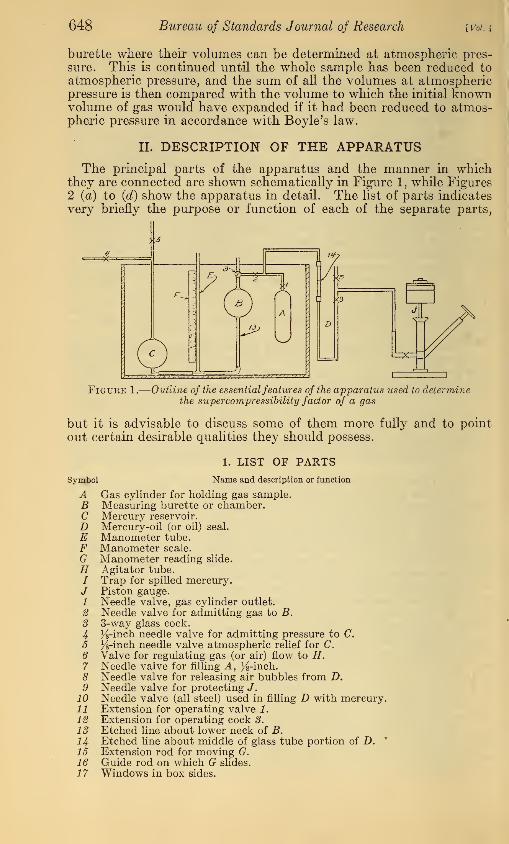
II. DESCRIPTION OF THE APPARATUS
The principal parts of the apparatus and the manner in whichthey are connected are shown schematically in Figure 1 , while Figures2 (a) to (d) show the apparatus in detail. The list of parts indicates
very briefly the purpose or function of each of the separate parts,
Figure 1.
—
Outline of the essential features of the apparatus used to determinethe supercompressibility factor of a gas
but it is advisable to discuss some of them more fully and to point
out certain desirable qualities they should possess.
1. LIST OF PARTS
Symbol Name and description or function
A Gas cylinder for holding gas sample.B Measuring burette or chamber.C Mercury reservoir.
D Mercury-oil (or oil) seal.
E Manometer tube.F Manometer scale.
G Manometer reading slide.
H Agitator tube./ Trap for spilled mercury./ Piston gauge.1 Needle valve, gas cylinder outlet.
2 Needle valve for admitting gas to B.3 3-way glass cock.
4 K-inch needle valve for admitting pressure to C.5 %-inch needle valve atmospheric relief for C.6 Valve for regulating gas (or air) flow to H.7 Needle valve for filling A, %-inch.8 Needle valve for releasing air bubbles from D.9 Needle valve for protecting J.
10 Needle valve (all steel) used in filling D with mercury.11 Extension for operating valve 1.
12 Extension for operating cock 3.
13 Etched line about lower neck of B.
14 Etched line about middle of glass tube portion of D. p
15 Extension rod for moving G.16 Guide rod on which G slides.
17 Windows in box sides.
Bean) Correction for Super'compressibility 649
The cylinder A (fig. 1) need not be very large—the capacity~of theone used was about 36 cubic inches. It should be strong enough towithstand any pressure at which a test is to be started, withoutexpanding appreciably. While not essential, it is convenient to havethe cylinder provided with two valves to facilitate purging and filling.
The capacity of the cylinder, with valve 7 (fig. 2 (a)) closed, to theoutlet connection of valve 1 must be determined to an accuracy ofabout 1 part in 2,000.
The burette, B, should be of strong and fairly heavy glass. In theupper stem is the 3-way cock, 3, by means of which the burette maybe opened to the atmosphere for purging, or to the tube for connectingit with A. About the lower neck, a short distance below the body of
the burette, is an etched line, 13. The capacity of the burette, betweenthe 3-way cock as the upper limit and the etched line as the lowerlimit, must be determined to an accuracy of 1 in 2,000 or better. (Thepassages in the plug of the 3-way cock are not included in this volume.)
In order to determine the pressures with a satisfactory degree of
accuracy, it is necessary to use a dead-weight piston gauge J. (Fig.
1.) This, of course, will require that there be at hand the necessarysmall weights for reading pressures to 0.1 lbs. /in.
2. The use of the
piston gauge makes it necessary to have the trap D between it andthe gas cylinder A. This trap is essentially a special manometerabout 15 inches high, most of it being built up of suitable small pipefittings, but the upper 5 or 6 inches of the leg to which A is attachedconsists of a heavy gauge glass tube, thoroughly annealed and witheach end set into a special pipe coupling with Khotinsky cement.Around the center of the glass tube is an etched line (14)- The upperend of the other leg of the trap is provided with two valves, one oneither side of the tee to which J is connected. The length of this leg
is such that the offset of the tee is slightly below the level of the etchedline (14).
Small bore (% inch outside diameter) copper tubing is used to con-nect the trap with A, and enough bends are made in the trap end to
guard against putting an excessive strain on the glass. There is atee in the tube near the cylinder end, and the needle valve 2 is con-nected to one branch of this tee. The outlet of this valve is connectedto the burette B by as short a tube as possible. The capacity of the
tubing between valves 1 and 2 and the etched line 14 must be deter-
mined to the same absolute accuracy as the other volumes.The manometer tube E is the elongated offset of a tee. The run
of the tee forms a part of the line which joins the lower neck of B withthe reservoir C. It is desirable to have the tube E long enough to
extend even with or above the top of the atmospheric outlet from the
3-way cock 3.
The scale F, which is attached to or fastened beside the tube E,should be about 10 inches long with the zero near the center and the
graduations numbered both ways. In the apparatus now being
described, this scale is of glass with etched graduations and figures,
and the smallest division of the scale is Ko-inch.
The reservoir C should have a capacity about one-tenth larger thanthat of B. The relative elevations of B and C should be such that the
etched line 13, on the lower neck of B is level with or higher than the
opening into the upper neck of C. This upper neck of C is connected to
the valves 4 and 5. Through 4 gas or air under pressure ma}^ be ad-
mitted to C for forcing the mercury over into B while 5 is a relief valve.
650 Bureau of Standards Journal of Research
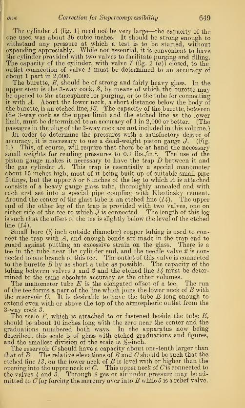
III. ADJUSTMENTS
[Vol. 4
After the apparatus has been assembled it is necessary to make afew adjustments before it is ready for use. The first is to adjust thequantity of sealing fluid in the trap D. This is very easy if only oil
is to be used in the trap, as it is only necessary to pump in oil from thepiston gauge until it stands about one-half inch above the etchedline 14. Air bubbles may be released through valve 8. Whenmercury is used with oil, this adjustment is not so easy. Mercuryis introduced into the trap through the all-steel needle valve 10
Section a-ad
Figure 2.
—
Apparatus used to determine the super'compressibility factor ofa gas
a, Plan view; b, elevation of right end showing assembly of the mercury-oil seal; c, front eleva-tion with side of tank removed; d, elevation of section a-a.
(Fig. 2 (a).) Enough mercury is used to fill the gauge glass side to
one-half inch above the etched line H, and to extend about 3 inches
up the other leg. The rest of the trap and the tube to the piston
gauge is filled with oil. The procedure used to do this is to fill bothlegs of the trap with mercury to a height of about 3 inches. Thenafter filling the piston gauge side with oil, valve 9 is closed and the
quantity of mercury needed to complete the filling of the gauge glass
side is introduced through valve 10. It is necessary to get out all the
air bubbles from the oil in the trap and tubing to the piston gauge.The use of mercury in one leg of the trap introduces an unbalanced
pressure on the piston gauge. It would be possible to have this
Bean] Correction for Supercompressibiliiy 651
column of mercury just balance the weight of the piston; but in theparticular apparatus being described a steel disk had been attachedto the plunger as a part of an arrangement to keep the plunger frombeing blown from the oil cylinder, and to balance this added weighton the plunger would have required an undesirably long trap. Insuch a case as the present one it is necessary to calibrate the combinedmercury-oii-piston gauge system, and this is done by applying air or
gas under pressure to the mercury side of the trap until the plunger,with all weights removed, begins to rise and the surface of the mercuryto fall. When the top of the mercury is in the plane of the etchedline 14 the amount of pressure being applied is read on a mercurymanometer temporarily connected ahead of the trap. On accountof the effects of friction and viscosity upon the plunger, it is best to
have the pressure increasing or decreasing very slowly and to read theauxiliary manometer quickly as the surface of the mercury in thetrap creeps past the etched line. The value used is then the averageobtained with falling and rising pressures.
The next adjustment to be made is that of the position of the scale
F, beside the manometer tube E. To do this the cock 8 and the valve5 are opened so that both B and C as well as E are open to the atmos-phere. Mercury is then poured into the system until C is full and
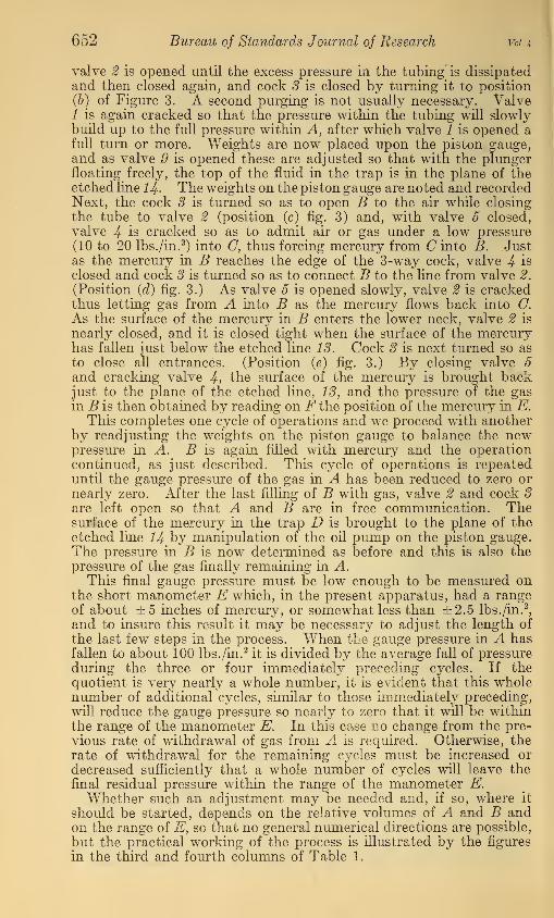
vertf vent
f
-®vent
(<*) (*>) (c)
Figure 3.
—
Successive positions of it core of the 8-way cock, 3
the surface of the mercury in the lower neck of B is exactly in theplane of the etched line 18. The scale is then moved up or downuntil its zero is exactly level with the surface of the mercury in E,and is finally fastened in that position. After completing thisadjustment, enough mercury is removed from the system so thatthe surface of the mercury in the lower neck of B will be one-fourthto three-eighths inch below the etched line 18. This is done so thatthe mercury may not foul the inner surface of the lower neck of Bright at the etched line, by standing there when the apparatus is notm use.
IV. EXPERIMENTAL PROCEDURE FOR MAKING A TESTWhen the foregoing adjustments have been made, the apparatus
is ready for use. The cylinder A is charged with the gas to be tested,put in place, and connected to the tube from D and 2. The tank inwhich the apparatus is mounted is filled with water and the waterstirred to insure a uniform temperature. To purge the tubing,cock 8 is turned so as to open the line from valve 2 to the atmos-phere, as shown by position (a) of Figure 3. With valves 2 and 9closed, valve 1 is cracked so that the pressure within the tubingbecomes equal or nearly equal to that in A. After closing valve 1,
652 Bureau of Standards Journal of Research Vol. A
valve 2 is opened until the excess pressure in the tubing is dissipatedand then closed again, and cock 3 is closed by turning it to position(b) of Figure 3. A second purging is not usually necessary. Valve1 is again cracked so that the pressure within the tubing will slowlybuild up to the full pressure within A, after which valve 1 is opened afull turn or more. Weights are now placed upon the piston gauge,and as valve .9 is opened these are adjusted so that with the plungerfloating freely, the top of the fluid in the trap is in the plane of theetched line 14- The weights on the piston gauge are noted and recordedNext, the cock 3 is turned so as to open B to the air while closing
the tube to valve 2 (position (c) fig. 3) and, with valve 5 closed,
valve 4 is cracked so as to admit air or gas under a low pressure
(10 to 20 lbs./in.2) into C, thus forcing mercury from (7 into B. Just
as the mercury in B reaches the edge of the 3-way cock, valve 4 is
closed and cock 3 is turned so as to connect B to the line from valve 2.
(Position (d) fig. 3.) As valve 5 is opened slowly, valve 2 is crackedthus letting gas from A into B as the mercury flows back into O.
As the surface of the mercury in B enters the lower neck, valve 2 is
nearly closed, and it is closed tight when the surface of the mercuryhas fallen just below the etched line 13. Cock 3 is next turned so as
to close all entrances. (Position (e) fig. 3.) By closing valve 5and cracking valve 4, the surface of the mercury is brought backjust to the plane of the etched line, 13, and the pressure of the gasin B is then obtained by reading on F the position of the mercury in E.
This completes one cycle of operations and we proceed with anotherby readjusting the weights on the piston gauge to balance the newpressure in A. B is again filled with mercury and the operationcontinued, as just described. This cycle of operations is repeateduntil the gauge pressure of the gas in A has been reduced to zero ornearly zero. After the last filling of B with gas, valve 2 and cock 3are left open so that A and B are in free communication. Thesurface of the mercury in the trap D is brought to the plane of theetched line 14 by manipulation of the oil pump on the piston gauge.The pressure in B is now determined as before and this is also thepressure of the gas finally remaining in A.
This final gauge pressure must be low enough to be measured onthe short manometer E which, in the present apparatus, had a rangeof about ±5 inches of mercury, or somewhat less than ±2.5 lbs. /in.
2,
and to insure this result it may be necessary to adjust the length of
the last few steps in the process. When the gauge pressure in A hasfallen to about 100 lbs. /in.
2it is divided by the average fall of pressure
during the three or four immediately preceding cycles. If thequotient is very nearly a whole number, it is evident that this wholenumber of additional cycles, similar to those immediately preceding,
will reduce the gauge pressure so nearly to zero that it will be withinthe range of the manometer E. In this case no change from the pre-
vious rate of withdrawal of gas from A is required. Otherwise, the
rate of withdrawal for the remaining cycles must be increased or
decreased sufficiently that a whole number of cycles will leave the
final residual pressure within the range of the manometer E.Whether such an adjustment may be needed and, if so, where it
should be started, depends on the relative volumes of A and B andon the range of E, so that no general numerical directions are possible,
but the practical working of the process is illustrated by the figures
in the third and fourth columns of Table 1.
Bean] Correction for Supercompressibility 653
V. METHOD OF COMPUTING THE SUPERCOMPRESSIBILITYFACTOR
In developing the equations needed for the computations, thefollowing notation and definitions will be employed.
1. CONSTANTS OF THE APPARATUS
ya = the volume of the cylinder A and the adjacent tubing, out to thevalve 2 and the etched mark 14-
y6= the volume of the burette, from the mark 18 to the plug of cock3 when closed.
Only the ratio of these volumes appears in the final equa-tion, so that their values may be expressed in terms of
any convenient unit.
K (lbs. /in.2) = the trap constant.
It is the gas pressure that must be applied at the top of the trap in
order to force the mercury surface down to the mark 14 whenthe piston of the gauge is floating freely with all the weightsremoved. It is measured, once for all, on an auxiliary mercurycolumn, as described above under the heading "Adjustments,"and then expressed in lbs. /in.
2.
2. OESERVED QUANTITIES
W (lbs./in.2) = the pressure due to the weights on the piston gauge.
It is the total added weight in pounds divided by the cross sec-
tion of the piston in square inches. For convenience, each of
the movable weights should be marked with its equivalent in
terms of pressure, so that the value of W may be read directly.
B (inches Hg) = the barometer reading, corrected to 32° F.
p b (inches Hg) = the reading of the manometer E.For the highest possible accuracy, p b should also
be corrected to 32° F., but in most cases thatwould be a useless refinement.
t (° .F.) = the temperature of the water bath.
It is assumed that t remains sensibly constant throughoutthe complete set of measurements on any one sample of
gas collected in A. Before starting the observations,
time must be allowed for the newly introduced sampleto come to the temperature of the bath.
n = the number of cycles of operations in the whole set of measure-ments on the sample.
3. DEDUCED QUANTITIES
B s (lbs./in.2) = the barometric pressure expressed in pounds per square
inch.
The reduction is made by means of the relation
1 (inch Hg 32° F.) = 0.4912 (lbs./in.2) (5)
Pa (lbs./in.2) = the absolute pressure in the cylinder A and the adjoin-
ing tubing as far as the valve 2 and the mark 14, whenthe valve 1 is open.
Pa=W+K+B $ (6)
654 Bureau of Standards Journal of Research [voi.t
P b (lbs./in.2) = the absolute pressure in the burette.
P 6 = 0.4912 (B+p b) (7)
Vs= the volume that would be occupied by the mass of gas which fills
the cylinder and tubing at the pressure P a , if it were allowedto expand to atmospheric pressure.
y = the supercompressibility factor.
y is defined as the ratio of the actual density at Pa to the " theo-retical' ' density computed from the density at atmosphericpressure, on the assumption of Boyle's law.
If m denotes the initial mass of gas contained in the volume Va atthe pressure P a , we have the relation
actual density at P a=^r (8)* a
When expanded to the volume Vs which it occupies at the pressureB s , the gas has the density m/Vs ; and if it were then recompressed to
P a , its density computed from Boyle's law would be
m Ptheoretical density at P a — -=rr X -^ (9)
Hence we have, from the definition of y,
m fm'Pa\ VSB S
Va \VS
XBJ VaPa(10)
in which Va , P a , and B s are known, and it remains to find the value
Let subscript k be used to specify quantities referring to the kth.
cycle of operations: k may have any value from 1 to n, inclusive.
At the start of the kth cycle the pressure in the cylinder and tubingis (P a)k- The gas withdrawn into the burette fills the volume Vb
at the absolute pressure (P 6)*; and if its pressure were changed to
B s , its volume would be
v *=v*^jir(11)
for P b is always so nearly equal to the outside barometric pressure Bs
that the departure from Boyle's law over this small range of pressure is
entirely negligible.
Starting with the kth. cycle and proceeding through the nth andlast, the combined volume, at the pressure B s , of all the portions of
gas withdrawn into the burette is
v k+ v k+1 + +v n=^l(P b) k+(P b) k+1 + +(P 6)J
V k
=t2? & U2)Bs n
Bean] Correction for Supercompressibility 655
At the end of the nth cycle, the cylinder and tubing remain filled
with gas at the final pressure (P&)», and if this residual gas were also
brought to the pressure Bs , its volume would be
v^ Va^wf (13)
All the gas is now accounted for and we have
(Vs ) k = V k + V k+1 + + V n + Vr (14)
or by equations (12) and (13)
TO^^S^+K (P 6)»] (15)
and upon substituting this value in equation (10) we have
1
V* l£)LVa
Vh J.2P 6 +(P6)»1 (16)n J
as our final equation for computing the value of the supercompressi-bility factor at the pressure (P a ) k .
As already remarked, the volumes Va and Vb appear only as aratio, and it may be noted that the pressures also occur in bothnumerator and denominator of equation (16). Hence, they mightequally well have been expressed in inches of mercury instead of
pounds per square inch, the only requirement being that Pa and theP &'s shall be expressed in terms of the same unit.
The trap constant K and the volume ratio (Vb/Va ) having beendetermined once for all, the computation of y from the observed databy means of equation (16) may conveniently be carried out in thefollowing steps.
1. For each cycle of operations, compute the values of Pa and P 6
(equations (5), (6), and (7)).
2. Starting with the nth. or last value of P & , add to it the (n— l)thvalue of P & ; add to this sum the (n — 2)th value, and so on, thus finding
k
the successive values ofS P& for all the cycles, from the last to the first.n
3. Multiply each of these sums by the volume ratio (Vb/Va) and to
this product add the nth value of P 6 .
4. Divide each of the quantities thus obtained by the correspondingvalue of Pa . The quotient is the required value of y.
A sample set of observed and computed values is given in Table 1.
If the values of y are plotted against those of P a , and if a mean curveis drawn through the resulting band of points, it appears that valuesof y read from the curve will nowhere be in error by more than 0.002,
if the volume ratio was accurately determined. The value of s/yneeded in orifice meter computations will therefore be correct within 1
part in 1,000 and we may conclude that experiments of the sort fromwhich the data in Table 1 were obtained are amply precise for ordinary-
commercial purposes,
656 Bureau of Standards Journal of Research [Vol. 4
Table 1.
—
Compressibility test data
Sample collected at Daly station.Date of collection, August 1, 1928.
Pressure when collected, 210-pound gauge.
Barometer:At start, 29.42 at 72° F.At end, 29.44 at 73° F.
Barometer corrected to 32° F.:5=29.31 inches._BS =14.40 lbs./in.»
Test No. XX.Date of test, August 1, 1928.Test made by, H. S. B.
Boom temperature:69.8° F.73° F.
Trap constant, iT=+9.66 lbs./in.a
Volume ratio, IVF = 0.8672.
Observed values Computed values
k(cycle No.)
Bath tem-perature
W Pb Pbk
n Va n +(Pb)
Pa V
1
° F.32.1
Lbs./in.*
186.2174.6162.8151.2
139.8128.2116. 5104.7
93.080.769.056.9
44.431.718.96.1
Inches, Fig-0.56+.67-.32-.52
-.41-.26-.30-.26
-.05-.32-.22+.94
+1.16+1.10+1.18+3.61
Lbs.linl14.1214.7314.2414.14
14.2014.2714.2514.27
14.3714.2414.2914.86
14.9714.9414.9816.17
233.04218. 92204. 19
189. 95
175. 81161. 61147. 34133. 09
118. 82104.4590.2175.92
61.0646.0931.1516.17
202. 09189. 85177. 07164. 72
152. 46140. 15127. 77115. 42
103.0490. 5878.2365.84
52.9539.9727.0114.02
218. 26206. 02193. 24180. 89
168. 63156. 32143. 94131. 59
119. 21
106. 7594.4082.01
69.1256.1443.1830.19
Lbs. /in. 2
210. 26• 198.66
186.86175. 26
163. 86152. 26140. 56128. 76
117. 06104. 7693.0680.98
68.4655.7642.9630.16
1.0382__ 1.0373 1.0344 1.032
5 32.5 1.0296 . 1.0277 1.0248 1. 022
9 1.01810 1.01911 32.6 1.01412 1.013
13 1.01014 1.00715 1.00516 32.9 1.001
7.08
7.07
7 0&
7. OS
7.0*
\7.03
<o
^ 7.02.
%7.07
7.00
4//
// a
/ AsI06'
f
/ y// <?
&A^,^2\
^..**\a^
700 zoo 400 600 7GO
Abso/ute Gas Pressure inLhs.per S&. In.
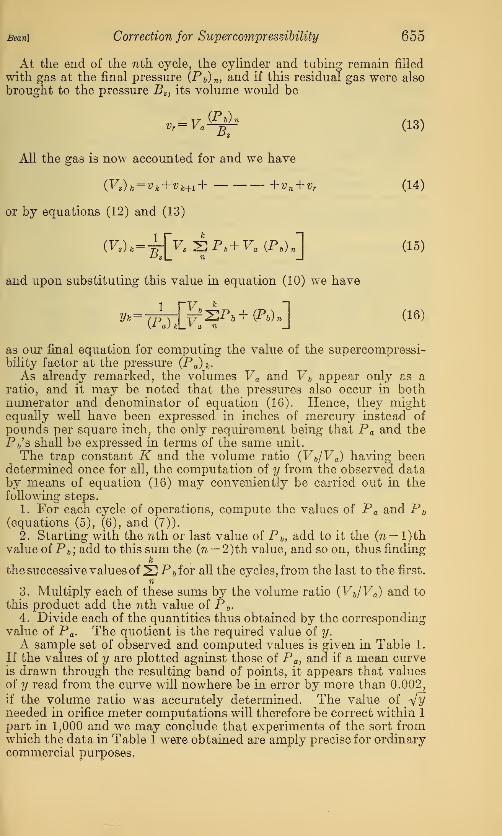
Figure 4.
—
The effects of temperature upon the supercompressibility correc-
tion factor
A large gas cylinder was filled with gas to a pressure of about 1,000 pounds, and samples of gaswere drawn from this cylinder when filling the sample cylinder, A. Analysis of this gas
showed it was 98.7 per cent methane,
Sean] Correction for Supercompressibility 657
VI. SUPPLEMENTARY NOTES
1. VOLUME OF TUBE BETWEEN VALVE 2 AND COCK 3
It may have been noted that the small volume of the tubing betweenvalve 2 and cock 3 which, for convenience, we will designate by u,
has been omitted from all calculations. It will now be shown thatthis omission has introduced no appreciable error. Before the buretteis filled with gas the first time, the tubing has been purged and thesection u remains full of gas at sensibly atmospheric pressure. When-ever the burette is being purged of gas, u will always remain full of
gas, regardless of whether cock 3 is turned so as to entrap the gastherein or not. (It is better practice to turn 3 so as to close off thetube from valve 2; then even if 2 should leak a little the gas will notescape unmeasured.)Now, the actual quantity or mass of gas entrapped within u during
each purging of B will depend upon the pressure in B at the time cock 3is turned to close off u. But this pressure will usually be very nearlyatmospheric if the experimental work is done with reasonable care.
Hence, the successive masses of gas within u will be sensibly equal,
and if they were exactly equal it would be unnecessary to considerthem at all. This applies to all fillings of B from 1 to (n—1), in-
clusive.
After the last or ?ith filling of B, all valves between A and B are left
open. If at this time it should happen that Pb were just equal to BSJ
this last mass of gas in u would be equal to the mass of gas in u just
prior to the first filling of B. Obviously, in this case no correction
would be needed.In most cases Pb will be either greater or less than Bs and the last
mass of gas in u will be correspondingly greater or less than the first.
In these cases it is true that, in principle, a correction should beapplied, and the amount of this correction could readily be deter-mined. But it is also evident that since this correction would beapplied to only the last of the n masses of gas taken from A into B,the correction will have no sensible influence upon the results, if thevolume of u is small compared to that of B. (In the apparatusshown in fig. 2 the ratio of u to Vb is less than 1 :500.)
2. RELATION BETWEEN VOLUMES OF CYLINDER AND BURETTE
If the volumes of the cylinder and burette are made approximatelyequal, each filling of the burette will reduce the pressure in the cylinder
by approximately 1 atmosphere, a conveniently simple relation. This,
however, might require an undesirably large number of steps or cycles,
and when the initial cylinder pressure is 300 pounds or over, it is
desirable to have fewer steps than a 1 to 1 ratio of volumes wouldrequire. In such cases it would be convenient to have the cylinder andburette volumes in the ratio of 1 to 2 or 1 to 3. Such a relation of
volumes would not lessen the accuracy and usefulness of the results,
but would greatly shorten the time required to make the test. In a
commercial apparatus it might be convenient to have cylinders of twoor more sizes, which would permit the use of the size most suitable to
the pressure at which the sample was collected.
658 Bureau of Standards Journal of Research [Vol. 4
3. PRECAUTIONS TO BE OBSERVED IN THE USE OF THE CONSTANTTEMPERATURE BATH
With the present apparatus as shown in Figure 2, a water bath is
used to maintain the gas and all parts of the apparatus, except thetrap and piston gauge, at a constant temperature. This makes it
necessary to be very careful that no water enters any of the tubing orjoints while operating the apparatus or when removing and replacingthe cylinder. If water should get into the burette or tubing, it mustbe removed. In the case of water in the burette, it may be possible
to remove most of it by removing the plug of the cock 3 and forcing
the water out with the mercury. The final traces of moisture maybest be removed by repeatedly filling the burette with warm air thathas been passed through a dryer.
One reason for maintaining the temperature constant is that themagnitude of the supercompressibility factor depends upon the tem-perature of the gas at which the test is made. In general, the lowerthe temperature the higher will be the value of this factor, as is illus-
trated by Figure 4; but over a limited temperature range, for in-
stance, from 50° to 70° F., the change in the value of this factor will
probably be small for most industrial gases. The effects of such smallvariations in the factor upon the measurements of gas will probablybe negligible from the standpoint of commercial metering, particularly
in measurements by orifice meters where the value of y occurs in thecomputations only as the square root.
A more important reason for using a water bath is that computa-tions by means of the equations given above are all based on theassumption that the temperature of the gas remains constant through-out each complete set of observations. If this condition is not satis-
fied, the equations may be modified to take account of the changes of
temperature; but the computations are then more complicated andit is better to keep the temperature as nearly constant as practicable.
A variation of the order of 1° F., such as is shown in Table 1, may bedisregarded.
4. EFFECTS OF MOISTURE IN CONNECTIONS
In the preceding section attention is called to the necessity of keep-ing the burette and tubing dry and free from all water and oil par-
ticles. Since failure to do this may lead to very misleading results, it
will be well to consider this subject in more detail.
At the start of a test the sample cylinder is filled with gas under arelatively high pressure. It may be saturated with water and oil
vapors at that pressure and the bath temperature. As the gas is
drawn out by successive fillings of the burette the gas pressure
decreases and the gas in both burette and cylinder becomes relatively
drier. If then this gas comes in contact with particles of water,
some of this water will be picked up in the form of vapor. Thisacquired vapor will increase the total pressure of the gas in the
burette over that which the gas alone would have, with the result
that the value of y will be increased.
Bean] Correction jor Supercompressibility 659
If the water particles are in the burette or the connections betweenthe burette and valve 2, the absorption of moisture may take placenearly uniformly throughout the test. The probable effect in this
case would be to increase the slope of the y-P a curve more or less
uniformly. However, this condition is not the most likely to occur.Firstly, it is seldom necessary to make any changes in the connectionsof this part of the system once it is put together. Secondly, the mostlikely place for water to enter would be about the plug of the 3-waycock and even if this should happen the presence of the water wouldbe noticeable.
In the particular apparatus here described the most probable placefor water particles to lodge is in the tubing between valves 1 and 2,
because the union joint near valve 1 was broken and made each timethe cylinder was filled. During a test the gas pressure within this
part of the tubing is the same as in the cylinder. If there is any
r.06
105
!*«7.07
too
\$-^ir"
r s"iy*
*
*
600 loo70O £00 300 400 SOO
Absolute Gas Pressure m Lbs. /osr Sy. In.
Figure 5.
—
The effects of water in the connections upon the supercompressi-bility correction factor
The samples of gas used in these tests were from the same source as those from which the curvesin Figure 4 were obtained
water within this tubing, the amount that will be absorbed by a gramof gas will be extremely small at the higher pressures, but will increaserapidly as the gas pressure approaches atmospheric. This will causethe increments in y to be excessively large at the pressures close to
atmospheric, as illustrated in the curves of Figure 5.3
5. COMPARISON OF THIS AND OTHER METHODS OF DETERMININGTHE SUPERCOMPRESSIBILITY FACTOR
In the method just described the sample of gas which is used repre-sents the actual conditions of pressure and degree of saturation withwater and oil vapors that existed in the line at the time the samplewas collected. Also, by regulation of the bath water temperaturethe test can be made at the same temperature as that of the gas in
the line. Since this temperature is maintained constant, while thepressure is steadily decreased, no condensation of any vapors mixedwith the gas will take place. Furthermore, if the test is carefullly
3 After the particular tests were completed, from which the curves in fig. 5 were obtained, small drops ofwater were found in the tubing near valve 1.
660 Bureau of Standards Journal of Research [V01.4
made, there will be no absorption of additional vapors by the gas,
with the result that the y-P a curve obtained from the test representsthe magnitude of the deviation from Boyle's law within the degree of
precision mentioned in a preceding section.
In some instances which have been reported, a sample of the gasis collected in a large cylinder at the line pressure. The volume at
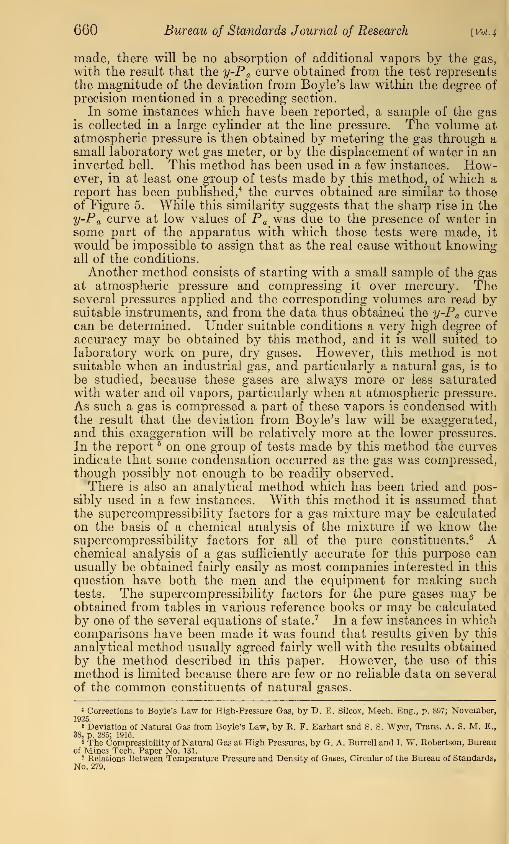
atmospheric pressure is then obtained by metering the gas through asmall laboratory wet gas meter, or by the displacement of water in aninverted bell. This method has been used in a few instances. How-ever, in at least one group of tests made by this method, of which areport has been published,4 the curves obtained are similar to thoseof Figure 5. While this similarity suggests that the sharp rise in they-Pa curve at low values of P a was due to the presence of water in
some part of the apparatus with which those tests were made, it
would be impossible to assign that as the real cause without knowingall of the conditions.
Another method consists of starting with a small sample of the gasat atmospheric pressure and compressing it over mercury. Theseveral pressures applied and the corresponding volumes are read bysuitable instruments, and from the data thus obtained the y-Pa curvecan be determined. Under suitable conditions a very high degree of
accuracy may be obtained by this method, and it is well suited to
laboratory work on pure, dry gases. However, this method is notsuitable when an industrial gas, and particularly a natural gas, is to
be studied, because these gases are always more or less saturatedwith water and oil vapors, particularly when at atmospheric pressure.
As such a gas is compressed a part of these vapors is condensed withthe result that the deviation from Boyle's law will be exaggerated,and this exaggeration will be relatively more at the lower pressures.
In the report 5 on one group of tests made by this method the curvesindicate that some condensation occurred as the gas was compressed,though possibly not enough to be readily observed.There is also an analytical method which has been tried and pos-
sibly used in a few instances. With this method it is assumed thatthe supercompressibility factors for a gas mixture may be calculated
on the basis of a chemical analysis of the mixture if we know thesupercompressibility factors for all of the pure constituents. 6 Achemical analysis of a gas sufficiently accurate for this purpose canusually be obtained fairly easily as most companies interested in this
question have both the men and the equipment for making suchtests. The supercompressibility factors for the pure gases may beobtained from tables in various reference books or may be calculated
by one of the several equations of state. 7 In a few instances in whichcomparisons have been made it was found that results given by this
analytical method usually agreed fairly well with the results obtainedby the method described in this paper. However, the use of this
method is limited because there are few or no reliable data on several
of the common constituents of natural gases.
4 Corrections to Boyle's Law for High-Pressure Gas, by D. E. Silcox, Mech. Eng., p. 897; November,1925.
4 Deviation of Natural Gas from Boyle's Law, by R. F. Earhart and S. S. Wyer, Trans. A. S. M. E.,
38, p. 285; 1916.6 The Compressibility of Natural Gas at High Pressures, by G. A. Burrell and I. W. Robertson, Bureau
of Mines Tech. Paper No. 131.7 Relations Between Temperature Pressure and Density of Gases, Circular of the Bureau of Standards,
No. 279.
Bean] Correction for Supercompressibility 661
6. ADDITIONAL NOTES ON THE OPERATION AND CONSTRUCTIONOF THE APPARATUS
Since the apparatus as described uses mercury, it is necessary thatthere be no parts or fittings, particularly in the mercury and gasleads, that the mercury will attack. This rules out brass fittings
and soldered joints for most parts, although pure copper tubing maybe used with but little danger of trouble. However, when the waterbath is used, it is desirable to avoid the use of iron and steel parts
unless they can be adequatefy protected against the action of waterand air.
For connecting the mercury reservoir with the manometer andburette, it is advisable to use a rubber tubing that will not foul themercury. Such tubing is obtainable under the name of " nitrometertubing."
"Whenever changing the pressure to which the tubing and trap are
subjected, care must be exercised to do it slowly, so as not to subjectthe glass portion of the trap to sudden pressure changes.The object of the glass portion of the trap is to enable one to see
that the surface of the trap fluid is always at the same height when-ever the pressure is determined. Exact readings or settings are notrequired, as a variation of one-twentieth of an inch either way fromthe line have onfy a very slight effect on the results. It is therefore
possible that in place of glass a tougher translucent material mightbe used (for example, so-called clear bakelite tubing). This wouldgreatly reduce the chance of breakage and trouble with the trap.
When charging cylinder A with a sample of gas it is advisable to
pass the gas first through some form of dust trap. This will preventdust particles from getting into the tubing and clogging the needlevalves. However, the gas should not be passed through a dryerunless a sample of dried gas is desired for some special reason.