1159| International Journal of Current Engineering and Technology, Vol.7, No.3 (June 2017)
An Artificial Neural Network Based Real-Time Optimal Reactive Power Flow for Improving Operation Efficiency Hasan I. Al-Rubaiey* and Rashid H. Al-Rubayi University of Technology/ Department of Electrical Engineering, Baghdad-Iraq
Accepted 12 June 2017, Available online 18 June 2017, Vol.7, No.3 (June 2017)
Abstract This paper presents a developed controller for a Static Var Compensator (SVC) System by using an Artificial Neural Networks (ANNs) for compensating unbalanced fluctuating loads and enhancing the efficiency of operating the distribution network namely; source power factor, load voltage profile, total line power losses, and line thermal limit factor. Two types of reactive power compensators are utilized, the Fixed Capacitor (FC), and the Thyristor- Controlled Reactor (TCR) type compensators. The proposed controller designed to reduce and balance the reactive power drifting from the supply bus-bar under many unbalanced load conditions while keeping the harmonic injection to the Point of Common Coupling (PCC) due to the SVC operation quietly low. The first stage of the proposed controller is Gravitational Search Algorithm (GSA). This algorithm determines the optimal thyristor firing angles of TCR that balance the system with a little drafting of the reactive power drawn from the supply and inject minimum harmonics to PCC indicated by Total Harmonic Distortion (THD). The computational speed of finding the optimum TCR's firing angles is improved by replacing the GSA by a set of online ANNs trained with hundreds of data generated from GSA. The proposed controller has been verified through proper simulation backed by practical Iraqi distribution network (Ghazali – Muhandessen 33 kV feeder). Finally, the study shows that the use of the ANNs is completely a suitable choice for the real-time control, load balancing, and reactive power compensation. Keywords: Static Var Compensator, Fixed Capacitor etc. Introduction
1 Reactive power has been perceived as a significant factor in the operation and design of electric power networks for a long time. In a very general and greatly simplified way it is recognized that the reactive power is produced and consumed throughout the network itself in significant quantities, which its amount depends on the system loading and network's configuration. Generators may have limited reactive power capability, sometimes their reactive power cannot be effectively used if the reactive power requirement in the electric network is far from their locations (Arshad Abduljabbar Najim, 2011). An increase in the consumption of reactive power causes lower values of power factor, which in turn increases the losses of the distribution system, voltage drop, instability of power system and power quality problems, like reducing the effective capacity of generating units and system components. On the other hand, most of alternating current power systems are three phases, and they are designed for balanced operation condition, any unbalanced operation like unbalanced consumption of reactive power in a wide *Corresponding author: Hasan I. Al-Rubaiey
range within short time, gives rise to unwanted components of currents in the wrong phase sequence (undesired negative and zero sequence currents). The power distribution systems are facing a variety of issues due to proliferation the application of non- linear loads. In addition to poor power factor correction, voltage profile, harmonic injection, and unbalanced load compensation are become the major concerns for the utility system (Sankar Das et al, 2015). Thus, it is necessary to control the reactive power, so that the alternating current electric power system works as close as possible to the ideal power system (balanced system). Partial or complete reactive power compensation is continuously gaining an increasing interest since the generation, transmission and consumption networks are becoming bigger and more complicated day after day (Timothy J. E. Miller, 2015). Among the Flexible Alternating Current Transmission System (FACTS) controllers, the (SVC) Static VAR Compensator have been explored and deployed to reactive power compensation so as to achieve the power factor correction & load balancing. SVC controller type FC-TCR is taken up for study in this paper, which is the variable impedance device that is connected in shunt way with the electric power system
Hasan I. Al-Rubaiey et al An Artificial Neural Network Based Real-Time Optimal Reactive Power Flow for Improving Operation Efficiency
1160| International Journal of Current Engineering and Technology, Vol.7, No.3 (June 2017)
and can continuously and rapidly generate or absorb the required reactive power for load compensating. The basic elements of Thyristor Controlled Reactor (TCR) are antiparallel thyristors connected in series with a reactor as shown in Fig. 1 (Arshad Abduljabbar Najim, 2011).
Fig. 1 Basic Elements of Thyristor Controlled Reactor (TCR)
However, the operation of SVC at appropriate thyristors's firing angles can be used profitably to meet the varying and phase-wise unbalanced load reactive power demand in the network, such an operation can pollute the power supply in another form by introducing harmonics currents into the supply source, so it becomes necessary either to minimize/eliminate the generating of harmonics internally in SVC or using a harmonics external filters but with additional costs & space. Part of this paper deals with minimizing the harmonics generation in SVC and to achieve load balancing internally by using optimized thyristors's firing angles determent by artificial intelligence optimization techniques (Deepak Balkrishna Kulkarni et al, 2010). Several papers have covered different controlling methods for SVC to compensate the reactive power in electric distribution networks. To keep the harmonic injection to the PCC due to operation of SVC low while balancing the source reactive power, Genetic algorithm (GA) based ANN training was used to figure out the firing angles of TSC-TCR thyristors in order to get optimum operation in (D. B. Kulkarni et al., 2009). In (V. Lakshmi Devi et al., 2011) a static VAR compensator (SVC) type (TSC-TCR) is applied to the 11kV/400V distribution transformer, a new approach with ANN and Fuzzy logic system in order to get the optimum combinations of firing delay angles that meet minimum THD with acceptable compromised (Qs) reactive power drawn from the Source. A modified artificial intelligent (AI) technique and SVC combination with passive filter to minimize the harmonics are used in (Mr. Sanjy Prajapati et al., 2015). Changing in the topology of FC-TCR in order to get lower THD is studied in (Mohammad Hasanuzzaman Shawon, et al. 2015). The PI controller with Fuzzy logic system in (V. Suma Deepthi et al., 2016) are used to obtain optimum triggering delay angle of TCR [0 – 90] degree. During this paper an algorithm for online control of FC-TCR type of SVC is developed such that the SVC Improve the source power factor by minimizing the
balanced reactive power (QS) drawn from the supply, balancing the reactive power drawn from the supply, Minimizing the total current supplied by the source which leads to reduce the total power losses in the line, Eliminate the negative sequence current generated by unbalance loads, Improvement in load voltage profile, and Enhancing in Thermal Limit Factor TLF of the lines. The resulting controller uses Gravitational Search Algorithm (GSA) and ANN to determine the optimum firing delay angles. System Modelling A. Compensation requirement for load balancing The proposed FC-TCR type of SVC with the typical power system is considered for the analysis in this paper. The model used to present the typical load requiring compensation is shown in Fig. 2, where the FC and TCR are connected in star ϒ and delta ∆, respectively.
Fig.2 Representation of Distribution Substation with FC-TCR type SVC
The FC-TCR compensator basically functions as a variable reactance (inductive and capacitive impedances) by controlling the TCR firing angle. A series of such unbalanced steady state loads at different time instances are used in order to establish the basic compensation requirements in load balancing. With this assumption, the compensator requirement is to absorb/generate an unbalance reactive power between the supply system and load demand, when it is combined with the load, will represent balanced reactive power to the supply system. Consider a system as shown in Fig. 2, where bus bar (1) represents the AC source system node and bus bar (2) represents the load bus, with static VAR compensator (FC-TCR) type connected at that bus. Let PLa + jQLa, PLb + jQLb and PLc + jQLc be the phase-wise loads demand at a given time instant. After the compensation, let the phase-wise loads seen by the source (bus bar 1) to be PLa + jQSa, PLb + jQSb and PLc + jQSc respectively. The complex phase-wise voltages at the load bus (bus bar 2) after the compensation are given by:
Hasan I. Al-Rubaiey et al An Artificial Neural Network Based Real-Time Optimal Reactive Power Flow for Improving Operation Efficiency
1161| International Journal of Current Engineering and Technology, Vol.7, No.3 (June 2017)
(A.1) Where VL = [VLa, VLb, VLc] T is the complex voltage vector at the load bus (2), VS= [VSa, VSb, VSc] T is the complex voltage vector at the source bus (1), and Z = diagonal [Za, Zb, Zc] T is the line impedance matrix between the buses. The line currents between the load bus and source bus after the compensation I = [Ia, Ib, Ic] T are obtained from (V. Suma Deepthi et al., 2016):
⁄ (A.2a)
⁄ (A.2b)
⁄ (A.2c) The non-linear set of the complex equations (A.1) and (A.2a,b,c) can be solved for load bus voltages using Forward- Backward Sweep (FBS) load flow method. The equation which is required for balanced system to meet unbalanced operation is:
(A.3)
Where QL = [QLa, QLb, QLc] T is the phase-wise vector of load reactive power demand, QC = [QCa, QCb, QCc] T is the phase-wise vector of reactive power supplied by FC, QS = [QSa, QSb, QSc] T is the phase-wise vector of reactive power supplied from the source bus and QR = [QRa, QRb, QRc] T is the phase-wise vector of reactive power absorbed by TCR. In the case of load balancing application, we want to make the reactive powers per phase supplied by the source (bus 1) balanced and equal, that is QSa = QSb = QSc = QS. Further, we want to have the value of QS as close as possible to zero, we also have QCa = QCb = QCc = QC reactive power supplied by the fixed capacitor. After setting the values of QS and QC the unbalanced reactive power [QR]abc absorbed by the TCR can be obtained by solving equation (A.3) (Sankar Das et al 2015). The values of Xab, Xbc, Xca (delta connected TCR
compensator reactances) required to absorb the
unbalanced reactive power computed from (A.3) can
be obtained from the below equations, these equations
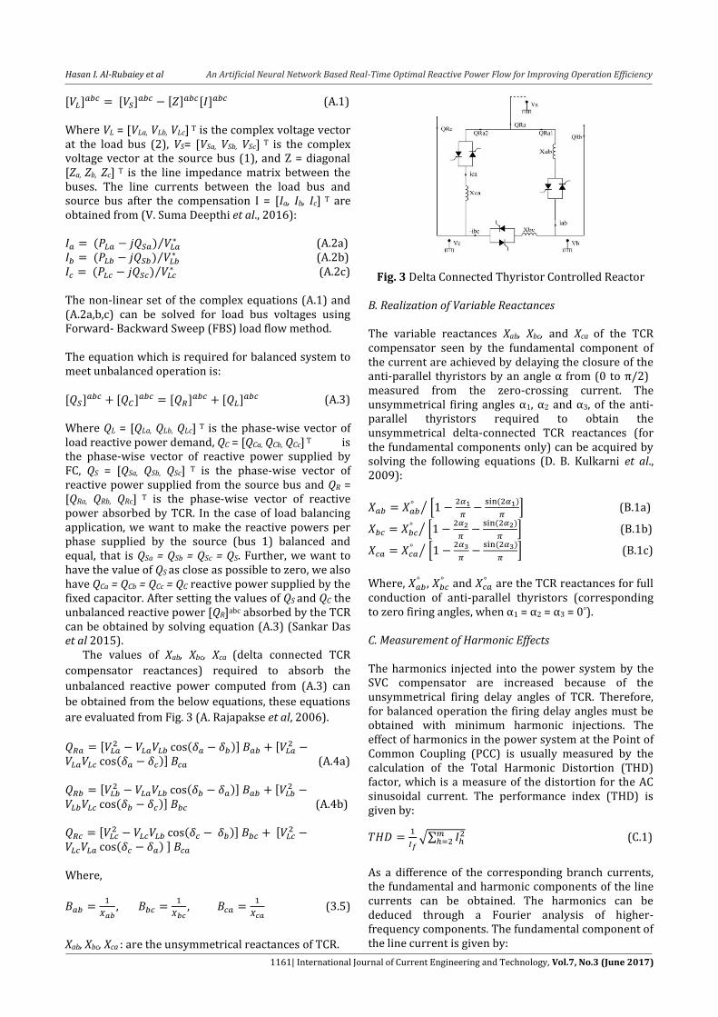
are evaluated from Fig. 3 (A. Rajapakse et al, 2006).
(A.4a)
(A.4b)
Where,
(3.5)
Xab, Xbc, Xca : are the unsymmetrical reactances of TCR.
Fig. 3 Delta Connected Thyristor Controlled Reactor B. Realization of Variable Reactances The variable reactances Xab, Xbc, and Xca of the TCR compensator seen by the fundamental component of the current are achieved by delaying the closure of the anti-parallel thyristors by an angle α from (0 to π/2)
measured from the zero-crossing current. The unsymmetrical firing angles α1, α2 and α3, of the anti-parallel thyristors required to obtain the unsymmetrical delta-connected TCR reactances (for the fundamental components only) can be acquired by solving the following equations (D. B. Kulkarni et al., 2009):
[
]⁄ (B.1a)
[
]⁄ (B.1b)
[
]⁄ (B.1c)
Where,
, and
are the TCR reactances for full conduction of anti-parallel thyristors (corresponding to zero firing angles, when α1 = α2 = α3 = 0°). C. Measurement of Harmonic Effects The harmonics injected into the power system by the SVC compensator are increased because of the unsymmetrical firing delay angles of TCR. Therefore, for balanced operation the firing delay angles must be obtained with minimum harmonic injections. The effect of harmonics in the power system at the Point of Common Coupling (PCC) is usually measured by the calculation of the Total Harmonic Distortion (THD) factor, which is a measure of the distortion for the AC sinusoidal current. The performance index (THD) is given by:
√∑
(C.1)
As a difference of the corresponding branch currents, the fundamental and harmonic components of the line currents can be obtained. The harmonics can be deduced through a Fourier analysis of higher-frequency components. The fundamental component of the line current is given by:
Hasan I. Al-Rubaiey et al An Artificial Neural Network Based Real-Time Optimal Reactive Power Flow for Improving Operation Efficiency
1162| International Journal of Current Engineering and Technology, Vol.7, No.3 (June 2017)
√
(C.2)
Where, (C.3)
√ (C.4)
The harmonic components of the line current for hth order harmonic is given by:
√
(C.5)
Where,
(C.6)
√
(C.7)
The phase difference between (fundamental, harmonic)’s voltage and current respectively is given by: ⁄ (C.8)
⁄ (C.9) Where,
h = harmonic order , k = 1, 2, 3, …..,
(+Ve) sign is for harmonic of order .
(-Ve) sign is for harmonic of order .
Each and for phase A, each and
for phase B, and each and for
phase C. The is the phase difference between line
voltages.
For three-phase systems, the preferred arrangement of
TCR is in delta connection, because when the system is
balanced, all the triplen harmonics (multiples of third)
circulated in the closed delta connection path are
absent from the line currents as follows:
For triple harmonics (3rd, 9th, …..):
(C.10)
Equations (C.1) to (C.10) were used in the optimization
program to perform simulation. This is to obtain
optimum firing angles corresponding to minimum
harmonics (V. Suma Deepthi et al., 2016).
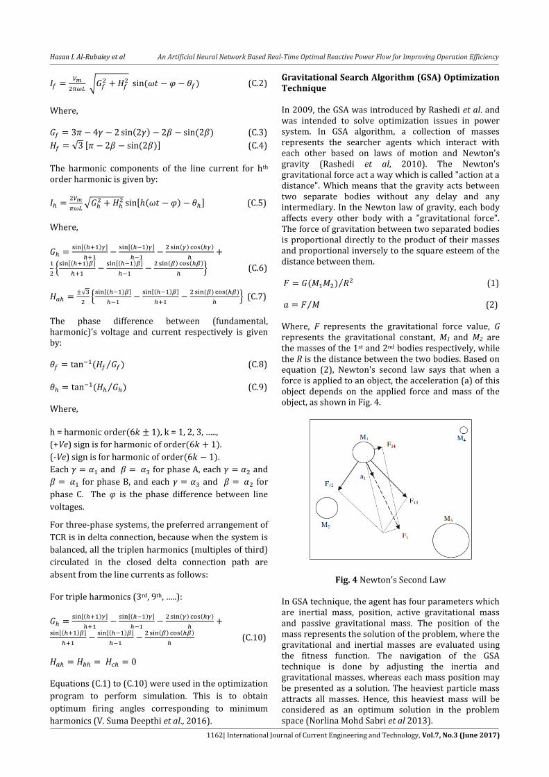
Gravitational Search Algorithm (GSA) Optimization Technique In 2009, the GSA was introduced by Rashedi et al. and was intended to solve optimization issues in power system. In GSA algorithm, a collection of masses represents the searcher agents which interact with each other based on laws of motion and Newton's gravity (Rashedi et al, 2010). The Newton's gravitational force act a way which is called "action at a distance". Which means that the gravity acts between two separate bodies without any delay and any intermediary. In the Newton law of gravity, each body affects every other body with a "gravitational force". The force of gravitation between two separated bodies is proportional directly to the product of their masses and proportional inversely to the square esteem of the distance between them. ⁄ (1) ⁄ (2) Where, F represents the gravitational force value, G represents the gravitational constant, M1 and M2 are the masses of the 1st and 2nd bodies respectively, while the R is the distance between the two bodies. Based on equation (2), Newton's second law says that when a force is applied to an object, the acceleration (a) of this object depends on the applied force and mass of the object, as shown in Fig. 4.
Fig. 4 Newton's Second Law In GSA technique, the agent has four parameters which are inertial mass, position, active gravitational mass and passive gravitational mass. The position of the mass represents the solution of the problem, where the gravitational and inertial masses are evaluated using the fitness function. The navigation of the GSA technique is done by adjusting the inertia and gravitational masses, whereas each mass position may be presented as a solution. The heaviest particle mass attracts all masses. Hence, this heaviest mass will be considered as an optimum solution in the problem space (Norlina Mohd Sabri et al 2013).
Hasan I. Al-Rubaiey et al An Artificial Neural Network Based Real-Time Optimal Reactive Power Flow for Improving Operation Efficiency
1163| International Journal of Current Engineering and Technology, Vol.7, No.3 (June 2017)
Proposed GSA Based Harmonic Minimization For a given reactive power load demand QL it is necessary to reduce the reactive power drawn from the supply QS. By setting balance values for QS and QC, the unbalanced reactive power [Q R]abc absorptions by TCR can be obtained using the procedure in section A. Now the unsymmetrical reactances Xab, Xbc, and Xca required to absorbing [QR]abc and the corresponding unsymmetrical firing delay angles of the TCR can be computed from section B. Knowing the firing angles and the voltages at the SVC node, harmonic analysis can be evaluated and the performance index THD can be carried out as explained in section C. Because of the different combinations of firing angles α1, α2 and α3 lead to various harmonic levels magnitude, as indicated by the THD the performance index. In order to reduce the harmonics generated from the compensator operation, the TCR compensator should be working at a compensation of firing angles that produce low harmonic levels to the system. It has been further clear that there are many combinations of firing delay angles which lead to depress the level of harmonic generation. The combination of firing delay angles of TCR that corresponds to the minimum THD magnitude usually struggle with the objective of minimizing the QS (reactive power drawn from the supply). Therefore, it is important to find a combination of firing delay angles, which can simultaneously keep both the THD and QS satisfactory low (D. B. Kulkarni et al., 2009). However, the task of choosing the particular combination of TCR firing delay angles from a set of all feasible combinations of firing delay angles to accomplish optimum values of THD and QS is done by using GSA optimization technique because the load is continuously changing with the time and SVC controller designed to be capable of choosing the appropriate set of firing delay angles without human intervention. The firing delay angles correspond to minimum THDavg. values and an acceptable compromised Qs value in terms of power factor is formulated in this current work by the objective function with the GSA as follows: ⁄ (3)
Where, represents the average value of
performance index THD of all the three phases, represents the maximum value amongst all the three phases THD, and represents the
average power factor amongst the three phases of the system. In terms of α1, α2 and α3 the objective function is calculated for a load sample. The boundaries of the reactive power drawn from the supply QS used in optimization issues are: , (4)
Where, represents the average active power
amongst all the three phases of the system.
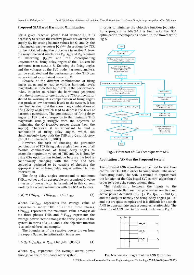
In order to minimize the objective function (equation 3), a program in MATLAB is built with the GSA optimization techniques as shown in the flowchart of Fig. 5.
Fig. 5 Flowchart of GSA Technique with SVC
Application of ANN on the Proposed System The proposed ANN algorithm can be used for real time control for FC-TCR in order to compensate unbalanced fluctuating loads. The ANN is trained to approximate the function of the GSA based SVC control algorithm in order to reduce the computational time. The relationship between the inputs to the proposed controller, such as phase-wise reactive and active power demands (PLa, QLa, PLb, QLb, PLc and QLc) and the outputs namely the firing delay angles (α1, α2 and α3) are quite complex and it is difficult for a single ANN to approximate such a complex relationship. The structure of ANN used in this work is shown in Fig. 6.
Fig. 6 Schematic Diagram of the ANN Controller
Hasan I. Al-Rubaiey et al An Artificial Neural Network Based Real-Time Optimal Reactive Power Flow for Improving Operation Efficiency
1164| International Journal of Current Engineering and Technology, Vol.7, No.3 (June 2017)
In order to reduce the complexity of the proposed ANN only the reactive power demands (QLa, QLb and QLc) were used as inputs to the controller because the dependency of the outputs on active power demand is only minimal. Since the training of multi-output ANN is hard to achieve, a system of single-output ANN is used to realize the SVC controller. The ANNs are trained using the data generated from GSA based controller with load profiles pf the proposed case study. These load profiles cover all expected regions of operations. Fig. 7 shows the flowchart of the proposed back propagation algorithm of feed forward neural network used in this paper.
Fig.7 Flowchart for Back-Propagation Training of Feed- Forward Neural Network
Case Study and Simulation Results
A. Al-Gazali – Muhandseen 33 kV Feeder Case Study from Iraqi Distribution Network This paper takes into account the summer, winter, spring, and autumn seasons in Iraq during 2016, Fig. 8 shows 900 samples of unbalanced reactive power load profile of this substation, these data have been collected from Al-Muhandseen substation's SIEMENS board as shown in Fig. 9. Rusafa - Baghdad 33 kV distribution network. Al-Muhandseen substation is supplied by two main feeders from Al-Gazali substation with length of 2.593 km. Al-Gazali substation is equipped with two power transformers of 132/33 kV, every single transformer of power rating 50 MVA, and five 33 kV feeders are outgoing from each. Al-Muhandseen substation contains two distribution transformers of 33/11 kV with power rating of 31.5 MVA. Seven 11 kV feeders of
each transformer outgoing from Al-Muhandseen substation serving a large area of mixed residential and commercial loads.
Fig.8 900 Samples of Reactive Power Profile of Al-Muhandseen Distribution Substation during 2016
Fig.9 Al-Muhandseen Substation's SIEMENS Board
The studied case is selected as a part of center of Al- Only one feeder of 33 kV outgoing from transformer no. 1 of Al-Gazali substation is considered in this work. The impedance of the considered feeder between the supply side (Al-Gazali TR-1) and the load side (Al-Muhandseen TR-1) is taken as Z = 0.13613 + j0.2593 Ω for each phase. A 1-core, 1*400 mm 33 kV under-ground cable with XLPE insulation is used in Gazali – Muhandseen feeder for each phase. The underground capacitors are neglected. The actual distribution network of Al-Muhandseen substation TR-1 feeders from satellite are shown in Fig. 10.
B. The Intelligent Algorithm Results Gravitational Search Algorithm (GSA) technique as explained before is used in this paper in order to select the optimum firing angles of TCR from many applicable firing angles, the chosen firing angles should meet the minimum harmonic injection to the power system with acceptable value of reactive power drawn from the
Hasan I. Al-Rubaiey et al An Artificial Neural Network Based Real-Time Optimal Reactive Power Flow for Improving Operation Efficiency
1165| International Journal of Current Engineering and Technology, Vol.7, No.3 (June 2017)
supply (Eq. 3) and it should satisfy the balance operation condition (Eq. A.3). Table (1) shows the optimum firing delay angles of the TCR, Optimized average source power factor, and average THD by using the intelligent technique
procedure as mentioned in Flowchart of Fig. 5 for GSA for part of load samples mentioned in Fig. 8 (45 samples taken randomly because we cannot present all the 900 samples, not enough space).
Fig. 10 Satellite Picture of Al-Muhandseen 33/11 kV Distribution Network of TR-1
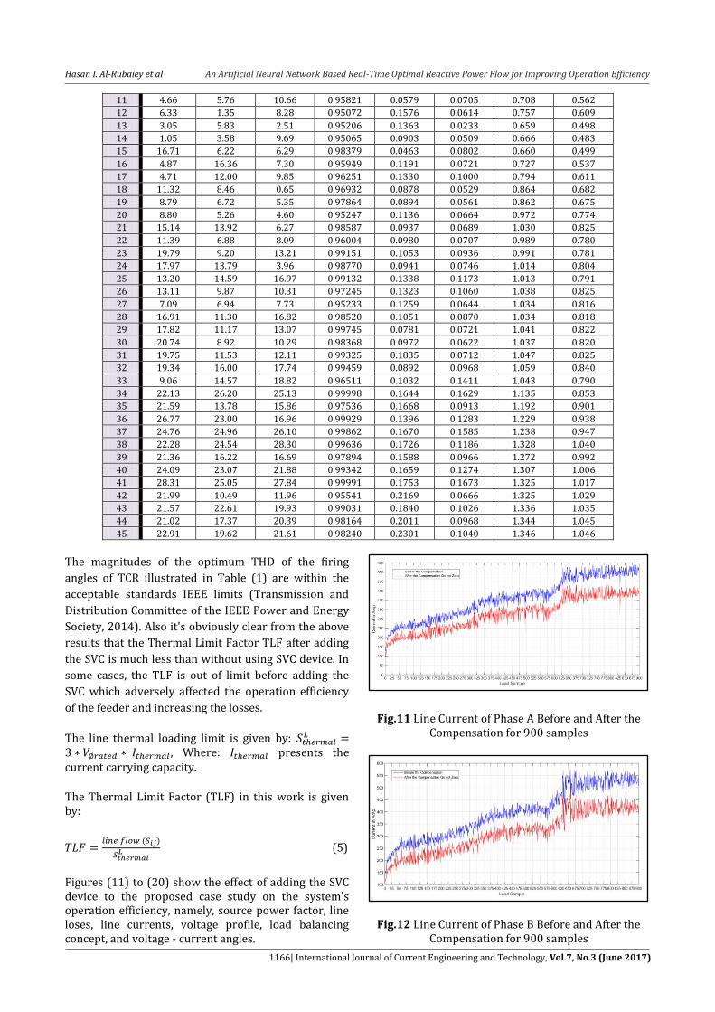
Table 1 Optimum Firing Angles and THD Using GSA Technique for 45 Samples Load Profile
angles of TCR illustrated in Table (1) are within the
acceptable standards IEEE limits (Transmission and
Distribution Committee of the IEEE Power and Energy
Society, 2014). Also it's obviously clear from the above
results that the Thermal Limit Factor TLF after adding
the SVC is much less than without using SVC device. In
some cases, the TLF is out of limit before adding the
SVC which adversely affected the operation efficiency
of the feeder and increasing the losses.
The line thermal loading limit is given by:
, Where: presents the current carrying capacity.
The Thermal Limit Factor (TLF) in this work is given by:
(5)
Figures (11) to (20) show the effect of adding the SVC device to the proposed case study on the system's operation efficiency, namely, source power factor, line loses, line currents, voltage profile, load balancing concept, and voltage - current angles.
Fig.11 Line Current of Phase A Before and After the
Compensation for 900 samples
Fig.12 Line Current of Phase B Before and After the Compensation for 900 samples
Hasan I. Al-Rubaiey et al An Artificial Neural Network Based Real-Time Optimal Reactive Power Flow for Improving Operation Efficiency
1167| International Journal of Current Engineering and Technology, Vol.7, No.3 (June 2017)
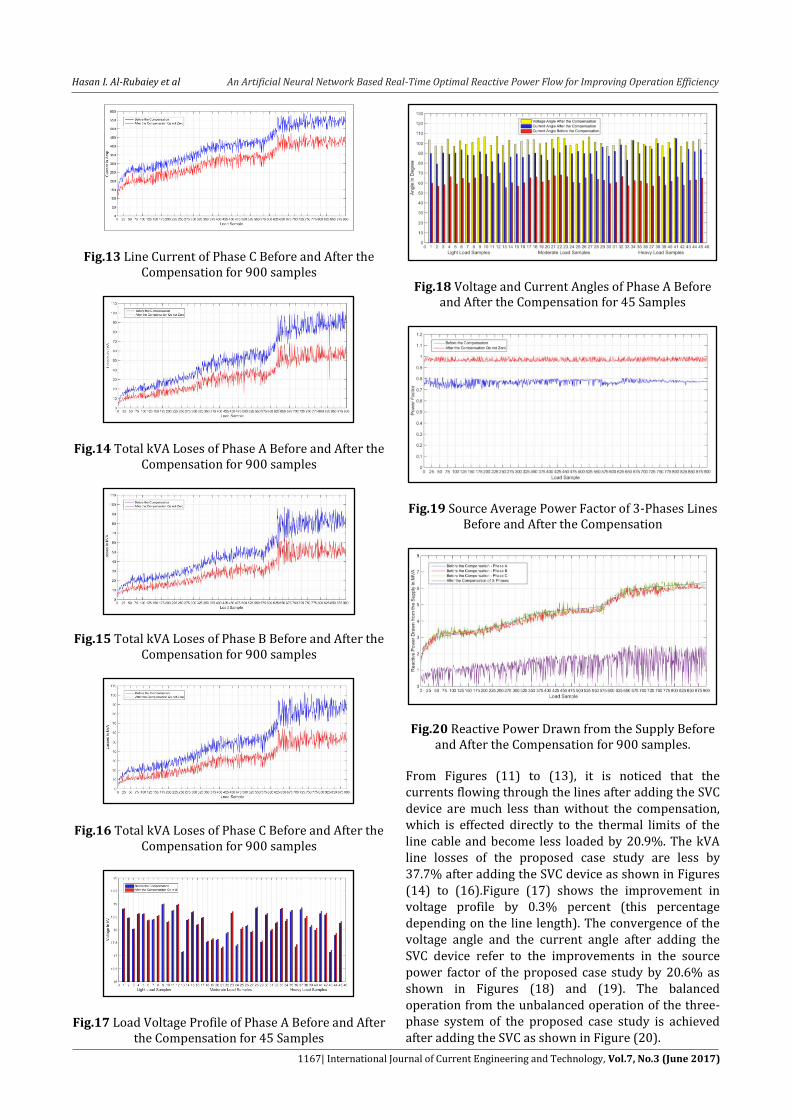
Fig.13 Line Current of Phase C Before and After the Compensation for 900 samples
Fig.14 Total kVA Loses of Phase A Before and After the Compensation for 900 samples
Fig.15 Total kVA Loses of Phase B Before and After the Compensation for 900 samples
Fig.16 Total kVA Loses of Phase C Before and After the Compensation for 900 samples
Fig.17 Load Voltage Profile of Phase A Before and After the Compensation for 45 Samples
Fig.18 Voltage and Current Angles of Phase A Before and After the Compensation for 45 Samples
Fig.19 Source Average Power Factor of 3-Phases Lines Before and After the Compensation
Fig.20 Reactive Power Drawn from the Supply Before and After the Compensation for 900 samples.
From Figures (11) to (13), it is noticed that the currents flowing through the lines after adding the SVC device are much less than without the compensation, which is effected directly to the thermal limits of the line cable and become less loaded by 20.9%. The kVA line losses of the proposed case study are less by 37.7% after adding the SVC device as shown in Figures (14) to (16).Figure (17) shows the improvement in voltage profile by 0.3% percent (this percentage depending on the line length). The convergence of the voltage angle and the current angle after adding the SVC device refer to the improvements in the source power factor of the proposed case study by 20.6% as shown in Figures (18) and (19). The balanced operation from the unbalanced operation of the three-phase system of the proposed case study is achieved after adding the SVC as shown in Figure (20).
Hasan I. Al-Rubaiey et al An Artificial Neural Network Based Real-Time Optimal Reactive Power Flow for Improving Operation Efficiency
1168| International Journal of Current Engineering and Technology, Vol.7, No.3 (June 2017)
C. SVC Based ANNs Results In this section, SVC that is based on ANNs controller is employed to the proposed case study system in order to reduce the computational time of finding the optimum firing angles. The neural control system has three inputs which are the 3-phase load reactive power (Fig. 8). The output of ANNs is the optimal firing angles that are calculated from GSA algorithm, Fig. (5). By applying the procedure of Flowchart in Fig. (7) a Simulink model of ANN has been implemented as shown in Fig. 21. The ANNs have been trained by using 900 training data for each phase (Fig. 8) that collected from Al-Muhandseen substation.
Fig. 21 The ANNs Simulation Fig. 22 shows the computational time of finding the optimum firing angles between GSA algorithm and ANNs controller.
Fig. 22 Time Comparison of Obtaining Firing Angles
From the above results, it's clear that the time of finding the optimum firing delay angles of TCR by using ANNs is much less than by using GSA algorithm, which proved the ANN is suitable choice for on-line load balancing purposes. Should mention the ANN have been trained with 900 unbalance case for each phase and covered all the possible load demand during the year which made it more efficient and reliable.
Conclusion The aim of this research was to develop a controller with a multiple objectives for static var compensator compensating unbalanced loads which is 1) balancing the reactive power Qs drifting from the source 2) minimizing the reactive power Qs drifting from the source 3) decreasing the harmonic injection to the PCC due to SVC operation and 4) improving the efficiency of operating the distribution network. The main concluding that can be extracted from this work can be summarized as follows: 1) FC-TCR type of SVC can be used for fluctuating
loads due to low losses, low cost and moderately complex control strategy.
2) There are many combinations of thyristor firing angles that can balance the power system, but each combination injects different rate of harmonics to the system.
3) TCR firing angles directly affect the harmonic magnitudes of the AC line current.
4) The intelligent algorithm techniques are more efficient and accurate than the conventional algorithm in finding the optimal firing delay angles of TCR.
5) The GSA technique during this study is chosen to be the ideal solution for finding the optimum combination of firing angels. The total harmonic distortion factor of the optimized firing angles by GSA is much less than the un-optimized one (Qs = 0) by 33%.
6) The results from the intelligent technique show that, the SVC device has a significant effect in improving the operation efficiency of the proposed system as summarized in Table below:
Table 2 Enhancement Rate of Operation Efficiency
Operating Factors
Gazali – Muhandseen Feeder
Samadiya – Mazara'a Feeder
Enhancing Rate Enhancing Rate
Source P.F. 20.6% 19.03%
Line Current Reduction in load on
feeder by 20.9%
Reduction in load on feeder by by
22.4% Voltage Profile 0.3% 22.3%
MVA Losses Reduction in line losses by 37.7%
Reduction in line losses by 39.7%
TLF Losses in form of
heat are reduced by 22.1%
Losses in form of heat are reduced by
22.1% Qs Balancing 100% 100%
ANN is proved to be a suitable choice for online
purposes because it provides firing delay angles much faster than the intelligent algorithm (GSA) by 98%.
The proposed algorithm of this study is suitable for different feeder lengths and it is an elastic
Hasan I. Al-Rubaiey et al An Artificial Neural Network Based Real-Time Optimal Reactive Power Flow for Improving Operation Efficiency
1169| International Journal of Current Engineering and Technology, Vol.7, No.3 (June 2017)
algorithm which can be accommodated for feeder needs.
References Arshad Abduljabbar Najim (2011), Static VAR Compensator
(SVC) Modeling for the Iraqi National Super High Voltage Grid System, M.Sc. thesis, University of Baghdad.
Sankar Das, Debashis Chatterjee, Swpan K. Goswami (2015), A GSA Based Modified SVC Switching Scheme for Load Balancing and Source Power Factor Improvement, IEEE Transactions on Power Delivery.
Timothy J. E. Miller (2015), Reactive Power Control in Electric Systems, A Wiley Interscience Publication, John Wiley & Sons.
Deepak Balkrishna Kulkarni, G. R. Udupi (July 2010), ANN-Based SVC Switching at Distribution Level for Minimal-Injected Harmonics, IEEE Transactions on Power Delivery, Vol. 25, NO. 3.
D. B. Kulkarni, G. R. Udupi (2009), Optimum Switching of TSC TCR Using GA Trained ANN for Minimum Harmonic Injection, IEEE Second International Conference on Emerging Trends in Engineering and Technology, ICETET-09.
V. Lakshmi Devi, T. Phanindra (2011), Novel Approach for Minimal Injected Harmonics at Distribution Level - SVC, International Journal of Smart Sensors and Ad Hoc Networks (IJSSAN), Volume -1, Issue-1.
Sanjay Prajapati, Mr. Vishal Gandhi, Mr. Rishikesh Agrawal, Mitul Vekaria (2015), Mitigating the Harmonic Distortion in Power System Using SVC With AI Technique, International journal for Scientific Research & Development, Vol. 3, Issue 03.
Mohammad Hasanuzzaman Shawon, Zbigniew Hanzelka, Aleksander Dziadecki (July 2015), Voltage-Current and Harmonic Characteristic Analysis of Different FC-TCR Based SVC, IEEE, University of Science & Technology, Krakow, Poland.
V. Suma DeepthiP, P. Sankar Babu (January 2016), Implementation of Fuzzy Logic Approach on TSC-TCR SVC Switching At Distribution Level for Minimal Injected Harmonics, International Journal of Scientific Engineering and Applied Science (IJSEAS), Volume-2, Issue-1.
A. Rajapakse, Anawat Puangpairoj (2006), Harmonic Reducing ANN Controller for a SVC Compensating Unbalanced Fluctuating Loads, International Journal of Emerging Electric Power Systems, Vol. 7, Issue 1, Article 5.
Rashedi, E., Nezamabadi-pour, H. & Saryazdi (2010), BGSA: Binary Gravitational Search Algorithm, Natural Computing, Springer 9 (No. 3): 727-745.
Norlina Mohd Sabri, et al. (November 2013), A Review of Gravitational Search Algorithm, Int. J. Advance. Soft Comput. Appl., Vol. 5, No. 3.
Transmission and Distribution Committee of the IEEE Power and Energy Society (2014), IEEE Recommended Practice and Requirements for Harmonic Control in Electric Power Systems, IEEE Std. 519™ -2014 (Revision of IEEE Std 519-1992).