An E CLIPSE Framework for Rapid Development of Rich-featured GEF Editors based on EMF Models - Long Version - Tony Modica, Enrico Biermann, Claudia Ermel Institut f ¨ ur Softwaretechnik und Theoretische Informatik Technische Universit¨ at Berlin E-Mail: {modica,enrico,lieske}@cs.tu-berlin.de Abstract: Model-based development has an increasing importance in modern soft- ware engineering and other domains. Visual models such as Petri nets and UML diagrams proved to be an adequate way to illustrate many structural and behavioral system properties. However, while tooling for textual modeling is pretty mature now, visual tool builders are faced with a much higher complexity regarding the represen- tation of model properties, and the interplay of the concrete syntax (the views) with the underlying abstract model representation, e.g. based on Java, XML or the Eclipse Modeling Framework (EMF). In order to ease the development of visual editors, the Graphical Editing Framework (GEF) offers layout and rendering possibilities, as well as an architecture that allows to integrate models based on EMF, Java or XMI with their visual views and editors. Unfortunately, the structure of GEF is quite complex to use if editors are not simply one-to-one representations of model elements, or if more than one view is needed at a time for more complex models. Based on several years of experience in teaching the development of GEF-based visual editors for complex visual models to students, we developed MUVITORKIT (Multi-View Editor Kit), a framework for rich-featured visual editors, which is pre- sented in this paper. MUVITORKIT is based on EMF and GEF, and supports nested models, models needing multiple graphical viewers, and animated simulation of model behavior. The architecture of MUVITORKIT is designed in a way that encapsulates the complex underlying mechanisms in GEF and simplifies the integration in the ECLIPSE workbench. 1 Introduction Model-based development grows more and more important in modern software engineer- ing. For a long time, visual models were restricted to pencil drawings on paper, used in the early software development phases to illustrate structural and behavioral system as- pects. While textual modeling had been supported by tools pretty early, visual modeling tools have been developed much later. Tool builders of visual modeling tools still face a number of problems such as layouting, pretty-drawing, view management and version control. The ECLIPSE Graphical Editing Framework (GEF) allows editor developers to implement graphical editors for existing models. GEF provides the layout and rendering toolkit DRAW2D for graphics and follows the model-view-controller (MVC) architectural
Transcript
An ECLIPSE Framework for Rapid Development ofRich-featured GEF Editors based on EMF Models
- Long Version -
Tony Modica, Enrico Biermann, Claudia ErmelInstitut fur Softwaretechnik und Theoretische Informatik
Abstract: Model-based development has an increasing importance in modern soft-ware engineering and other domains. Visual models such as Petri nets and UMLdiagrams proved to be an adequate way to illustrate many structural and behavioralsystem properties. However, while tooling for textual modeling is pretty mature now,visual tool builders are faced with a much higher complexity regarding the represen-tation of model properties, and the interplay of the concrete syntax (the views) withthe underlying abstract model representation, e.g. based on Java, XML or the EclipseModeling Framework (EMF). In order to ease the development of visual editors, theGraphical Editing Framework (GEF) offers layout and rendering possibilities, as wellas an architecture that allows to integrate models based on EMF, Java or XMI withtheir visual views and editors. Unfortunately, the structure of GEF is quite complex touse if editors are not simply one-to-one representations of model elements, or if morethan one view is needed at a time for more complex models.
Based on several years of experience in teaching the development of GEF-basedvisual editors for complex visual models to students, we developed MUVITORKIT(Multi-View Editor Kit), a framework for rich-featured visual editors, which is pre-sented in this paper. MUVITORKIT is based on EMF and GEF, and supports nestedmodels, models needing multiple graphical viewers, and animated simulation of modelbehavior. The architecture of MUVITORKIT is designed in a way that encapsulates thecomplex underlying mechanisms in GEF and simplifies the integration in the ECLIPSEworkbench.
1 Introduction
Model-based development grows more and more important in modern software engineer-ing. For a long time, visual models were restricted to pencil drawings on paper, used inthe early software development phases to illustrate structural and behavioral system as-pects. While textual modeling had been supported by tools pretty early, visual modelingtools have been developed much later. Tool builders of visual modeling tools still facea number of problems such as layouting, pretty-drawing, view management and versioncontrol. The ECLIPSE Graphical Editing Framework (GEF) allows editor developers toimplement graphical editors for existing models. GEF provides the layout and renderingtoolkit DRAW2D for graphics and follows the model-view-controller (MVC) architectural
pattern to synchronize model changes with its views and vice versa.
Our research group has its main focus on applying formal techniques to visual modelinglanguages. For five years now, we have held a visual languages programming project(VILA) for graduate students, concerning the development of a graphical editor as anECLIPSE plug-in, using GEF and the Eclipse Modeling Framework (EMF).
Generally, with a complex framework as GEF there are always many different possibil-ities to approach the implementation of a feature, but usually there are better and worseways, especially if you want to reuse code later on. Several frameworks support genera-tion of code for from abstract editor specifications, like the ECLIPSE Graphical ModelingFramework (GMF) or MOFLON [AKRS06]. Unfortunately, the visual languages we usu-ally want to implement editors for and their simulation operations seem not appropriate tobe specified in these frameworks, which assume models to be displayed in a single paneonly. Moreover, if we used e.g. GMF to generate code as far as possible, GEF apprenticeswithout deeper knowledge of the mechanisms in GEF would surely struggle when layinghand on the generated code to extend it with complex features.
Some experiences we made Every year, we choose a specific visual language of ourcurrent research, i.e in the first two years a new visual notation for OCL constraints andlater more complex models that integrate approaches for different aspects of a system, e.g.class diagrams and typed graphs (structure), Petri nets and activity diagrams (behavior),and graph or Petri net transformation rules (behavior and reconfiguration).
In the first phase of each project, we had to deal with the steep learning curve of GEF andECLIPSE programming. We did not want to spend much time on occupying the studentswith analyzing solely the example editors shipped with GEF and producing simple editorsthat they could not use directly for the project’s goal, because the example editors did notuse generated EMF models. Besides, in the early years of GEF, the only available docu-mentation was the IBM RedBook [MDG+04] (recently, a growing number of introductorytutorials and overviews have been made freely accessible). We let the students adapt asimple editor for a similar model, e.g. a graph editor to a Petri net editor, or vice versa,to get an impression of the main principles while modifying the existing code to work onanother newly generated EMF model. Unfortunately, we noticed that many students werediscouraged by the complexity of the code or/and were not able to distinguish code forthe editor functionalities from code that is simply needed to integrate the editor into theECLIPSE workbench. Moreover, with the more complex models, requirements arose thatcould not be fulfilled by GEF’s default editor implementation, which has just one panel tooperate on, showing just one graphical viewer at a time.
Another problem stemmed from the project scheduling, which stipulates starting witheasy-to-build components. For example, we cannot simply start to develop a particulareditor component if we first need a more complex component to create elements for thesimple component to edit, at all. Unfortunately, reducing the EMF model to the parts weactually want to build an editor component for is not a practical solution, because the in-tegration and adaption of such a component to the whole EMF model with encompassingmodel elements turned out to be very tedious and error-prone.
A new framework We used our past experiences to generalize recurring code fragmentsfor many editor features and to document them properly for simplifying the familiarizationprocess for the students as well as the editor implementation. This development lead to ourGEF-based framework MUVITORKIT (Multi-View Editor Kit). MUVITORKIT supportsnested models, models needing multiple graphical viewers, and animated simulation ofmodel behavior. The architecture is designed in a way that encapsulates complex underly-ing mechanisms in GEF and simplifies the interaction with the ECLIPSE workbench.
used our past experiences to generalize recurring code fragments for many editor featuresinto code templates and to document them properly for simplifying the familiarization pro-cess for the students as well as the editor implementation. This development lead to ourGEF-based framework MUVITORKIT (Multi-View Editor Kit). MUVITORKIT supportsnested models, models needing multiple graphical viewers, and animated simulation ofmodel behavior. The architecture is designed in a way that encapsulates complex underly-ing mechanisms in GEF and simplifies the interaction with the ECLIPSE workbench.
We present the MUVITORKIT framework in this article, which is structured as follows: Inthe next section we give a short overview over the requirements that rise from the modelswe usually want to implement editors for, and which are supposed to be supported byMUVITORKIT. In Section 3, we present actual implementations based on MUVITORKIT.Section 4 describes the architecture of MUVITORKIT, its advantages and how to use it.The fifth section presents a package of MUVITORKIT that allows developers to defineflexible animations in editors based on it. In the conclusion we mention some future workon MUVITORKIT. The appendix contains sample code fragments for selected presentedfeatures.
2 Functional and Pragmatic Requirements
GEF in combination with EMF models is adequate for building editors with a singlepanel showing one diagram at a time. However, for visual languages whose componentsdo not only consist of single graph-like diagrams, we have to come up with additionalmechanisms to manage the different components of such models1.
In this section we give an overview of the main additional editor concepts we need to sup-port in order to enable visual editor users to edit their models conveniently. For illustration,we introduce some recurring components of visual languages from our VILA projects.
Nested Models Fig. 1 on the following page shows an example of a special kind ofhigh-level Petri nets, i.e. a higher-order Petri net. Here, the token WF on place Workflowis a (simple) Petri net itself2. According to [Val98], we say that the (shaded) system netcontains the object net WF. Thus, for a higher-order net editor, we need some facility toaccess nested objects like the object net tokens, e.g. to open a special editor component
1We call the instances of a visual language simply ‘models’ in this article, in contrast to the notion ‘EMFmodel’, which is in fact a meta-model describing the visual language.
2You may ignore other details of this net for now.
Workflow Execution
n
transform(r,n)
r
n
fire(n)
Workflow:ObjectNetRules:Rule
Workflow AdaptionR1 WF
NAC LHS RHS Select
Building
Matching
Compile
Questionnaire
Make
Photo
Send
Photo
1:
1:
2:
1:
2:1:
Figure 1: Example higher-order Petri net
for editing simple Petri nets in addition to one for the high-level system net.
Components with more than one Graphical Viewer In the left of the system net inFig. 1, you can see another complex token R1 that is not a Petri net but a transformationrule for Petri nets [HME05]. Such rules consist of a left-hand (LHS) and a right-hand side(RHS), similar to formal grammars for strings. Additionally, there may be some negativeapplication conditions (NAC), which can prevent rule applications in certain cases.
If we want to build an editor component for rules, we have to integrate three single pan-els into it and to provide means for specifying the relations of the rule’s elements (hereindicated by the small numbers next to the places) and managing the NACs.
In addition, we surely want to be able to check the system net and its object nets whileediting a rule for a special purpose. Therefore we cannot simply overlay the main edi-tor’s panel with the net/rule/token we want to edit, we rather need a parallel simultaneouspresentation of the different editor components similar to Fig. 1.
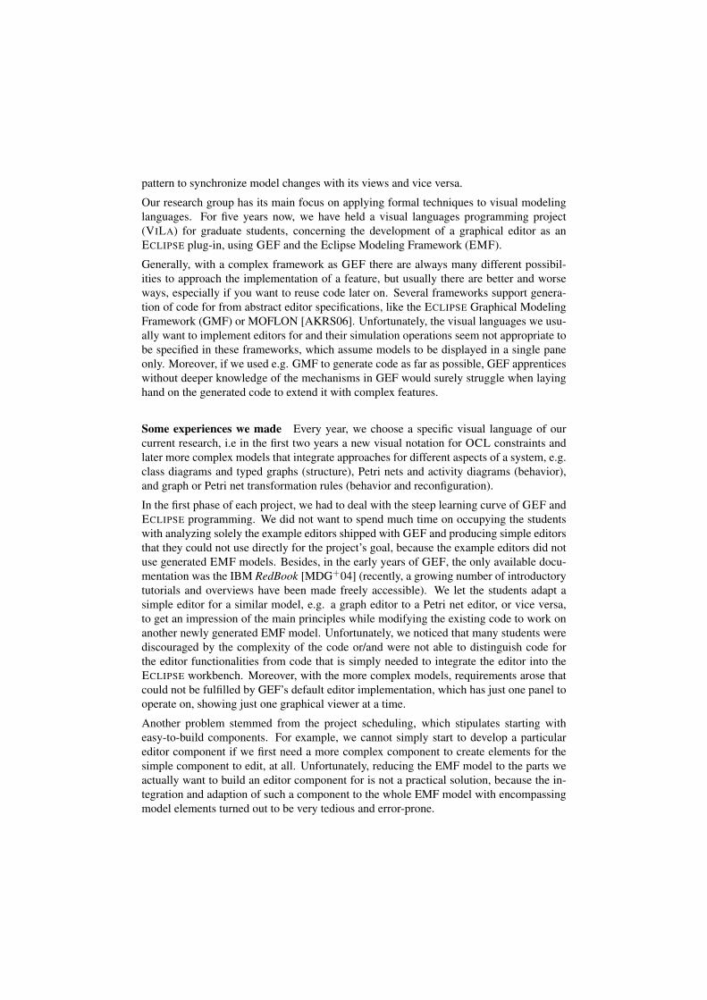
Animated Simulation Petri nets are behavioral models and we want the editors not onlyfor editing but for simulating them as well, i.e. the firing steps, which consume and pro-duce tokens. Continuous animation of the involved tokens would let the user comprehendthe performed firing step better than simple switching to the new system’s configuration.So, we need an easy to integrate mechanism to state that consumed token’s figures shouldmove (by animation) from the incoming places to the firing transition and vanish, whereasthe newly created tokens should appear at the firing transition and then move to their cor-responding places. For an example, see Fig. 2 on the next page where the dashed arrowsshow the animation paths that the consumed and the created tokens will follow during afiring step of the transition.
transition
Figure 2: Example animation for a firing step in a Petri net
Support Stepwise Development and advise Good Practices In addition to the formerfunctional requirements derived from specific visual language features, we also want todeal with the difficulties of getting acquainted with ECLIPSE and GEF and neverthelesswriting coherent code. For this, we would like to support the students by suggesting prac-tices we found useful for producing code that is easy to extend and to maintain.
3 Sample Editors based on MUVITORKIT
In this section, we present two editors based on the MUVITORKIT to demonstrate how torealize our multiple view requirements. The editors are working on complex models thatintegrate approaches for different aspects of a system, e.g. typed graphs, Petri nets, andactivity diagrams (structure); and graph or Petri net transformation rules (behavior andreconfiguration).
3.1 RONEditor for Reconfigurable Object Nets
The visual language of this editor, Reconfigurable Object Nets (RON), are just a variantof the higher-order nets in the previous section, simplified for the VILA students’ project[BEHM07]. RONs are higher-order system nets consisting of transitions (without alge-braic expressions as before, but with fixed semantics) and of places that carry object Petrinet and rule tokens. The editor is freely available [RON].
Fig. 3 on the following page shows a screenshot of the editor with an example RON (aproducer-consumer model for distributed producers and consumers, see [BEHM07] for adetailed explanation). In the left, you see the main tree editor component (1), showingall elements as transitions, places, and tokens on places. (2) is the graphical componentfor editing the RON system net. If you open the editor on a RON file, it will immediatelyshow (1) and (2). This, displaying the tree editor and the graphical view for the mainelement (the ‘top’ element of the model), is the default behavior in all MUVITORKITimplementations.
Consider the place Producers in (2). If you double-click on the token Prod1, GEF trig-gers an ‘open’ request, which by default MUVITORKIT handles such that the graphical
component (3) for the object Petri net will be opened. Similarly, ‘opening’ the rule tokenmergePC on place MergeRules causes the rule editor component (4) to appear. Note thatthis component has a single tool palette shared by three graphical viewers, showing theNAC, LHS, and RHS of the rule.
Opening graphical views for model elements is also always possible in the main tree editorcomponent. The user may double-click entries in the tree to open corresponding graphicalviews, such (3) and (4).
1 2
3
4
Figure 3: Screenshot of the RONEditor
All components (1)-(4) are regular ECLIPSE views that can be arranged in any way. More-over, the RONEditor demonstrates how to define a perspective, so that the components forrules and object nets are automatically arranged as depicted and, if multiple views of thesame kind are opened, they are gathered with tabs as the views for the object nets Prod1,Prod2, and Cons1.
3.2 ActiGra Editor
In the ActiGra model we combined activity diagrams with graph transformation rules asactivities. When simulating an activity diagram, the correspondent rules will be applied toa graph representing some data. In Fig. 4 on the next page, we have again in (1) the all-
encompassing tree view where you can open views for the data graphs, e.g. for PizzaOrderin (2), and for activity diagrams, e.g. for orderPizzaDiagram in (3). Note that rule views,as for orderBeverage in (4), are accesible via the tree view as well as via the activity nodes,e.g. (4) could have been opened by double-clicking the corresponding activity in (3).
1
2
3
4
Figure 4: Screenshot of the ActiGraEditor
4 Structure and Features of the MUVITORKIT
In this section, we describe the MUVITORKIT, its main parts, and how they can be used toquickly build a GEF editor meeting our previously mentioned requirements.
In general, implementing a GEF editor involves two main tasks. On the one hand, youhave to use the GEF architecture to implement EditParts as controllers that mediatebetween a model element and the view part, which are DRAW2D figures, according to theMVC principle. For our models, we use EMF to design the model and to automaticallygenerate code featuring i.a. a qualified notification mechanism. On the other hand, the edi-tor has to be integrated properly into the complex ECLIPSE workbench. To keep the secondtask as simple as possible, MUVITORKIT contains abstract classes for building editors andgraphical classes with GEF’s editing capabilities, which need only the GEF-specific infor-mation to be implemented. In short, most parts that are not GEF-related and integrate theeditor into the workbench are already configured reasonably in MUVITORKIT to provide
many features to every MUVITORKIT implementation with little effort for the developer.Nevertheless, the editor can be controlled via well-documented special methods in the ab-stract classes, following our requirement for encapsulating good practices in simple-to-usemethods3. Note that, in contrast to GMF, where you specify and generate an editor via anabstract model, the aim of MUVITORKIT is to help users with easy-to-use and extendabledefault implementations for building complex GEF editors.
Most generalizations of editor features are only possible because we assume to have agenerated EMF model and make use of the generated code’s special features. The wholeMUVITORKIT framework and its parts are tailored to be used together with an EMF model.
We describe the different parts in detail to give an impression about building an editorbased on MUVITORKIT. At first, let us state a nomenclature: In ECLIPSE, all workbenchcomponents are called ‘views’ and an editor is just a special kind of view with an input.In MUVITORKIT, there is always only one class implementing the ECLIPSE interfaceIEditorPart (see next paragraph), so in the following, we will refer to ‘views’ as thegraphical components that are not the main tree-based view, which we call the editor.In a view or an editor, there may reside several GEF ‘viewers’, which actually displaythe graphical or tree-based representation of the model for editing, and that must not beconfused with ‘views’! In general, view classes have to be registered in the plug-in’sconfiguration file plugin.xml with some identifier to be used in the workbench.
Main Tree Editor The central part of an editor based on MUVITORKIT is an implemen-tation of the abstract class MuvitorTreeEditor. It integrates a basic but comprehen-sive tree-based editor component into the workbench, as a base to access all the graphicalviews for specific model elements from. As for all ECLIPSE editors, this class has to beregistered with the editor extension point of the editor plugin you want to build (i.e. inplugin.xml).
Implementing a subclass of MuvitorTreeEditor is basically connecting the compo-nents responsible for the GEF parts to the editor. For this, there are several abstract meth-ods in which you need to instanciate the following parts: a default EMF model instance(for empty or corrupt files); an EditPartFactory for assigning GEF EditParts toEMF model elements; a ContextMenuProvider for the tree editor component, andoptional some custom actions. See the appendix A.1 for a sample code fragment realizingthe RONEditor. Implementing the edit part factory and the context menu provider is pureGEF developing; there is no need for the developer to deal with workbench integration atthis point.
There are other methods to realize further editor features as well, but this is the necessaryset. In addition, you need to associate the types of EMF model elements (e.g. graphs, Petrinets etc.) that you want to display graphically to appropriate views. We will see later howto implement these views and how they can be opened via the MuvitorTreeEditor’sshowView mechanism.
All MuvitorTreeEditors, even resulting from minimal implementations, have the
3In this way, the students can first simply use the API (after we advised them of the corresponding methods) toimplement basic features and later analyze and extend parts of the code selectively with more complex features.
following features:
• When opened, the editor activates a perspective (general layout for the views onthe workbench) if optionally registered in plugin.xml. When closed, it restores theprevious perspective and remembers all currently opened graphical views. Theseare reopened when the editor is activated again.
• A manager for persistency operations on EMF models is provided and handled prop-erly. No additional load and save implementations are needed.
• Most generic actions provided by ECLIPSE and GEF are automatically installed tothe action bars as save, save as, undo, redo, print, direct edit, delete, alignment,revert. MuvitorTreeEditor automatically takes care about updating the statesof these actions properly. A basic revert mechanism allows to reload the model fromthe current file.
• If the developer lets the editor create special problem markers, editor users may‘open’ these in the ECLIPSE Problem View, which causes the editor to be activated(if necessary) and to display and to select the problematic part of the model via theshowView mechanism.
• Registering the class MuvitorFileCreationWizard with the new wizard ex-tension point in plugin.xml is all you need for a wizard dialog that creates a newempty file. MuvitorTreeEditor fills this with the empty default model. The fileextension to which the editor is bound is retrieved automatically from plugin.xml.
• Several special technical adjustments are made for better support of the multi viewconcept, e.g. to keep the editor’s action bar enabled if the user selects something ina graphical view.
Graphical Views Using MUVITORKIT, the main editor can open different views forcertain types of model elements (e.g. for the graphs, Petri nets, rules etc.) that support anarbitrary number of (GEF) viewers hosted inside a view (e.g. a view for transformationrules containing two viewers displaying the rule’s LHS and RHS, maybe even with a thirdone displaying a NAC).
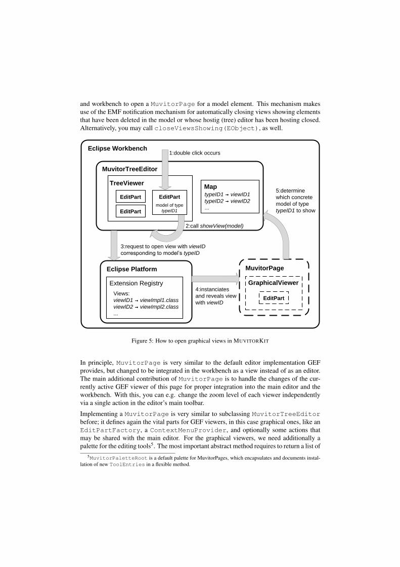
MuvitorPage is an abstract implementation of an ECLIPSE view that is prepared to beopened via the method MuvitorTreeEditor.showView(EObject)4. If the EMFmodel type of the passed EObject (i.e. its EClass) has been assigned to the identifierof a registered (in plugin.xml) view, calling this method will open the correponding viewand make the EObject accessible for this view. See Fig. 5 on the following page for adiagram outlining how the MuvitorTreeEditor interacts with the ECLIPSE platform
4Strictly speaking, MuvitorPage itself is not an ECLIPSE view (implementing IViewPart) but it con-tains all the editing functionality. MUVITORKIT provides an abstract class MuvitorPageBookView, whichhas to be implemented for each MuvitorPage and has to be registered in the plugin.xml. It is very easy to im-plement and its sole purpose is to host MuvitorPage instances. This is a rather technical construction ECLIPSEdemands, so in the following we consider the MuvitorPage as the view.
and workbench to open a MuvitorPage for a model element. This mechanism makesuse of the EMF notification mechanism for automatically closing views showing elementsthat have been deleted in the model or whose hostig (tree) editor has been hosting closed.Alternatively, you may call closeViewsShowing(EObject), as well.
Eclipse Platform
Extension Registry
Views:
viewID1 viewImpl1.class
viewID2 viewImpl2.class
...
MuvitorTreeEditor
TreeViewer
EditPart EditPart
MuvitorPage
model of type
typeID1EditPart
MaptypeID1 viewID1
typeID2 viewID2
...
1:double click occurs
2:call showView(model)
3:request to open view with viewID
corresponding to model’s typeID
4:instanciates
and reveals view
with viewID
5:determine
which concrete
model of type
typeID1 to show
GraphicalViewer
EditPart
Eclipse Workbench
Figure 5: How to open graphical views in MUVITORKIT
In principle, MuvitorPage is very similar to the default editor implementation GEFprovides, but changed to be integrated in the workbench as a view instead of as an editor.The main additional contribution of MuvitorPage is to handle the changes of the cur-rently active GEF viewer of this page for proper integration into the main editor and theworkbench. With this, you can e.g. change the zoom level of each viewer independentlyvia a single action in the editor’s main toolbar.
Implementing a MuvitorPage is very similar to subclassing MuvitorTreeEditorbefore; it defines again the vital parts for GEF viewers, in this case graphical ones, like anEditPartFactory, a ContextMenuProvider, and optionally some actions thatmay be shared with the main editor. For the graphical viewers, we need additionally apalette for the editing tools5. The most important abstract method requires to return a list of
5MuvitorPaletteRoot is a default palette for MuvitorPages, which encapsulates and documents instal-lation of new ToolEntries in a flexible method.
EObjects as viewer contents, each to be displayed in an own viewer on this page. For ex-ample to show a rule as mentioned before, if the view has been opened via showView(rule),the returned list must contain rule.getNAC(), rule.getLHS(), and rule.getRHS(). See the ap-pendix A.2 for a sample code fragment realizing the RONEditor’s rule component.
Furthermore, there are additional API methods e.g. for hiding single viewers, e.g. if youdelete the NAC of a rule.
The main additional contribution of MuvitorPage is to handle the changes of the cur-rently active GEF viewer of this page for proper integration into the main editor and theworkbench. With this, you can e.g. change the zoom level of each viewer independentlyvia a single action in the editor’s main toolbar.
MuvitorPages are designed to be able to reuse actions that have been created in themain editor, like the generic copy and paste action in RulePage, and updating actions ishandled similarly to the MuvitorTreeEditor.
Furthermore, there are additional API methods e.g. for hiding single viewers, e.g. if youdelete the NAC of a rule.
By implementing MuvitorPage you get features for free again, in this case a number ofgeneric actions that work as they are in every single GEF viewer of the page:
• ExportViewerImageAction exports the components contents into a graphic file.TrimViewerAction moves the figure in the upper left corner so that the viewer’s sizeis minimized but still showing all figures.
• GenericGraphLayoutZESTAction and GenericGraphLayoutAction apply the ZESTor DRAW2D graph layout algorithms to the selected component.
• MoveNodeAction changes the location of selected nodes by keys.
• SelectAllInMultiViewerAction selects all parts in the current viewer.
• GenericCopyAction copies any EMF model in form of a serialized String into thesystem’s clipboard. GenericPasteAction pastes the clipboard into the current editpart’s EMF model if allowed. Supports undo operation and derinition of flexiblePasteRules, e.g. to prevend rule tokens to be pasted into system net places for objectnets and vice versa.
• MuvitorToggleGridAction and MuvitorToggleRulerVisibilityAction toggle the gridand ruler visibility of a viewer.
Implementing EditParts as Controllers Now that we have the main editor and theviews, we need to some place to invoke the showView mechanism. For this, MUVITORKIToffers its own extended EditParts called AdapterEditParts, which are the con-trollers of the elements displayed in the GEF viewers and which are supposed to be usedexclusively in MUVITORKIT. Besides other enhancements6, by default they call showView
6E.g. to support closing the views for deleted models, and providing a generic EObjectPropertySourcefor the Properties View, showing all of the model’s attributes and their values.
on their model if they receive GEF’s open request, which is dispatched to an edit part whena double-click occurs on it (see the first step in Fig. 5 on page 10). This is the key to thebehavior of the MUVITORKIT examples we described in Sect.3: we configure the viewscorrectly and associate them with the types of elements they are supposed to display andwe use these special AdapterEditParts. The types of models (rules, nets etc.) can bearbitrarily nested and we can navigate as deep as we want, as long as we have an edit partfor a closed representation of each nested part, like a rule token, and a view for its detailedrepresentation like the rule view.
Figure 6: Direct Editing with validator for unique node names
An editing feature, useful for almost all edit parts, is direct editing of a name or someother attribute value. In previous projects, we commissioned one of the student groupsto give a little lecture about how to implement this features as this is not a trivial task.With presuming an EMF model, we could generalize and encapsulate this feature to allAdapterEditParts. All we need to do is to let a custom edit part implement ourinterface IDirectEditPart, which just has one mandatory method that returns theEMF identifier of the model’s attribute that should be edited7. This is all information theedit part needs to run a direct edit manager as in Fig. 6. Optionally, you may specify avalidator checking the input and generating an error message as in this picture.
Some additional supporting MUVITORKIT classes MappingCreationTool is aspecial GEF ConnectionCreationTool, allowing connections between parts in dif-ferent viewers like the relation of places and transitions in the Petri nets of a transformationrule. In contrast to the regular ConnectionCreationTool this tool remains in validstate when the mouse leaves the viewer’s border.
Registering the class MuvitorFileCreationWizard with the new wizard extensionpoint in plugin.xml is all you need for a wizard dialog that creates a new empty file.MuvitorTreeEditor fills this with the empty default model. The file extension towhich the editor is bound is retrieved automatically from plugin.xml.
The class IconUtilTemplate proposes a universal way to access image files in theproject path via definable keys and uses the caching mechanism of the plug-in’s ImageRegistry.
7e.g. EcorePackage.ENAMED ELEMENT NAME
5 A Package for Defining Functional Animations
MUVITORKIT supports the definition of continuous animations for selected model ele-ments. The main class in the animation package is AnimatingCommand, which canbe given information about how some model elements (EMF EObjects), visualized byfigures in a graphical viewer, should be animated8. For this, you specify stepwise absolute(Points) or relative (some model elements) locations and optional size factors for themodel elements to be animated.
Why not use GEF’s Animation Mechanism? GEF also contains classes Animatorand Animation, which can be used to animate figures, i.e. sliding a figure on a straightpath to the new location it is set to. The following main advantages of using MUVI-TORKIT’s animation package instead allow to specify more powerful animations moreflexibly:
• You can specify which model element to animate instead of the corresponding figure.This means that you can specify animations independently from actual viewers andmodel states, and rely on the package’s mechanism to find the corresponding figuresautomatically at animation runtime.
• Several elements can be animated independently along complex paths with flexibletiming/speed (by interpolating intermediate steps). You can even alter the animationpaths to sine, circle, or elliptic curves.
• Each animated figure can be zoomed smoothly while it moves on its path, accordingto absolute size factors. Such figures resize independently of all other (possiblyanimated) figures in the same viewer.
• You can easily specify parallel animations in several independent viewers.
• You can easily integrate your animation definitions into the Commands your ed-itor invokes to change the model on editor operations. Moreover, Animating-Command automatically takes care of reversing performed animations to supportthe ‘undo’ operation.
We provide a detailed tutorial example of the documentation of AnimatingCommand[RON] in appendix B.
8According to the MVC principle, we strictly distinguish a model element (some EMF EObject instance)from its ‘figure’, which is just its graphical representation in GEF viewers
6 Conclusion
We presented MUVITORKIT, a framework to facilitate the implementation of rich-featuredGEF editors, and described the important aspects of this framework’s main classes andhow they can be used to build editors for complex visual languages consisting of differentnested components. Many more details about benefits of using MUVITORKIT can befound in the Java documentation of its classes.
We are permanently extending the MUVITORKIT. When our students come up with usefulfeatures in the projects or have feature requests, we try to generalize them in MUVITORKITif possible or to include at least a documented example implementation in the RONEditor.
Future Work We plan to extend the MUVITORKIT by further features and to eliminatesome minor deficiencies:
• When developing custom editor plugins based on MUVITORKIT, each editor has toreference its own exclusive copy of the MUVITORKIT plugin in its dependencies.This is due to the fact that the mechanisms accessing the editor’s plugin registryare located in MUVITORKIT. Generalization is possible but would impose morepreparation steps when implementing a custom editor on the developer.
• The animation package is going to be restructured to support more animation-relatedaspects like highlighting figures and annotating them with other figures like labelsduring animation.
References
[AKRS06] C. Amelunxen, A. Konigs, T. Rotschke, and A. Schurr. MOFLON: A Standard-Compliant Metamodeling Framework with Graph Transformations. In A. Rensink andJ. Warmer, editors, Model Driven Architecture - Foundations and Applications: SecondEuropean Conference, volume 4066 of Lecture Notes in Computer Science (LNCS),pages 361–375, Heidelberg, 2006. Springer Verlag, Springer Verlag.
[BEHM07] E. Biermann, C. Ermel, F. Hermann, and T. Modica. A Visual Editor for ReconfigurableObject Nets based on the ECLIPSE Graphical Editor Framework. In Proc. 14th Work-shop on Algorithms and Tools for Petri Nets (AWPN’07). GI Special Interest Group onPetri Nets and Related System Models, 2007.
[HME05] K. Hoffmann, T. Mossakowski, and H. Ehrig. High-Level Nets with Nets and Rulesas Tokens. In Proc. of 26th Intern. Conf. on Application and Theory of Petri Nets andother Models of Concurrency, volume 3536, pages 268–288. 2005.
[MDG+04] B. Moore, D. Dean, A. Gerber, G. Wagenknecht, and P. Vanderheyden. Eclipse Devel-opment using the Graphical Editing Framework and the Eclipse Modeling Framework.IBM Corporation, International Technical Support Organization, 2004.
[RON] Website of the RONEditor and MUVITORKIT. http://tfs.cs.tu-berlin.de/roneditor.
[Val98] R. Valk. Petri Nets as Token Objects: An Introduction to Elementary Object Nets. InICATPN ’98: Proceedings of the 19th International Conference on Application andTheory of Petri Nets, volume 2987 of LNCS, pages 1–25. Springer, 1998.
A Sample code fragments from the RONEditor
A.1 Example for RONTreeEditor
p u b l i c c l a s s RONTreeEditor ex tends M u v i t o r T r e e E d i t o r {s t a t i c S t r i n g ob jec tNe tViewID = ” ObjectNetPageBookView ” ;s t a t i c S t r i n g ru leViewID = ” RulePageBookView ” ;s t a t i c S t r i n g ronViewID = ”RONPageBookView” ;
/ / d e f i n e t h e v i e w s f o r s p e c i f i c EMF model e l e m e n t s{ r e g i s t e r V i e w I D ( RonmodelPackage . L i t e r a l s .RON, ronViewID ) ;
r e g i s t e r V i e w I D ( RonmodelPackage . L i t e r a l s . RULE, ru leViewID ) ;r e g i s t e r V i e w I D ( RonmodelPackage . L i t e r a l s . OBJECT NET ,
ob jec tNe tViewID ) ;}
/ / c r e a t e d e f a u l t model f o r empty or c o r r u p t f i l e sp r o t e c t e d EObjec t c r e a t e D e f a u l t M o d e l ( ) {
RON newRon = RonmodelFac tory . eINSTANCE . createRON ( ) ;newRon . setName ( ”<d e f a u l t >” ) ; re turn newRon ;
}
/ / f a c t o r y f o r a s s i g n i n g GEF E d i t P a r t s t o model e l e m e n t sp r o t e c t e d E d i t P a r t F a c t o r y c r e a t e T r e e E d i t P a r t F a c t o r y ( ) {
re turn new R O N T r e e E d i t P a r t F a c t o r y ( ) ;}
/ / d e f i n e a c o n t e x t menu f o r t h e t r e e e d i t o r componentp r o t e c t e d [ . . . ] c r e a t e C o n t e x t M e n u P r o v i d e r ( TreeViewer v ) {
re turn new RONEdi torContex tMenuProvider ( v , g e t A c t i o n R e g i s t r y ( ) ) ;}
/ / c r e a t e some a d d i t i o n a l a c t i o n s f o r t h e e d i t o rp r o t e c t e d void c r e a t e C u s t o m A c t i o n s ( ) {
r e g i s t e r A c t i o n ( new Gener i cCopyAct ion ( t h i s ) ) ;r e g i s t e r A c t i o n ( new G e n e r i c P a s t e A c t i o n ( t h i s ) ) ;
} } / / end c l a s s
A.2 Example for RulePage
p u b l i c c l a s s RulePage ex tends Muvi to rPage {
/ / d e f i n e a c o n t e x t menu f o r t h e r u l e e d i t o rp r o t e c t e d [ . . . ] c r e a t e C o n t e x t M e n u P r o v i d e r ( E d i t P a r t V i e w e r v ) {
re turn new RulePageCon tex tMenuProv ide r ( v , g e t A c t i o n R e g i s t r y ( ) ) ;}
/ / s h a r e a d d i t i o n a l a c t i o n s from t h e e d i t o rp r o t e c t e d void c r e a t e C u s t o m A c t i o n s ( ) {
r e g i s t e r S h a r e d A c t i o n A s H a n d l e r ( A c t i o n F a c t o r y .COPY. g e t I d ( ) ) ;r e g i s t e r S h a r e d A c t i o n A s H a n d l e r ( A c t i o n F a c t o r y . PASTE . g e t I d ( ) ) ;
}
/ / d e f i n e a p a l e t t e w i t h e d i t o r t o o l sp r o t e c t e d M u v i t o r P a l e t t e R o o t c r e a t e P a l e t t e R o o t ( ) {
re turn new R u l e P a l e t t e R o o t ( ) ;}
/ / t h i s a r r a y d e t e r m i n e s number and c o n t e n t s o f t h e v i e w e r sp u b l i c EObjec t [ ] g e t V i e w e r C o n t e n t s ( ) {
Rule r u l e = ( Rule ) getModel ( ) ;re turn new EObjec t [ ] {
r u l e . ge tNac ( ) , r u l e . ge t Lh s ( ) , r u l e . ge tRhs ( ) } ;}
/ / f a c t o r y f o r a s s i g n i n g GEF E d i t P a r t s t o model e l e m e n t sp r o t e c t e d E d i t P a r t F a c t o r y c r e a t e E d i t P a r t F a c t o r y ( ) {
/ / r e u s e f a c t o r y because l h s , rhs , and nac are o b j e c t n e t sre turn new O b j e c t N e t E d i t P a r t F a c t o r y ( ) ;
} } / / end c l a s s
B Stepwise Animation Definition - an Example
To illustrate the principle of stepwise animation definition, we discuss the example timeschedule matrix below. It represents the definition of an animation of three arbitrary modelelements (element1-3). We have a column for each element to be animated and a rowfor each defined animation step, each with a positive integer value d1-3 representing theduration of this step in msecs (except for the first, which is the starting position row):
First, you have to understand what the performed animation will look like. After that youshall see how you can define this animation with an AnimatingCommand.
In short, each table entry tells when (after the sum of durations till this step) the figureof the column’s element has to at a specific absolute or relative location. For example,element1 is supposed to start at its own original position, to move in d1 msecs to theposition of element2, after that to move in d2 msecs to the position of element3, and toreturn in d3 seconds back to its initial position.
Note that when specifying relative locations, they will be resolved to the absolute loca-tions that the related figure has before the animation. Thus, element1’s figure will moveto the locations of element2’s and element3’s figures that they have before the anima-tion, even if these will be animated themselves in this particular animation. Of course,only those elements will be animated, for which a figure (being related to this elementby some EditPart) can be found. There is no need for element1-3 having figures inthe same viewer at command-execution nor command-definition time, but only figures inopen viewers that exist at execution-time will be animated. AnimatingCommand willnot regard it as an error if no figure can be found for an element at all.
Let’s continue with element2 to understand step interpolation: As you can see in the table,only an absolute starting position and a position after the third step has been specified.Generally, undefined steps between defined steps will be interpolated linearly. So, after d1msecs element2’s figure would reach the point (33,33), after d1+d2 msecs (66,66),and finally (100,100). Note that an animation of a particular figure always starts at thefirst specified step and ends at the last specified step. If no start or end location for thewhole path of a model’s figure can be resolved or interpolated, it will not be animated atall, but also no error message will be raised.
How element3’s figure would be animated should be obvious by now. Now we implementthis animation. Suppose we have a container model element parent, being the contents ofa viewer (e.g. a Petri net), and we want to animate the figures for element1-3 (e.g. placesor tokens):
AnimatingCommand aniComm = new AnimatingCommand ( ) ;/ / i n i t i a l i z e o b j e c t s f o r a n i m a t i o naniComm . i n i t i a l i z e A n i m a t e d E l e m e n t ( e lement1 , p a r e n t , n u l l ) ;aniComm . i n i t i a l i z e A n i m a t e d E l e m e n t ( e lement2 , p a r e n t , n u l l ) ;/ / s p e c i f y s t a r t i n g p o s i t i o naniComm . s p e c i f y S t e p ( e lement1 , e l e m e n t 1 ) ;aniComm . s p e c i f y S t e p ( e lement2 , new P o i n t ( 0 , 0 ) ) ;/ / f i n i s h ” s t a r t i n g s t e p ” , d e c l a r e n e x t s t e p w i t h d u r a t i o n d1aniComm . n e x t S t e p ( d1 ) ;/ / s p e c i f y s t e p 1aniComm . s p e c i f y S t e p ( e lement1 , e l e m e n t 2 ) ;aniComm . i n i t i a l i z e A n i m a t e d E l e m e n t ( e lement3 , p a r e n t , n u l l ) ;aniComm . s p e c i f y S t e p ( e lement3 , e l e m e n t 1 ) ;/ / f i n i s h d e f i n i t i o n o f s t e p 1 , d e c l a r e s t e p w i t h d u r a t i o n d2aniComm . n e x t S t e p ( d2 ) ;/ / s p e c i f y s t e p 2aniComm . s p e c i f y S t e p ( e lement1 , e l e m e n t 3 ) ;aniComm . s p e c i f y S t e p ( e lement3 , e l e m e n t 2 ) ;/ / f i n i s h d e f i n i t i o n o f s t e p 2 , d e c l a r e s t e p w i t h d u r a t i o n d3aniComm . n e x t S t e p ( d3 ) ;
/ / s p e c i f y s t e p 3aniComm . s p e c i f y S t e p ( e lement1 , e l e m e n t 1 ) ;aniComm . s p e c i f y S t e p ( e lement2 , new P o i n t ( 1 0 0 , 100) ) ;
In this short code snippet, we first create a plain AnimatingCommand and declare ele-ment1 and element2 as to be animated in the viewer that ’shows parent’, i.e. that has parentas contents. This must be done for an element before specifying any steps for it. The lastparameter (null) can optionally alter the path curve form. Now, look at the matrix tableabove again: In the first step (which you have to imagine always as initial placement of theanimated figures, i.e. happening with the duration 0msec) we specify element1’s and ele-ment2’s figures to be at the location of the element1’s figure of itself and at Point(0,0),respectively.
With this we have completed the specification of the first step and can proceed to the nextstep by calling nextStep(d1), which states that the next step should take d1 msecsto complete. The next row in the table says that in this step element1’s figure shouldmove to the original position of element2’s figure, and that element3’s figure should startits animation at the original position of element1’s figure. For this we have to initializeelement3 belatedly. It should be clear by now, how the remaining lines correspond to thetable entries.
Optional Animation Features Additionally, you may specify a size factor (relativeto the figure’s original size) for each step via specifyStep(Object, Object,double) that will affect the figure’s size at this step’s location. A value of -1 will markthis element’s size factor as to be interpolated for the current step for a smooth animation,similar to the locations.
With setDebug(boolean) you can force the figures to mark their animation path witha red line, which will remain visible after animation.