Page 1
Konya Mühendislik Bilimleri Dergisi, c. 9, s. 3, 809-835, 2021
Konya Journal of Engineering Sciences, v. 9, n. 3, 809-835, 2021
ISSN: 2667-8055 (Elektronik)
DOI: 10.36306/konjes.907309
AN ECONOMIC AND TECHNICAL REVIEW FOR THE UTILIZATION OF HVDC IN TURKEY
AND IN THE WORLD
1Hakan ACAROĞLU , 2Atabak NAJAFI , 3Ömer KARA , 4Burcu YÜRÜK 1,3Eskisehir Osmangazi University, Economics and Administrative Sciences Faculty, Economics Department,
Eskisehir, TURKEY 2Eskisehir Osmangazi University, Engineering and Architecture Faculty, Electrical and Electronics Engineering
Department, Eskisehir, TURKEY 4Usak University, Accounting and Finance Management Department, Usak, TURKEY
[email protected] , [email protected] , [email protected] , [email protected]
(Geliş/Received: 31.03.2021; Kabul/Accepted in Revised Form: 15.06.2021)
ABSTRACT: In recent years, it is seen that High Voltage Direct Current (HVDC) transmission line systems
have come to the fore in the field of energy efficiency in the world. Therefore, it is predicted that analyzing
the technological and economic advantages of HVDC transmission line systems will make an important
contribution to energy efficiency policies. In this regard, this study aims to examine the technological and
economic advantages of HVDC transmission systems through the historical development with
applications in Turkey and in the world. In addition to this, it is expected that the evaluation of the effects
of energy efficiency on the economy will bring a different perspective to the energy and economic
literature. Therefore, it is thought that energy and economic policies for the spread of HVDC transmission
line systems worldwide will be essential. The asymmetric distribution of natural energy sources in the
world causes energy supply security problems in the countries such as Turkey in terms of high foreign
dependence on energy. For this reason, it is necessary to meet the increasing energy demand and increase
the existing capacity day by day. Besides, it is important to develop policies for efficient use of energy.
HVDC technology is extremely important for a developing country like Turkey. Moreover, it is known
that this energy transmission technology has become widespread in developed countries. Thereby, a
technical comparison is done for investment costs of the transmission system in Germany. As a result,
other than bringing economic benefits with the energy transmission of Turkey through HVDC, it has
important potential for making energy transmission possible with her neighbors and European Union
countries.
Key Words: High voltage direct current, Transmission line system, Energy, Turkey
Yüksek Gerilim Doğru Akım (YGDA) İletim Hatlarının Türkiye ve Dünyada Kullanımına İlişkin
Ekonomik ve Teknik Bir İnceleme
ÖZ: Son yıllarda dünyada enerji verimliliği alanında Yüksek Gerilim Doğru Akım (YGDA) iletim hattı
sistemlerinin ön plana çıktığı görülmektedir. Bu nedenle, YGDA iletim hattı sistemlerinin teknolojik ve
ekonomik üstünlüklerinin analiz edilmesinin enerji verimliliği politikalarına önemli bir katkı sağlayacağı
öngörülmektedir. Bu bağlamda bu çalışma, YGDA iletim hattı sistemlerinin, Türkiye’de ve dünyada
tarihsel gelişimi ile uygulama örnekleri üzerinden teknolojik ve ekonomik avantajlarının incelenmesini
amaçlamaktadır. Buna ek olarak, çalışmada enerji verimliliğinin ekonomi üzerindeki etkilerinin
değerlendirilmesinin, enerji ve ekonomi literatürüne farklı bir bakış açısı getireceği beklenmektedir.
Böylece, YGDA iletim hattı sistemlerinin dünya genelinde yaygınlaşmasına yönelik enerji ve ekonomi
Page 2
810 H. ACAROĞLU, A. NAJAFI, Ö. KARA, B. YÜRÜK
politikalarının önem kazanacağı düşünülmektedir. Dünyada doğal enerji kaynaklarının asimetrik
dağılımı, Türkiye gibi enerjide dışa bağımlılığı yüksek olan ülkeler açısından enerji arz güvenliği
sorununa neden olmaktadır. Bu sebeple her geçen gün artan enerji talebinin karşılanması ve mevcut
kapasitenin artırılması gerekmektedir. Ayrıca, enerjinin verimli kullanılmasına yönelik politikaların
geliştirilmesi de önem taşımaktadır. YGDA teknolojisi Türkiye gibi gelişmekte olan bir ülke için son
derece önemlidir. Ayrıca gelişmiş ülkelerde bu enerji iletim teknolojisinin yaygınlaştığı bilinmektedir. Bu
nedenle, Almanya’daki bir iletim sisteminin yatırım maliyetleri için teknik bir karşılaştırma yapılmıştır.
Sonuç olarak, Türkiye’nin enerji iletimini YGDA ile sağlaması ekonomik getirilerinin yanı sıra, komşu ve
Avrupa Birliği ülkeleriyle enerji iletimini mümkün kılması açısından ekonomik bir potansiyel de
taşımaktadır.
Anahtar Kelimeler: Yüksek gerilim doğru akım, İletim hattı sistemi, Enerji, Türkiye.
1. INTRODUCTION
Demand for electrical energy, which is an important production input alongside labor and capital,
continues to increase worldwide day by day. Especially in developing countries including Turkey, foreign
dependence on energy leads to an increase in the current deficit by playing an import increasing role in
meeting the growing demand. This situation affecting the economy reveals the necessity of countries to
handle their energy policies with economic policies. In recent years, it is observed that the policies of
countries to reduce foreign dependency and increase their existing production capacity have accelerated
for each country in order to meet the increasing demand. In this context, not only the capacity increase
but also ensuring the efficiency of existing capacity contributes to the rapid development of transmission
line technologies. When the historical process is analyzed, it is seen that the electrical energy transmission
and distribution, which is used extensively, is realized as alternating current (AC) and direct current (DC).
The network development in different periods varies in terms of voltage class, network size, generator
unit capacity, and technical and economic aspects due to the developments in transmission technologies
over time. Based on these aspects, the history of the network development can be separated into different
phases. From the end of nineteenth century to the midst of the twentieth century, the electrical network
became prominent with the usage of AC in production and transmission as well as its distribution. It was
the first phase that ceased with the end of the World War II. During this phase, the generator unit capacity
was less than 200 MW; AC transmission was prevailing only up to 220 kV (Liu, 2014).
Higher voltage transmission systems that are needed in this period and become widespread over
time can be classified as high voltage (HV-35-220kV), extra-high voltage (EHV-330-1000kV), and ultra-
high voltage (UHV-1000kV and more) (Long and Nilsson, 2007). The implementation of electricity
transmission, which is used extensively today, with the least cost and transmission loss is of great
importance in terms of ensuring energy efficiency and positive effects on the national economies.
It is observed that the use of HVDC transmission line systems has become widespread with its
technological and economic advantages, and parallel to this, studies on HVDC transmission line systems
have also become widespread. When these studies are examined, it is seen that studies especially on
technical aspects such as the integration of HVDC transmission lines into existing AC networks (Brask,
2008; Burger and Tuson, 2005), effects on network reliability and development (Kotb, 2018; Stenberg,
2013), functionality of HVDC converter at world stations (Almgren et al., 1998; Beerten et al., 2014),
reliability of test systems (Bertling and Pramod, 2011), VSC (voltage source converter)-HVDC modeling
(Träff and Lennerhag, 2013), location determination for in-network application (Shuai, 2012) and
applicability at distribution level (Giraneza, 2013) become prominent. In a limited number of studies
evaluating the market structure, geographical distribution, and technical/economic superiority of HVDC
transmission line systems, it is seen that the subject has been examined within the scope of engineering
science (Alassi et al,, 2019; Gamit et al., 2015; Rudervall et al., 2000). It is seen that the studies focused on
the details of HVDC transmission line systems are generally focused on their applications in China (Mircea
and Philip, 2017; Cao and Cai, 2013; Pudney, 2012).
Page 3
An Economic and Technical Review for the Utilization of HVDC in Turkey and in the World 811
In this interdisciplinary study, the technological and economic advantages of HVDC transmission
line systems are evaluated within the scope of engineering and economics. Thereby, a technical
comparison is shown for investment costs of the transmission system in a developed country: Germany.
Finally, other than bringing economic benefits with the energy transmission of Turkey through HVDC, it
has important potential for making energy transmission possible with Turkey’s neighbors and European
Union countries. It is thought that this study will give a different perspective to the literature especially
with its evaluations regarding the energy efficiency of HVDC transmission line systems and its role in
reducing foreign dependence on energy in the future. In addition, it is anticipated that this study will
contribute to the joint evaluation of energy and economic policies to be developed for the applicability of
HVDC transmission line technologies in countries with high foreign dependence on energy, especially in
Turkey.
2. HIGH VOLTAGE CLASSES: ADVANTAGES VERSUS DISADVANTAGES
Historically, when examining high voltage classes, HVAC has been the major transmission
technology that benefited from the initial advancement of AC transformers. It is because AC allows the
HVAC transmission for longer distances and lower losses, as well as "Current Wars" resulting in favor of
Tesla. Nonetheless, with the development of mercury arc valves and their prevailing adoption in the 1930s
and HVDC allowing energy to be transmitted at higher voltages, DC has entered the transmission market
again (Alassi et al., 2019). The advantages versus disadvantages of HVDC can be found as follows:
HVDC Advantages:
Lowering line cost as HVDC transmission requires fewer conductors; for example, two conductors
are used for a typical bipolar HVDC line compared to three-phase HVAC.
HVDC transmission lines cause reduction of Corona losses compared to HVAC of similar power.
As HVDC can carry more power per conductor of given size, there is a reduction of the wiring
and strut profile for a given power transmission capacity.
HVDC uses power electronic systems in transmission lines. Since these devices have no
mechanical moving parts, there is less probability of failure, so have very robust performance and
long life under the nominal conditions.
It is an undeniable fact that the least harmful transmission to the environment is DC transmission.
Less losses on DC lines makes DC transmission a more efficient system.
With the HVDC system, the power flow can be controlled quickly and precisely both the power
level and the direction. HVDC Disadvantages:
HVDC transmission lines are expensive because they are needed in rectifier and inverter circuits.
In addition, since power electronics elements are used, it will cause harmonic increase on the line. A
suitable filter needs to be designed to solve this problem.
Disconnection of direct current in HVDC transmission lines is more difficult.
Since power electronics circuits are used, control systems are complex and require expertise.
It can be set up between two points. No addition can be made to the desired point of the line.
3. HVDC TRANSMISSION LINES
3.1. The Development of HVDC Transmission Lines in History
HVDC transmission lines are generally less costly than HVAC for transmission distances of more
than 600 km (and power above 1000MW) (Figueroa-Acevedo et al., 2015). In cases where the HVDC power
transmission is up to 600-800M, approximately 300 km distances have been reached. Underwater cables
and cable lengths up to approximately 1000 km are in the planning phase. As mentioned earlier, HVDC
power transmission technology over long distances was introduced in the second half of the last century.
From initial installations that allow less than 100MW of power transmission, the transmission capacity is
Page 4
812 H. ACAROĞLU, A. NAJAFI, Ö. KARA, B. YÜRÜK
constantly increasing towards higher values (Mazzanti and Marzinotto, 2013). In order to overcome the
technical limitations on reactive power demand of HVAC cables for long distances, the first commercial
applications of HVDC transmission are produced, especially in underwater transmission. Later, HVDC
has been applied for long-distance air lines and it has been found that it offers cost-effective solutions
compared to HVAC technology as the transmission distance increases. Moreover, it is seen that the lower
cost structure of HVDC compared to HVAC has played an important role in the development of HVDC
transmission lines over time.
When important projects in the first period developments of HVDC are examined, it is seen that
a 115 km long underground cable system, providing 60MW power with 200 kV voltage value and 150A
cable amp, to Berlin, Germany was ready to be energized in 1945 but it was never employed due to the
events related to World War II. In 1952, a transmission line of 110 kV was constructed in China by her own
technologies (Tiku, 2014). In 1954, 220 kV Fengman-Lishizhai line was constructed. In 1956, the
Kuybyshev-Moscow transmission line became operational in the Soviet Union, making it the world's first
application of 500 kV in transmission (Ukil, 2015). In 1965, the World's first 735 kV transmission line,
between Quebec City and Montreal, was completed. A 750 kV pilot transmission line in the Soviet Union
and a 765 kV transmission line in the United States were constructed in 1967 and 1969 respectively.
It is observed that the power capacity and transmission line lengths have increased with the
developments in the first period of HVDC as it is happening today. For instance, Sardinia Peninsula Italy
(SAPEI) HVDC interconnection is a bipolar system used for 1000MW transmission over 440M cable length,
which is known as the longest project in the world as of today. It connects Fiumesanto, which is 1650 m
below sea level in the Tyrrhenian Sea, to Sabotino (Mazzanti and Marzinotto, 2013).
3.1.1. Development of HVDC Transmission Lines in the World
When the geographical distribution of HVDC transmission systems in the world is examined, it is
seen that the Asian continent takes the first place. Many HVDC projects, especially in this continent where
China and India are located, have been built in order to provide efficiency in the transmission of energy
to long distances because of the geographical width of those countries. Especially in China, it is seen that
the current connections exceed 10000MW. It is seen that Asia has the largest average transmission voltage
since most of the HVDC connections established after 2010 have been ± 800 kV, which has increased
recently. The European continent follows the Asian continent in the configuration of the HVDC projects.
However, considering the demand and geographical differences of HVDC connections in Europe, it is
seen that higher power and longer distances are not required compared to the Asian continent and 1.1
GW cross-border connections are dominant (L’Abbate et al., 2015). Asia and Europe are followed by North
America with 1.5 GW capacity, South America with 1.4 GW capacity and other regions with 1.0 GW
capacity, in order (Alassi et al., 2019). When the geographical distribution of the maximum voltage reached
in HVDC transmission line systems is examined, the continent of Asia with the highest voltage
transmission (1100 kV) is followed by the continent of South America with 800 kV, the continents of
Europe and North America with 600 kV, and other continents with 500 kV, in order (Liu et al., 2018). When
the market of HVDC transmission line systems in the world is analyzed, ABB, which has been providing
service for 60 years, dominates more than half the market. Along with ABB, Siemens and Alstom Grid
(General Electric since 2015) has emerged as other important service providers in the HVDC transmission
line systems market. Some projects with HVDC transmission line systems in the world are summarized
in Table 1 (IEEE, 2006).
Page 5
An Economic and Technical Review for the Utilization of HVDC in Turkey and in the World 813
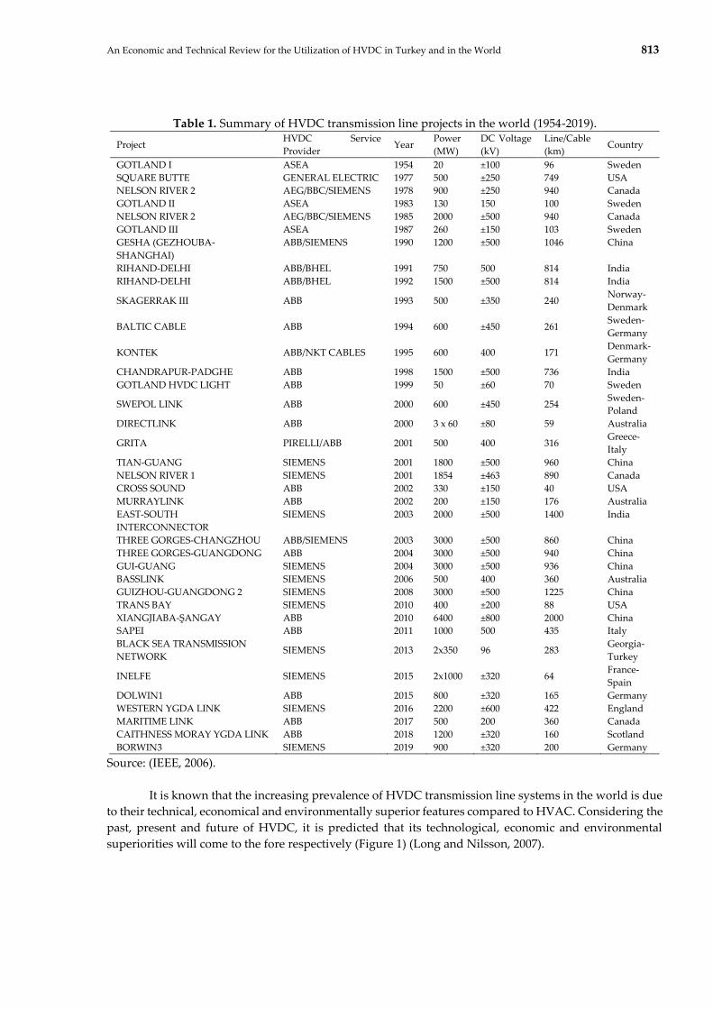
Table 1. Summary of HVDC transmission line projects in the world (1954-2019).
Project HVDC Service
Provider Year
Power
(MW)
DC Voltage
(kV)
Line/Cable
(km) Country
GOTLAND I ASEA 1954 20 ±100 96 Sweden
SQUARE BUTTE GENERAL ELECTRIC 1977 500 ±250 749 USA
NELSON RIVER 2 AEG/BBC/SIEMENS 1978 900 ±250 940 Canada
GOTLAND II ASEA 1983 130 150 100 Sweden
NELSON RIVER 2 AEG/BBC/SIEMENS 1985 2000 ±500 940 Canada
GOTLAND III ASEA 1987 260 ±150 103 Sweden
GESHA (GEZHOUBA-
SHANGHAI)
ABB/SIEMENS 1990 1200 ±500 1046 China
RIHAND-DELHI ABB/BHEL 1991 750 500 814 India
RIHAND-DELHI ABB/BHEL 1992 1500 ±500 814 India
SKAGERRAK III ABB 1993 500 ±350 240 Norway-
Denmark
BALTIC CABLE ABB 1994 600 ±450 261 Sweden-
Germany
KONTEK ABB/NKT CABLES 1995 600 400 171 Denmark-
Germany
CHANDRAPUR-PADGHE ABB 1998 1500 ±500 736 India
GOTLAND HVDC LIGHT ABB 1999 50 ±60 70 Sweden
SWEPOL LINK ABB 2000 600 ±450 254 Sweden-
Poland
DIRECTLINK ABB 2000 3 x 60 ±80 59 Australia
GRITA PIRELLI/ABB 2001 500 400 316 Greece-
Italy
TIAN-GUANG SIEMENS 2001 1800 ±500 960 China
NELSON RIVER 1 SIEMENS 2001 1854 ±463 890 Canada
CROSS SOUND ABB 2002 330 ±150 40 USA
MURRAYLINK ABB 2002 200 ±150 176 Australia
EAST-SOUTH
INTERCONNECTOR
SIEMENS 2003 2000 ±500 1400 India
THREE GORGES-CHANGZHOU ABB/SIEMENS 2003 3000 ±500 860 China
THREE GORGES-GUANGDONG ABB 2004 3000 ±500 940 China
GUI-GUANG SIEMENS 2004 3000 ±500 936 China
BASSLINK SIEMENS 2006 500 400 360 Australia
GUIZHOU-GUANGDONG 2 SIEMENS 2008 3000 ±500 1225 China
TRANS BAY SIEMENS 2010 400 ±200 88 USA
XIANGJIABA-ŞANGAY ABB 2010 6400 ±800 2000 China
SAPEI ABB 2011 1000 500 435 Italy
BLACK SEA TRANSMISSION
NETWORK SIEMENS 2013 2x350 96 283
Georgia-
Turkey
INELFE SIEMENS 2015 2x1000 ±320 64 France-
Spain
DOLWIN1 ABB 2015 800 ±320 165 Germany
WESTERN YGDA LINK SIEMENS 2016 2200 ±600 422 England
MARITIME LINK ABB 2017 500 200 360 Canada
CAITHNESS MORAY YGDA LINK ABB 2018 1200 ±320 160 Scotland
BORWIN3 SIEMENS 2019 900 ±320 200 Germany
Source: (IEEE, 2006).
It is known that the increasing prevalence of HVDC transmission line systems in the world is due
to their technical, economical and environmentally superior features compared to HVAC. Considering the
past, present and future of HVDC, it is predicted that its technological, economic and environmental
superiorities will come to the fore respectively (Figure 1) (Long and Nilsson, 2007).
Page 6
814 H. ACAROĞLU, A. NAJAFI, Ö. KARA, B. YÜRÜK
Figure 1. Vision of HVDC transmission line systems (Long and Nilsson, 2007).
Considering the area covered by the transmission lines, the area cost of the HVDC line is not as
high as that of an AC line. This also reduces the visual impact. In HVDC systems, environmental issues
such as visual impact, audible sound, electromagnetic compatibility, and the use of ground or sea return
path in mono-polar application are important for converter stations. It can be said that the HVDC system
is highly compatible with any environment and can now be integrated into the system without causing
any environmentally important issues (Bahrman, 2006).
3.1.2. The Development of HVDC Transmission Lines in Turkey
To meet the constantly growing demand for electricity in Turkey, the development of
transmission lines with technical economic and environmental advantages should accelerate. In this
context, the connection of Turkey’s electricity system to (ENTSO-E CESA) system, which is started in 2005,
in a synchronous parallel way was carried out as of April 15, 2015. With this treaty, steps have been taken
to realize synchronal connection structures with neighboring countries other than our western neighbors.
In 2016, ENTSO-E CESA observer membership agreement is signed and Turkey became the first and only
observer. 2019 is the last year for observer membership and negotiations are still ongoing. Since it is
predicted that neighboring countries such as Georgia, Iran, Iraq and Syria will not be able to meet ENTSO-
E standards in the near future, the applicability of HVDC transmission line systems with these countries
seems possible to the extent permitted by ENTSO-E standards. The existing interconnection lines in
Turkey as of 2018 is located in Figure 2 (TEİAŞ, 2016).
According to TEİAŞ data, electricity is imported by the isolated region method from Iran. The
efforts to transform this transfer to asynchronous connection with back-to-back connected HVDC system
started gradually (from 500-600MW to 1000-1200MW) as of 2016. The fact that HVDC systems allow
asynchronous structure is important in terms of facilitating the exchange of power and enabling the
expansion of the electricity trade volume between countries. In this context, for our country, Georgia
started to use the back-to-back connected HVDC system in Ahıska and enabled the transfer of electricity
into an asynchronous parallel connection. It is seen that they accelerate their work for new connections.
Apart from these developments, the interconnected project of our country with 8 countries (Egypt, Jordan,
Lebanon, Libya, Iraq, Palestine and Syria) continues (TEİAŞ, 2018).
Page 7
An Economic and Technical Review for the Utilization of HVDC in Turkey and in the World 815
Figure 2. Interconnected lines, transportation capacity, and import-export values in Turkey (TEİAŞ,
2016).
It is thought that the HVDC connections to be established with the countries especially in Figure
2 will contribute to the economy of the country by reducing the transmission losses and minimizing the
costs at the long distance. The first of the two-national level HVDC projects on the agenda is the electric
power transmission line from Akkuyu Nuclear Power Plant and the other is an HVDC transmission line
planned for Cyprus. A possible Akkuyu-Istanbul HVDC transmission line will consist of 4 units each with
1200MW power and it is expected to have 4800MW power. It is seen that HVDC systems are the most
efficient solution for transmitting to Istanbul, where demand is high. Here, thyristor based HVDC systems
or IGBT based HVDC systems are applicable. However, the technologies used here need to be analyzed
well.
Before installing the HVDC system in Turkey, it is necessary to create a road map that identifies
the possible future establishment of other HVDC system. Thus, the first project to be established needs to
be developed accordingly. Otherwise, integration of HVDC stations to be installed, later will be a problem.
When these scenarios are considered, a master plan covering all of them should be made. In line with the
plan to be created, projects should be developed step by step. It is predicted that an HVDC transmission
line between Istanbul and Akkuyu can form the backbone of such a scenario. It is thought that if every
HVDC station to be installed in the future creates a DC network integrated to its installed stations, this
will both increase the stability of the network and enable the use of energy resources more efficiently.
3.2. HVDC Transmission Line Configuration
The HVDC transmission system configuration, which is more advantageous than HVAC in terms
of cost and transmission losses, has various components. These components can be listed as follows
(Haugland, 2008):
Converter station
AC-DC filters
Smoothing Reactors
Reactive Power Source
Reactor Inverter
Page 8
816 H. ACAROĞLU, A. NAJAFI, Ö. KARA, B. YÜRÜK
Figure 3. The configuration of the HVDC transmission line (Haugland, 2008).
Direct current configuration can be generally classified as mono-polar, bi-polar and homo-polar
system as shown in Figure 4 (Haugland, 2008). In the mono-polar DC systems only one conductor (positive
or negative end) is used. This configuration is often used as the first step of the DC link until the load
requires upgrading to the bipolar link. Konti-Skan (1965) and Sardinia-Italy (1967) projects are examples
of single circuit links. In bipolar DC current systems, which are known as the most common configuration
type, two conductors (positive and negative) are used with the same voltage (Zangana and Erçelebi, 2016;
Yidong and Yu, 2013). There are sets of equal level converters in series link that increase the power
transmission capacity on the DC side of each terminal. The grounded link between the converters is at one
or both ends. Under the standard operation condition, the currents are the same in both poles and there is
no ground current (Sood, 2004; Brenna et al., 2016).
Apart from the mono-polar and bipolar system in DC configuration; homo-polar, back-to-back,
and multi-terminal system configurations are also included. In the homo-polar configuration, two
conductors with the same end (usually negative) can be operated with a ground or metallic return (Sood,
2004). Besides, the back-to-back configuration, is often used to connect the asynchronous AC system.
Inverter stations are located in the same place and no transmission line or cable is required. Argentina-
Brazil interconnection is an example of such system configuration. HVDC converter stations in a multi-
terminal configuration, are geographically separated by cables and transmission lines (Cotts, 2017). In this
configuration, converter stations are connected to the same voltage or more converter stations are
connected parallel in terms of one or both two poles in series. Sardinia-Corsica-Italy (SACOI) Pacific
Intertie and Hydro Quebec links in USA are examples for the multi-terminal HVDC systems applications
(Hausler, 1999; Kamalapur et al., 2014). HVDC transmission line link systems have advantages and
disadvantages against each other. The advantages and disadvantages of the link systems are summarized
as follows in Table 2.
Page 9
An Economic and Technical Review for the Utilization of HVDC in Turkey and in the World 817
Figure 4. Different configurations for HVDC transmission lines (Haugland, 2008).
Table 2. HVDC Advantages and disadvantages.
Advantages Disadvantages
Monopolar
System
● The corona effect is less.
● Less conductor materials are
required for using the ground as a
return path.
● Less insulation is required.
Bipolar System
● The power transition power
transition capacity is twice as the
mono-polar systems.
● When a fault is occurred in one
conductor, the half power
continues from the other
conductor.
● The terminal equipment costs are
high.
● More conductor materials are
required.
● The corona effect is much higher.
Homo-polar
System
● The corona effect is less for the
reason of negative polar
conductors.
● More less conductor materials are
required for using the ground as a
return path.
● Failures caused by malfunction can
be prevented as transmission can
be provided from other conductors.
● High reliability.
● Less investment costs.
● The ground return path causes
metallic wear.
● It causes noise in the underground
communication cables.
Source: (Haugland, 2008).
Page 10
818 H. ACAROĞLU, A. NAJAFI, Ö. KARA, B. YÜRÜK
3.2.1. Converters
The HVDC System converts the electrical current from AC to DC at the transmission end and DC
to AC at the receiving end. The important component of this system is electronic converters, which can be
classified into two main types of Line-Commutated (LCC) and voltage source converter (VSC). Possible
circuits for the HVDC converters and comparison between LCC and VSC can be found in Figure 5 and
Table 3.
LCC (line commutate converter) and VSC (voltage sourced converter) HVDC:
The figures below show the LCC (current sourced Line-commutated) and VSC (Voltage sourced
self-commutated) circuits used in HVDC transmission lines.
Figure 5: a) LCC circuit b) VSC circuit
The selection of HVDC technology type varies depending on the amount of power transmitted,
the degree of control required and the price. LCC is a mature technology used for a long time. VSC is still
in the development stage with a potential for improvement. Due to the equipment at the conversion
station VSC is more expensive. VSC conversion stations have higher losses than LCC. Mircea and Philip
(2017), by comparing the LCC and VSC conversion stations, LCC have lower losses (0.5-1%) than VSC
(1.8-3%). Technical comparison of LCC and VSC shown in Table 3:
Table 3. Technical comparison of LCC and VSC.
LCC HVDC VSC HVDC
High power capacity Low power capacity
Good overload capacity Poor overload capacity
Creates harmonic distortion
(AC and DC harmonic filter required)
Negligible harmonic generation
(No filter required)
Requires converter transformer Conventional transformer is used
Low station cost High station cost
High reliability Lower reliability due to the high number of
components
More mature technology less mature technology
Low in cost High Cost (10-15%)
Source: (Mircea and Philip, 2017).
Since there is no grounding, VSC technology is bipolar by nature. The disadvantage is that in the
event of a malfunction or during periods of maintenance, the systems must be shut down completely
without the possibility to disconnect the current from another pole and at least partially resume operation
(Table 4). It is not currently possible to talk about VSC-HVDC interconnection which is has a long distance
and a high capacity. However, this technology is thought to be able to compete with the classic HVDC in
the coming years (Mircea and Philip, 2017). The choice of DC configuration is basically affected by the
needed reliability, ratings, cost effectiveness and compliance with local policies and regulations. They are
commonly used mono-pol and bipolar connections of HVDC transmission systems. Homo-polar
Page 11
An Economic and Technical Review for the Utilization of HVDC in Turkey and in the World 819
connection types are rarely applied and mostly depend on the designs of other common. In contrast, to
connect unsynchronized AC networks back-to-back configurations is preferred. For example, the Al-
Fadhili project launched in 2009 to connect the Saudi Arabia system to neighboring markets (Kuwait,
Qatar and Bahrain) with a total capacity of 1800 MW (Macleod et al., 2010; Li et al., 2014). Projects with
current configuration data in the world reveal that 33% are structured in B2B style. In most of these B2B
connections, LCC converters are more widely used than VSC converters, as the LCC has less power loss
(Van Hertem and Ghandhari, 2010).
Table 4. The comparison of converter types.
LCC VSC
AC
The energy storage device needs
(capacitor).
The energy storage device needs
(Inductor).
Needs large AC filters. Needs small AC filters.
Reactive power supply is required for
power factor correction.
No power supply is required.
DC
Requires energy storage device (Inductor). Requires energy storage device (capacitor).
Requires DC filter. The energy storage capacitor provides DC
filtering without paying additional cost.
Provides natural fault current limiting
feature.
As the charged capacitor will work the
problematic fault is discharged in DC line
side faults.
Switching Switching takes place at the line frequency. Switching takes place at high frequency.
Source: (Sood, 2004).
The converter transformers according to the winding connections are as follows: I) single-phase,
three windings. II) three-phase, three windings. III) single-phase, two windings. IV) three-phase, rotation.
Transformer type directly affects transport size and convenience as an important selection criterion. High-
level transformers are physically huge for high- powered applications and are impractical to carry to the
field. Instead, option (III) is benefited frequently in HVDC applications since transformers are linked to
three-phase arrangements at the station and maintain acceptable phase balancing and are easier to
transport, which makes it easy to add replacement transformers on site at an acceptable cost for raised
system reliability (Bancal, 2015). The properties of the converters used in HVDC and HVAC transmission
lines are shown in Table 5 (Haugland, 2008).
Page 12
820 H. ACAROĞLU, A. NAJAFI, Ö. KARA, B. YÜRÜK
Table 5. Comparison of HVAC and HVDC transmission system converter.
HVAC HVDC LCC HVDC VSC
Maximum
usable
capacity
at 400 kV 800 MW
at 220 kV 380 MW
at 132 kV 220 MW
all up to 100 km
up to 600 MW (submarine
transmission)
Installed up to 350 MW,
800 MW is being
developed.
Voltage level
132 kV installed
220 and 400 kV are being
developed.
800 kV and above ±300 kV
Black-start
functionality
Yes No Yes
Maintenance
requirements
Low High Medium
Cable model Resistance, reactance Resistance Resistance
Installation
costs
Low for station (only
transformer)
High cost for cable
High cost for station
Low costs for cable
The station is 30-40%
more expensive than
LCC.
Equipment
costs
It is expected to be less
than 75km. Reactive
compensation and
resulting platform cost
increase for higher
distance and power.
Similar to VSC but
additional cost for reactive
compensation and less
compact, thus higher
platform costs
Recently, VSC costs have
become similar to LCC
costs. VSC is more
compact, so the platform
cost is lower.
Power loss
The losses from the cable
are directly proportional
to the distance
Approximately 3.3%
conversion losses and
cable losses proportional
to distance
Approximately 1.5%
conversion losses and
cable losses proportional
to distance
Source: (Ackerman, 2005; Raza et al., 2017).
3.2.2. Filters (AC-DC)
Related with AC and DC filters, AC filter is linked to AC side of converter transformer and DC
filter is linked to DC side in the same way. While the purpose of the use of AC filter is to prevent harmonics
and high frequency components entering the system, DC filters prevent the inference of harmonic voltages
in the transmission line where the currents overlaps and create noise (Ai and Tin, 2014). If they are not
filtered, cause capacitors and adjacent generators to overheat.
3.2.3. Converters (VSC Thyristor)
Conversion between AC-DC and DC-AC is provided by converter valves. Thyristor consist of
valve bridges and step-changing transformers. Valve bridges consist of six pulse or twelve pulse valves
depending on the arrangement. The converter transformer supplies an ungrounded 3-phase voltage
source to the value bridge. When the value samples are examined, mercury arc value, thyristor value and
VSC valve appear. In VSC value thyristor, current harmonics on the AC side are directly related to the
PMW frequency, as it must compensate for any reactive power consumed by it. Thus, it significantly
reduces the amount of filter required (Kundur, 1994; El-Saady et al., 2016).
Page 13
An Economic and Technical Review for the Utilization of HVDC in Turkey and in the World 821
3.2.4. Reactive power source
Reactive power supply, which is important for maintaining voltage balance in a large-scale
transmission system, is used to meet the reactive power requirement, develop voltage profiles and reduce
network loss. The converter stations absorb reactive power during operation. The reactive power absorbed
in the stationary operation is approximately 50% of the transmitted active power. This percentage raises
under temporary conditions and thus reactive power supplies are normally provided near transducers
(Kundur, 1994; Machado et al., 2015).
3.2.5. Electrodes
To provide a neutral connection to ground and reduce current densities, large surface conductors
are normally employed. Conductors connected in this way are called electrodes. However, it is
recommended to limit the current flow in the world, and therefore metallic return conductors are used for
this purpose (Azimoh, 2010).
3.2.6. Corrective Reactor
The smoothing reactor placed on the DC line reduces the fluctuations in the DC current and
prevents current leakage in case of failure (Gamit et al., 2015). The functions of these high inductance large
reactors can be listed as follows:
Reduce peak current of the rectifier in the DC line faults.
Prevents commutation failure.
Decreases the harmonics in DC line.
4. TECHNICAL AND ECONOMIC PERFORMANCE EVALUATION OF HVDC
HVDC transmission systems have many advantages in terms of cost and transmission losses
against HVAC systems as far as long-distance transmission line is concerned (Okba et al., 2012; Xiong et
al., 2017):
Simple and smaller transmission towers.
Narrower right of way
Requires only one-third of the isolated conductor sets as double-circuit AC lines.
Operated independently of each conductor circuit.
No charge current exists in steady state.
Less loss since there is no skin effect.
No reactive compensation required.
Distances are not limited to stability.
Short circuit current is very low.
It does not contribute to the short circuit current of an AC system.
For underground or submarine cables, there are no physical restrictions that limit the distance or
power level.
4.1. Technical Performance Assessment of HVDC
The fast-controllable structure of HVDC transmission lines provides an advantage in providing
full control over the transmitted power. The DC line connected to AC increases the transmission and
dynamic stability of the line. The angle difference between the voltage phasor at the beginning and end of
an AC line affects power transfer. As the distance increases, the increasing angle difference limits the
stability of the transient states for maximum power transmission. Power carrying capacity in line AC
Page 14
822 H. ACAROĞLU, A. NAJAFI, Ö. KARA, B. YÜRÜK
varies with inverse proportion depending on the length of the line. DC lines are capable of carrying power
regardless of the length of the line. Voltage control on the AC line is more difficult than on DC lines. The
reason for this is that reactive power is required as the load on the line increases to provide constant
voltage at the beginning and end of the line. Whereas DC lines themselves do not need reactive power
control directly (Barthold, 2006; Kharade and Savagave, 2017; The Crown Estate, 2008). For the increase in
power transfer and voltage control in long AC transmission lines, static VAR compensator (SVC) and
static compensator of the shunt reactor and serial capacitor are required, while such compensations are
not required from DC lines. High ground impedance in AC, both effects the efficiency of power transfer
and causes interference. Whereas in DC, the ground impedance can be neglected by using a single
conductor with mono-polar link system. Even when working with mono-polar link in DC transmission
line systems, the AC network feeding the DC converter station operates with balanced currents and
voltages. In this case, a single-phase system in AC cannot be implemented for more than one second,
while, long-term operation can be achieved even with a single pole in DC (Mircea and Philip, 2017).
4.1.1. Cables
When the applicability of DC lines is examined; in case of using long cable links exceeding
approximately 40-50 km break-even distance, DC cable and energy transmission system is advantageous
compared to AC cable link system. In recent years, the use of VSC and durable polymer DC cables has
become increasingly common.
Large power transmission over long distances creates an economic advantage over AC when
breakeven point is exceeded. Projects starting from the Pacific link line to China and India can be
exemplified in this sense. Due to the impact of developments in power electronics switching systems, in
the development of new compressed converters, which decreases the costs appears to have reduced the
break-even point for DC link. Load flow control of AC connections is difficult in large interconnected
connections. This difficulty is overcome thanks to the fast control power and time-dependent overload
capacities of the DC (Sood, 2004).
High-voltage AC cables have much greater shunt capacitance than overhead transmission lines
per km. For long distances, the capacitance grows and the reactive current required to charge the cable
approaches the rated current, leaving less current capacity to transmit active power, causing the cable to
decelerate. Over a certain distance, real power transmission becomes impossible. Shunt capacitance of an
AC cable must be met by distributed balancing across the cables. However, this is not possible in marine
transmission and shunt reactors or STATCOMs are used at both ends (Normark and Nielsen, 2005).
Figure 6. HVAC and HVDC cable comparison (Sood, 2004).
Page 15
An Economic and Technical Review for the Utilization of HVDC in Turkey and in the World 823
DC cables, on the other hand, do not produce or consume any reactive power and their active
power capacity almost does not damage the distance. In addition, AC cables have insulator losses and
skin effect unlike DC cables. Economically, DC cables are less costly than AC cables with the same voltage
and power rating. When using an AC cable, the change in the reactive consumption of the cable with the
transmitted power is a problem. Cable operation will be at a relatively stable operating point, if it can be
compensated before reaching a point where the transfer capacity of the cable is fully utilized (Mirebeau
and Syrtveit, 2015; Ye et al., 2018).
There are two types of cables commonly used in HVDC transmission line systems. The first one
is Mass Impregnated (MI) cables. This cable system was first used in 1954 at 100 kV HVDC project in
Gotland, Sweden (ABB, 2014). The insulation system of MI cables can be described as lapped paper tapes
impregnated with an adhesive, oily compound. This cable system can be used with both VSC and LCC
converters. Extruded HVDC cables are another type of DC cable that is more sustainable and flexible
alternative to MI cables. This type of cable was initially used in HVDC transmission line systems in 1999
(Bergelin et al., 2017). In extruded HVDC cables, the insulation material is based on cross-linked
polyethylene (XLPE). Therefore, these cables are called XLPE cables. XLPE cables are employed mainly in
VSC-HVDC links since they tend to fail because of excessive DC voltage, as opposed to power flow when
used in LCC-HVDC links. The advantages of XLPE cables compared to MI cables can be listed as follows
(Gu et al., 2018; Zeng et al., 2018) and seen in Table 6:
Easy to carry, low weight and design flexibility.
Mechanical strength.
Fast production process.
Being environmentally friendly without using recyclable materials.
Considering the advantages of XLPE cables over MI cables, it is expected that HVDC will have a
major stake in the transmission line systems market in the future.
Table 6. Comparison of XLPE and MI cable technologies.
Cable Type MI XLPE
Isolation Type Paper/Oil Polymer
First Use in HVDC 1954 1999
HVDC Application LCC/VSC VSC
Mechanical Weight/ Isolation High / Hard Low / Soft
Longest Distance 580km 400km
Maximum Power 2200MW/±600kV 2000MW/±320kV
Source: (Pipelzadeh et al., 2015; Francos et al., 2012; Murata et al., 2013; Mokhberdoran et al., 2017; Vrana
and Energi, 2016).
Figure 7 shows the specification of MI and XPLE cables that used in a HVCD line.
Page 16
824 H. ACAROĞLU, A. NAJAFI, Ö. KARA, B. YÜRÜK
(a)
(b)
Figure 7. a) MI cable. b) XPLE cable.
Insulators Used in Overhead Lines: Different types of insulators are used in overhead lines according to
the voltage value.
Pin Type Insulator: This isolator is used in transmission or distribution networks up to 33 kV. Insulator
can be one piece, two pieces or three pieces, depending on the voltage level. At voltages higher than 33
kV, it is very difficult to make a single piece of porcelain due to the increase in insulator thickness. In this
case, a multi-piece pin type insulator must be designed. Figure 8 shows the 33 kV pin type insulator.
Page 17
An Economic and Technical Review for the Utilization of HVDC in Turkey and in the World 825
Figure 8. 33 kV Pin type insulator
Post Type Insulators: Post insulators are used for higher voltages compared to pin insulators. Especially
in high or medium voltage lines, this type of insulator is highly preferred. These insulators are the group
A that specified in IEC 60383, in other words, they are puncture-proof Air Line Support Insulators. This
insulator has more combinations and is much higher. Post insulators can be mounted horizontally and
vertically on the supporting structure. Figure 9 shows the post type insulator.
Figure 9. Post type insulator
String Insulators: These types of insulators are used to fix the conductor in medium and high voltage
energy transmission and distribution lines by hanging or stretching the conductor. Insulators in the
production program are divided into groups shown below.
Normal type chain insulators with ball and socket joint
Chain insulators used in dirty areas (fog type) with ball and socket joints
These types of insulators are connected together in series to form a string and the line conductor
is carried by the lowest insulator. Because of its disc type shape, each insulator of a suspension rope is
Page 18
826 H. ACAROĞLU, A. NAJAFI, Ö. KARA, B. YÜRÜK
called a disc insulator. A very high level of mechanical strength and electrical insulation properties are
required in string insulators.
Figure 10. String type insulator
4.3. The Evaluation of Economic Performance
When HVAC and HVDC are compared economically, we encounter with three cost components:
The terminal cost
The line cost
The Losses cost
The total cost is divided into two as the cost to establish the infrastructure and the cost to run the
system when it becomes functional. It takes into account investment cost, poles, conductors and
insulations, converter stations and the right of way usage. The operating cost particularly includes losses
expressed financially.
Page 19
An Economic and Technical Review for the Utilization of HVDC in Turkey and in the World 827
Figure 11. The comparison AC and DC right of way (ROW) (Mircea and Philip, 2017).
ROW size varies between AC and DC line. In particular, this difference creates a significant
discrepancy in costs when crossing densely populated areas with high land value. Kumru and Arıkan
(2020) suggest safe ROW distances. For the same power capacity, DC ROW can be half the width of AC
(Figure 11). Assuming that the conductor and insulation types are the same for AC and DC, AC needs
three conductors for the same voltage, while DC needs two conductors (Pletka et al., 2014). Thus, DC poles
turn into a narrower passageway which requires less material for conductors and insulators (Mircea and
Philip, 2017). In addition, the fact that DC needs two conductors instead of AC needs three conductors,
indicates that DC losses are 2/3 of the AC losses. Considering the very long mileage distances, losses in
AC lines gain great importance. In Figure 12, AC and DC transmission line losses are calculated as follows
(Kalair et al., 2016; May et al., 2016):
Power transmitted by DC = 𝑉𝑑𝐼𝑑 (1)
Power transmitted by AC = 3𝑉𝑎𝐼𝑎 cos 𝜃 (2)
DC power loss = 2𝐼𝑑2R (3)
AC power loss = 3𝐼𝑎2R (4)
When the transmission losses of AC and DC in equations (3) and (4) are equalized, equation (5) is
achieved.
2𝐼𝑑2R=3𝐼𝑎
2R → 𝐼𝑎
𝐼𝑑= √
2
3 (5)
When using DC instead of three phase AC, under the assumption of the same power transmission,
the same conductor size and the same power loss;
Page 20
828 H. ACAROĞLU, A. NAJAFI, Ö. KARA, B. YÜRÜK
Figure 12. Conversion of three phase AC transmission line to DC transmission line (Kalair et al., 2016;
May et al., 2016).
In case the power transmitted on both sides is the same, the number (6) is obtained.
3𝑉𝑎𝐼𝑎 = 𝑉𝑑𝐼𝑑 → 𝑉𝑑
𝑉𝑎= 3
𝐼𝑎
𝐼𝑑= 3√
2
3= √6 (6)
Thus, the link between the AC installation level and the DC installation level is expressed in the
equation number (7).
AC Installation Level
DC Installation Level
=1
2√2
𝑉𝑑
𝑉𝑎=
√6
2√2= 0.867 (7)
When the 3-phase double circuit AC line is converted to 3-phase double circuit DC line, the
relationship between the power transmitted by DC and the power transmitted by AC is expressed as
equation (8).
3-phase double circuit AC line power transfer = 2(3𝑉𝑎𝐼𝑎 cos 𝜃)
3-phase double circuit DC line power transfer = 3𝑉𝑑𝐼𝑑
Power Transmitted by DC
Power Transmitted by AC
=3𝑉𝑑𝐼𝑑
6𝑉𝑎𝐼𝑎=
3(2√2𝑉𝑎)
6𝑉𝑎𝐼𝑎 = √2 = 1.414 (8)
It is known that the diameter of the DC conductor is also different from AC. While AC uses only
the peripheral part of the conductor, DC utilizes from the whole part of the conductor. Thus, with the
same diameter conductor, DC conducts 30-40% more electricity than AC, and it is clear that DC has
become more efficient than AC (Meah and Ula, 2006). The unit cost of electrical energy transmitted with
increased efficiency is less for DC. As seen in Figure 13, the requirement for converters and filters causes
DC systems to be more costly. Nonetheless, fewer losses in DC transmission compensate for this cost,
especially in terms of long distance (Elliott et al., 2015). In the AC and DC cost comparisons, it is seen that
the break-even distance for break-even lines is 500-800 km (tending to fall 500-600 km) and 50 km less for
submarine cables. While AC is profitable for short distances below the break-even distance, DC becomes
profitable over the break-even distance for longer distances (Hur, 2012; EEP, 2014; Eltamaly et al., 2017).
Page 21
An Economic and Technical Review for the Utilization of HVDC in Turkey and in the World 829
Figure 13. The cost comparison of HVAC and HVDC transmission systems (Elliott et al., 2015).
Since conversion stations are very costly, initial investment costs are higher for DC systems.
However, since it requires smaller number of conductors and simpler and lighter poles, DC is more
advantageous than AC in terms of the cost of the transmission line, especially in long distances (Chen et
al., 2015). In addition, the fact that DC's losses are less than AC for long distances compensates for the first
station cost that occurred at the beginning and DC appears as a less costly and efficient transmission
system over time.
4.4. A Technical Comparison and Discussions
4.4.1. A Technical Comparison: Investment Costs of the Transmission System
The investment cost of the transmission system is separated into various components for both
HVAC and VSC HVDC options which can be seen in the first column of the Table 7 (Van Eeckhout et al.,
2010). As it is seen from Table 7, the substation cost is higher for the VSC HVDC against HVAC due to the
IGBT-based DC/AC converters (phase reactors, power electronics, filters, enclosed valves, transformers,
etc.). A substation is required for both ends of the transmission cable in each technology. The price of the
bipolar HVDC cable-pair for transporting the equal amount of active-power is less than the price of the
two-parallel three-core HVAC cables. The DC cables do not require three phases in one cable, which makes
them less complex, they have lower insulation and symmetry requirements, and they need less conductor
surface of transported power per unit. The market price of cables is affected by the volatile characteristic
of the price of copper.
Table 7. A comparison for the prices of the transmission systems for 300 MW offshore wind farm in
Germany.
Item HVAC VSC HVDC
Substation (M€) 10 45
Cable (k€/km) 1500 600
Cable Installation (k€/km) 340 215
Offshore Substation Rig (M€) 13 24
Onshore Land Use (k€) 50 125
Source: (Van Eeckhout et al., 2010).
Page 22
830 H. ACAROĞLU, A. NAJAFI, Ö. KARA, B. YÜRÜK
The installation cost of DC cables is lower than the installation cost of AC cables. Moreover, their
installation is easier due to the flexibility of the cables (single core vs. three-core) and they have thinner
construction for the cable insulation. As a protection from the submarine environment both cable
technologies are buried 1 meter deep in the seabed that is a general standard for undersea transmission
protocol. The cost of substation platform which depends on the volume is assumed to be 1000 €/m3 for the
offshore rig. The installation of a DC/AC converter needs more space than an AC station, leading a higher
rig cost for the VSC-HVDC. On the other hand, the onshore land utilization is a minor transmission system
cost that depends on the type of surface (Van Eeckhout et al., 2010).
4.4.2. Discussions
Energy, an important indicator of welfare with its economic, social and environmental
dimensions, is an important production input. Rapid population growth, urbanization, industrialization
and production increase in the world are increasing the demand for energy day by day. It is very important
for each country to determine a separate domestic and foreign policy for energy production and
consumption in order to provide energy, which is in almost every area of our lives in the 21st century.
Today, the dynamic nature of international balances and the asymmetric distribution of energy resources
around the world bring with it the energy supply security problem for countries with high foreign
dependence on energy. In world economies where efforts to increase economic welfare intensify, foreign
dependence on energy is increasing in parallel with the production levels. The increase in foreign
dependency on energy affects the economy negatively through causing an increase in the current account
deficit, an important import item in the countries. For this reason, countries need to raise their current
capacity and efficiency to reduce the foreign dependency on energy and to overcome the energy supply
problem.
While developed countries often have sufficient economic power in terms of increasing existing
capacity and energy efficiency investments, this may not be possible for developing countries due to
economic difficulties. For this reason, it is thought that in developing countries obtaining high efficiency
from their existing capacities will accelerate the studies about planned capacity increase. HVDC
transmission line technologies have come to the fore in national and international connections among the
steps taken in energy efficiency in recent years. Among the steps taken in energy efficiency in recent years,
HVDC transmission line technologies in national and international connections have come into
prominence. The rapid advancement of HVDC transmission line systems in the last five decades in the
world is due to their technological and economic advantages compared to HVAC transmission line
systems. It is seen that HVDC transmission line systems provide around 40% higher efficiency than HVAC
transmission line technologies due to less cost and transmission loss. In Turkey, a developing country
with a high dependency on foreign energy, HVDC transmission line systems are predicted to have a
leading role in reducing dependency on foreign energy by ensuring energy efficiency. The agreement with
an important service provider, ENTSA-E CESA, in the market of HVDC transmission line systems in
Turkey is expected to accelerate the infrastructure operations of the HVDC transmission line systems.
Thus, within the scope of 2019-2023 energy strategies, it is expected to create opportunities in terms of
accessibility to energy at national and international level, energy efficiency and reduction of foreign
dependency on energy.
5. CONCLUSIONS
In this study, the technological and economic superiorities of HVDC transmission line systems
compared to HVAC transmission line systems and sample applications in the world are analyzed. In line
with this framework, it presents the components, market structure, current situation in the world and in
Turkey, and future trends of HVDC transmission line systems with a contemporary look. Findings
obtained by examining the literature in detail can be listed as follows: LCC converters are widely used in
HVDC transmission line systems compared to VSC converters in terms of available capacity. In cable
Page 23
An Economic and Technical Review for the Utilization of HVDC in Turkey and in the World 831
structures, XLPE cable is preferred more than MI cable. It is expected that, in HVDC transmission line
systems, MTDA connections will have a crucial role in the future with their outstanding advantages over
other connection types. When the geographical distribution of HVDC transmission line systems is
examined, it is seen that the Asian continent is in the first place. The continent of Asia is followed by
Europe, North America, South America and other continents respectively.
Although, there are studies that focus on the reduction of the size and cost of the HVAC systems
(Özcan, 2018) and model the underground high voltage cables (Akbal, 2017), the national and
international levels of HVDC transmission line system is still not a mature technology and is yet to be seen
in the development stage in Turkey. Thereby, a technical comparison example is given for investment
costs of the transmission system for 300 MW offshore wind farm in Germany. It is believed that HVDC
transmission technology and related investments and ancillary services operating with renewable energy
will be in Turkey in a close future.
The spread of HVDC transmission line systems worldwide due to low cost and high efficiency
advantages over long distances is of great importance in terms of meeting the increasing energy demand
and energy corridors that will be formed with international connections. It is thought that the
development of HVDC transmission line systems, especially in countries that import a large part of its
energy, will contribute to a reduction in imports due to increased efficiency and to decrease the import
effect on the current account deficit indirectly. It is expected that having easy access to energy through
international connections with the effect of decreasing costs and increasing efficiency will be facilitated in
favor of price fluctuations in the international energy market. Considering the mentioned advantages, it
is thought that evaluating the effect of rapidly growing HVDC transmission line systems on energy
demand in terms of cost and losses will be a solution for energy efficiency in countries with high foreign
dependency on energy, particularly in Turkey. In addition, this assessment is important in terms of
determining the opportunities of HVDC transmission line systems that are planned to be established in
the future.
REFERENCES
ABB, 2014, Review Special Report 60 Years of HVDC,
https://searchext.abb.com/library/Download.aspx?DocumentID=9AKK106103A8195&Languag
eCode=en&DocumentPartId=&Action=Launch , Access Date: 12.04.2020.
Ackerman, T., 2005, Wind Power in Power System, 2nd Ed. UK, John Wiley & Sons.
Ai, P., Tin, T., 2014, “Design Implementation of 250kV HVDC Overhead Transmission System”,
International Journal of Scientific Engineering and Technology Research, Vol.3, No.15, pp. 3223-
3227.
Akbal, B., 2017, “Forecasting Applications of the Sheath Current of High Voltage Cable with Artificial
Neural Network Based Hybrid Methods”, Pamukkale University Journal of Engineering
Sciences, Vol.23, No.2, pp. 119-125.
Alassi, A., Banales ,S., Ellabban, O., Adam, G., Maclver, C., 2019, "HVDC Transmission: Technology
Review, Market Trends and Future Outlook", Renewable and Sustainable Energy Reviews, vol.
112, pp. 530-554.
Almgren, B., Urban, A., Dong, W.,"A Survey of the Flashover Performance of HVDC Converter Station
Insulators", IEEE 1998 International Conference on Power System Technology, Beijing, China,
516-519, 18-21 Auqust 1998.
Azimoh, L.,C., 2010, Investigation Into Voltage and Angle Stability of A Hybrid HVAC-HVDC Power
Network, Master Thesis, University of Cape Town, South Africa.
Bahrman, MP., “Overview of HVDC Transmission”, 2006 IEEE PES Power Systems Conference and
Exposition, Atlanta, USA, 29 Oct-1 Nov 2006.
Bancal, S., 2015, Basic Design of An HVDC Interconnection in Brazil, Master Thesis, KTH Royal Institute
of Technology, Stockholm, Sweden.
Barthold, L.,O., “Technical and Economic Aspects of Tripole HVDC”, 2006 International Conference on
Page 24
832 H. ACAROĞLU, A. NAJAFI, Ö. KARA, B. YÜRÜK
Power System Technology, Chongqing, China, 22-26 October 2006.
Beerten, J., Gomis-Bellmunt, O., Guillaud, X., Rimez, J., Van Der Meer, A., Van Hertem, D., “Modeling and
Control of HVDC grids: A Key Challenge for the Future Power System”, IEEE 2014 Power
Systems Computation Conference, Wroclow, Poland, 18-22 Auqust 2014.
Bergelin, P., Jeroense, M., Quist, T., Rapp, H., 2017, “640 kV Extruded HVDC Cable System”. Technical
Report, NKT Group GmbH.
Bertling, L., Pramod, B., "On the Use of Reliability Test Systems: A Literature Survey", 2011 IEEE Power
and Energy Society General Meeting, Michigan, USA, 1-9, 24-28 July 2011.
Brask, M., 2008, Modelling of The Power System of Gotland Inpss/E With Focus on HVDC Light, Master
Thesis, KTH Royal Institute of Technology, Stockholm, Sweden.
Brenna M, Foiadelli F, Longo M. “Fault Detection HVDC Systems Applied to Renewable Sources”. 17th
International Conference on Electronic. Belo Horizonte, Brazil, 16-19 Oct 2016.
Burger, N., Tuson, P., 2005, “Loadflow Modelling of a 400 km 2000 MW HVDC Link", Energize, pp. 28-34.
Cao, J., Cai JY., “HVDC in China”, EPRI 2013 HVDC&FACTS Conference, Palo Alto, CA, USA, 28-29
August 2013.
Chen, G., Hao, M., Xu, Z., Vaughan, A., Cao, J., Wang, H., 2015, “Review of High Voltage Direct Current
Cables”, CSEE Journal of Power and Energy Systems, Vol.1, No.2, pp. 9-21.
Cotts, BR., Prigmore, II. JR., Graf, KL., 2017, “HVDC Transmission for Renewable Energy Integration”, in
The Power Grid, Academic Press, 171-196.
EEP, 2014, Electrical Engineering Portal, https://electrical-engineering-portal.com/analysing-the-costs-of-
high-voltage-direct-current-hvdc-transmission, Access Date: 15.03.2020.
Elliott, D., Bell, KR., Finney, S., J., Adapa, R., Brozio, C., Yu, J., Hussain, K., 2015, “A Comparison of AC
and HVDC Options for the Connection of Offshore Wind Generation in Great Britain”, IEEE
Transactions on Power Delivery, Vol.31, No.2, pp. 798-809.
El-Saady, G., Ibrahim, EA., Okilly, A., H., "Analysis and Control of HVDC Transmission Power System",
2016 Eighteenth International Middle East Power Systems Conference (MEPCON). Cairo, Egypt,
27-29 December 2016.
Eltamaly, AM., Sayed, Y., Elghaffar, ANA., 2017, "A Survey: HVDC System Operation and Fault Analysis",
Annals of the Faculty of Engineering Hunedoara-International Journal of Engineering, Vol. 15,
No.4, pp. 25-30.
Figueroa-Acevedo, AL., Czahor, M., Jahn, DE., 2015, “A Comparison of the Technological, Economic,
Public Policy, and Environmental Factors of HVDC and HVAC Interregional
Transmission”, AIMS Energy, Vol. 3, No. 1, pp. 1-18.
Francos, PL., Verdugo, SS., Álvarez, HF., Guyomarch, S., Loncle, J., “INELFE — Europe's First Integrated
Onshore HVDC Interconnection”, 2012 IEEE Power and Energy Society General Meeting, San
Diego, California, 23-26 July 2012.
Gamit, P., Shah, N., Wani ,U., Patel, P., Mali, U., Chaudhari, A., 2015, "Comparative Analysis of HVDC
and EHVAC", International Research Journal of Engineering and Technology (IRJET), Vol. 2, No.
9, pp. 1165-1171.
Giraneza, M., 2013, High Voltage Direct Current (HVDC) in Applications for Distributed Independent
Power Providers (IPP), Master Thesis, Cape Peninsula University of Technology, Cape Town,
South Africa.
Gu, X., He, S., Xu, Y., Yan, Y., Hou, S., Fu, M., 2018, “Partial Discharge Detection on 320 kV VSCHVDC
XLPE Cable with Artificial Defects Under DC Voltage”, IEEE Trans Dielectr Electr Insul, Vol.25,
No. 3, pp. 939–946.
Haugland, P., 2008, “It’s Time to Connect: Technical Description of HVDC Light® Technology”, ABB
Techincal Report, Ludvika, Sweden.
Hausler, M., “Multiterminal HVDC for High Power Transmission in Europe”, CEPEX99 Conference,
Poznan, Poland, March 1999.
Hur, D., 2012, “Economic Considerations Underlying the Adoption of HVDC and HVAC for the
Page 25
An Economic and Technical Review for the Utilization of HVDC in Turkey and in the World 833
Connection of an Offshore Wind Farm in Korea”, Journal of Electrical Engineering &
Technology, Vol.7, No.2, pp. 157-162.
IEEE, 2006, DC and Flexible AC Transmission Subcommittee of the IEEE Transmission and Distribution
Committee by the Working Group on HVDC and FACTS Bibliography and Records,
http://www.ece.uidaho.edu/hvdcfacts/Projects/HVDCProjectsListingDec2006.pdf Access Date:
15.04.2020.
Kalair, A., Abas, N., Khan, N., 2016, “Comparative Study of HVAC and HVDC Transmission Systems”,
Renewable and Sustainable Energy Reviews, Vol.59, pp. 1653-1675.
Kamalapur, GD., Sheelavant, VR., Pujar, A., Baksi, S., Patil, A., 2014, "HVDC Transmission in India", IEEE
Potentials, Vol.33, No.1, pp. 22-27.
Kharade, JM., Savagave, DNG., 2017, "A Review of HVDC Converter Topologies", International Journal
of Innovative Research in Science, Engineering and Technology , Vol. 6, No.2, pp. 1822-1830.
Kotb, O., 2018, On Stability Enhancement in AC/DC Power Systems through Multi-Terminal HVDC
Controllers, Doctoral Thesis, KTH Royal Institute of Technology, Stockholm, Sweden.
Kumru, CF., Arıkan, O., 2020, “Investigation of Line Displacement in Terms of Electrical Field Distribution
and Safe Right of Way Distance in Energy Transmission Systems”, Pamukkale University
Journal of Engineering Sciences, Vol.26, No.2, pp. 279-285.
Kundur, P., 1994, Power System Stability and Control, McGraw-Hill.
L'Abbate, A., Careri, F., Calisti, R., Rossi, S., Fulli, G., “Long-term HVDC Developments in the European
Power System: The Baltic Case in GridTech Analysis”, 2015 IEEE 5th International Conference
on Power Engineering, Energy and Electrical Drives (POWERENG), Riga, Latvia, 11-13 May
2015.
Li, W., Shi, L., Yao, L., Zhao, Y., Jian, Z., Ni, Y., “Comparison of HVAC and HVDC Based Grid Integration
on Wind Farm”, 2014 International Conference on Power System Technology, Chengdu, China,
20-22 October 2014.
Liu Z., 2014, Ultra-High Voltage AC/DC Grids, 1st ed., Waltham, USA, Academic Press.
Liu, Z., Zhang, F., Yu, J., Gao, K., Ma, W., 2018, “Research on Key Technologies in±1100 kV Ultra-High
Voltage DC Transmission”, High Voltage, Vol. 3, No.4, pp. 279–88.
Long, W., Nilsson, S., 2007, "HVDC Transmission: Yesterday and Today", IEEE Power and Energy
Magazine, vol. 5, No. 2, pp. 22-31.
Machado, J., Neves, MV., Santos, PJ., "Economic Limitations of the HVAC Transmission System When
Applied to Offshore Wind Farms", 2015 9th International Conference on Compatibility and
Power Electronics (CPE), Lisbon, Portugal, 24-26 June 2015.
MacLeod, NM., Barker, CD., Kirby, NM., “Connection of Renewable Energy Sources through Grid
Constraint Points Using HVDC Power Transmission Systems”, IEEE PES T&D 2010, Sao Paulo,
Brazil, 8-10 Nov 2010.
May, TW., Yeap, YM., Ukil, A., "Comparative Evaluation of Power Loss in HVAC and HVDC
Transmission Systems", 2016 IEEE Region 10 Conference (TENCON), Singapore, 22-25
November 2016.
Mazzanti, G., Marzinotto, M., 2013, Extruded Cables for High-Voltage Direct-Current Transmission:
Advances in Research and Development, Hoboken, New Jersey, JohnWiley & Sons, Inc.
Meah, K., Ula, S., 2006, “Comparative Evaluation of HVDC and HVAC Transmission Systems”, IEEE
Power and Energy Magazine, Vol. 4, No.6, pp. 1-5.
Mircea, A., Philip, M., 2017, “A China-EU Electricity Transmission Link”, Assessment of Potential
Connecting Countries and Routes, EUR 29098 EN, Publications Office of the European Union,
Luxembourg.
Mirebeau, P., Syrtveit, V., "Review of HVDC Insulated Transmission Cables Technologies", Jicable 2015,
9th International Conference on Insulated Power Cables, Versailles, France, 21-26 June 2015.
Mokhberdoran, A., Carvalho, A., Silva, N., Leite, H., Carrapatoso, A., 2017, “Application Study of
Superconducting Fault Current Limiters in Meshed HVDC Grids Protected by Fast Protection
Page 26
834 H. ACAROĞLU, A. NAJAFI, Ö. KARA, B. YÜRÜK
Relays”, Electric Power Systems Research, Vol. 143, pp. 292-302.
Murata, Y., Sakamaki, M., Abe, K., Inoue, Y., Mashi, S., Kashiyama, S., Katakai, S., 2013, “Development of
High Voltage DC-XLPE Cable System”, SEI Tech. Rev, Vol, 76, No. 1, pp. 55-62.
Normark, B., Nielsen, EK., “Advanced Power Electronics for Cable Connection of Offshore Wind”,
Offshore Wind Conference, Copenhagen, Denmark. 26-28 October 2005.
Okba, MH., Saied, MH., Mostafa, MZ., Abdel-Moneim, TM., “High Voltage Direct Current Transmission-
A Review”, Part I, in Proc. EnergyTech., IEEE, Cleveland, OH, U.S. 29-31 May 2012.
Özcan, H., 2018, “Thermodynamic Analysis of an Ice Slurry Thermal Energy Storage System for Decreased
Size and Cost of HVAC Systems”, Pamukkale University Journal of Engineering Sciences, Vol.
24, No.1, pp. 25-29.
Pipelzadeh, Y., Chaudhuri, B., Green, TC., Adapa, R., “Role of Western HVDC Link in Stability of Future
Great Britain (GB) Transmission System”, 2015 IEEE Power & Energy Society General Meeting,
Colorado, 26-30 July 2015.
Pletka, R., Khangura, J., Rawlins, A., Waldren, E., Wilson, D., “Capital Costs for Transmission and
Substations: Updated Recommendations for WECC Transmission Expansion Planning”,
Western Elect. Coordinating Council, Black and Veatch Project, Overland Park, KS, USA, Tech.
Rep. Project 181374, 2014.
Pudney, D., 2012, “A Review of HVDC in China”, Energize, Vol.54, pp. 31-4.
Raza, A., Shakeel, A., Tahzeeb, H., Hassan, M., 2017, “Economic Analysis for HVDC Transmission System
in Pakistan”, International Journal of Control and Automation, Vol.10, No.11, pp. 29-38.
Rudervall, R., Charpentier, J. P., Sharma, R., "High Voltage Direct Current (HVDC) Transmission Systems
Technology Review Paper", Presented at Energy Week 2000, Washington, D.C, USA, 1-17, 7-8
March 2000.
Shuai, J., 2012, Placing of VSC-HVDC Lines in a Meshed AC-Network, Master Thesis, Swiss Federal
Institute of Technology, Zürich, Switzerland.
Sood, VK., 2004, HVDC and FACTS Controllers: Applications of Static Converters in Power Systems,
Boston, USA, Kluwer Academic Publishers.
Stenberg, N., 2013, The Impact of HVDC Innovations on The Power Industry, Master Thesis, Royal
Institute of Technology, Stockholm, Sweden.
TEİAŞ, Türkiye Elektrik İletim A.Ş. 2016 Faaliyet Raporu, https://www.teias.gov.tr/tr-TR/faaliyet-
raporlari Access Date: 15.03.2020.
TEİAŞ, Türkiye Elektrik İletim A.Ş. 2018 Faaliyet Raporu, https://www.teias.gov.tr/tr-TR/faaliyet-
raporlari Access Date: 15.03.2020.
The Crown Estate, East Coast Transmission Network Technical Feasibility Study (2008),
https://archive.uea.ac.uk/~e680/energy/energy_links/transmission/east_coast_transmission_net
work_technical_feasibility_study.pdf , Access Date: 25.03.2020.
Tiku, D., 2014, “DC Power Transmission: Mercury-Arc to Thyristor YGDA Valves [History]”, IEEE Power
Energy Magazine, Vol.12, No.6, pp. 76–96.
Träff , V., Lennerhag, O., 2013, Modelling of VSC-HVDC for Slow Dynamic Studies, Master Thesis,
Chalmers University of Technology, Gothenburg, Sweden.
Ukil, A., 2015, "Theoretical Analysis of Tuned HVAC Line for Low Loss Long Distance Bulk Power
Transmission", International Journal of Electrical Power & Energy Systems, Vol.73, pp. 433-437.
Van Eeckhout, B., Van Hertem, D., Reza, M., Srivastava, K., Belmans, R. 2010. “Economic Comparison of
VSC HVDC and HVAC as Transmission System for a 300 MW Offshore Wind Farm”, European
Transactions on Electrical Power, Vol.20, No.5, pp. 661-671.
Van Hertem, D., Ghandhari, M., 2010, “Multi-terminal VSC HVDC for the European Supergrid:
Obstacles”, Renewable and Sustainable Energy Reviews, Vol.14, No. 9, pp. 3156–3163.
Vrana, TK., Energi, S., “Review of HVDC Component Ratings: XLPE Cables and VSC Converters”, 2016
IEEE International Energy Conference (ENERGYCON), Leuven, Belgium. 4-8 April 2016.
Xiong, J., Guo, J., Liu, Q., "The Application of HVDC Transmission in Shore Power Supply", 2017
Page 27
An Economic and Technical Review for the Utilization of HVDC in Turkey and in the World 835
International Conference on Industrial Informatics-Computing Technology, Intelligent
Technology, Industrial Information Integration (ICIICII), Wuhan, China, 2-3 December 2017.
Ye, H., Fechner, T., Lei, X., Luo, Y., Zhou, M., Han, Z., Li, D., 2018, "Review on HVDC Cable
Terminations", High Voltage, Vol.3, No.2, pp. 79-89.
Yidong, H., Yu, T., 2013, “Reliability Improvement Strategies for HVDC Transmission System”, Energy
and Power Engineering, Vol.5, No.3B, pp. 52-56.
Zangana, S., Ercelebi, E., 2016, “Enhance Power Quality by HVDC System, Comparison Technique
between HVDC and HVAC Transmission Systems”, World Academy of Science, Engineering
and Technology International Journal of Electrical, Computer, Energetic, Electronic and
Communication Engineering, Vol.10, No. 2, pp. 271-279.
Zeng, H., Gao, K., Zhu, Z., Li, D., Yang, R., Yang, L., "Research on Difference between HVDC and HVAC
Cable Shielding Materials", 2018 Condition Monitoring and Diagnosis (CMD), IEEE, Perth,
Australia, 23-26 September 2018.