The 6th Saudi Engineering Conference, KFUPM, Dhahran, December 2002 Vol. 4. 337 AN EFFICIENT ENERGY RECOVERY PROSPECT IN SWRO PROCESS A.T.M. Jamaluddin 1 , Ata M Hassan 2 , Ali R. Al-Reweli 3 , Abdullah Al-Rubaian 4 and Leif J Hauge 5 1: Senior Process Engineer, SWRO Dept, R&DC, SWCC 2: Senior Researcher, SWRO Dept., R&DC, SWCC 3: Senior Chemical Engineer, SWRO Dept., R&DC, SWCC 4: Technical Advisor, R&D Dept., SWCC 5: President, Hauge Technologies Inc, USA 1-4: E mail: [email protected]and 5: [email protected]ABSTRACT Consumption of energy has a vital impact on potable water production cost by seawater reverse osmosis (SWRO) desalination process. At the international cost of energy, it forms about 50-60% of the total water production cost. Operation of high pressure feed pump (HPP) requires about 70% of total SWRO processing energy of which above 66% remain in the brine (at recovery 32%, feed pressure 60 bar, ∆P 2 bar) that is rejected with a great loss in the process energy. If this reject energy is fully recovered, a saving of about 33-40% in water production cost can be achieved. For this reason, efforts have been continuing since initial commercialization of SWRO process to recover wasted energy from brine. This has led to the adaptation and modification of different pumping and hydropower generating equipment. Although, various energy recovery devices have come in practical use demand for more efficient ones continue. A maximum energy recovery output range of 30-35% was visualized by an energy recovery turbine system at lower flow. Almost the same range of recovery was achieved by some of the SWCC SWRO plants using conventional recovery system. Actually, an energy recovery system that can recover about 90-95% of the energy from the discarded brine should contribute significantly to the cost reduction of water production and for the improvement of the desalination process. The pressure exchanger (PX) system, a recently introduced energy recovery device, is claimed to have about 95% efficiency in the recovery of energy from brine, which otherwise goes to waste. An evaluation study to verify the claim practically on this system has been ongoing at the Research and Development Center (R&DC) pilot plant, Saline Water Conversion Corporation (SWCC). Initial results obtained are very encouraging. A recovery of about 93% otherwise wasted energy has been achieved. It results in a saving of about 58% energy usage to run HPP with a remarkable reduction in consumption of energy for unit water production to 2.37 kWh/m 3 , as compared to 6.2 kWh/m 3 when the unit is operated at an applied feed pressure of 60 bar and a water recovery of 32%, without using energy recovery system. Initial calculation has shown that if this system is applied in a large commercial SWRO plant (30 MIGD) a saving of about SR 12-14 million (based on energy cost) can be attained annually. The paper discusses the prospects of this system in the light of the initial results obtained so far. Keywords: SWRO, energy recovery, optimal operation, P&I and pressure energy.
Transcript
The 6th Saudi Engineering Conference, KFUPM, Dhahran, December 2002 Vol. 4. 337
AN EFFICIENT ENERGY RECOVERY PROSPECT IN SWRO PROCESS
A.T.M. Jamaluddin1, Ata M Hassan2, Ali R. Al-Reweli3, Abdullah Al-Rubaian4
and Leif J Hauge5
1: Senior Process Engineer, SWRO Dept, R&DC, SWCC 2: Senior Researcher, SWRO Dept., R&DC, SWCC 3: Senior Chemical Engineer, SWRO Dept., R&DC, SWCC 4: Technical Advisor, R&D Dept., SWCC 5: President, Hauge Technologies Inc, USA 1-4: E mail: [email protected] and 5: [email protected]
ABSTRACT
Consumption of energy has a vital impact on potable water production cost by seawater reverse osmosis (SWRO) desalination process. At the international cost of energy, it forms about 50-60% of the total water production cost. Operation of high pressure feed pump (HPP) requires about 70% of total SWRO processing energy of which above 66% remain in the brine (at recovery 32%, feed pressure 60 bar, ∆P 2 bar) that is rejected with a great loss in the process energy. If this reject energy is fully recovered, a saving of about 33-40% in water production cost can be achieved. For this reason, efforts have been continuing since initial commercialization of SWRO process to recover wasted energy from brine. This has led to the adaptation and modification of different pumping and hydropower generating equipment. Although, various energy recovery devices have come in practical use demand for more efficient ones continue. A maximum energy recovery output range of 30-35% was visualized by an energy recovery turbine system at lower flow. Almost the same range of recovery was achieved by some of the SWCC SWRO plants using conventional recovery system. Actually, an energy recovery system that can recover about 90-95% of the energy from the discarded brine should contribute significantly to the cost reduction of water production and for the improvement of the desalination process. The pressure exchanger (PX) system, a recently introduced energy recovery device, is claimed to have about 95% efficiency in the recovery of energy from brine, which otherwise goes to waste. An evaluation study to verify the claim practically on this system has been ongoing at the Research and Development Center (R&DC) pilot plant, Saline Water Conversion Corporation (SWCC). Initial results obtained are very encouraging. A recovery of about 93% otherwise wasted energy has been achieved. It results in a saving of about 58% energy usage to run HPP with a remarkable reduction in consumption of energy for unit water production to 2.37 kWh/m3, as compared to 6.2 kWh/m3 when the unit is operated at an applied feed pressure of 60 bar and a water recovery of 32%, without using energy recovery system. Initial calculation has shown that if this system is applied in a large commercial SWRO plant (30 MIGD) a saving of about SR 12-14 million (based on energy cost) can be attained annually. The paper discusses the prospects of this system in the light of the initial results obtained so far.
Keywords: SWRO, energy recovery, optimal operation, P&I and pressure energy.
Vol. 4. 338 A.T.M. Jamaluddin, Ata M. Hassan, Ali R. Al-Reweli, Abdullah Al-Rubaian, and Leif J Hauge
الملخص
حيث . تشكل تكلفة استهالك الطاقة أحد العوامل المؤثرة في التكلفة الكلية لتحلية مياه البحر بطريقة التناضح العكسي
من % ٧٠يتم استهالك . من إجمالي تكلفة إنتاج المياه المحالة وذلك حسب األسعار العالمية% ٦٠ – ٥٠تتراوح ما بين
العكسي لتشغيل مضخات التغذية ذات الضغط العالي، وتحتفظ مياه الرجيع بـ الطاقة المستخدمة في محطات التناضح
فرق ضغط عبر بار، ٦٠مياه منتجة من مياه التغذية، ضغط تغذية % ٣٢بمعدل استرداد (من هذه الطاقة % ٦٦
. التناضح العكسيمن التكلفة الكلية للمياه المحالة ب% ٤٠–٣٣وتشكل الطاقة المهدرة مع الرجيع نسبة ). بار٢ األغشية
لذلك ومنذ بداية اإلنتاج التجاري للمياه المحالة عن طريق التناضح العكسي تواصلت الجهود السترداد الطاقة المهدرة مع
وبالرغم من وجود العديد من , مياه الرجيع وأدخلت العديد من التحسينات على مضخات المياه ووسائل استرداد الطاقة
باستخدام توربينات استرداد الطاقة في معدل . د مازالت مستمرة الستحداث وسائل أكثر كفاءةهذه الوسائل إال أن الجهو
حيث تم التوصل لهذا المعدل , %٣٥ – ٣٠سريان منخفض تم التوصل إلى معدل استرداد أقصى للطاقة يتراوح ما بين
الشك أن نظام استرداد . سترداد تقليديةفي بعض محطات التناضح العكسي التابعة للمؤسسة العامة لتحلية المياه بطرق ا
من الطاقة المهدرة مع مياه الرجيع سيخفض تكلفة اإلنتاج ويسهم في تطور % ٩٥ – ٩٠الطاقة الذي يمكنه استرجاع
، وهو أحد الوسائل المستحدثة السترداد )Pressure Exchanger(ذكر مستحدثي نظام تبادل الضغط . عمليات التحلية
يقوم مركز األبحاث %. ٩٥ام يستطيع استرداد الطاقة المتواجدة في مياه الرجيع بكفاءة تصل إلى الطاقة، أن النظ
وتبدو النتائج األولية للدراسة مشجعة . والتطوير التابع للمؤسسة العامة لتحلية المياه المالحة بدارسة تقييم هذا النظام
نتيجة لذلك انخفض استهالك الطاقة المستخدمة في مضخات من الطاقة المهدرة، و% ٩٣إذ بلغت نسبة االسترداد للغاية
، وبالتالي انخفضت كمية الطاقة المطلوبة إلنتاج وحدة من المياه المحالة إلي %٥٨التغذية ذات الضغط العالي بنسبة
داد بار ونسبة استر٦٠ عند تشغيل الوحدة تحت ضغط ٣م/ كيلووات ساعة٦,٢ بالمقارنة مع٣م/ كيلووات ساعة٢,٣٧
مليون ١٤-١٢وتشير النتائج األولية أن النظام يحقق وفر يقدر بـ . بدون استخدام أي من أنظمة استرداد الطاقة% ٣٢
تتناول الورقة آفاق زيادة كفاءة ). مليون جالون يوميا٣٠(ريال سعودي سنويا عند استخدامه في محطة تحلية سعة
). Pressure Exchanger(ولية لدراسة نظام تبادل الضغط عمليات استرداد الطاقة، بناًء على النتائج األ
1. INTRODUCTION
Based on basic working principles, various energy recovery devices (ERD) that have been applied in the recovery of energy from SWRO reject, which otherwise goes to waste, can be categorized into three groups. Group 1 is based on centrifugal principle and is commonly referred to as turbo chargers. In this device reject pressure energy is converted into shaft energy (mechanical energy), which is then transferred back to feed stream as pressure energy. Two stages of energy transformation and consequently efficiency penalties are involved in the mechanism. Pump Engineering’s TURBO and FEDCO’s Hydraulic Pressure Booster are commercial examples of such systems. The device is an stand-alone package generally used for high pressure boosting in SWRO system. Group II ERD is similar to Group 1 in that the centrifugal force converts the hydraulic energy exist in the reject stream into rotational energy (mechanical shaft energy), which is then transferred back to the feed stream through high pressure pump (HPP) shaft. Unlike Group 1 ERD, Group II is an add-on package. The stages of losses in energy eficiencies are similar to Group 1. Pelton Wheels and Francis Turbines are
An Efficient Energy Recovery Prospect in SWRO Process Vol. 4. 339
commercial examples of these devices. Group III uses the principle of positive displacement and is commonly referred to as pressure exchangers. In this system pressure energy from reject is directly transferred to the feed stream without any intermediate transformation. Commercial examples of such systems are Energy Recovery, Inc.’s (ERI) Pressure Exchanger (PX), Desalco’s Work Exchanger Energy Recovery (DWEER) system, Siemag’s system and RO Kinetic’s System. The history of development and commercial application of these ERDs starts from the Francis turbines and an early Pelton wheel and passing through the Turbos and more advanced Pelton wheels has finally reached the recently introduced positive displacement one belonging to Group III. Over the last two decades, many have tried to develop devices which permits transfer of energy from one stream to another in a closed chamber by positive displacement mechanism. The successful trial in 1992 with a spin ducted rotor made from engineering ceramics, spinned at 1500 rpm, and transferred energy directly from the brine to the seawater feed without any double-dipping of energy was a breakthrough. This success lead to the recent proliferation of commercially available ERD based on the positive displacement direct pressure exchange approach. This increased interest is due to the fact that this technology can reduce the energy consumption of a SWRO system significantly.
The PX, one of the member of Group III ERD, is reported [P. Geisler, et. al.,1995; S.A. Shumway, 1999] to be successfully used for several years, in recovering energy from SWRO reject in Cayman Island (2.64 kWh/m3) and Virgin Islands SWRO plants. ERI’s PX units have also been installed to obtain major power savings in many other existing SWRO installations such as Dhekelia (Cyprus), Ghar Lapsi (Malta), Mazarron (Spain), and Vivendi (St. Maarten, Curacao, Antigua and Bonnaire) [ERI, Client List, 2000-2001]. The system is being included in design of many new large SWRO plants. The overall energy transfer efficiency of this new system is assessed to be high, and ranged between 85 to 96% or better [P. Geisler, et. al.,1995; S.A. Shumway, 1999; ERI, Client List, 2000-2001; G.G. Pique, 2000; ERI, 2001; John P. MacHharg, and G.G. Pique, 2001; Antoine Riolo, 2001]. A reduction in HPP energy consumption from 8 to 2.8 kWh/m3 [P. Geisler, et. al.,1995; S.A. Shumway, 1999] or even lower (2.0 kWh/m3) [G.G. Pique, 2000] has also been reported.
An evaluation of the PX system has been on-going at SWCC R&DC SWRO pilot plant utilizing Hollow Fine Fiber (HFF) membrane and showed very encouraging results. This paper presents and discusses the results obtained so far. Hauge Technologies Inc. (HTI) of USA is a research partner of this SWCC/HTI joint research program.
2. DESCRIPTION AND PRINCIPLE OF OPERATION OF PX
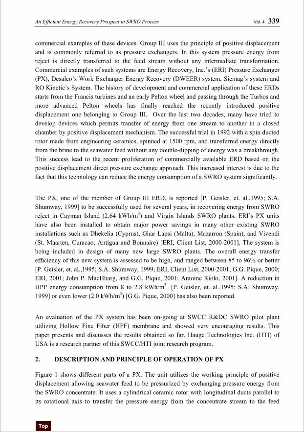
Figure 1 shows different parts of a PX. The unit utilizes the working principle of positive displacement allowing seawater feed to be pressurized by exchanging pressure energy from the SWRO concentrate. It uses a cylindrical ceramic rotor with longitudinal ducts parallel to its rotational axis to transfer the pressure energy from the concentrate stream to the feed
Vol. 4. 340 A.T.M. Jamaluddin, Ata M. Hassan, Ali R. Al-Reweli, Abdullah Al-Rubaian, and Leif J Hauge
stream. The rotor spins at about 1500 rpm inside a sleeve between two end covers with port openings for low and high pressure. About 50% of the rotor duct volume is used as a buffer or dead volume accepting direct contact of seawater at one end and concentrate at the other end. The buffer acting as a liquid piston basically never leaves the rotor duct, but moves back and forth as a floating piston for every revolution of the rotor. The low-pressure side of the rotor fills with seawater while the high-pressure side discharges seawater. The rotation of the rotor simply facilitates the valving mechanism to transport the ducts from one side to the other. At about 1500 rpm of the rotor, one revolution is completed at every 1/25 second. This will introduce a marginal intermixing less than 3-4%, which may increase feed salinity slightly, about 1%. The losses encountered in the energy transfer are flow resistance and internal leakage. Notable features of the PX are (1) it pressurizes a portion of the feed flow, nearly equal in volume and pressure to the reject stream, which is then boosted by a booster pump to near the feed pressure, and (2) it allows the feed and concentrate to have direct contact thereby eliminating the need for a piston and associated controls required to control piston movement. This way PX allows down sizing of the HPP to handle a flow equal to permeate output plus leakage loses in the PX resulting in an energy as well as capital saving. The booster pump makes up the pressure losses through the RO membranes, the PX unit and piping losses.
An Efficient Energy Recovery Prospect in SWRO Process Vol. 4. 341
3. EXPERIMENTAL SET-UP
3.1. System Preparation
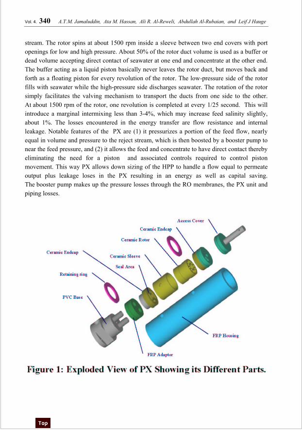
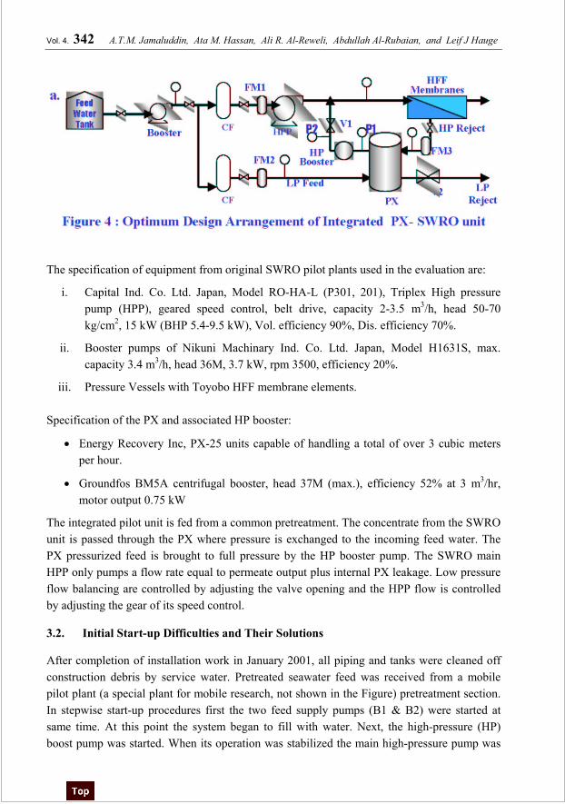
The two of the RDC SWRO pilot plants were integrated into one unit to introduce the PX into the system for its evaluation. Figure 2(a) & (b) are the two existing SWRO pilot units: Unit (a) is meant for evaluation of HFF membranes, while unit (b) for evaluation of spiral wound membranes. Other than membrane and pressure vessels (PV), technical specification and components features are similar for both the units. Figure 3 shows the modified and integrated SWRO arrangement of units 2(a) & (b) with PX introduced in it. As shown in Figure 3, one flow meter (FM3), two valves (V1 & V2), two pressure gauges (P1 & P2) and one HP booster are introduced in the system interconnections. Only one feed booster and cartridge filter of unit 2(b) are used in the integrated unit. The HPP including PV and membranes of unit 2(b) are removed. In the integrated system, feed boosters (B1 & B2) and tanks (T1 & T2) from both the units act as a single booster and tank, respectively. For this operation, feed tanks (T1 & T2) are interconnected and the pumps are arranged to start and stop at same time. This way the integrated unit can be represented as in Fig. 4, the optimum design of the system.
Vol. 4. 342 A.T.M. Jamaluddin, Ata M. Hassan, Ali R. Al-Reweli, Abdullah Al-Rubaian, and Leif J Hauge
The specification of equipment from original SWRO pilot plants used in the evaluation are:
i. Capital Ind. Co. Ltd. Japan, Model RO-HA-L (P301, 201), Triplex High pressure pump (HPP), geared speed control, belt drive, capacity 2-3.5 m3/h, head 50-70 kg/cm2, 15 kW (BHP 5.4-9.5 kW), Vol. efficiency 90%, Dis. efficiency 70%.
ii. Booster pumps of Nikuni Machinary Ind. Co. Ltd. Japan, Model H1631S, max. capacity 3.4 m3/h, head 36M, 3.7 kW, rpm 3500, efficiency 20%.
iii. Pressure Vessels with Toyobo HFF membrane elements.
Specification of the PX and associated HP booster:
• Energy Recovery Inc, PX-25 units capable of handling a total of over 3 cubic meters per hour.
• Groundfos BM5A centrifugal booster, head 37M (max.), efficiency 52% at 3 m3/hr, motor output 0.75 kW
The integrated pilot unit is fed from a common pretreatment. The concentrate from the SWRO unit is passed through the PX where pressure is exchanged to the incoming feed water. The PX pressurized feed is brought to full pressure by the HP booster pump. The SWRO main HPP only pumps a flow rate equal to permeate output plus internal PX leakage. Low pressure flow balancing are controlled by adjusting the valve opening and the HPP flow is controlled by adjusting the gear of its speed control.
3.2. Initial Start-up Difficulties and Their Solutions
After completion of installation work in January 2001, all piping and tanks were cleaned off construction debris by service water. Pretreated seawater feed was received from a mobile pilot plant (a special plant for mobile research, not shown in the Figure) pretreatment section. In stepwise start-up procedures first the two feed supply pumps (B1 & B2) were started at same time. At this point the system began to fill with water. Next, the high-pressure (HP) boost pump was started. When its operation was stabilized the main high-pressure pump was
An Efficient Energy Recovery Prospect in SWRO Process Vol. 4. 343
put on. Its capacity is controlled by speed gear set adjustment to maintain required flow. It took about 15-20 seconds to pressurize the system by main HPP operation. After one hour normal operation at adjusted flows and recoveries a leakage was observed from the bottom of the PX resulting feed pressure reduction and mixing of feed with reject. Several attempts such as pressure and/or flow regulation, joint tightening, glue application etc. to stop or reduce leakage were made but none of them were successful. Finally the PX unit was dismantled to find out the root cause/causes of the leak. Cracks on feed and reject separation wall of PVC base part, which assisted in mixing of feed with the reject at high pressure (60 kg/cm2) were detected. To solve the problem, a similar PVC part was fabricated at RDC pilot plant workshop. Replacing the defective base part with the fabricated one, the PX unit was reassembled and the SWRO unit was restarted. The reason of the cracks was due to miss matching (construction defect) of component interfaces resulted from internal tie rod head, which gave abnormal thrust on the base part at high pressure and propagated the crack with time (1-2 hour). Except this initial difficulty, the unit has been running for the last 4 months smoothly without any further maintenance. This experience leads to the idea of fabricating other parts of PX locally, except the ceramic rotor, in case of any such emergency.
3.3. Adjustment and Control of PX Operation Parameters
In order to control the high-pressure reject and feed flow rates, adjustment of the pressure and flow supplied by the HP booster pump is required. Generally HP booster with some additional capacity, instrumented by a variable frequency driver (VFD) to control its flow and pressure is the appropriate choice. Alternatively, a control valve same as V1 in Figure 3 can do the job if pump head is higher. A high-pressure flow meter (FM3) is essential to determine the amount of reject and feed water flows through the high-pressure side of the PX. Accurate pressure readings across the PX and HP booster are also essential. It could have dual applications: pressure reading and verification of flows from differential pressures. Adjustment of the flow rates & pressure, controls the percent recovery of water production and ultimately the energy.
The flow rates of low-pressure (LP) feed and reject is controlled by adjusting the LP seawater booster (B2) discharge throttling valve or by adjusting the LP reject drain valve V2. The LP seawater flow rate is determined by flow meter FM2 at the LP seawater inlet of the PX and the reject flow rate is measured manually.
A reject by-pass valve operation during start-up and shut down is found very effective in providing LP piping safety, operational benefits and simplicity. This will allow the operator to control system pressure gradually and release system pressure at shutdown.
The following approximate flow equations are applied to balance the PX in and out flows.
Vol. 4. 344 A.T.M. Jamaluddin, Ata M. Hassan, Ali R. Al-Reweli, Abdullah Al-Rubaian, and Leif J Hauge
HP seawater outlet flow = Reject flow (say, F1=F5).
If F2<F1, excessive intermixing of reject with the feed will occur. This will result with low quality permeate, increased feed pressure and higher energy consumption.
If F2>F1, pretreated feed water is being wasted and dumped to the LP reject drain.
3.4. PX System Performance Evaluation
System operating data are recorded daily in every shift. The energy recovery efficiency of PX is calculated from operation data at different SWRO recoveries both by hydraulic and electrical means. Electrical energy consumption is calculated utilizing basic ohm’s law and considering power factor for individual pump motors. Liquid horsepower equation for seawater fluid is utilized for hydraulic power calculation. Actual and optimum efficiencies for pumps and motors are applied to compare the various cases. As two feed boosters are used in the evaluation, calculations were also made by considering the case of single booster to compare actual output with optimum design conditions.
3.5. Observed Shut Down Procedure
In the stepwise shutdown procedure, the main HPP is stopped first. After approximately half a minute the pressure in the RO system will reduce to around 25-30 bars. At this point the reject line safety valve was operated to release the pressure. (It should be noted that because the high-pressure side of the PX is sealed from the low-pressure side of the PX, the high pressure RO portion of the plant could maintain significant pressure for an extended period of time. For this reason a pressure release safety valve at reject line is installed to release pressure at shutdown and save the low pressure piping from back through membrane high backpressure damage. Thereafter HP booster was put off followed by other feed boosters (B1&B1). For long-term shutdown it requires to flush the system with permeate. Membrane preservation is followed according to membrane manufacturer’s instruction for preservation.
4. RESULTS AND DISCUSSION
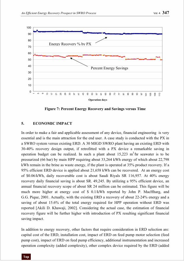
The performance of PX in terms of energy requirement for unit production of water (kWh/m3) and efficiency of energy recoveries by PX are calculated both in actual and theoretical methods. Figure 5 shows the actual and calculated energy consumption in kWh/m3 versus operation time in days, while in Figure 6 applied feed pressure and water production recoveries are plotted against operation days. Figure 7 is the plot of percent energy recovery and energy saving by PX versus time. Power model from ERI, the manufacturer of PX, is applied to verify the result. Table 1 shows the results utilizing the power model.
Three sets of calculated energy graphs are shown in Figure 5 (i) actual, (ii) calculated with actual efficiencies of pumps and (iii) calculated with optimum theoretical efficiencies (0.85 for centrifugal and 0.9 for positive displacement) of pumps. In optimum efficiency calculation
An Efficient Energy Recovery Prospect in SWRO Process Vol. 4. 345
two options are taken (1) calculating for two boosters (as the system is) and (2) considering optimum design of the system with only one booster. The calculated average energy consumption of 2.4 kWh/m3 at a product recovery of 30-32% and feed pressure of 58-59.5 kg/cm2 was achieved, Figure 5 & 6. However, when single feed booster is considered this value is further reduced to 2.2 kWh/m3 or less, Figure 5. Similar values are also obtained when manufacturer’s power model is utilized in Table 1. Due to remarkable power loss in the old HPP, the main consumer of energy, and moreover operation of the HPP at lowest possible capacity, the real observed efficiency of HPP, about 0.3, is very low as compared to actual design efficiency 0.9 [Capital Co., 1984]. For this reason the actual energy usage is higher. After about 70 days of continuous operation, a trial was made to reduce volumetric leakage through safety valve of the HPP resulted in a remarkable reduction of energy consumption. Also observed that HPP operation at its lowest capacity consumes excessive energy for unit production of water as also shown at the end of actual energy graph in Figure 5, which is true for all pumps. The maximum observed efficiency of waste energy recovery by PX is above 93%. The energy saving of about 56-58% of the total energy required to run the unit without PX addition is achieved, Figure 7. After about three months operation under initial conditions, the unit was tried to operate at different conditions with an intention to get high recovery. Due to unavailability of VFD as well as low sensitivity of V1 to control discharge pressure, the unit could not be operated at a pressure higher then 60 bar with positive results. However, the results obtained so far at feed pressure of 57-59.5 kg/cm2 were very informative and encouraging. It is very important to note that the PX and associated booster pump are handling nearly 100% of the reject flow (i.e., about 2/3 of feed flow). The main HPP handles only about 1/3 of the total feed to membrane, approximately equal to the product flow. A remarkable reduction, about 2/3, of original HPP size and consequently HPP capital cost is obvious. During about 3000 hours of operation, the HP booster with special pump construction, bearings and shaft seals did not require any maintenance. It is found that if flows are well balanced during flow adjustment, the concentrate leaks through bearing clearance into the feed stream and mixing with the feed at the feed/concentrate interface in the rotor channels remained minimum and did not affect the feed and permeate TDS remarkably. It is also noticed that slightly excess flow of LP feed to PX assists in low mixing of concentrate to feed. In some instances LP feed to PX and HP feed from PX conductivity remained almost similar. Some author [Eli Oklejas, 2002] mentioned the specially designed HP booster and feed/brine interfacial mixing as main drawbacks in PX system. During the evaluation such serious difficulties have not yet been observed.
Vol. 4. 346 A.T.M. Jamaluddin, Ata M. Hassan, Ali R. Al-Reweli, Abdullah Al-Rubaian, and Leif J Hauge
0
2
4
6
8
10
121 6
11
16
21
26
31
36
41
46
51
56
61
66
71
76
81
86
91
96
101
106
111
Operation time in days
0
10
20
30
40
50
60
70
1 6
11
16
21
26
31
36
41
46
51
56
61
66
71
76
81
86
91
96
101
106
111
116
Operation time in Days
En
erg
yk
Wh
/m3
Pre
ssu
re
kg
/cm
2a
nd
%R
eco
ver
ies
Figure 5: Actual and Calculated Energy (kWh/m3) versus Operation Time (days), PX-SWRO
Operation
Actual Energy
Energy at actual efficiencies of Pumps
Energy at Theoretical Efficiency of Pumps One Booster
Two Boosters
% Recovery
Pressure kg/cm2
Figure 6: Feed Pressure (kg/cm2), Product Recovery versus Operation Time (days), PX - SWRO
Operation.
An Efficient Energy Recovery Prospect in SWRO Process Vol. 4. 347
Figure 7: Percent Energy Recovery and Savings versus Time
5. ECONOMIC IMPACT
In order to make a fair and applicable assessment of any device, financial engineering is very essential and is the main attraction for the end user. A case study is conducted with the PX in a SWRO system versus existing ERD. A 30 MIGD SWRO plant having an existing ERD with 30-40% recovery design output, if retrofitted with a PX device a remarkable saving in operation budget can be realized. In such a plant about 15,223 m3/hr seawater is to be pressurized (66 bar) by main HPP requiring about 33,264 kWh energy of which about 22,798 kWh remain in the brine as waste energy, if the plant is operated at 35% product recovery. If a 95% efficient ERD device is applied about 21,658 kWh can be recovered. At an energy cost of $0.06/kWh, daily recoverable cost is about Saudi Riyals SR 116,957. At 40% energy recovery daily financial saving is about SR. 49,245. By utilizing a 95% efficient device, an annual financial recovery scope of about SR 24 million can be estimated. This figure will be much more higher at energy cost of $ 0.1/kWh reported by John P. MacHharg, and G.G. Pique, 2001. Actually, with the existing ERD a recovery of about 22-24% energy and a saving of about 15.6% of the total energy required for HPP operation without ERD was reported [Akili D. Khawaji, 2002]. Considering the actual case, the estimation of financial recovery figure will be further higher with introduction of PX resulting significant financial saving impact. In addition to energy recovery, other factors that require consideration in ERD selection are: capital cost of the ERD, installation cost, impact of ERD on feed pump motor selection (feed pump cost), impact of ERD on feed pump efficiency, additional instrumentation and increased operation complexity (added complexity), other complex device required by the ERD (added
Percent Energy Savings
Energy Recovery % by PX
Vol. 4. 348 A.T.M. Jamaluddin, Ata M. Hassan, Ali R. Al-Reweli, Abdullah Al-Rubaian, and Leif J Hauge
equipment), Ease of ERD repair, affect of ERD failure on other equipment, impact on membrane performance, length of down time, maintenance cost and operation simplicity. Most of these questions can be answered after completion of this research study.
6. CONCLUSIONS
1. Having the benefit of practical experience, PX can be retrofitted in old SWRO plants with remarkable financial benefit.
2. By introducing PX, a 56-58% power saving and about 68-70% size reduction of HPP is possible at 30% product recovery in SWRO plant.
3. PX has a single moving ceramic rotor part, durable, non-corrosive, with no wear under normal running conditions and required no maintenance during 3000 hours operation.
4. In SWRO plant expansion, if PX is introduced, about 2-3 time expansion of existing capacity is possible without changing the existing HPP. So it is feasible and practical to utilize PX in plant expansions.
7. REFERENCES
1. Akili D. Khawaji, Jong-Mihn Wie and Ahmed A. Al-Mutairi, 2002,“Technical and Economic Evaluation of Seawater MSF and RO Desalination Process for Madinat Yanbu Al-Sinaiyah”, Proceeding, IDA world Congress on Desalination and Water Reuse, Manama, Bahrain .
2. Antoine Riolo, 2001, Energy savings in seawater desalination in Malta, EDS Newsletter Issue 12, May
3. Capital Industries Co. Ltd., Japan, October 5, 1985, Plunger pump data sheet, Enclosed in Japan International Cooperation Agency – JICA/SWCC SWRO Operation and Maintenance Manual, March 1.
4. Eli Oklejas, 2002, “Energy Efficiency Consideration for RO Plants: A Method for Evaluation”, Desalination & Water Reuse Quarterly, Vol. 11/4.
5. Energy Recovery Inc (ERI), 2000-2001, Client List ., 1908 Doolittle drivem San Leandro, CA.
6. Energy Recovery Inc., 1908 Doolittle drivem San Leandro, CA, Technical and Application Manual, 2001.
7. G.G. Pique, 2000, “New Device Shatters seawater conversion conceptual Barriers”, Water Conditioning & Purification, July 2000.
8. John P. MacHharg, and GG Pique, 2001, “How to Design and Operate SWRO Systems Built Around a New Pressure Exchanger Device”, Proceeding, IDA world Congress on Desalination and Water Reuse, Manama, Bahrain 2002. (also John P. MacHarg, “Exchanger Tests Verify 2.0 kWh/m3 SWRO Energy Use”, Desalination & Water reuse, Vol. 1/11, 2001)
9. P. Geisler, et. al.,1995, “Pressure Exchange System for Energy Recovery in RO Plants”, Desalination 118, 91.
10. S.A. Shumway, 1999, “The Work Exchanger for SWRO Energy Recovery”, IDA Desalination & Water Reuse Quarterly, Feb./March Issue, Vol 8/4, 27.
An Efficient Energy Recovery Prospect in SWRO Process Vol. 4. 349
PX Differential HP side PSI 15 B - Seawater to PX PX Differential LP side PSI 15 C - HP Seawater from feed pump Membrane Differential PSI 25 D - HP Seawater from PX Recovery % 0.32 E - Feed to membranes F - Permeate from membranes HIGH PRESS. PUMP G - Concentrate from membranes Feed Pump eff 0.85 H - Concentrate discharge Motor eff 0.92 PX Differential from graph Power kW 2.7 Membrane differential assumed BOOSTER PUMP Total RO Process (kW) 3.1 Boost Pump Eff 0.60 Motor Eff 0.92 kWh/m3 Permeate 2.24 Power kW 0.4 kWh/1000 gal Permeate 8.48 Seawater Feed Pump kW 0.0 Power savings/yr @ $0.10/kWh $3,825 Flow parameters and power requirements are based on assumed values. Energy losses due to piping and piping components are neglected and in practice should be minimized. Low energy requiremets will be achieved by using a variable frequency drive to control booster pump flow.


![Flow Visualization of Multiphase Flow Systems - KFUPMsadiq/proceedings/SEC2002/vol5/P661.pdf · Chemical Engineering Department, ... (For example, see [Degaleesan, 1997], [Rados,](https://static.documents.pub/doc/80x56/5b1d3c687f8b9a0b2c8be9c8/flow-visualization-of-multiphase-flow-systems-sadiqproceedingssec2002vol5p661pdf.jpg)


