1. Introduction When I go out with a portable station on 23cm I often use a 55-element Tonna antenna that has a very narrow beamwidth. I prefer to manually turn the antenna because it is quicker and easier to line up on a distant station. There are two problems with that: • It is impossible to see the antenna at night so it is difficult to see where the antenna is pointing • If it is bad weather, with rain, it is an unpleasant experience looking out to see where the antenna is pointing For a long time I wanted some form of electronic compass fixed to the antenna with a display in the shack (tent or car). With the increase in home made robots various sensors have become available at a reasonable price. This compass is based around a small unit available from robot component suppliers with two magnetic sensors at right angles and a PIC to do Andy Barter, G8ATD An Electronic Compass Fig 1: Block diagram of the electronic compass. VHF COMMUNICATIONS 3/2012 172
Transcript
1.Introduction
When I go out with a portable station on23cm I often use a 55-element Tonnaantenna that has a very narrowbeamwidth. I prefer to manually turn theantenna because it is quicker and easierto line up on a distant station. There aretwo problems with that:
• It is impossible to see the antennaat night so it is difficult to see
where the antenna is pointing
• If it is bad weather, with rain, it isan unpleasant experience lookingout to see where the antenna ispointing
For a long time I wanted some form ofelectronic compass fixed to the antennawith a display in the shack (tent or car).With the increase in home made robotsvarious sensors have become available ata reasonable price. This compass is basedaround a small unit available from robotcomponent suppliers with two magneticsensors at right angles and a PIC to do
Andy Barter, G8ATD
An Electronic Compass
Fig 1: Block diagram of the electronic compass.
VHF COMMUNICATIONS 3/2012
172
the maths to work out the direction that itis pointing.I have recently found the PICAXE mi-crocontroller family and for someone likeme who can write a simple program butis not a programmer they are ideal to turn
the output of the compass board intosomething that can display remotely inthe shack. The PICAXE is programmedin a Basic like language with some veryuseful statements that make talking toI2C buses and RS232 links very easy.The PICAXE development software that
Fig 2: The HeadUnit mounted onthe mast.
Fig 3: The DisplayUnit in the shack(tent).
VHF COMMUNICATIONS 3/2012
173
runs on a PC is free to download from[1]. Once a program is written it is easilytransferred to the PICAXE microcontrol-ler via the in circuit programming con-nection using a cable from either a serialport on your PC or using a special USBcable.
2.Description of the compass
Fig 1 shows a block diagram of thecompass. It is split into two units; theHead Unit mounted at the top of the mast(Fig 2) and the Display Unit (Fig 3) thatsits in the shack with a digital display ofthe bearing.The Head Unit contains the CMPS03compass board [2] that has several out-puts to send the direction that it ispointing to the outside world. Becausethe PICAXE has a very simple way tocommunicate with an I2C bus, I chosethat method to pick up the output. ThePICAXE microcontroller does a simplejob of taking the direction informationthat is output as 0 – 3599 and sending itdown to the shack over an RS232 link.The Display Unit contains a secondPICAXE microcontroller to receive theRS232 data sent by the Head Unit anddisplaying it on 3 large seven-segmentdisplays.I built this project to check if this typeelectronic compass would be accurateenough and useful enough to be worthdeveloping further.
3.The Head Unit
Fig 4 shows the circuit diagram of theHead Unit. It is fairly straightforwardwith a 5v regulator generating the inter-
nal 5v supplies from a 12v supply sent upthe cable from the shack. The CMPS03compass board requires a 5v supply andthe I2C bus (SDA and SCL) are con-nected to the PICAXE microcontroller,the bus connections have 4k7Ω pull upresistors.The CMPS03 board comes pre-calibratedand I have not recalibrated mine but thereis provision to calibrate it for your cho-sen location. The calibration process isdescribed in the literature on [2], itinvolves connecting the calibrate pin to0v and accurately pointing the unit at thecompass cardinal points. The circuit in-cludes header pins to connect the cali-brate pin to 0v and an LED to indicatethat the calibration process is being car-ried out.The PICAXE program (Table 1) readsthe I2C bus and picks out the bearingdata sent as 0000 to 3599. This isconverted from the two-byte word intofive ASCII characters then sent via aMAX3223 RS232 driver to the DisplayUnit. Only the most significant fourcharacters are sent because the fifth is thedecimal digit of the bearing and notthought worth displaying. The messagesent is “BRGnnnn” this enables thePICAXE microcontroller in the DisplayUnit to synchronise with the data beingsent by detecting the “BRG” in the stringsent.The PCB and component layouts areshown in Figs 5 and 6. The unit is housedin a plastic box using all nylon screws forfixings to minimise the local magneticfields (Fig 7). The box is fixed to a shortpiece of square aluminium tube that isattached to the mast with a standard mastclamp (Fig 8). The Head Unit is con-nected to the Display Unit with a 3-corecable.
VHF COMMUNICATIONS 3/2012
174
F
ig 4
: Cir
cuit
diag
ram
of t
he H
ead
Uni
t.
VHF COMMUNICATIONS 3/2012
175
Fig 8: The HeadUnit mounted onan aluminium barto attach to themast with astandard U bolt.
Fig 7: The HeadUnit mounted in itsplastic case. Allnylon screws usedto reduce the"local" magneticfield.
Fig 6: Componentlayout for the HeadUnit.
Fig 5: PCB layoutfor the Head Unit.
VHF COMMUNICATIONS 3/2012
176
F
ig 9
: Cir
cuit
diag
ram
of t
he D
ispl
ay U
nit.
VHF COMMUNICATIONS 3/2012
177
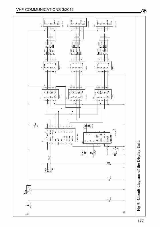
4.Display Unit
Fig 9 shows the circuit diagram of theDisplay Unit. It is fairly straightforwardwith a 5v regulator generating the inter-nal 5v supplies from a 12v supply. TheRS232 data coming from the Head Unitis fed to a MAX3223 for conversion toTTL levels and then fed to pin IN0 of thePICAXE microcontroller. The data re-quired is taken out of the data stream andfed to the lower four bits of the outputport (OUT0 – OUT3). These are con-nected to three MC14513 7-segmentlatch/display drivers, the latch inputs ofeach one is fed from a different pin onthe PICAXE output port so that thecorrect data can be stored in the latchwhen it is available. The segment outputsare connected to ULN2003 buffers tofeed the SA12-11 1.2 inch 7-segmentdisplays.The PICAXE program (Table 2) uses the“serin” statement of the PICAXE that
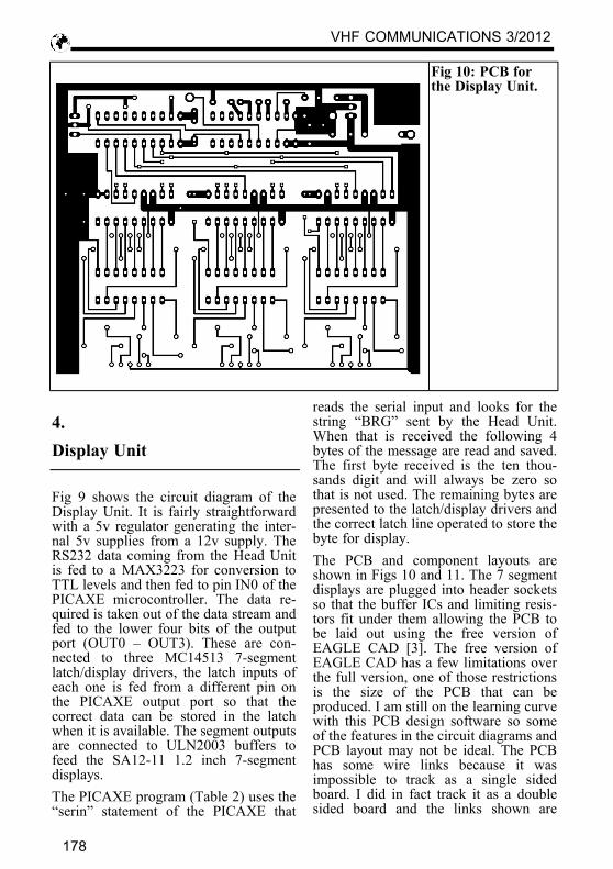
reads the serial input and looks for thestring “BRG” sent by the Head Unit.When that is received the following 4bytes of the message are read and saved.The first byte received is the ten thou-sands digit and will always be zero sothat is not used. The remaining bytes arepresented to the latch/display drivers andthe correct latch line operated to store thebyte for display.The PCB and component layouts areshown in Figs 10 and 11. The 7 segmentdisplays are plugged into header socketsso that the buffer ICs and limiting resis-tors fit under them allowing the PCB tobe laid out using the free version ofEAGLE CAD [3]. The free version ofEAGLE CAD has a few limitations overthe full version, one of those restrictionsis the size of the PCB that can beproduced. I am still on the learning curvewith this PCB design software so someof the features in the circuit diagrams andPCB layout may not be ideal. The PCBhas some wire links because it wasimpossible to track as a single sidedboard. I did in fact track it as a doublesided board and the links shown are
Fig 10: PCB forthe Display Unit.
VHF COMMUNICATIONS 3/2012
178
tracks that were placed on the upper layerwith vias where the wire links connect.The unit is housed in a plastic box withthe PCB mounted on the front panel andthe displays showing through a cutout. A3-pin din socket is used to connect thecable to the Head Unit.
5.Performance
The electronic compass was used inanger for the first time for the RSGBVHF NFD at the beginning of July. Itwas found to be accurate to within ±3degrees when peaking up on a weaksignal and comparing the displayed head-ing with that calculated using the QRAlocator of the distant station. There wasan unexpected benefit that meant that anyweak stations heard but not worked couldbe found again accurately by notingdown the heading displayed and thefrequency. Stations tend to stay on thesame calling frequency during a contestso this technique worked well especially
since conditions were pretty poor. Theother benefit was that only my lower armgot wet in the atrocious weather.
6.Conclusion
The project was fairly easy and the endresults were better that expected. It isperfectly useable in its present state andis certainly worth developing further. Theonly problem discovered was that the1.2-inch LEDs were not bright enoughfor strong daylight conditions. Perhapsincreasing the display current will over-come that shortcoming. I am now plan-ning to write a Windows program todisplay the bearing and a compasspointer in a window on the loggingcomputer. My Windows programmingskills are less than my PICAXE skills sothat project may take some time. Whilstsearching for the right programming toolto do the job I came across a commercialunit that does the same job [4]. If youcan’t wait for the Windows program, it
Fig 11: Componentlayout for theDisplay Unit. The1.2 inch LEDdisplays aremounted on headersockets so that theysit above the bufferICs and limitingresistors.
VHF COMMUNICATIONS 3/2012
179
will not be a good as the Sierra Radioversion, then there is a ready madeoffering available.
7.References
[1] PICAXE - http://www.picaxe.com/
[2] CMPS03 -http://www.robot-electronics.co.uk/htm/cmps3tech.htm[3] Eagle CAD -http://www.cadsoftusa.com/[4] Sierra Radio compass -http://www.hamstack.com/ss_compass.html
; PICAXE electronic compass 20/5/2012 ; Reads the I2C output from a CMPS03 compass module ; The output is a single byte showing the revision level - not used ; A single byte with the direction as 0 - 255 - not used ; A word (two bytes) with the direction as 0 - 3599 ; The direction word is converted to an ASCII string and transmitted at 600 baud ; over a serial link with a header of "BRG"
symbol BEARING_1 = b7 ; CMPS03 Bearing word high byte symbol BEARING_2 = b6 ; CMPS03 Bearing word low byte
; b6 and b7 are referred to as w3 - word 3 symbol BEARING = b27 ; CMPS03 Bearing byte 0 - 255 - not used symbol RE = b26 ; CMPS03 revision byte - not used symbol BTTH = b14 ; Bearing ten thousands symbol BTH = b13 ; Bearing thousands symbol BHND = b12 ; Bearing hundreds symbol BTEN = b11 ; Bearing tens symbol BUNIT = b10 ; Bearing units
main: ; main program loop gosub rdcompass ; read the compass and output serial data pause 1000 ; wait a while goto main ; go round again
rdcompass: ; read compass hi2csetup i2cmaster,$C0, i2cslow, i2cbyte ; initialise compass on I2C bus hi2cin 0,(RE, BEARING, BEARING_1, BEARING_2) ; read compass via I2C bus bintoascii w3,BTTH,BTH,BHND,BTEN,BUNIT ; convert bearing word - word 3 - to ASCII serout C.7, T600_4, ("BRG",BTTH, BTH, BHND, BTEN) ; send data at 600 baud to pin C.7
return
Table 1: Head Unit PICAXE program.
VHF COMMUNICATIONS 3/2012
180
Table 2: Display Unit PICAXE program.
; PICAXE electronic compass display 26/5/2012 ; Receives bearing data string from Head Unit and displays on 7 segment LEDs; Bearing data in string is: Ten Thousands digit - not requires ; Thousands digit - MSD of display ; Hundreds digit - middle digit of display ; Tens digit - LSD of display
symbol BEARING_1 = b9 ; Bearing hundreds symbol BEARING_2 = b7 ; Bearing tens symbol BEARING = b5 ; Bearing thousands;
start: let dirsB = 255 ; Set pins on port B to outputs let BEARING = 0 ; initialise bearing high b.4 ; Set thousands display digit latch line high high b.5 ; Set tens display digit latch line high high b.6 ; Set units display digit latch line high
main: ; main program loop serin C.0, T600_4, ("BRG"),b2, BEARING, BEARING_1, BEARING_2 ; read the serial port ; b2 holds ten thousands digit - not required ; BEARING holds thousands digit - MSD of display ; BEARING_1 holds hundreds digit ; BEARING-2 holds tens digit - LSD of display ; Display shows 0 - 359 from 0 - 3599 let b1 = BEARING ; Set b1 = thousands digit let b1 = b1 & 15 ; Mask off top 4 bits let b1 = b1 + 240 ; Make top 4 bits high - they are used for display latch let pinsB = b1 ; Write b1 to the B port - sends digit to display low b.4 ; Set thousands digit latch low to store data in display driver pause 10 ; Wait a while high b.4 ; Set latch high let b2 = BEARING_1 ; Set b2 = hundreds digit let b2 = b2 & 15 ; Mask off top 4 bits let b2 = b2 + 240 ; Make top 4 bits high - they are used for display latches let pinsB = b2 ; Write b2 to the B port - sends digit to display low b.5 ; Set hundreds digit latch low to store data in display driver pause 10 ; Wait a while high b.5 ; Set latch high let b3 = BEARING_2 ; Set b3 = tens digit let b3 = b3 & 15 ; Mask off top 4 bits let b3 = b3 + 240 ; Make top 4 bits high - they are used for display latches let pinsB = b3 ; Write b3 to the B port - sends digit to display low b.6 ; Set tens digit latch low to store data in display driver pause 10 ; Wait a while high b.6 ; Set latch high goto main ; Go round again