An Electronic Quadrature Technique for Laser Interferometry J. W. Campbell and Virgil Erbert Sandia Laboratory, Albuquerque, New Mexico. Received 30 January 1967. This work was supported by the U.S. Atomic Energy Com- mission. The (LFI) Laser Feedback Interferometer 1 consists of a cw laser and an external retroreflector (Fig. 1). This interferometer has the advantage of requiring no tedious alignment other than that of positioning the retroreflector so that the returned laser beam is approximately centered. The distance between the retro- reflector and the output mirror of the laser is the parameter of in- terest in metrological applications. A uniform translation of the retroreflector along the laser beam will produce a sinusoidal in- tensity variation in the laser output when the amount of optical 1128 APPLIED OPTICS / Vol. 6, No. 6 / June 1967
Transcript
An Electronic Quadrature Technique for Laser Interferometry J. W. Campbell and Virgil Erbert
Sandia Laboratory, Albuquerque, New Mexico. Received 30 January 1967. This work was supported by the U.S. Atomic Energy Commission.
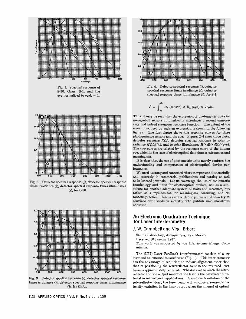
The (LFI) Laser Feedback Interferometer1 consists of a cw laser and an external retroreflector (Fig. 1). This interferometer has the advantage of requiring no tedious alignment other than that of positioning the retroreflector so that the returned laser beam is approximately centered. The distance between the retroreflector and the output mirror of the laser is the parameter of interest in metrological applications. A uniform translation of the retroreflector along the laser beam will produce a sinusoidal intensity variation in the laser output when the amount of optical
1128 APPLIED OPTICS / Vol. 6, No. 6 / June 1967
Fig. 1. Schematic illustration of laser feedback interferometer.
Fig. 2. Block diagram for obtaining quadrature signals with model 119.
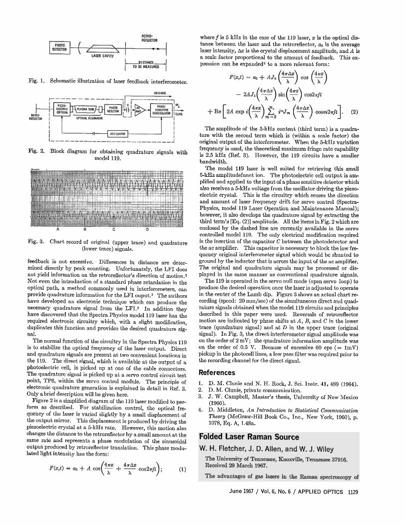
Fig. 3. Chart record of original (upper trace) and quadrature (lower trace) signals.
feedback is not excessive. Differences in distance are determined directly by peak counting. Unfortunately, the LFI does not yield information on the retroreflector's direction of motion.2
Not even the introduction of a standard phase retardation in the optical path, a method commonly used in interferometers, can provide quadrature information for the LFI ouput.3 The authors have developed an electronic technique which can produce the necessary quadrature signal from the LFI . 3 In addition they have discovered that the Spectra Physics model 119 laser has the required electronic circuitry which, with a slight modification, duplicates this function and provides the desired quadrature signal.
The normal function of the circuitry in the Spectra Physics 119 is to stabilize the optical frequency of the laser output. Direct and quadrature signals are present a t two convenient locations in the 119. The direct signal, which is available at the output of a photoelectric cell, is picked up at one of the cable connectors. The quadrature signal is picked up at a servo control circuit test point, TP6, within the servo control module. The principle of electronic quadrature generation is explained in detail in Ref. 3. Only a brief description will be given here.
Figure 2 is a simplified diagram of the 119 laser modified to perform as described. For stabilization control, the optical frequency of the laser is varied slightly by a small displacement of the output mirror. This displacement is produced by driving the piezoelectric crystal a t a 5-kHz rate. However, this motion also changes the distance to the retroreflector by a small amount a t the same rate and represents a phase modulation of the sinusoidal output produced by retroreflector translation. This phase modulated light intensity has the form:
where ƒ is 5 kHz in the case of the 119 laser, x is the optical distance between the laser and the retroreflector, a0 is the average laser intensity, Δx is the crystal displacement amplitude, and A is a scale factor proportional to the amount of feedback. This expression can be expanded4 to a more relevant form:
The amplitude of the 5-kHz content (third term) is a quadrature with the second term which is (within a scale factor) the original output of the interferometer. When the 5-kHz variation frequency is used, the theoretical maximum fringe rate capability is 2.5 kHz (Ref. 3). However, the 119 circuits have a smaller bandwidth.
The model 119 laser is well suited for retrieving this small 5-kHz amplitudefunct ion. The photoelectric cell output is amplified and applied to the input of a phase sensitive detector which also receives a 5-kHz voltage from the oscillator driving the piezoelectric crystal. This is the circuitry which senses the direction and amount of laser frequency drift for servo control (Spectra-Physics, model 119 Laser Operation and Maintenance Manual) ; however, it also develops the quadrature signal by extracting the third term's [Eq. (2)] amplitude. All the items in Fig. 2 which are enclosed by the dashed line are currently available in the servo controlled model 119. The only electrical modification required is the insertion of the capacitor C between the photodetector and the ac amplifier. This capacitor is necessary to block the low frequency original interferometer signal which would be shunted to ground by the inductor that is across the input of the ac amplifier. The original and quadrature signals may be processed or displayed in the same manner as conventional quadrature signals.
The 119 is operated in the servo null mode (open servo loop) to produce the desired operation once the laser is adjusted to operate in the center of the Lamb dip. Figure 3 shows an actual chart recording (speed: 20 mm/sec) of the simultaneous direct and quadrature signals obtained when the model 119 circuits and principles described in this paper were used. Reversals of retroreflector motion are indicated by phase shifts a t A, B, and C in the lower trace (quadrature signal) and at D in the upper trace (original signal). In Fig. 3, the direct interferometer signal amplitude was on the order of 2 mV; the quadrature information amplitude was on the order of 0.5 V. Because of excessive 60 cps (≈ ImV) pickup in the photocell lines, a low pass filter was required prior to the recording channel for the direct signal.
References 1. D . M. Clunie and N. H. Rock, J. Sci. Instr. 41 , 489 (1964). 2. D . M. Clunie, private communication. 3. J . W. Campbell, Master 's thesis, University of New Mexico
(1966). 4. D . Middleton, An Introduction to Statistical Communication
Theory (McGraw-Hill Book Co., Inc., New York, 1960), p . 1078, Eq . A, 1.48a.