AN EVALUATION OF MARINE PROPULSION-.. am ENGINES FOR SEVERAL NAVY SHIPS D T IC &ý- by LEcTE Mark Thomas Stanko SEP 0 1992n B.S.M.E., University of Utah A < -•--1983 SUBMIlTED TO THE DEPARTMENT OF OCEAN ENGINEERING AND MECHANICAL ENGINEERING IN PARTIAL FULFILLMENT OF THE REQUIREMENTS FOR THE DEGREES OF NAVAL ENGINEER and MASTER OF SCIENCE IN MECHANICAL ENGINEERING at the MASSACHUSETTS INSTITUTE OF TECHNOLOGY May 1992 C)Massachusetts Institute of Technology, 1992. All rights reserved. Signature of Author & • ILM18- Department of Ocean Engineering and Mechanical Engineering 1992 Certified by C). C. •g -. D. G. Wilson Thesis Reader Accepted by vq . Kj o /010 "Douglas Carmichael Thesis Supervisor and Chairman, Departmental Graduate Committee Department of Ocean Engineering This document has boen appoved fot public release and sale; its distribution is unlimited. I 92-24092 92 8 31 009 N
Transcript
AN EVALUATION OF MARINE PROPULSION-..
am ENGINES FOR SEVERAL NAVY SHIPS D T IC&ý- by LEcTEMark Thomas Stanko SEP 0 1992n
B.S.M.E., University of Utah A< -•--1983
SUBMIlTED TO THE DEPARTMENT OF OCEAN ENGINEERING AND MECHANICAL
ENGINEERING IN PARTIAL FULFILLMENT OF
THE REQUIREMENTS FOR THE DEGREES OF
NAVAL ENGINEER
and
MASTER OF SCIENCE IN MECHANICAL ENGINEERING
at the
MASSACHUSETTS INSTITUTE OF TECHNOLOGY
May 1992
C)Massachusetts Institute of Technology, 1992. All rights reserved.
Signature of Author & • ILM18-Department of Ocean Engineering and
This document has boen appovedfot public release and sale; itsdistribution is unlimited.
I 92-24092
92 8 31 009 N
AN EVALUATION OF MARINE PROPULSION
ENGINES FOR SEVERAL NAVY SHIPS
by
Mark Thomas StankoSubmitted to the Departments of Ocean Engineering and Mechanical Engineering
on May 1, 1992 in partial fulfillment of the requirements for the Degrees of NavalEngineer and Master of Science in Mechanical Engineering
ABSTRACT
The design of naval ships is a complex and iterative process. The propulsion system isselected early in the design cycle and it has significant impact on the ship design. Acomplete understanding of the marine propulsion engine alternatives is necessary tofacilitate the design.
Five types of marine propulsion engines have been examined and compared. Theyinclude an LM-2500 marine gas turbine, an Intercooled Recuperative (ICR) marine gasturbine, a series of Colt-Pielstick PC4.2V medium speed diesels, a series of Colt-PielstickPC2.6V medium speed diesels, and an Allison 571-KF marine gas turbine module powerpak.
To facilitate an integrated propulsion systems study, an engine's computer model hasbeen written that calculates the engine weight, volume, fuel consumption, and acquisitioncost. Given user input for propulsor and transmission performance, the engine code willalso calculate the required endurance fuel load in accordance with Navy standards.The Engine's computer code allows the user to employ different engine types for cruiseand boost operating regimes. The model ensures that the engines are operated withintheir horsepower and RPM ratings and splits the propulsion load evenly when multipleengines are in use.
The engine's computer code will be integrated into a complete propulsion systemscomputer code. This will facilitate the analysis of various propulsion alternatives forNavy ships.
This thesis is one part of the three-part propulsion system study. The other two parts arethe evaluation of transmissions for a ship's propulsion system, and the evaluation ofpropulsors for a ship's propulsion system.
Thesis Supervisor: A. Douglas Carmichael, Professor of Ocean EngineeringThesis Reader. David Gordon Wilson, Professor of Mechanical Engineering
2
ACKNOWLEDGEMENTSI
I wish to thank my advisor, Professor A. D. Carmichael. His support and guidance
thfoughout this project have been both very helpful and illuminating.
CHAPTER 4 THE ELECTRIC PLANT GENERATOR SETCONSIDERATIONS ............................................................... 38
4.0 O verview ................................................................................................ 38
4.1 The DDG Electric Plant Options ............................................................ 38
4.2 The LX Electric Plant Options ................................ 41
4
CHAPTER 5 OVERVIEW OF THE INTEGRATED PROPULSIONSYSTEM COMPUTER CODE STRUCTURE ............. 43
5.0 O verview ................................................................................................ 43
5.1 The Integrated Codes Basic Structure ..................................................... 43
CHAPTER 6 DEVELOPMENT OF THE ENGINE FUNCTIONSFOR THE INTEGRATED PROPULSION SYSTEMSCOM PUTER CODE ................................................................ 46
6.0 O verview ................................................................................................ 46
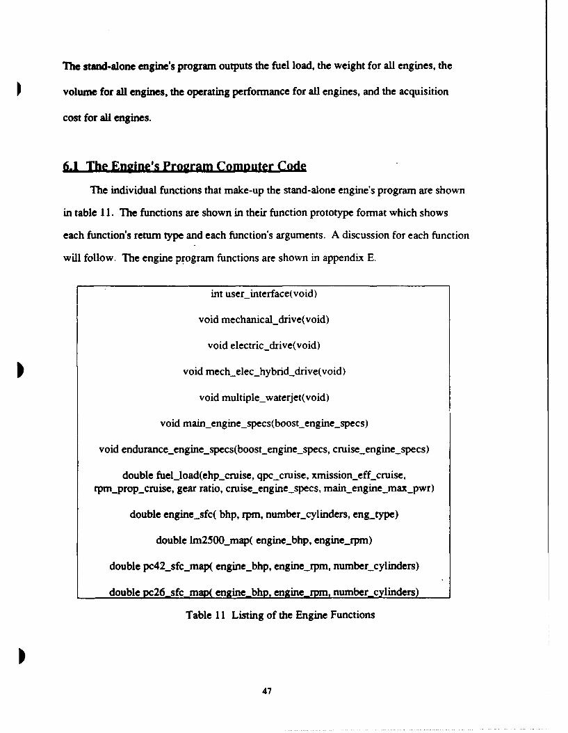
6.1 The Engine's Program Computer Code ................................................... 47
CHAPTER 7 SUM M ARY ............................................................................. 56
R E FE R E N C E S ................................................................................................ 57
APPENDIX A SPECIFIC FUEL CONSUMPTION MODELLING ............... 59
APPENDIX B INTAKE AND UPTAKE WEIGHT CALCULATIONS ...... 73
APPENDIX C INTAKE AND UPTAKE VOLUME CALCULATIONS ..... 75
APPENDIX D FUEL WEIGHT CALCULATIONS ..................................... 79
APPENDIX E DETAILED LISTING OF COMPUTER CODE .................... 83
APPENDIX F SAMPLE OF OUTPUT ............................................................ 133
I
LIST OF FIGURES
Figure 1 The LM-2500 Marine Gas Turbine ................................................. 15
Figure 2 The Simple Cycle Gas Turbine ....................................................... 15
Figure 3 LM-2500 with assumed Cubic Loading ...................... 16
Figure 4 LM-2500 Bleed Air Discharge Pressure versus Engine BHP ....... 17
Figure 5 LM-2500 Engine SFC for Cubic Loading ......................... 19
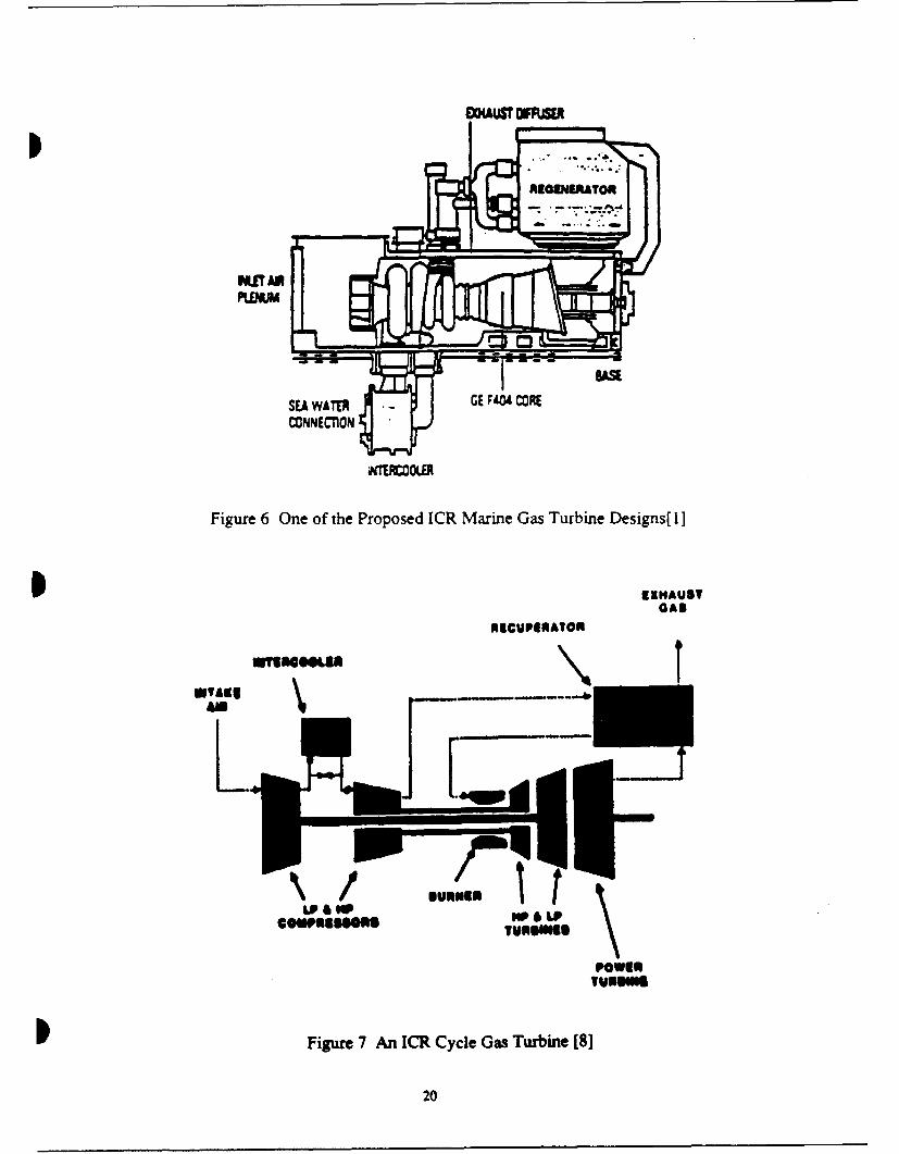
Figure 6 One of the Proposed ICR Marine Gas Turbine Designs .................. 20
Figure 7 An ICR Cycle Gas Turbine ............................................................. 20
Figure 8 ICR Gas Turbine SFC for Cubic Loading ....................................... 22
Figure 9 The Allison 571-KF Marine Gas Turbine ....................................... 23
Figure 10 The 571-KF Marine Gas Turbine Power Pak Module .................... 23
Figure 11 571-KF Engine SFC for Cubic Loading ........................................ 25
Figure 13 Available Colt-Pielstick Medium Speed Diesel Engine Options [11I]0
27
]Figure 14 provides a description for the four stroke Colt-Pielstick diesel engine's
principle of operation. The PC4.2V and PC2.6V are very similar in design and
construction. The primary difference is in the power rating and thus size of the
components. Both engines incorporate the vee cylinder arrangement. Direct reversing
engines are available, but were not considered for this project. As a result either a
reversing gear or a CRP propeller will have to be used for reversing. It is assumed that
the diesels will be ran on DFM fuel at the conditions prescribed in table 3. The engines
can be configured to run on various grades of heavy fuel. However, this requires
upgrading the exhaust valves and engine fuel systems to run on the harsher fuel. The
engines incorporate turbocharging with each bank of cylinders in the vee configuration
served by its own turbocharger.
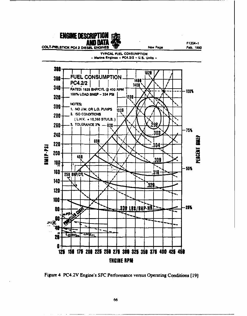
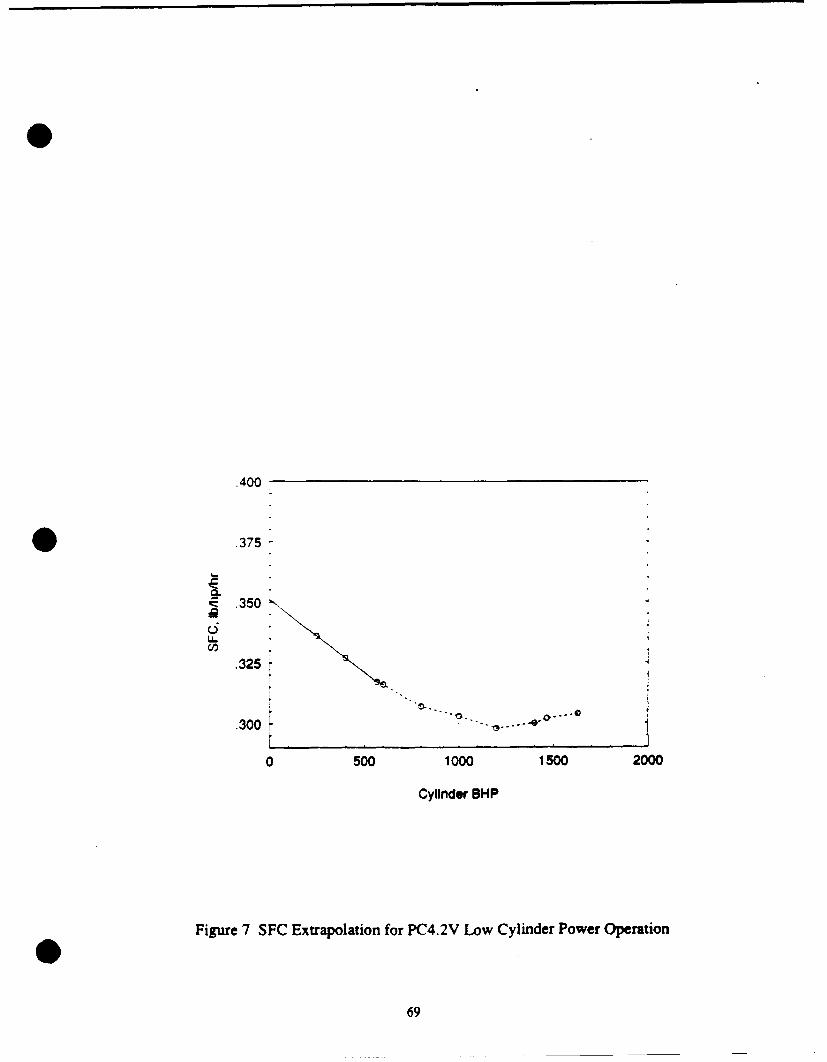
The PC4.2V diesel engine is rated at 1629 BHP per cylinder. The engine operates
between 125 and 400 RPM. The SFC for the engine, assuming cubic engine loading, is
shown in figure 15. An engine model was developed that maps the engine SFC as a
function of BHP and RPM. The details for the development of the diesel SFC model can
be found in appendix A.
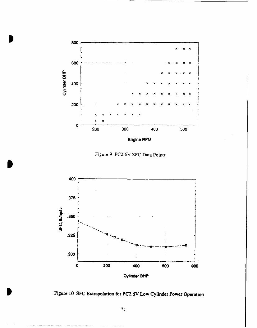
The PC2.6V diesel engine is rated at 737 BHP per cylinder. The engine operates
between 200 and 520 RPM. The SFC for the engine, assuming cubic engine loading, is
shown in figure 16.
28
AMI go SuDWeadas F1232-3COT4 TC 11142CSEEL INGINIE Ft232-S Jan. 19gP iue 1990
PRiN4OFL OF OPERATION01*0.1 (OlgIlilato at Heavy Fuels) Engines
These engines aS ogorate On the *fOulr Stroke " tinan comimences. D.ie to tiehee MAIOf COi1111tton.cycle, thale Is. AM events - & intake. comore-sem . the gaemsuepa". resultn in an almiioal vistantane.1itW bidnfkS5I. cornlbi~e. expanuion. eithausk. cue increase in a~b~ oresvire. This forces tfeanW scavenging, occur "ii four strokes@ of the piston down an the poww stroke (3).piston or two revokiltlons of the cranksh~aft (7201). Just before, 60C. thes exhaust Valves open andSee Fig. I. remain open throughout the exhaust Stroke (4) And
Starting at 0* TOC w"ti the sir intake valves al- ito the intake Strokce before ciosin. The air intakeready open, the piston moves down and MI, .5 adimit- valves open during thle Oxhust stroke AMi both Ais!0d to the cylinder (1). Shortly after 8OC. the at and exhlaust raVIPQesar Ope aSftiutsrlosty forritake valve$ close, the CYki~dr iS therefore Samated about 94" at rotat~io. This ovartap, allows *icomingand compression takes place on the Upward Stroke Air to purga the cykindw Of aO exhauSt gas and $ISO(2). 'A* host of the Sir finaresa due to compro9. aids in cooling the piston crown. upper cylinda andSion and fuel is injected shortly before TOC. rhofel edisxhust VAN"e.is mmediate" ignited by th hot &lW, Anid Con%"-.
AI INTAKE VALVE NOTE: Timing ~hown mrnoinall design. individualapplocations may require modification Each
INJECTOR Situation rsquireS avaluatiol by FairbanksECHAUST VALVE 'erie Engineering.
0 *00
urn UNCIM amW"e
MOU . i at M O - Pr - UU
Fiur 14 CotPeskDee nieP inilofOeaos12
COP IVMA TO I OSNO E= MTLGIL m mro- .me l29
.35 90 degrees F ambient
85 degrees F intercool9r H20 Inletno engine, driven jacket water or*
•, Qlube all pumps
.33 "
.31 ""
.290 1000 1500
Cylinder BHP
Figure 15 PC4.2V Diesel Engine SFC for Cubic Loading
S.36
7
90 degrees F ambient85 degrees F intercooler H20 inletno engine driven jacket water or
.34 lube oil pumps
U.3Wci .
.32
.300 200 400 600 800
Cylinder BHP
Figure 16 PC2.6V Diesel Engine SFC for Cubic Loading
330
ComDarison of The Marine Propulsion EngineA
3.0 Overvie
Determining the impact of a propulsion system on a ship requires that the analysis
consider the synergistic integration of all the propulsion components. However, a
comparison of the individual technologies within a component group can help to identify
the specific individual promising technologies. With this motivation, the selected
propulsion engines are compared.
3.1 Boost Engine Options
As described in chapter 2, the designated boost engines were selected to meet the
projected power requirements for minimum sustained speed. Depending on the specific
selection for the propulsion plant components, the engines may also be used for cruise
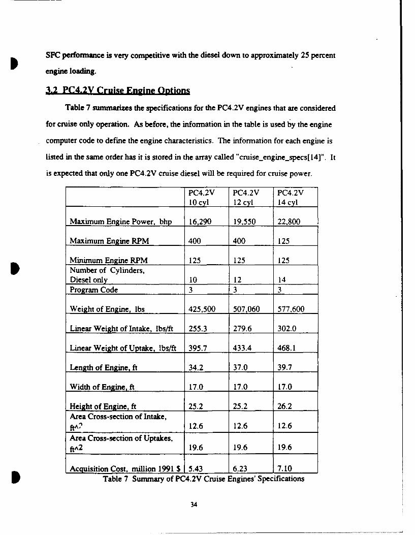
operation. Table 4 provides a summary of the specifications for the boost engines.
The information in the table is used by the engine computer code to define the
engine characteristics. The information for each engine is listed in the same order has it
is stored in the array called "boostengine.specs[ 14]". The program code is a value used
by the computer code to identify the engine type and control branching logic.
Since the locations of the engines in the ship may vary depending on the propulsion
system and the specific arrangement requirements, the intake and uptake ducting weight
and volume will vary. Therefore the average weight per linear foot and the average cross
sectional area per linear foot of ducting were calculated as detailed in appendix B and
appendix C, respectively. Once the engine is placed and the length of ducting is known,
the total weight and volume for the engine ducting can be calculated by multiplying by
the known duct length.
331
LM-2500 ICR PC4.2 Allison16 cyl 571-KF
Power Pak
Maximum Engine Power, 26,250 26,400 26,060 6000bhp
Maximum Engine RPM 3600 3600 400 1800
Minimum Engine RPM 1200 1200 125 900Number of Cylinders,Diesel's only 16Program Code 1 2 3 5
Weight of Engine, lbs 59,000 120.000 639,340 15,000
Linear Weight of Intake, lbs/ft 493.2 494.5 322.9 364.5
Linear Weight of Uptake, lbs/ft 799.0 801.1 500.5 590.5
SLength of Engine, ft 26.5 26.5 42.7 15.8
Width of Engine, ft 8.7 8.7 17.0 5.7
Height of Engine, ft 10.4 22.2 26.2 7.7Area Cross-section of Intake,fi^2 119.7 119.7 12.6 37.3
Area Cross-section of Uptakes,ftA2 162.5 162.5 19.6 82.3
Acquisition Cost, million 1991 $ 4.5 6.5 7.8 3.5
Table 4 Summary of Boost Engines' Specifications
The acquisition cost for the Allison 571 -KF Power Pak was quoted by the
manufacturer [13] and includes all of the module components but does not include the
cost for spare parts. The other engines' cost were reported from NAVSEA [14]. All gas
turbine costs figures include the acquisition items shown in table 5. All diesel costs
figures include the acquisition items shown in table 6.
double pc26_ sfc map( engine_bhp, enginerpm, number cylinders)
Table 11 Listing of the Engine Functions
47
The first five functions shown in table 11 perform the input operation. They
I provide an interactive user interface that guides the user through the selection of the
individual components for the propulsion system. The user selected choices are stored in
a 7 by 2 two dimensional array called planLmap which is shown in table 12. Each cell
of the array contains information about the propulsion system. The individual cells,
shown in table 12, display all the possible values for a given selection. However in some
cases, depending on the selected drive system, not all of the possible values will
available. The functions incorporate bounds checking to ensure that the user only inputs
one of the accepted values. The plant-map array is declared has a global array so that
any function can access the plant-map array to obtain information about the proposed
propulsion system.
The userinterface function initiates the input process. However, the logic required
to step through the entire input process depends on the type of drive system. Therefore
the userinterface function calls one of the next four functions to complete the input
process. At the end of the selection process, the userinterface function provides a
summary of the selections and offers the choices of running the program. re-selecting the
propulsion system, or quitting the program.
If the propulsion system is mechanical drive, the mechanicaldrive function steps
through the input process. The function's logic allows for two or three propulsion shafts.
If three propulsion shafts are selected, the cross-connect gear option is not allowed. The
user selects either the LM-2500, the ICR, or the 16 cylinder PC4.2V as the boost engine.
If the LM-2500 is selected, then the user is given the opportunity to select a different
type of engine for cruise. The cruise engine options are the ICR, the 10 cylinder
PC4.2V, or the 10 cylinder PC2.6V. The fuelload function, called later in the program,
will check the power ratings on the cruise diesels and if necessary, it will automatically
increase the number of cylinders to meet the endurance power requirement. The user
D then selects the number of cruise engines and the number of boost engines that will be
48
PLAINTrMUAP IF1 PLANT •N-r I XII
CRUMECONDrIloN BOOST oONITflON
NUMBER OP PROPUL.SORS USED POR NUMBER OP PtOPULSOSS USED POF
CatUSL BOO6ST,
I . ONE 2-TWO
ROW10| 2- TwO 3- THIREE
4-TMU 4R- POUR
__6-aX $. .MORT
PRGPULSOR DESIGNATION CODE HYBID DRIVE XMIUION TYpu
1-F?? 0- NONE•
2-CRP 1 -EELEC1TRICTO MECH
3 - CONTRA-ROTATING
ROW1] 4.PRESWIRL S'tATOR
S - DUCTIED PF?
6 -DUCTED CRP
7 .DUCTED CONTRA
I - DUCTED PRESWTRL
9 - WATERJET
TRANSMISSION DESIGNATION CODE. TRANSMISSION TYPE CODE:
I - MECHANICAL DRIVE 0 - NONE
ROW12] 2 - ELECTRIC DRIVE I - EPICYCLUC
3 - HYBRID 2 - LTDR
4- MULTIPLE WATERJET 3 - LTDR -AEVERSING
4- LTDR W/CROSSCONNECT
CRUISE ENGINE TYPE CODE: BOOST ENGINE TYPE CODE:
ROW11 0 -NONE 0 - NONE
I - ICR GAS TURBINE I - LM-L400 GAS TURBINE
2 - PC 4.2 DIESEL 2 - ICR GAS TURBINE
3 - PC 2.6 DIESEL 3 - PC 4.2 DIESEL
4- LM-250 POWER PFA
5 -_ ALLIJSON 37 1 -KF
TOTAL NUMBER OF THE DESIGNATED TOTAL NUMBER OF THE DESIGNATED
BOOST ENGINE TYPE USED FOR BOOST ENGINE TYPE USED FRM
CRUISE OPERATION: MAXIMUM BOOST OPERATION:
ROW14] 0- NONE 3-TH'r I -ONE ,,FOUR
I-ONE 4- OUR 2-rTWO 6-SIX
2-TWO 6-SIX 3-THRER I-EIGHT
TOTAL NUMBER OP THE OIGNATEDr TOTAL NUMBER OF THE DESGNATED
CRUMIS MIOINE TYPE USED POR CRUISE ENGINE TYPE USED POW
CRUISE OVERATION: MAMUM OOST OPERATION:
ROW(S) O-NONE 3-TIREM 0 -NONE 3-rITREE
I-ONE 4.-POR 1 -ONE 4. - IOUR
________ 2-TWO 2-TWO
PDS WILL BE USED ILAO: THE NUMBER OPF PD8 THAT WILL BE USNI,
0- NONE 4-POUR
ROW!q1 0-NO IONE S-SIX
I-YES 2-TWO 6-130MW
Table 12 The plant-map[7][2] Integer array.
49
used for cruise and boost operation. The program allows the ICR cruise type engine to
be used for boost operation, but does not allow the diesel cruise type engines to be used
for boost operation. Finally, if all the engine types are all gas turbine, the user is given
the option to select PDSS driven off of the gas turbine output shafts.
If the propulsion system is electric drive, the electricdrive function steps through
the input process. This function's logic only allows for two propulsion shafts. The user
selects either an epicylic gear or direct drive between the motor and propulsor. Only one
engine type is allowed for all operating regimes and the choices are LM-2500 or ICR.
The user selects the number of engines that will be used for cruise operation and the
number of engines that will be used for boost operation. The user is given the option to
select PDSS driven off of the gas turbine output shafts.
If the propulsion system includes diesel electric for cruise, the
mechelechybriddrive function steps through the input process. This function's logic
only allows for two propulsion shafts and assumes that one LM-2500 mechanically
drives each gear. The user has the option to also allow for one additional LM-2500
driving a generator that drives motors connected to each shaft's gear. The program
assumes that the cruise diesel is a 10 cylinder PC4.2V. PDSS is not allowed.
A multiple waterjet propulsion system is allowed. The program assumes the
Allison 571-KF will be the engine and that each engine is coupled to a waterjet. The
user selects the number of engines used for cruise and boost. A PDSS option is
provided.
With the proposed propulsion system stored in the plant-map array, the
specifications for the selected engine types are required. The function call
mainengine-specs will return the specifications for the boost engine. The specifications
data for all the boost engine types are stored in a 14 by 5 two dimensional array called
boostengine.options. Table 4 of chapter 3 shows the contents of each cell of that array.
50
Each column of the array corresponds to one of the boost engine types. Each row
of the array contain the specifications for engine ratings, weight, volume, and acquisition
cost. The function uses the engine type code to select the column corresponding to the
selected boost engine type. The boost engine specifications are returned to the main
function in a 14 cell one dimensional array called boost.engine-specs.
The function call enduranceengine-specs will return the specifications for the
cruise engine. The cruise engine specifications are returned to the main function in a 14
cell one dimensional array called cruise.engine-specs. The specifications data for the
cruise engine types are stored in a 14 by 3 two dimensional array called
cruise.engine-options. Each column of the array corresponds to one of the cruise engine
types: ICR, 10 cylinder PC4.2V, or 10 cylinder PC2.6V. Each row of the array contains
the specifications for engine ratings, weight, volume, and acquisition cost. The function
uses the engine type code to select the column corresponding to the selected cruise
engine type. If no cruise engine type has been selected, then the boost engine mus also
be used for cruise. In this case, the array called cruiseenginespecs is loaded with the
boost.enginespecs array data.
The maximum available engine power used to determine the maximum speed is
calculated by adding the boost engine rated power multiplied by the number of boost
engines used for boost plus the cruise engine rated power multiplied by the number of
cruise engines used for boost.
The next step in the engines program is to input the endurance EHP, the propulsor
and transmission power efficiencies, and the RPM requirements. For the integrated
propulsion systems program, this information will come from the resistance, propeller,
and transmission functions. This information is passed to the fuelload function.
The function called fuel-load calculates the required fuel weight to meet the
endurance requirements for the ship. The details of the standards and requirements for
the calculation are provided in appendix D. The function has two major branches that
51
provide separate logic for the Propulsion Derived Ship Service Generator (PDSS) not
installed option and the PDSS installed option.
The PDSS not installed branch assumes that the cruise power required is equally
split between each on-line cruise engine. Additionally, the average 24 hour electric load
is assumed to be split equally between two generator sets. The average endurance BHP
is calculated for each engine. As described in appendix D, the average endurance BHP
applies a 10 percent margin to the power requirement. The function checks and ensures
that the total installed cruise engine power will meet the average endurance BHP
requirements.
As mentioned earlier, if the cruise engine type is selected by the user has either a
PC4,2V diesel or a PC2.6V diesel, the program assumes that the 10 cylinder diesel size is
adequately sized to meet the power demand. If the 10 cylinder diesel is not large enough
to meet the average endurance power requirement per cruise engine, the function
automatically increases the diesel to the next larger size. This process is repeated until
either the diesel engine becomes large enough or the available diesel engine sizes are
exhausted. This procedure should result in the optimum cruise diesel engine size. If a
large enough diesel is found, then the cruiseengine-specs array is loaded with the new
cruise engine specifications data. If the required power can not be met, an error
statement is printed and the program is terminated.
With the required engine BHP and RPM for a specified engine type, the function
called engine-sfc is used to calculate and return the uncorrected SFC. The uncorrected
SFC is the SFC reported by the manufacturer's data at the specified engine BHP and
RPM. Appendix D outlines the corrections to the manufacturer's SFC value required for
Navy standard endurance fuel weight calculations. Appendix A provides a detailed
explanation for the modelling of the individual engine's SFC performance. It should be
noted that the individual engine SFC functions are written so has to only require the
engine BHP, RPM, and the number of cylinders (in the case of the diesels). This makes
52
the individual engine SFC functions very portable, which will facilitate the Life Cycle
Cost calculations.
Once the uncorrected engine SFC is returned to the fuelload function, the logic
applied to determine the propulsion fuel weight is straight forward as outlined in
appendix D.
The electric fuel weight is also calculated as outlined in appendix D. The DDG
ship type will require bleed air from the Ship Service Gas Turbine Generator (SSGTG).
The LX ship type will not require any bleed air. The percentage of time that bleed air
will be extracted from the SSGTG is stored in the preprocessor #define variable called
ENDURPCTBLD. This predefined variable is set at 0.5 or 50 percent of the
endurance time with bleed. The electric fuel weight for any percentage of bleed time can
easily calculated by changing this predefined variable in the source code. The average
electric SFC is equal to the bleed SFC multiplied by ENDURPCT BLD plus the no-
bleed SFC multiplied by one minus ENDURPCTBLD.
The PDSS installed branch assumes that the cruise power required is equally split
between each on-line cruise engine. However, the logic only allows the PDSS option if
all the engine types are gas turbine. For most of the propulsion systems to be considered
in the integrated systems study, one LM-2500 or one ICR engine will meet the cruise
power requirement. In this case, the average 24 hour electric load is assumed to be split
equally between one SSGTG and one PDSS generator set. Additionally, the SSGTG will
provide bleed air has determined by the ENDUR_PCT_BLD variable's value.
It may be possible that for some of the propulsion systems to be considered in the
integrated systems study, that more than one PDSS unit will be on-line during cruise. In
this case, the average 24 hour electric load is assumed to be split equally between one
SSGTG providing bleed air and the total number of on-line PDSS generator sets. The
SSGTG will provide bleed air has determined by the ENDURPCT'_BLD variable's
53
value. For the endurance time that does not require bleed air, the electric load will be
assumed to be only split between the on-line PDSS units.
The function checks and ensures that the total installed cruise engine power will
meet the average endurance BHP requirements plus the additional PDSS load
requirements. If the cruise engine selections will not meet this requirement, an error
statement is printed and the program is terminated. The rest of the calculation are the
same as for the no PDSS option.
The fuelload functions adds the propulsion fuel weight and the electric fuel
weight and returns the endurance fuel weight load to the main function.
The last step is to output the results of the program. The program outputs the
significant data used in the fuel calculations and the fuel calculation results. Additionally.
the cruise engine's specifications and the boost engine's specifications are displayed.
Appendix F shows the specific format of the output for three variations: cruise with no
PDtSS, cruise with one PDSS, and cruise with more than one PDSS.
Table 13 shows all the preprocessor #define statements used in the program.
INLETLOSS 4.0 inches H20
EXHAUSTLOSS 6.0 inches H2 0
HUMIDITY 116.2 grains
RANGE 6000 Nautical Miles
ENDUR_SPD 20.0 Knots
ENDUR_PCTBLD 0,50
AVGELECLOAD 2525.0 KW
TAILPIPEALLOWANCE 1.02
Table 13 Listing of All Preprocessor #define Variables
54
These predefined variable can easily be changed in the source code to change the
value of the information they represent. The source code shown in appendix E contains
the values shown in table 13. These values apply to the DDG. The source codes for the
LX will require that some of these predefined variables are changed. Additionally, if
diesel generating sets will be used for the LX, the LX source code will require their SFC
performance to be included in the fuelload function. The present source code assumes
only Allison 501-K34 SSGTG's are used.
0
0
55
Summaryz
Five types of marine propulsion engines have been examined and compared. They
include an LIM-2500 marine gas turbine, an Intercooled Recuperative (ICR) marine gas
turbine, a series of Colt-Pielstick PC4.2V medium speed diesels, a series of Colt-Pielstick
PC2.6V medium speed diesels, and an Allison 571-KF marine gas turbine module power
pak.
To facilitate an integrated propulsion systems study, an engine's computer model
has been written that calculates the engine weight, volume, fuel consumption, and
acquisition cost. Given user input for propulsor and transmission performance, the
engine code will also calculate the required endurance fuel load in accordance with Navy
standards.
The Engine's computer code allows the user to employ different engine types for
cruise and boost operating regimes. The model ensures that the engines are operated
within their horsepower and RPM ratings and splits the propulsion load evenly when
multiple engines are in use.
The engine's computer code will be integrated into a complete propulsion systems
computer code. This will facilitate the analysis of various propulsion alternatives for
Navy ships.
0
56
[1] Simmons, L. D.,"Naval Propulsion Systems Phase 1:Survey of Alternative Technologies", IDA Paper P-2532,1991
[2] Blank, D. A. and Bock, A. J., and Richardson, D. J.: Introduction to NavalEngineering, Annapolis : Naval Institute Press, 1985
[3] Richard E. and Gordon J. Van Wylen, Introduction to Thermodynamics:Classical and Statistical, Second Edition, John Wiley & Sons, New York,1982
[4] LM-2500 Marine Gas Turbine Performance Data, MID-TD-2500-8, 1991[5] U.S. Navy DD-963 Propulsion Plant Manual, S9234-AD-GTP-010, 1989[6] Hultgren, K. J., "VSCF Cycloconverter Ships Service Power Equipment",
Navy Engineers Journal, Jan, 1992[7] ICR Engines, Solicitation N00024-91-PR-52146, May 1991[8] Reid, M.R., "Integrated Electric Drive Program Overview", overhead
presentation material, March 1990[9] Allison Gas Turbines Specification 905A, Model 571-K, October 1989[10] Allison Gas Turbine Marine Propulsion Systems Brochure GTP 5291, 1984[11] Fairbanks Morse Engine Division, Co. Sales Engineering Brochure, 1990[12] Fairbanks Morse Engine Division, Co. Sales Engineering Data F1232-3, June
1990[131 Stevens, K., Stewart Stevenson Co. Sales Representative, phone
conversation, April 1992[14] Brown, A., Goddard, C., and Doerry, N., NAVSEA 05Z, Advanced Surface
Machinery System Program Office, various phone conversations and faxes,March and April, 1992
The propulsion endurance fuel load is the burnable propulsion endurance fuel
divided by the tailpipe allowance. The tailp'M alowance allows for the unavailable fuel
remaining in the tank below the suction tailpipes. If the majority of the tanks are broad
and shallow, the factor is 0.95; if narrow and deep. it is 0.98.
80
Calculation of Ship Service Electrical Power Fuel Load
The non-PDSS ships service power generators will also impact the fuel load and
must be considered in the total fuel weight.
The average 24 hour electrical load must be determined for the ship. It is assumed
that the average 24 hour electrical load will be split equally among all the on-line
generators, PDSS and non-PDSS, at endurance. If PDSS electrical power will be used,
its power requirement is added to the propulsion engine BHP. The stand alone generator
set engines are the only engines used to determine the electrical power fuel load. Once
again, if customer bleed air from the generator set's engine will be used: its impact on
engine SFC must be included. Unless otherwise specified, prairie and masker systems
shall be considered in operation 50 percent of the time for ships so fitted.
With the generator set's engine BHP, RPM, and the standard conditions; the engine
SFC at endurance can be determined. Once again. there are two margins that are applied
to the SFC. The specified electrical fuel consumption is the SFC times a correction
factor to allow a tolerance for instrumentation inaccuracy and machinery changes. The
correction factor is 1.04 if the average 24 hour electrical load is one-third or less of the
(total number of generators minus one) times the generator rating, 1.03 if between one-
third and two-thirds, and 1.02 if greater than two-thirds. The average electrical
end•rance fuel consulmp io is the specified fuel consumption increased by 5 percent to
allow for plant deterioration over a two year period.
The burnable electrical endurance fuel is the sum of the individual engines' average
endurance fuel consumption multiplied by the engine BHP and the time at endurance. If
bleed air is extracted from the engine for only a percentage of the endurance time, the
different SFC for the bleed and no-bleed operation must be accounted for as shown in
equation (I). The electrical endurance fuel load is the burnable electrical endurance fuel
divided by the tailpipe allowance. Again, the vailpim allowance allows for the
unavailable fuel remaining in the tank below the suction tailpipes.
81
The endurance fuel load is the sum of the propulsion endurance fuel load and the
electrical endurance fuel load, If any other equipment uses fuel, such as an installed
donkey boiler, its fuel requirements must also be included in the endurance fuel load.
82
Appendix E
Detailed Listing of The Comvuter CodeThe following pages contain the developed engine's computer code.
83
* This is the stand alone engine's program used to determine the /
/* the engine performance and specs for a propulsion system. /
#include <stdio.h>#include <math.h>
#define INLETLOSS 4.0 /* in inches of water, max allowed 12 */#define EXHAUSTLOSS 6.0 /* in inches of water. max allowed 20 */#define HUMIDITY 116.2 /* in grains, max allowed 350 */
/* 116.2 grains is equal to 40% relative*/#define RANGE 4429.0#define ENDUR_SPD 20.0#define ENDUR_PCT_BLD 0.50 /* percent of endurance time with bleed */
/* air supplying prairie + masker */
#define AVGELECLOAD 2525.0 /* Avg. KW load for the DDG *1#define TPA 1 02 /* Tail Pipe Allowance */
int plant-map [7][2];
char buff[I 1]; /* general purpose string buffer */
/*The following are the function declarations. */
int user_interface( void.:void mechanicaldrive(void);void electric_drive(void!:void mech-elec-hybridjdrive(void):void multiple-waterjet(void).void main engine-specso(;void endurance.engine-specso;double fuelload (double. double. double. double, double,
double weight-fuel, /* Declare the variables seen by main. /ehp-cruise.qpc-cruise.xmmssion_eff_cruise,rpm..prop-cruise,gear-ratio-
s double boostengine.-specs[ 14]. I' Declare engine arrays. I
84
cruise.enginespecs[14);
/-- ------------------------------------------------/*-- Call the program interface function and provide the - *//* -- option to quit the program or to reselect options. - .... *//* -------------------------------------------------------------------------- */
program continuejflag = usernterfaceO;
while (programjcontinueflag -- 2)1
/* -----------------------------------------------------------/* reset plant-map to zero before re-calling userjinterface *//* -----------------------------------------------------------
/* These statements are used to obtain the dummy arguments which are *//* used to pass arguments to the fuelload function. In the/0 integrated program. these will be replaced by functions.
gets(buff); /* this clears all preceding input so it won't interfere with the following input /
D printf("Enter the following in decimal format.Nn ");
85
pnntf("Enter the cruise EI{P "),
gets(buff);sscanf(buff,"*If", &ebpcrwse),pnntf("Enter the cruise QPC ").gets(buff);sscanf(buff,"%lt", &qpc.sruise);pnntf("Enter the cruise transmission efficiency:");gets(buff);sscanf(buff,"%lf', &xrnissioneffcruise);printf("Enter the cruise propulsor RPM:");gets(buff):sscanf(buff,"%If'. &rpm....propcruise):prinhfC'Enter the gear ratio :\4i';
/* This is the user interface function used to define ~
/* the Propulsion system. *
int program-continue flag = 1;
printf('Select one of the four propulsion optionsŽ\n');printf( 'I Mechanical Drive.\n");pnintf("2 Electric Drive .\,n");,printf "3 Mechanical with Electric Hybrid drive."n"):printf("4 Multiple Dispersed Waterjets.\n").scanf("%d". &plant~map[2][0]),
while (plant..map[2][0] < 1 11 plant~map[21[0] > 4)
printfC"ERROR! Enter 1, 2, 3, or 4.\n~n").scanf("%d", &plant...map[2][0J);
if (plant map[2][O] == 1)
mechanical driveo;
if (plant map[21[O] ==2)
electric driveo-,
if (plant~map( 2](0] ==3)
mech-2elec-hybrid...driveo;
if (plant..map(21(O] == 4)
multiple..yaterjeto;
87
/* ----- Display the selections..........--/* ----------------------------------- *-pr i ntfC\---------------------------------------- ---N ");printf('VsnYour selections are summarized as follows:.-Nn");
if (plant-map[3][0] = 2)1printf("Cruise Eng Type - PC424");
if (plant_map[3][0] = 3)
printf("Cruise Eng Type = PC2.6Nt");
I. --. ------------------------------------------if (plant-map[3][1l == 0)
prnntf("Boost Eng Type = None~n");
if (plant.ma, J3][] == 1)
printf("Boost Eng Type = LM-2500\o"):
if (plant map[31[11 == 2)
printf("Boost Eng Type = ICR\n");
if (plant.map[3][11 == 3)
pnntf("Boost Eng Type = PC4.2 w/16 Cyl.\n):
if (plant.map[3][l] == 4)
printf!"Boost Eng Type = LM-2500 Power PAK" '):
if (plantmap[311] = 5=
printf("Boost Eng Type = Allison 571-KFIn"),
/* --------------------------------------------------- */printf("Total # boost eng\P& Total # boost eng\n");printf(" used for cruise = %d&t", plant-map[4](0]);printf(" used for boost = %dfn", plant.map[4][l]);printf("Total # cruise engWt Total # cruise eng\,n");printf(" used for cruise = %dct'", plant-map[5][0]);printf(" used for boost = %dtn", plantmap[5][1]);
if (plantjmap[6][0] = 0)Iprintf("PDSS flag setting = NOW):
if (plant map[6](0] -= 1)
printf("PDSS flag setting = YES'"z");
I.---------------------------------------------printf("Number of PDSS = 9'6of", plantomap[6][1]);printf("---------------------------------------------- Nd.n ");
90
printf("Select an option:Nn");printf(" I Run the program with your selected propulsion system.Na");printfC'2 Reselect the propulsion system.'W");I ~printf('3 Quit the programn.Nnan");scanf('%d', &program...continuejflag);while ( program .continue...flag < 111I programscontinue. flag > 3)
printf("ERROR! Enter 1, 2, or 37ntn);scanf("%d", &programSontinuejflag);
printf('Select the number Of propulSOrS used for cruise.\LiM");printf(' 1 One propulsor.\n"),printf("2 Two propulsors.\,n"):.
printf("3 Three propulsors.\nMn);scanf('%d", &plant~map[0][OI);
while (plant-map [0][01 < 1 11 plant-map [0][01 > 3)
printf('ERROR! Enter 1, 2, or 3.\nln")-.scanft"%d', &plant~map[0110I);
printf("Select the number of propulsors used for boost.\NsWV);printf('2 Two propulsors.\,n").printfC3 Three propulsors.\nM");scanf("%d", &plant-map[Of I])-.
while (plant~map [0)(1) < 2 11 plantmap [0][1] > 3)
printfC'ERROR! Enter 2 or Pal'o".);scan'.(C%96d, &plant-map[OI[1]);
printf("Select one of the propulsor options.Iotn");printff'I FPPfn").pnintf("2 CRP'n"):printf('3 Contra- rotatinglo')printf("4 Preswirl Stato?'n');printf('5 Ducted FPP'n'),pnintfC'6 Ducted CR~ft);printf("7 Ducted Contra-rotating~a);printf('8 Ducted Preswi~rl Statofn'):.printf('9 WaterjetN"~");scanf("%d". &plant-map[ 1][0]).
91
while (plantmap[l][0] < 1 1 plant.map[l][0] > 10)
printf("ERROR! Enter I through 9.AR");scanf("%d", &plant_map[ 1 ][0]);
/* Specify the transmission type to support either the two propulsor *//* or the three propulsor options. *1/*--------------------------------------------------------------------
printf("l Epicyclic on each shaft.\n"):printf("2 LTDR on each shaft.\n");printf("3 LTDR with reversing mechanism on each shaft.\n");scanf("%d", &plantomap[2][1]),
while (plant_map[2][1] < I II plantmap[2][1] > 3)1printf("ERROR! Enter 1. 2. or 3.,Nj");scanf("%d". &plant.map[2][ I]):
else
printf(" I Epicyclic on each shaft.\n"):printf("2 LTDR on each shaft.\n"):printf("3 L.DR with reversing mechanism on each shaft.\");printf("4 LTDR on each shaft with cross-connect.\n"),scanf("%d", &plant-map[2][I]);
while (plant_map[2][lI < i 11 plantmap[2][1] > 4)
printf("ERROR! Enter 1, 2, 3, or 4.\n%");scanf("%d", &plantmap[2][ I]);
I.-------------------------------------------------------I* ----- Specify the engine type[s] and arrangements. /I* --------------------------------------------------------------------- *
printf("Tbe following questions are used to determine the engine\n");printf("type(s] and alignments to operate the propulsion system.'c");printf("Note: if you choose the LM-2500 for boost, you will also bef");printf("given the opportunity to select an alternative\,"):pnntf("engine type for cruise.n");printf("If you choose one of the other boost engine types.Nn");printf("it will be assumed that your selected boost engine NR");
92
printf("type will be used for both cruise and boost operation.NaM");
printf("Select one of the boost engine types.xn");printf("l LM-2500 Gas Turbine'n");printf("2 ICR Gas Turbine~n");printf("3 PC 4.2 Diesel,16 cyl rated at 26060 I-PŽ.hn");scanf("%d", &plant-map[3][ 1]);
while (plant map[3][l] < Il1 plant.map[3][1] > 3)
printf("ERROR! Enter 1. 2, or 3.i\,n"),scanf("%d". &plant-map[3][ 1]);I
if(plant map[3][11 == 1)I
/* ----------------- */
/* If the boost engine type is LM-2500. there will be *//* a cruise engine type option. *//* ----------------------------------------------------------------------
printf("Select one of the cruise engine types.n'"):
printf("O NONEW'n):pnntf("l ICR Gas Turbinen"):pnntfC"2 PC 4.2 Dieseli," vprintfi"3 PC 2.6 Dieseln\,n"):scanfC"%d", &plant-map[3][0])O
while (plant_map[3][0] < 0 II plant-map[3][0] > 3)
printf("ERROR! Enter 0, 1. 2, or 3.hn\n"):scanf("%d". &plant-map[3][0]);
if(plant-map[3][0] == 0)
/* ---------------------------------------------------------------/* No cruise engine type was selected. The LM-2500 engine *1/* must provide for both the boost and the cruise operation. *11* -------------------------------------------------------------------------- */
printf("Select the total number of LM-2500 engines\n");printf("used during maximum boost operation.\n");printf("2 Two\,n");printf("3 Three~n");printf("4 Fourha");scanf("%d", &plant-map[4][ 1u])
while (plantmap[4][ 1] < 2 11 plantmap[41[1I > 4)1printf("ERROR! Enter 2, 3, or 4.nWn");
93
scanfC"9d", &plant...map[4][1]);
printfQ"Select the total number of LM- 2500 engines used'a");printfC'during cruise operation.Nn');printf(" One\'n");
while (plant-map[41(O] < 1 11 plant..map[4]fO] > 4)
printfC'ERROR!I Enter 1, 2, 3, or 4.NiN"'n).scanf("%d", &plant~map[41101);
..................----------------------/* If the cruise engine type is ICR, allow it to */* be used for boost i.e. COGAG./* ---------------------------------------------
if(plant-map[3][0] == 1)
printf("Select the total number of LM-2500 boost engines"Ji").printf( 'used during maximum boost operation.\,n"):printf("2 Two\,n":-pnntf "3 Three\n'i:printft'4 Four\n' -.scanf("%d", &plant-map[4][1I):
while (plant~map[4][ I] < 211 plant-map[4] [ I] > 4
printf("ERROR! Enter 2, 3, or 4.Mnn"):,scanf("%d", &plant-map[4J[1]),
printf("You have selected an ICR cruise engine type tbat\,n");printf('may also be used for boost operation \,n");
printf("Select the total number of ICR engines used'n");printf("during maximum boost operation.\Nn");printf("O None\,n);pnintf(" 1 One\,n");.printf("2 TwoNn"),printf("3 Tbhree\.n");printf("4 Fou?'n" );scanf("%d", &plant map[5][I 1;
while (plant map[5[1[ < 0 11 plant..map[5I[1] > 4)
printfCERROR! Enter 0, 1, 2. 3. or 4.Nnhn"),scanf("%d". &plant-map[51[1I));
94
printf("Select the total number of ICR engines online'z");printfQ'during cruise operation.Wn\.n);printf(" I OneNa");printf("2 TwoNn");printf("3 Three\,n")-.printf('4 Fout?%n');scanf("%d", &plant~mapf5110]);
while (plant...map[51[0j < 1 11 plant..map[5][01 > 4)
printf("ERROR! Enter 1, 2. 3. or 4.\iM'?:scanif('%d" &plant-map[5][0]);
if~plant..map[3I[0] = 2 11 plant~map[3l[0] == 3
/*----------------------------------------------------------/* If the cruise engine type is diesel, do not allow it*/* to be used for boost i.e. CODAG. Do not allow/* CODAG on a shaft. Additionally, do not allow CODAG */* even when the diesel will be on its own shaft. */'* The diesel only shaft will be trailed at boost. *
printf( "Select the total number of LM- 2500 boost engines\n'):.pnintf('used during maximum boost operation."'n");printf("2 Two\,n"):.printfC3 Three\n").printfC'4 FourNn":-scanf("%d". &plant map[4]1Ij):.
while (plant..map[4][I ] < 211 plant..mapj4][ 1] > 4)
printf("ERROR! Enter 2. 3, or 4.NntW);scanf("%d', &plant~map[4][lI);,
pnintf("Select the total number of Diesel cruise engines~n");printf("used during cruise operation.'n"c");printfC' I OneNn';,pnintf("2 TwoVn");printf("3 Three~n");,pri~ntf('4 Fouro" );scanf("%d', &plant..map[5][0]):.
while (plant..map[5](0J < 1 11 plant~map[51[0] > 4)
/* If the boost engine type is ICR or diesel. there will beno cruise engine type. The boost engine type must provide */"for both the boost and the cruise operation.-----------------------------------------------------------
plant_map[3][0] = 0;
pnntfi "Select the total number of boost engines usedc\,n-ý:pnniti Wunng maximum boost operation.\n":printft '2 Two,\n";pnntfh"3 Three\n-':prntfV"4 Four\,n");scanfi "%d". &plantmap[4j[r II
while (plant-map[4][1] < 2 11 plantmap[4][1] >4)
prntfi"ERROR' Enter 2.3. r.scanfi %d". &plant map[41[ ;
pnntf( "Select the total number of boost engines used'n):pnntf("during cruise operation.\in",n-);pnntfi" I One•n">
while (plant-mapf4][0] < 1 II plant mapl4][0] > 4)
prntf("ERROR! Enter 1. 2, 3, or 4.\anm");scanf("%d". &plant map[41l0]);
/* ------------------------------
/* ------------------------------------------ I--
while ( plantmap[O][I] > (plant-map[4ll 1] + plant.map[5][lI))Iprintf("Ensure that the sum of the number of boost engines andre");prntf("the number of cruise engines used for boost is equali");pritf("to or greater than the total number of propulsors'");
96
printf("that ar used for maximum boost."a');
printf('Re-select the toial number of boost engines online~n"),printf("during maximum boost operation.Wnn"):printfC" I One'o").prmntfC"2 Two~N");pruitf("3 Tbree~n");printfC'4 FourNn');scanf("%d., &plant-.map[4]1[D:
while 4 plant-map[4i~]( < 1i11 plant-map[41 [11 > 4)
printf("ERROR! Enter 1, 2. 3. or 4.\nma -:scanf("%d". &plant-mapjl41][).
if tplant~map[3][l] ==I && plant-map[31[f)] == 1
printf( Re-select the total number of ICR engines usedW'n':printfi"during maximum boost operation.\,n t
pnntf("O None\n-i:pnntf "I One\,n":
printf("'. Two\n":pnntfC"'3 Three\n").
pnntfi "4 Four\n' t:
scant(-rd-. &plant~map(5][ 1]1:
%hieplant-map[5][ II< 0 Iiplant..map[5;][1II> -I
pnintf "ERROR' Enter 0. 1. 2. 3, or 4.\n\,n-:scanfi"%d'. &plant-map[5][l1i;
I.------------------------------------------------------------------*1/*---PDSS option only considered if all engine typefs] are only *
pnnitt 'Select the to)tal rumber of pdss units desired.."n"):pnntf('l One pdss unit.",n':printf" 2 Tw,,o pdss units.\n'':
pnntf"-3 Three pdss units.\n".pnintf "4 Four pdss units.\n"):scanf('%d'. &plant-map[6][11):
while (plant,,map[6][ 1] > plant-map(4[41[ + plant..mapf5][]))
pnntft 'ERROR! Ensure the total number of PDSS units is less\n":.pnntft than the total number of gas turbines. Pe-enteT.'Wn-n";scant" -"7d'. &plant..map[6j1f 1):
printf("ERROR! Enter 1. 2.,3. or 4.\,n\,:scanfC~cd". &plant..map[6J[l]),
ifln..engine..cruising == 2)
ptintf("Select the total number of pdss units desired.N");printf("2 Two pdss units.\,n');printfC'3 Three pdss units.n"a);printf("4 Four pdss units."c");scarifC'%d. &plant..map(6][l]);
while (plant..map[6][l]) > plant-map[4][l ] + plmnt-map(51[OI)
printfC"ERROR! Ensure the total number of PDSS units is lessi'o');pnintf("than the total number of gas turbines. Re-enter.Wa~");scanf(f96d", &plant-map(6][ 1]);
while (plant..map[6J(l] < 211 plant.,map[61!l) > 4'i
98
pnnatf("ERROR! Enter 2. 3, or 4"~c)scanfC"%d", &plant-map(6][1]);
if(n_...ngine...cruising - 3)
printf("Select the total number of pdss; units desired.Nn");printf("3 Three pdss units.\n");priritfC4 Four pdss units.\Nn"):scanf('%d". &plantrmap[6[lI])~:
while iplant..map[6][ I1] > plant...map[4] [1I] + plant~map[5I[O])
printf("ERROR! Ensure the total number of PDSS units is less~n");pnntf 'than the total number of gas turbines. Re-enter.\,n~n'i:scanfi -%J". &piajii-map[6J[ 1)).
while (plant~map[6] [11 < 311 plant~map[61[lI] > 4)
printf'"ERROR! Enter 3 or 4>uin\,n:scanf("%cd". &plant..map[6][tp
void electric-dnive~void
int n..engine...cruising;
/* Set the number of propulsors used for cruise =2. *
plant..map[O][0J = 2.
/* Set the number of propulsors used for boost =2./
plazn..mapfO][lI] - 2;
printf("Select one of the propulsor options.\o6'c);printf(" 1 FPP~n");pnrnf("2 CRP'n");,pnintf("3 Contra-rotatng'o'");printf("4 Preswirl Statoifn");pnintf("5 Ducted FPP'n");printf('6 Ducted CRfn");vrintf("7 Ducted Contra-rotating'c');printfC 8 Ducted Preswirl Statoifn');
/* Specify the transmission type between the motor and propulsor. *--------------------------------------------------------------------------------- I
printf("Select the transmission type between the motors and'n');pnntft"the propulsors.\n"):pnntf("O None\n"•:printfi ' Epicyclic\n" i:scanfi -' d". &plant_map[2][ 11] :
while (plantmap[2j[1] < 0 II plantmap[2][(] > I
pnntf("ERROR! Enter 0 or l.\n,n"):scant I"%d". &plantmap[2][1]):I
pnntf' Select one of the propulsion engine tyvpes.\n" :printf('l LM-2500 Gas Turbine\n")pnntf "2 ICR Gas Turbine\n"):pnntf("4 L-_.2500 Power-PAK. includes generator\n\,n")scanf("'%d". &plant-map[3][1]):
1pnntf("ERROR! Enter 1, 2. or 4.ncn");scanf("%d', &plantmap(3][l]);
elseIbreak:
printf("Select the total number of engines onlineNn");printf('durng maximum boost operation.Wn");printf(" 1One.n"):prntfC2 Twin",;printf("3 Three~n");primtf(4 Fourwh");scanf("%dO. &plant-map(4][ 1f])
100
while (plant-map[4][1] < 1 II planmap(4[1l] > 4)* ,printf("ERROR! Enter 1, 2, 3, or 4.Wn");scaaf("% ", &plat_map[4][1]);I
printf("Select the total number of engines online'a");printfC'during cruise operation.\'se');printf("1 One\n");printfC"2 Two\n");pnntf("3 Three\n"):pnntf '4 Four\n\,n"'):scanf("%d", &plant map(41[0]):
while (plantmap[4][0] < 1 II plantmap[4][0] > 4)
pnntfi"ERROR' Enter 1.2. 3. or 4.\\,nn"):scanf "%d". &plantmap[4][01:I
/- PDSS option only considered if all engine type[s] are only */* gas turbine. For electric drive this is always true. *//. ------------------------------------------------------------------------------------------
Spnntfi "Will PDSS be driven off any of the gas turbine'"i:printft "output shafts.\nNn" ).
/* Incorporate logic so that the minimum number of *I/" PDSS units allowed is equal to the number of/0 engines online during cruise./* ------------------------------------------------------------------. /
n-engine-cruising a plant.map[4][0] + plantmap (5](0];
if(n.engine_crusing = 1)Iprintf("Select the total number of pdss units desired.)a");prntf(" I One pdss unit.'Na");pnntf("2 Two pdss umts.'a");
101
printff'3 Three pdss units.-Na);pnintfC"4 Four pdss units.'c");scanf("%d". &plant..map[6][lI);
while (plant...map[6][1] > plant~map(4111] + plant~map[5]lO])
pnintf("ERROR! Ensure the total number of PDSS units is lessNn");printf( "than the total number of gas turbines. lke-enter.\cwo);scanfC"%d", &plant~map[6][ 1]);
whitle t plantjnap[61[l1I < 1I11 plant-nap[6J[lJ > 4)
printf'"ERROR! Enter 1. 21. 3. or 4.\&n");scanft"%d'. &plb-- map[6I[ID):
ifin-engine-cruising -2)
printf 'Select the total number of pdss units desi~red.\n"):printf "2 Two pdss uruI.n-itspnntf"'3 Three pdss units.\,n-'.pnntf('4 Four pdss units.\n"):scanf '%rd". &plant..map[6][ I]):
whle i plant-map[6]1[ 1 > plant~mapj4[Il] + plant~map[5][OI)
pnntf( ERROR' Ensure the totai number of PDSS units is Iess\n"):pnntfi "than the total number of gas turbines. Re-enter.\nn" :
scanfi"%7d". &plant..map[6I[ 1]J.
while (plant-map[61[1I < 211 plant~map[6][Il > 4
printf("ERROR! Enter 2. 3. or 4.,NM");scanfC'%d", &plant..map(611 11);
iftn...engine-s.ruising - 3)
printf(' Select the total number of pdss units desired.'Wi);priatf("3 Three pdss unats.Nn");pnintf("4 Four pdss units.\"');scanf(" 0d", &plant-map[6][1]);
while (plant..map(6][ I] > plant..map(4][ 1J + plant..mapf 51101)
pnintf('ERROR! Ensure the total number of PDSS units is Iess'c');prictf( "than the total number of gas turbines. Re-enter.N\6n');scanfC"%d'. &plant~mapt6l[l1)
102
while (plantmap[6][1] < 3 II plant-map[61[11 > 4)
prntf("ERROR! Enter 3 or 4.1'i'");scanf("%d", &planLmap[6l[ 1]);
void mechelec_hyvbnd_dnvei void)
/* Set the number of propulsors used for cruise = 2. */
plant-map[O][O] = I
Set the number of propulsors used tor boost = 2. *!
plant-map[O][l] = 2,
pnntf("Select one of the propulsor options.\,n" i:pnntft"l FPfPn')pnntfr"2 CRPr'ný"pnntf(f"3 Contra-rotanng',n"':pnntt "4 Preswirl Stator",n" .
printf("ERROR! Enter I through 9.\nM");scanf("%d". &plantmap[ 1][0]);
I.------------------------------------------------------------*/* Specify the type of transmission for the mechanical drive. *1/*-------------------------------------------------------------
/I Set the mechanical transmission type = LTDR. /
plant.map[2](1] a 2;
I* .-------------.-.------------------.................---------------------------- */0 Specify the type of transmission for the electric hybrid drive. *I/" Set the electric hybrid transmission type - electric. */! .................................................................................-
103
plant.mapIl][l] - 1;
/* ----- Specify the engine type[s] and arrangements -.........--/* ------------------------------------------------------------ ... ........ -- --- ---- --
printf("The boost engine type is LM-2500. The program"a");prntf("already assumes one LM-2500 ir. its directly intono");printfCeacb mechanical drive LTDR gear. You must decideNn");printf("if a boost engine will also be on the electric hybrid drive.Nn"):
pnntf("Select one of the boost engine types for the.',n):pnntfi "electic h% bnd drive.\n' ).
pnntf "O None'i".).printf("I LM-2500 Gas Turbinen4M"):scanff"%d". &plantmap:3][I]);
printf("Will PDSS be driven off of the gas turbine'n");printf("output shafts.\ný");printf("O NOW");printf(" 1 Yes\n");scanfC"%d'". &plantmap[6](0]);while (plant_map[6][0] < 0 11 plant map[61[0] > 1)
Iprintf("ERROR! Enter 0 or 1.W'");scanf("%d", &platitmap(6][01);
if (plant-map[6(0] -- 1)
/* -----------------------.-.----- ...............--------------------/* Incorporate logic so that the minimum number of/* PDSS units allowed is equal to the number ofI* engines online during cruise.
n..engm~e..cruising a plant...map[41[0] + plam...map (51[0];
printfC"Select the total number of pdss units desired.\n');printf(" I One pdss unit.'%")-.pnintf('2 Two pdss units.~n");printf("3 Three pdss units.\n');printf("4 Four pdss units.\a");pnintf("6 Six pdss units no");,printf("8 Eight pdss units.na"i.scanf("%d". &plant~map[6][I ].
printf("ERROR! Ensure fte total number of PDSS units is less'ti);pnintf("than the total number of gas turbines.N\4M":scanfi 'cd'. &plant..map[6][ 11):
w'hile (plant-map[6][1] < n.engine-cruising
printft ERROR! Ensure the total number of ?DSS units is~no:-pnntf '>= the total number of gas turbines used at crwise.\nrn' :scanf(%~d". &plant-map(6][l]
v. hile (plant..map[6][lJ < 1 11 plant~map[61[I11 > -1
ifplant-map[6][11 '= 6&& plant-map[61[I1]' 8
pnntf'"ERROR! Enter 1. 2. 3. 4. 6. or &\4i")scanft'%ed". &plant-map(6[ I]);
/0 Check that the designated cruise engine will meet the cruise ~1' power requirements. If the cruise engine type is a diesel, */I* allow for the increase in power rating as defined in the loop.I.---------------------------------------------------------------
printf("ERROR! The number of engines you selectecni"):printf("for cruise does not meet the power requirement.\n").printf -The total engine BHP requirement for cruise~n"i:pnntf(*'is = %7.I1f BHP.\,n. (avg..endur~bhp..per~engzine
(plant-map[4][01+plafl-map[5][01)));printf("Re-run the program with more cruise engine power.4M~"):return(- 1.0);
cruise-engine-.specs[4] a 3.0;cruise-engine-.specs(5J - 577600.0;cruise-.engine-.specs[6] = 302.0;cruise-.engine...specs[71 - 468. 1;cmise...engine-.specs(8] a 39.7;cruise..engine-.specs[9] = 17.0;cruise...engine...specs(10] a 26.2;cnns~e..engine-.specs[1 I1) - 12.6;cruise..engzne..specs(121 = 19.6;
110
cruise..;.ngine..specs[13] = 7.10;
else
printf( "ERR OR! The number of diesel enginets] you selectedn");printf("for cruise do not meet the power requirement.\a');printfC'Thbe total engine BH{P requirement for cruiseln");printfC'is - %7. If BHP.\na, (avg..endur..bbp..per...engine
(plant..map(4](014.plant~mapfS](0])));printf("The largest available PC4.2 cruise dieseMi'j;pnntf(Thas 14 cylinders and is rated at 22800 BHIP. \n":
pnntfi*'Re-run the program with more cruise engine power In',n"):return(Lt-1.)
cruise-engine-.specs[ 41 = 4.0:cruise..engine-.specs[5] = 18315.0:cruise-.engine-.specs[6] = 217.2:cruise..engine-.specs[7] = 336.6;cruise-engine-.specs(8] = 29.0:cruise e ngine-.specs [9] = 11.0:cruise-eneine..specs(UOl 14.9:cruise-engine...specs[ I I I 10. 1:cruise-engine-specs[ 12) 13. 1:cruise-engine-.specsf 13] 3.87:
else
printfr 'ERROR! The number of diesel engine~s] you selectedtn':pnnhf("for cruise do not meet the power requirenient.\n" :pnntfi 'The totai engine BHP requirement for cnjise\n'*:printfP'is = %e7.1 f BHP.\n'. (avg endur-bhp-per-~engzine
iplant..map[4][0]+plant map[51[O1) :pnntf 'The largest available PC2.6 cruise dieselni' :pnintfi'has 16 cylinders and is rated at 11792 BHF- \,n":printf 'Re- run the program with more cruise engine power.\&n'"):return(- 1.0);
/* ------------------------------------------------------------ *//* Calculate the electric fuel wt. For the DDG, the *//* avg.24br.elecioad a 2525.0. With two SSGTG's //* rated at 2500 KW, assume both will be online *//* to provide bleed air and equally split elec load //* Note: .7457 KW a 1-P. *//* .................................................................. *
printft"\n\,Number of engines used for cruise = 3. 1tfn". n-online-eng):pnntt "avg..endur..bhpper eng = %8.2f BHft~". av~nurbppe-ninepnntf 'uncorrect-sfc..per-eng = %6.5Sf LB/HP/HR~n'.
uncorr ected-sfc-.per-engine I:
priniti "propulsion f-factor = 75- f\ii'. f-factorn:pnntfi "Tail Pipe Allowance = -C6.3 3Pn-.TPA):printfi "pct of endurance time w/bleed = %6.3f~n'. ENDLTRPCTBLE) :prinifi " av e endurjfuel-rate = %6.5 f LB/HP/HRn". avg endur-fuel-rate i.pnntfi*K 34-B1P-per-eng = 7r8. 2fn". k34_bhp_.per-eng).prtntfV"The elec avg..sfc = %7.5f LB/HPIHR.\njn'. avg-sfc,:
printf('The electric fuel wt - %7.If LTONS.\,n",elec_endurjfuel..weight),
/*-------------------------------------------------------------/'* Assume that the electric load is split equally *//* between one PDSS and one SSGTG. The SSGTG will/* supply bleed air has determined by ENDURRPCTBLD.I.--------------------------------------------------------------
----------------------------------------------------------/* Check that the designated cruise engine will meet the cruise *//* power + PDSS load requirements. *//* ---------------------------------------------------------------------------------
printff"ERROR! The number of engines you selectedfn");printfC"for cruise does not meet the power requiremen.Xn");printff'Tbe total cruise power + PDSS load requiremente");printf("is = %7. If BHP.Nn", avgjendur_bhpperengine);printfC'Re-run the program with more cruise engine power.\nin");return(- 1.0):
/* ................------------------------ %--------------------------------//* The factor TPA in the propulsion endur_fuel-weight *//* formula accounts for tail pipe allowance. *//* -------------------------------------------------------------------------. /
/* ..................................................................-- //* Calculate the electric fuel wt. For the DDG, the *//* avg_2,4hr_.lec_load - 2525.0. With two SSGTG's/* rated at 2500 KW, assume two will be online equally //* sharing the load. Note: .7457 KW - IHP.I* -----------------------------------------------------------------
printfClM,nNumber of engines used for cruise = %3.1 f\n". n online.eng):printf"IHP per PDSS = %8.2f BHP-'t . hpper_.pdss:);pnintft "K34-BHP..per-eng = %8.2f BHPn". k34.bhp.per.eng:
O /* .................................................................................--
/* Assume that the electric load is split equally *// between the online PDSS units and the one SSOTG, //* when that SSGTG is supplying bleed air has *//* determined by ENDURPCTBLD. When the SSGTG is not*//* required to supply bleed air has determined by *//* (1.0 - ENDUR PCT-BLD), assume the SSGTG is offline.*//* Hence the electric load is split between the *//* online PDSS units only./* ------------------------------------------------------------------------------.- /
/* Check that the designated cruise engine will meet the cruise/* power + highest PDSS load requirements. *1i* --------------------------------------------------------------------------------
ificruise_,enginespecs[0] < avg..endur..bhp-.per..engine-no-bld)Iprintf("ERROR! The number of engines you selectedf");printf("for cruise does not meet the power requirement."");printf("The total cruise power + PDSS load requirement'c");printf("is a %7. If BHP.'c", avg.endur.bhp-.per..engine);printf("Re.run the program with more cruise engine power.n'n");return(- 1.0);
/* ---------------------------------------------------------/* The factor TPA in the propulsion-endur-fuel-weigbt//0 formula accounts for tail pipe allowance.I.---------------------------------------------------------
/* Calculate the electric fuel wt. For the DDG, the */* avg-.24hr-edec-load a 2525.0. With one SSGTG//'* rated at 2500 KW. assume it will be online only *
I' to provide bleed air. When it is online it will *//* also share the elec load. Note: 74157 K%%'= IHP. ~/*...........................................---------------
/* This function pro.-ides the LM2500 engine parameters of: "//! SFC = specific fuel consumption in Lb/Hp.Hr "i* TR = exhaust duct discharge total temp in deg R .'
* WR = exhaust duct discharge flow in Lb'sec *1* PR= exhaust duct cdscharge total pressure in PSIA.S CP8 =exhaust duct discharge specific heat in BTULb-Deg. R "/
/* It performs linear interpolation on a given engine BI{P and NPT */"/" using the tabular engine performance map for 100 Deg. F. It *!
also accounts for three losses defined in the define statements. *,/
unsigned int lower-r- w. /bottom bhp bound for interpolation*/tugherrow. /*upper bhp bound for interpolation*/leftcolumn. /*left rpm bound for interpolation*/right-column. /*nght rpm bound for interpoaltionf/param. /*counter used to recall parameters*/
float bhp-ratio, /*bhp ratio for linear interpolation*/rpm-ratio. /*rpm ratio for linear interpolation*/param-lower-rpm. /*engine parameter at desired bhp and*/
/*lower rpm interpolation bound*/param-upper-rpm; /*engine parameter at desired bhp and*/
/*upper rpm interpolation bound*/
/*declare the parameter correction factor variables for inlet.*//*exhaust. and humidity losses*/
/* This function provides the PC 4.2 engine parameter of: 0//* SFC = specific fuel consumption in Lb/Hp-Hr. */
/* It performs linear interpolation on a given engine BHP and RPM *//* using the tabular engine performance map for ISO conditions. *//* The SFC performance maps are based on a per cylinder basis. *//P The total engine-bbp - cylinder..bhp * number-cylinders. */
unsigned mt lowerrow, /*bottom bhp bound for interpolation*/higher-row, Iupper bhp bound for interpolation*/leftcolumn. /teft rpm bound for interpolation*/rngbthtcolumn; /*right rpm bound for interpoalnon*/
126
float cylinder..bhp.fuel_rack_limitrpm,
bhp.ratio, /*bbp ratio for linear interpolation*/rpm.ratio, /*rpm ratio for linear interpolation*/param lower~jpm, /*engine parameter at desired bhp and*/
/*lower rpm interpolation bound*/parainupper.rpm. /*engine parameter at desired bhp and*/
/*upper rpm interpolation bound*/
/*declare the variable that will output the engine operating*/
i parameter of SFC for the given engine BHP and RPM.*/
float parameterengine:
/* --------------------------------------------------------- */* Declare and initialize the arrays */
/* declare and intialize the array that defines the BlIP "//* values for the tabular rows */
Iprintf("This engine BHP of %7. If and RPM of %5.0fW'. engine bhp. enginerpm):pnntf "are outside the engine fuel rack limitations.\n'")prinntf "'Re-examine the BHP and RPM operating regime.n",n" :return(- 1I0);
/* This program provides the PC 2.6V engine parameter of: //0 SFC = specific fuel consumption in Lb/Hp-Hr. */
/* It performs linear interpolation on a given engine BHP and RPM //* using the tabular engine performance map for ISO conditions. /P The SFC performance maps are based on a per cylinder basis. *//* The total engine_bbp - cylinder..bhp * NUMBERCYLINDERS. /
unsigned int lower~jow, /*bottom bhp bound for interpolation*/higher-row, /upper bhp bound for interpolation*/left-column. /left rpm bound for interpolation*/right-column; /*right rpm bound for interpoaltion*/
float cylnderbhp,
129
bhp ratio, /*bbp ratio for linear interpolatiou*/rpm_mtio, /*qxn ratio for linear interpolation*/paramjower.rpm, /*engine parameter at desired bhp and*/
/lower rpm interpolation bound*/param.upperjrpm; /engine parameter at desied bhp and*/
/*upper rpm interpolation bound*/
/*declare the variable that will output the engine operating*//*parameter of SFC for the given engine BHP and RPM.*/
if (engine-map [higherrow][lefticolumn] == 0II engine-map [lower~jow][rightcolumnJ == O0
Iprintf("This BHP of %7. If and RPM of %5.O0•tn. enginejbhp. engine-rpm);printf "are outside the ISO conditions engine map interpolation zone.,,n");ptintf("Re-examine the PC2.6 BHP and RPM operating regime.\ncM");return(- 1.0);I
Sample of OutputThe following pages provide samples of output from the engine's program. The
program was executed with three variations: cruise with no PDSS, cruise with only one
on-line PDSS, and cruise with more than one on-line PDSS. Each of these variations has
a slightly different output that shows the power split between engines.
1133
Select one of the four propulsion options.1 Mechanical Drive.2 Electric Drive.3 Mechanical with Electric Hybrid drive.4 Multiple Dispersed Waterjets.1Select the number of propulsors used for cruise.
1 One propulsor.2 Two propulsors.3 Three propulsors.
2Select the desired mechanical transmission options.
1 Epicyclic on each shaft.2 LTDR on each shaft.3 LTDR with reversing mechanism on each shaft.4 LTDR on each shaft with cross-connect.2The following questions are used to determine the enginetype(s] and alignments to operate the propulsion system.Note: if you choose the LM-2500 for boost, you will also begiven the opportunity to select an alternativeengine type for cruise.If you choose one of the other boost engine types,it will be assumed that your selected boost enginetype will be used for both cruise and boost operation.
Select one of the boost engine types.1 LM-2500 Gas Turbine2 ICR Gas Turbine3 PC 4.2 Diesel,16 cyl rated at 26060 HP.
* 1
Select one of the cruise engine types.0 NONE1 ICR Gas Turbine2 PC 4.2 Diesel3 PC 2.6 Diesel
0Select the total number of LM-2500 enginesused during maximum boost operation.2 Two3 Three4 Four4Select the total number of LM-2500 engines usedduring cruise operation.1 One2 Two3 Three4 Four
2Will PDSS be driven off any of the gas turbineoutput shafts.
o NO1 Yes0
Your selections are summarized as follows:
# Cruise Propulsors= 2 # Boost Propulsors = 2Propulsor Type = CRP Hybrid Trans Type - NoneTransmission Type = Mech Xmission per shaft * LTDRCruise Eng Type = none Boost Eng Type = LM-2500Total I boost eng Total # boost eng
used for cruise = 2 used for boost a 4Total -cruise eng Total # cruise eng
used for cruise = 0 used for boost - 0PDSS flag setting = NO Number of PDSS = 0--------------------------------------------------
Select an option:1 Run the program with your selected propulsion system.2 Reselect the propulsion system.3 Quit the program.
Enter the following in decimal format..Enter the cruise EHP:9360.0
Enter the cruise QPC:.718Enter the cruise transmission efficiency:.955Enter the cruise propulsor RPM:88.9Enter the gear ratio:22.39
Number of engines used for cruise = 2.0avgendur_bhp__pereng = 7507.77 BHPuncorrect _sfcper eng = 0.61055 LB/HP/HRpropulsion ffactor = 1.0400Tail Pipe Allowance = 1.020pct of endurance time w/bleed = 0.500avg endur _fuel rate = 0.66672 LB/HP/HRK34_SHP.per eng = 1693.04The elec avgsfc 0.76595 LB/HP/HR.
The electric fuel wt = 282.8 LTONS.The propulsion fuel wt = 1009.5 LTONS.The Total Fuel Weight = 1292.4 LTONS.
The :ruise typ, engine Specs:
max Engine Power 26250.00.Max Fngine RPM = 3600.00.Min ngine RPM = 1200.00.N-tber of Cylinders 0.00.Engine Type Code = 1.00.Engine Weight = 59000.00 lb.Linear Weight Intake = 493.20 lb.Linear Weight Uptake = 799.00 lb.Engine Length, ft = 26.50.Engine Width, ft = 8.70.Engine Height, ft = 10.40.Cross Section Intake a 119.70 ft^2.Cross Section Uptake a 162.50 ftt2.Acquisition Cost = 4.50 $mil,1991.
1
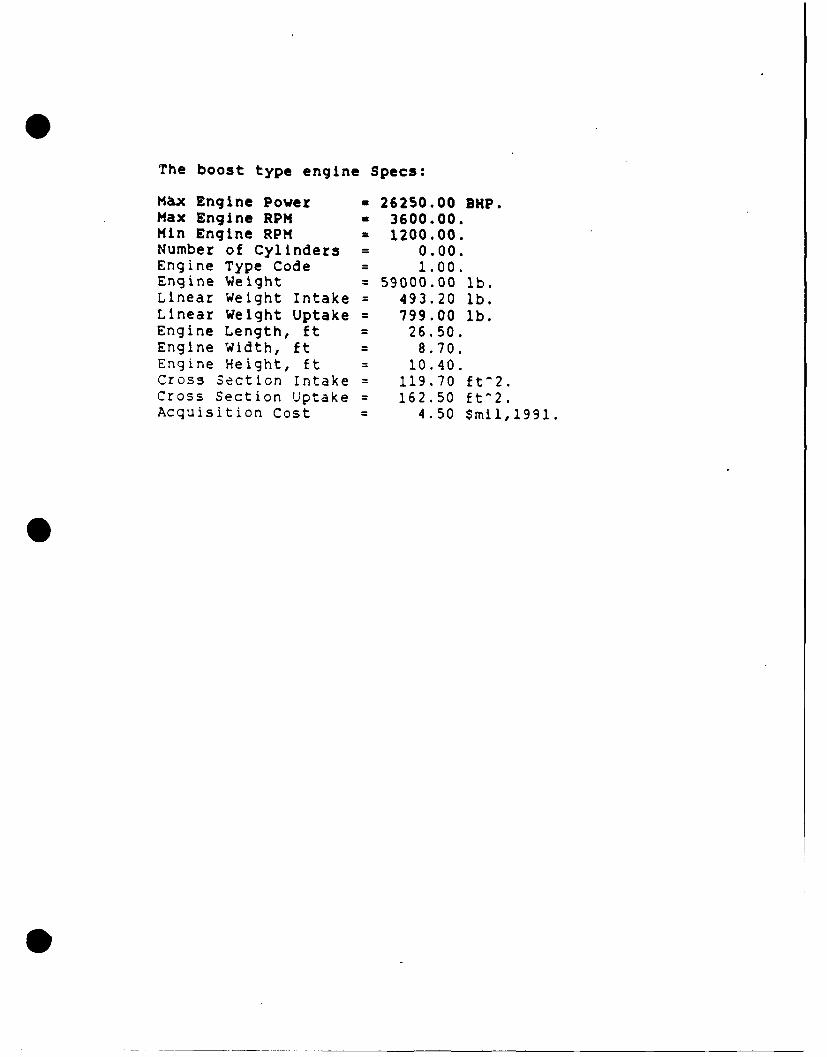
The boost type engine Specs:
Max Engine Power = 26250.00 BHP.Max Engine RPM = 3600.00.Min Engine RPM = 1200.00.Number of Cylinders a 0.00.Engine Type Code 1.00.Engine Weight = 59000.00 lb.Linear Weight Intake = 493.20 lb.Llnear Weight Uptake = 799.00 lb.Engine Length, ft = 26.50.Engine Width, ft = 8.70.Engine Height, ft = 10.40.Cross Section Intake = 119.70 ft-2.Cross Section Uptake 162.50 ft^2.Acquisition Cost = 4.50 Smil,1991.
exitSelect one of the four propulsion options.1 Mechanical Drive.2 Electric Drive.3 Mechanical with Electric Hybrid drive.4 Multiple Dispersed WaterJets.1Select the number of propulsors used for cruise.
1 One propulsor.2 Two propulsors.3 Three propulsors.
2Select the desired mechanical transmission options.
1 Epicyclic on each shaft.2 LTDR on each shaft.3 LTDR with reversing mechanism on each shaft.1The following questions are used to determine the enginetype(s] and alignments to operate the propulsion system.Note: if you choose the LM-2500 for boost, you will also begiven the opportunity to select an alternativeengine type for cruise.If you choose one of the other boost engine types,it will be assumed that your selected boost enginetype will be used for both cruise and boost operation.
Select one of the boost engine types.1 LM-2500 Gas Turbine2 ICR Gas Turbine3 PC 4.2 Diesel,16 cyl rated at 26060 HP.
Select one of the cruise engine types.0 NONE1 ICR Gas Turbine2 PC 4.2 Diesel3 PC 2.6 Diesel
0Select the total number of LM-2500 enginesused during maximum boost operation.2 Two3 Three4 Four3Select the total number of LM-2500 engines usedduring cruise operation.1 One2 Two3 Three4 Four
1Will PDSS be driven off any of the gas turbineoutput shafts.
0 NO1 Yes1Select the total number of pdss units desired.I One pdss unit.2 Two pdss units.3 Three pdss units.4 Four pdss units.3
Your selections are summarized as follows:
# Cruise Propulsors= 1 # Boost Propulsors = 3Propulsor Type z CRP Hybrid Trans Type = NoneTransmission Type a Mech XMission per shaft a EpicyclicCruise Eng Type a none Boost Eng Type z LM-2500Total # boost eng Total # boost eng
used for cruise - 1 used for boost - 3Total # cruise eng Total # cruise eng
used for cruise - 0 used for boost - 0PDSS flag setting z YES Number of PDSS * 3
Select an option:1 Run the program with your selected propulsion system.2 Reselect the propulsion system."3 Quit the program.
1Enter the following in decimal format.
Enter the cruise EHP:9360Enter the cruise QPC:.718Enter the cruise transmission efficiency:.96Enter the cruise propulsor RPM:89.0Enter the gear ratio:22.4
Number of engines used for cruise = 1.0HP per PDSS = 1693.04 BHPK34_BHP-per eng = 1693.04 BHPavg endur bhpper eng = 16630.37 BHPuncorrect sfcper eng = 0.49099 LB/HP/HRpropulsion f factor = 1.0400Tail Pipe Allowance = 1.020pct of endurance time w/bleed = 0.500avgendur fuel rate = 0.53616 LB/HP/HRThe elec avg sfc = 0.76595 LB/HP/HR.
The electric fuel wt = 282.8 LTONS.The propulsion fuel wt = 899.1 LTONS.
The Total Fuel Weight = 1182.0 LTONS.
The cruise type engine Specs:
Max Engine Power = 26250.00.Max Engine RPM = 3600.00.Min Engine RPM = 1200.00.Number of Cylinders = 0.00.Engine Type Code = 1.00.Engine Weight - 59000.00 lb.Linear Weight Intake z 493.20 lb.Linear Weight Uptake = 799.00 lb.Engine Length, ft = 26.50.Engine Width, ft 2 8.70.Engine Height, ft 10.40.Cross Section Intake = 119.70 ftW2.Cross Section Uptake = 162.50 ftW2.Acquisition Cost a 4.50 $mil,1991.
The boost type engine Specs:
M&x Engine Power = 26250.00 SHP.Max Engine RPM a 3600.00.Min Engine RPM = 1200.00.Number of Cylinders = 0.00.Engine Type Code = 1.00.Engine Weight = 59000.00 lb.Linear Weight Intake = 493.20 lb.Linear Weight Uptake = 799.00 lb.Engine Length, ft = 26.50.Engine Width, ft = 8.70.Engine Height, ft = 10.40.Cross Section Intake = 119.70 ft-2.Cross Section Uptake = 162.50 ft^2.Acquisition Cost = 4.50 $mil,1991.
C:\TC>tcSelect one of the four propulsion options.1 Mechanical Drive.2 Electric Drive.3 Mechanical with Electric Hybrid drive.4 Multiple Dispersed Waterjets.1Select the number of propulsors used for cruise.
1 One propulsor.2 Two propulsors.3 Three propulsors.
2Select the desired mechanical transmission options.
1 Epicyclic on each shaft.2 LTDR on each shaft.3 LTDR with reversing mechanism on each shaft.4 LTDR on each shaft with cross-connect.2The following questions are used to determine the enginetypels) and alignments to operate the propulsion system.Note: if you choose the LH-2500 for boost, you will also begiven the opportunity to select an alternativeengine type for cruise.If you choose one of the other boost engine types,it will be assumed that your selected boost enginetype will be used for both cruise and boost operation.
Select one of the boost engine types.1 LM-2500 Gas Turbine2 ICR Gas Turbine3 PC 4.2 Diesel,16 cyl rated at 26060 HP.
Select one of the cruise engine types.0 NONE1 ICR Gas Turbine2 PC 4.2 Diesel3 PC 2.6 Diesel
0Select the total number of LM-2500 enginesused during maximum boost operation.2 Two3 Three4 Four4Select the total number of LM-2500 engines usedduring cruise operation.1 One2 Two3 Three4 Four
2Will PDSS be driven off any of the gas turbineoutput shafts.
0 NO1 Yes
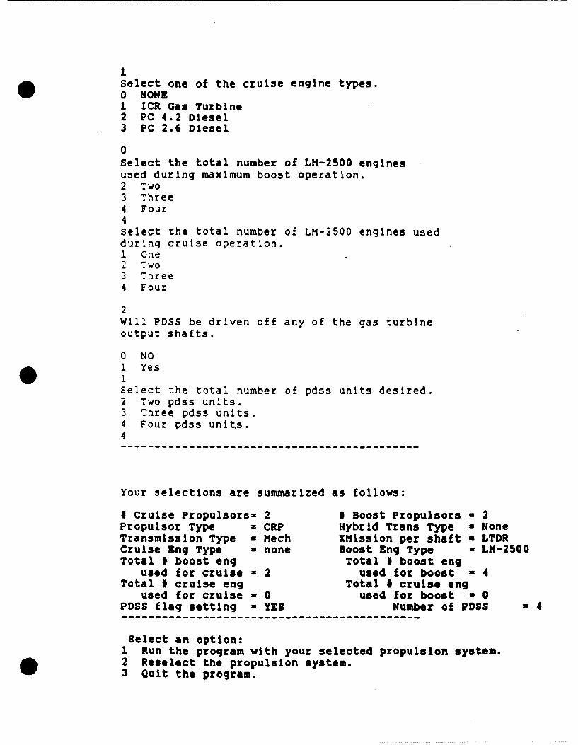
* 1Select the total number of pdss units desired.2 Two pdss units.3 Three pdss units.4 Four pdss units.4
Your selections are summarized as follows:
I Cruise Propulsors- 2 1 Boost Propulsors - 2Propulsor Type a CRP Hybrid Trans Type a NoneTransmission Type = Mech XHission per shaft a LTDRCruise Eng Type - none Boost Eng Type a LH-2500Total I boost eng Total # boost eng
used for cruise - 2 used for boost a 4Total # cruise eng Total # cruise eng
used for cruise = 0 used for boost = 0PDSS flag setting a YES Number of PD8= 4
Select an option:I Run the program with your selected propulsion system.2 Reselect the propulsion system.3 Quit the program.
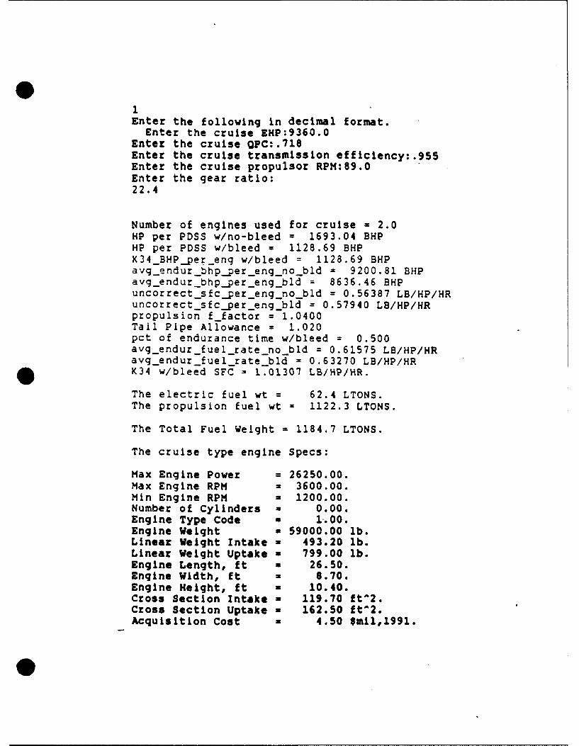
Enter the following in decimal format.Enter the cruise EHP:9360.0
Enter the cruise Qpc:.718Enter the cruise transmission efficiency:.955Enter the cruise propulsor RPM:89.0Enter the gear ratio:22.4
Number of engines used for cruise = 2.0HP per PDSS w/no-bleed = 1693.04 BHPHP per PDSS w/bleed = 1128.69 BHPK34 BHPpereng w/bleed = 1128.69 BHPavg_endurbhpper-eng_nobld = 9200.81 BHPavgqendur bhpper eng bld = 8636.46 BHPuncorrectsfcper engno bld = 0.56387 LB/HP/HRuncorrect sfcper eng bld = 0.57940 LB/HP/HRpropulsion f factor = 1.0400Tail Pipe Allowance = 1.020pct of endurance time w/bleed = 0.500avg endur fuel rate no bld = 0.61575 LB/HP/HRavgendur fuelrate_bld = 0.63270 LB/HP/HRK34 w/bleed SFC = 1.01307 LB/HP/HR.
The electric fuel wt = 62.4 LTONS.
The propulsion fuel wt = 1122.3 LTONS.
The Total Fuel Weight = 1184.7 LTONS.
The cruise type engine Specs:
Max Engine Power = 26250.00.Max Engine RPM = 3600.00.Min Engine RPM = 1200.00.Number of Cylinders = 0.00.Engine Type Code a 1.00.Engine Weight a 59000.00 lb.Linear Weight Intake a 493.20 lb.Linear Weight Uptake w 799.00 lb.Engine Length, ft a 26.50.Engine Width, ft a 8.70.Engine Height, ft a 10.40.Cross Section Intake a 119.70 ftV2.Cross Section Uptake a 162.50 ftW2.Acquisition Cost z 4.50 $mil,1991.
0
The boost type engine Specs:
Max Engine Power - 26250.00 BHP.Max Engine RPM a 3600.00.Min Engine RPM - 1200.00.Number of Cylinders = 0.00.Engine Type Code = 1.00.Engine Weight = 59000.00 lb.Linear Weight Intake = 493.20 lb.Linear Weight Uptake = 799.00 lb.Engine Length, ft = 26.50.Engine Width, ft = 8.70.Engine Height, ft = 10.40.Cross Section Intake = 119.70 ft^2.Cross Section Uptake = 162.50 ft-2.Acquisition Cost = 4.50 $mil,1991.