An exergy-based framework for evaluating environmental impact Adam P. Simpson * , Chris F. Edwards Stanford University, Department of Mechanical Engineering, Stanford, CA 94305, USA article info Article history: Received 25 July 2010 Received in revised form 7 December 2010 Accepted 17 January 2011 Available online 27 January 2011 Keywords: Exergy Exergy analysis Reference state Dead state free energy Environmental change Environmental impact abstract The analysis framework introduced in this paper utilizes the recognition that exergy is a form of envi- ronmental free energy to provide a fundamental basis for valuing environmental interactions inde- pendent from their secondary impacts (e.g., global warming, photochemical smog). In order to extend exergy to analyze environmental interactions, modifications are required to the traditional representa- tion of the environment and definition of the dead state used in technical exergy analysis. These are accomplished through a combination of logical extensions and use of non-equilibrium thermodynamic principles. The framework is comprised of two separate components: (1) environmental exergy analysis and (2) anthropocentric sensitivity analysis. Environmental exergy analysis is based on fundamental thermodynamic principles and analysis techniques. It extends the principles of technical exergy analysis to the environment in order to quantify the locations, magnitudes, and types of environmental impactdstate change, alteration of natural transfers, and destruction change. Anthropocentric sensitivity analysis is based on the concepts of anthropocentric value and anthropocentric sensitivity. It enables the results of environmental exergy analysis to be interpreted for decision making, but at the expense of introducing some subjectivity into the framework. A key attribute of the framework is its ability to evaluate and compare the environmental performance of energy systems on a level playing field, regardless of the specifics of the systemsdresources, by-products, sizes, time scales. Ó 2011 Elsevier Ltd. All rights reserved. 1. Introduction With the supply of conventional energy resources being depleted at their fastest rates, and the environmental impacts of their use better understood, there is an increasing desire to develop and employ alternative energy technologies that lessen depen- dence on these resources and reduce environmental impact. This leads to the question: Which alternative energy technologies should we pursue? In order to answer this question, the potential technologies need to be compared on a level playing field based on their environmental performance. There currently exist several analysis techniques for evaluating the environmental performance of energy systems. These can be cate- gorized as being based on species, economics, or thermodynamics. Species-based techniques measure the environmental perfor- mance of energy systems based on the amount of a particular species emitted by a system. The species of interest are typically those that have been identified as causing adverse environmental consequences. Example species include oxides of nitrogen (NO x ), sulfur dioxide, carbon dioxide, and chlorofluorocarbons (CFCs). The emission of these particular species are monitored because of identified adverse environmental consequencesdphotochemical smog, acid rain, global warming, and ozone depletion. Species- based techniques typically communicate an energy system’s envi- ronmental performance by the mass of a species emitted per unit of desired output (e.g., kg-CO 2 /MWh elec ). Extensions have been made to species-based techniques for comparing a range of species on the basis of their potential to cause a common environmental consequence. The most prominent of these extensions is the use of Global Warming Potentials (GWPs) by government agencies such as the U.S. Environmental Protection Agency (EPA) and the Intergovernmental Panel on Climate Change (IPCC). GWPs provide a measure of a species’ potential to cause global warming relative to that of carbon dioxide. The details of and standard methods used to measure GWPs are defined by the IPCC [1]. When GWPs are employed to measure an energy system’s environmental performance, the results are communicated through a mass of carbon-dioxide-equivalent emission per unit of desired output (e.g., kg-CO 2 -eq./MWh elec ). Economics-based techniques measure environmental perfor- mance by assigning a monetary value to the undesirable outputs from energy systems that are known to cause adverse environ- mental consequences. In economics, the adverse environmental * Corresponding author. Tel.: þ1 650 725 2012; fax: þ1 650 723 1748. E-mail addresses: [email protected], [email protected](A.P. Simpson). Contents lists available at ScienceDirect Energy journal homepage: www.elsevier.com/locate/energy 0360-5442/$ e see front matter Ó 2011 Elsevier Ltd. All rights reserved. doi:10.1016/j.energy.2011.01.025 Energy 36 (2011) 1442e1459
Transcript
lable at ScienceDirect
Energy 36 (2011) 1442e1459
Contents lists avai
Energy
journal homepage: www.elsevier .com/locate/energy
An exergy-based framework for evaluating environmental impact
Adam P. Simpson*, Chris F. EdwardsStanford University, Department of Mechanical Engineering, Stanford, CA 94305, USA
a r t i c l e i n f o
Article history:Received 25 July 2010Received in revised form7 December 2010Accepted 17 January 2011Available online 27 January 2011
Keywords:ExergyExergy analysisReference stateDead state free energyEnvironmental changeEnvironmental impact
0360-5442/$ e see front matter � 2011 Elsevier Ltd.doi:10.1016/j.energy.2011.01.025
a b s t r a c t
The analysis framework introduced in this paper utilizes the recognition that exergy is a form of envi-ronmental free energy to provide a fundamental basis for valuing environmental interactions inde-pendent from their secondary impacts (e.g., global warming, photochemical smog). In order to extendexergy to analyze environmental interactions, modifications are required to the traditional representa-tion of the environment and definition of the dead state used in technical exergy analysis. These areaccomplished through a combination of logical extensions and use of non-equilibrium thermodynamicprinciples. The framework is comprised of two separate components: (1) environmental exergy analysisand (2) anthropocentric sensitivity analysis. Environmental exergy analysis is based on fundamentalthermodynamic principles and analysis techniques. It extends the principles of technical exergy analysisto the environment in order to quantify the locations, magnitudes, and types of environmentalimpactdstate change, alteration of natural transfers, and destruction change. Anthropocentric sensitivityanalysis is based on the concepts of anthropocentric value and anthropocentric sensitivity. It enables theresults of environmental exergy analysis to be interpreted for decision making, but at the expense ofintroducing some subjectivity into the framework. A key attribute of the framework is its ability toevaluate and compare the environmental performance of energy systems on a level playing field,regardless of the specifics of the systemsdresources, by-products, sizes, time scales.
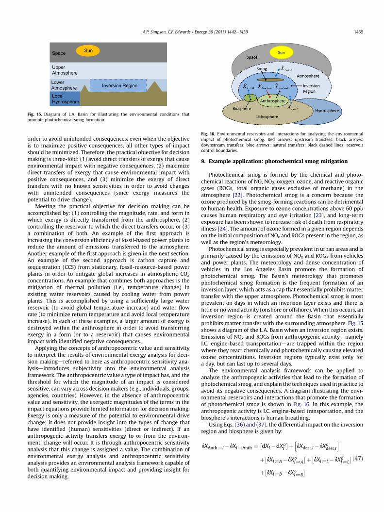
� 2011 Elsevier Ltd. All rights reserved.
1. Introduction
With the supply of conventional energy resources beingdepleted at their fastest rates, and the environmental impacts oftheir use better understood, there is an increasing desire to developand employ alternative energy technologies that lessen depen-dence on these resources and reduce environmental impact. Thisleads to the question: Which alternative energy technologiesshould we pursue? In order to answer this question, the potentialtechnologies need to be compared on a level playing field based ontheir environmental performance.
There currentlyexist several analysis techniques for evaluating theenvironmental performance of energy systems. These can be cate-gorized as being based on species, economics, or thermodynamics.
Species-based techniques measure the environmental perfor-mance of energy systems based on the amount of a particularspecies emitted by a system. The species of interest are typicallythose that have been identified as causing adverse environmentalconsequences. Example species include oxides of nitrogen (NOx),
sulfur dioxide, carbon dioxide, and chlorofluorocarbons (CFCs). Theemission of these particular species are monitored because ofidentified adverse environmental consequencesdphotochemicalsmog, acid rain, global warming, and ozone depletion. Species-based techniques typically communicate an energy system’s envi-ronmental performance by themass of a species emitted per unit ofdesired output (e.g., kg-CO2/MWhelec).
Extensions have been made to species-based techniques forcomparing a range of species on the basis of their potential to causea common environmental consequence. The most prominent ofthese extensions is the use of GlobalWarming Potentials (GWPs) bygovernment agencies such as the U.S. Environmental ProtectionAgency (EPA) and the Intergovernmental Panel on Climate Change(IPCC). GWPs provide a measure of a species’ potential to causeglobal warming relative to that of carbon dioxide. The details of andstandard methods used to measure GWPs are defined by the IPCC[1]. When GWPs are employed to measure an energy system’senvironmental performance, the results are communicatedthrough a mass of carbon-dioxide-equivalent emission per unit ofdesired output (e.g., kg-CO2-eq./MWhelec).
Economics-based techniques measure environmental perfor-mance by assigning a monetary value to the undesirable outputsfrom energy systems that are known to cause adverse environ-mental consequences. In economics, the adverse environmental
A.P. Simpson, C.F. Edwards / Energy 36 (2011) 1442e1459 1443
consequences are referred to as environmental damages, and thecost assigned to these damages are referred to as an environmentalexternal cost. There are several methods employed to define whatis considered environmental damage and to prescribe an environ-mental external cost. A detailed review of these methods isprovided by Riva and Trebeschi [2]. Economists and policy makerstypically use the environmental external cost of an energy systemas a measure of its environmental performance. The environmentalexternal cost of an energy system can be combined with its internalcost (i.e., internalized) to provide a measure of the system’s realcost. It is often argued that the real cost of an energy systemprovides a more appropriate measure of economic performancethan internal cost when comparing energy system options [2,3].
A significant shortcoming of species- and economic-basedanalysis techniques is that the environmental transfers of concernmust be identified as being undesirable a priori of the analysis.Environmental transfers from an energy system are typically onlyidentified as being undesirable after they have caused some type ofadverse consequence. Neither technique is capable of evaluatingthe environmental performance of an energy systemwithout priorknowledge of the system’s environmental transfers causingadverse consequences. Furthermore, both techniques only provideproxy measures of environmental performance. They do notprovide the ability to evaluate the environmental change driven byan energy system’s environmental interactions (upstream anddownstream environmental transfers).
Thermodynamics-based techniques employ thermodynamicconcepts to evaluate and measure the environmental performanceof energy systems. The noteworthy thermodynamics-based anal-ysis techniques are: Life Cycle Assessment (LCA), CumulativeExergy Consumption (CEC), Cumulative Exergy Extraction from theNatural Environment (CEENE), Extended Exergy Accounting (EEA),and Emergy Analysis. All of these analysis techniques extend thecontrol boundary of an energy system and the time scale of theanalysis to include all components and processes required tosupport the system over its entire life (often referred to as “cradle-to-grave” analysis). The key differences between the five tech-niques are in how they value the inputs and outputs of a system,and how they measure environmental performance.
Life Cycle Assessment is essentially an extension of first law-analysis. It tracks the mass and energy of inputs and outputs of anenergy system over its entire life (not including capital and labor).The energy of physical inputs and outputs are typically measuredbased on their heating value (lower or higher). LCA measures theenvironmental performance of an energy system through the totalamount of natural resource energy required to produce a desiredproduct, and through the total amount of emissions produced bythe system. The former is typically communicated via a net energyvalue (e.g., LHVnet ¼ LHVdesired products�LHVresource inputs) or anoverall first-law efficiency (e.g., LHVdesired products/LHVinputs), andthe later is typically communicated via the mass of emissions perunit of desired product (e.g., kg-CO2,total/MWhelec). The methodsand applications used in LCA are described by the U.S. EPA [4].
Cumulative Exergy Consumption tracks the embodied exergy ofinputs to an energy system over its entire life (again, not includingcapital and labor). The embodied exergy of an input ismeasured by thesum of the fossil and nuclear resource exergy that went into its pro-duction (e.g., the embodied exergy of a kg of steel is the amount ofresource exergy consumed during its production). CEC measures theenvironmental performance of energy systems through the total am-ount of embodied exergy required to produce a desired output (i.e.,through thedesiredoutput’s cumulative, orembodied, exergycontent).CEC communicates environmental performance via an overall exergyefficiency, which is referred to as the cumulative degree of perfection.The details and applications of CEC are described by Szargut et al. [5,6].
Cumulative Exergy Extraction from the Natural Environmentextends the embodied exergy concept used in CEC to include theexergy of renewable resource inputs, such as solar radiation, wind,and geothermal exergy. CEENE measures the environmentalperformance of energy systems through the total amount ofembodied exergy (measured through the CEC approach) andrenewable exergy required to produce a desired output (i.e.,through the total amount of exergy removed from the naturalenvironment). Dewulf et al. [7] describe the details and applica-tions of CEENE.
Extended Exergy Accounting tracks the extended exergycontent of all inputs and outputs of an energy system over its entirelife, including capital and labor. The extended exergy content ofnon-capital and non-labor inputs is calculated through theembodied exergy methods used in CEC. The extended exergycontent of capital is calculated by assigning an exergy value toa unit of a country’s currency based on the country’s gross domesticproduct (GDP) and the total amount of natural resource exergyconsumed by the country in a given year (e.g., MJ/$GDP). Theextended exergy content of labor is calculated by assigning anexergy value to a hour of work (a “man-hour”) based on the totalamount of natural resource exergy consumed by a person tosupport 1 h of work (e.g., MJ/man-hour). EEA assigns an extendedexergy content to an energy system’s undesired outputs (e.g.,emissions, waste) based on the extended exergy content of allinputs that would be required to reduce their exergy (thermo-mechanical and chemical) to zero. EEA measures the environ-mental performance of energy systems through the total amount ofextended exergy input to a system in order to produce a desiredoutput and reduce the exergy of undesired outputs to zero. Thedetails and applications of EEA are described by [8e14].
EmergyAnalysis tracks the solar emergyof all inputs to anenergysystemover its entire life, including capital and labor. Solaremergy isdefined as the total amount of solar exergy directly or indirectlyrequired to produce a givenflow, and ismeasured in solar equivalentjoules (seJ). The solar emergy of capital is calculated by assigninga solar emergy value to a unit of a country’s currency based on thecountry’s GDP and the total amount of solar exergy incident on andsolar emergy consumed by the country over a given year (e.g., seJ/$GDP). The solar emergy of labor is calculated by assigning a solaremergy value to a man-hour based on the total amount of solaremergy consumed by a person to support 1 h of work (e.g., seJ/man-hour). EmergyAnalysismeasures theenvironmental performanceofanenergysystemthroughvariousmetrics basedon the total amountof solar emergy required to support the production of a desiredoutput. The development, details, and applications of EmergyAnalysis are described by [12,15e17].
Emergy and EEA analysis can be viewed as overall performanceanalysis techniques because of their inclusion of capital and labor.They essentially roll environmental and economic performancecomponents into one unit of measuredsolar emergy and extendedexergy content, respectivelydin order to internalize all transfers toand from an energy system. This is similar to the economicapproach of measuring environmental damages through an envi-ronmental external cost and internalizing this cost to form the realcost of an energy system or energy product.
While all of the existing environmental analysis techniques haveindividual merit, they do not provide a fundamental basis for eval-uating environmental impact, or environmental change. Even thosetechniques that use exergy analysis as a tool for tracking energyflows into,within, and froman energy systemmiss the essential factthat it is the free energy of those flows to and from the system thatcauses environmental change. And with the additional realizationthat exergy is environmental free energy comes recognition that thestudyof exergybalances as applied to the environment aswell as the
Fig. 1. Closed system in communication with a thermo-mechanical reservoir withwork extraction. The thermostat and barostat control heat and boundary-worktransfers to maintain temperature T and pressure P inside the system.
A.P. Simpson, C.F. Edwards / Energy 36 (2011) 1442e14591444
traditional engineering system is required to provide a fundamentalassessment of environmental impact.
This paper presents an analysis framework based on thermo-dynamic principles and analysis techniquesdnamely exergy andexergy analysisdfor evaluating the environmental impact ofenergy systems. The framework utilizes the recent recognition thatexergy is a form of free energy to extend themodels and techniquesused in technical exergy analysis to the environment. This exten-sion enables the locations, magnitudes, and types of environmentalimpact caused by energy systemsdboth upstream and down-streamdto be evaluated on a level playing field across the range ofpossible resources used (renewable and non-renewable) andoutputs produced (desired and undesired) over the time scales inwhich energy systems operate.
The following section provides a discussion of the connectionbetween exergy and free energy, and a proof that exergy is a form offree energy and therefore a measure of the ability to drive change.Next, exergy analysis is applied to a well-defined model system todemonstrate its application outside of an energy system for thepurpose of evaluating environmental change. The following twosections discuss key concepts that are needed in order to effectivelyextend exergy analysis to the natural environmentdnamely, revi-sions to the traditional understanding of a reference state, and themodel representation of the environment used in technical exergyanalysis. Next, the ways in which energy systems interact with andimpact the environment are discussed. The following sectionoutlines the application of environmental exergy analysis forevaluating the environmental impact of energy systemsdor moregeneral anthropogenic activity. The paper then introduces theconcept of anthropocentric sensitivity and discussing its role inenvironmental impact analysis and decision making. The paperconcludes by applying that analysis framework to a real worldenvironmental problem to illustrate the analysis technique’s abilityto both evaluate environmental impact and provide guidance fordecision making.
2. Environmental free energy
Exergy is defined as the maximum amount of work that can beextracted from a resource relative to its environment. The termsresource and environment are italicized to emphasis both theirimportance and interdependence. A resource refers to any energyaccumulation or energy flow that has the potential to do workrelative to its environment. The environment refers to the portionsof the natural environment that enable work to be extracted froma resource because it acts as a thermal, mechanical, and/or chemicalreservoir to the resource. A resource has the ability to do workbecause it is out of equilibrium with its environment. Work cantheoretically be extracted fromany system that is out of equilibrium,and the maximum amount of work is realized when the systemequilibrates reversibly. Exergy is an extension of this principle inwhich the system is comprised of a resource and the environment.
Exergy is derived by applying the First and Second Laws ofthermodynamics to a resource in communication with its envi-ronment and calculating the reversible (i.e., maximum) amount ofwork that can be extracted as equilibrium is reached. Reversibilityrequires that the resource transfer heat at the environmentaltemperature, boundary work at the environmental pressure, andexchange environmental species at their environmental chemicalpotentials. In traditional derivations of exergy, reversible interac-tions are realized by modeling the environmental surroundings asa large reservoir with fast internal transport such that its intensivestate does not change (i.e., as a thermodynamic reservoir). A deri-vation of exergy that models the environmental surroundings inthis manner is provided in Appendix A.
This section presents an alternative derivation of exergy similarto a derivation of Gibbs free energy in order to introduce the ideathat exergy is a form of free energydspecifically, environmentalfree energy. All forms of free energy measure the maximumamount of work that can be extracted from a non-equilibriumsystem constrained to equilibrate under specified interaction con-straintsde.g., constant temperature and pressure for Gibbs freeenergy, and constant temperature and volume for Helmholtz freeenergy. Exergy is, by definition, the maximum amount of work thatcan be extracted from a system comprised of a resource and itsenvironment constrained to equilibrate at the conditions of theenvironment. Therefore, exergy is the free energy of a resourcerelative to its environment.
To show this, a derivation of Gibbs free energy is presented first.Consider a closed system of fixed temperature and pressure that isinitially separated into two regions by a partition, with regions Aand B on either side of the partition. The individual regions areinitially in internal equilibrium and at the same temperature andpressure, but they are not in chemical equilibrium. The temperatureand pressure of the system are held constant through heat andboundary-work transfers with an external thermo-mechanicalreservoir controlled by a thermostat and barostat, respectively.Since the system is initially out of equilibrium, there exists a drivingpotential that can theoretically be extracted as work. A diagram ofthis closed system in communication with a thermo-mechanicalreservoir with work extraction is shown in Fig. 1.
The maximum amount of work that can be extracted from thesystem is derived by applying the First and Second Laws of ther-modynamics to the control boundary around the system. The diff-erential expressions of the First and Second Laws for the system are:
dU ¼ dQ � dWb � dW (1)
dS ¼ dQT
þ dSgen (2)
Combining Eqs. (1) and (2) and employing the definition ofboundary work, dWb ¼ PdV , yields a expression for the differentialamount of work extracted from the system.
dW ¼ �dU � PdV þ TdS� TdSgen (3)
The maximum amount of work is realized when interactionsbetween the regions occur reversibly (i.e., no entropy generation).Therefore, the expression for the maximum work that can beextracted from the system is:
dWmax ¼ �dU � PdV þ TdS
¼ �dðU þ PV � TSÞT ¼ const:P¼ const:
h� dG (4)
( ) ,, ,o o i oT P N ( ), , kT P N
W
Thermodynamic Reservoir
Thermostat, To
Barostat , Po
Chemostat , μ i,o
QbW iN
Environment Resource
δ δ δδ
Fig. 2. Open system in communication with a thermodynamic reservoir. The ther-mostat, barostat, and chemostat control heat, boundary work, and matter transfers,respectively, to maintain the state of the environment region (To, Po, and mi;o). Subscripti designates environmental species and subscript k designates species initially presentin the resource region, which can include both environmental species (i) and non-environmental species (j).
A.P. Simpson, C.F. Edwards / Energy 36 (2011) 1442e1459 1445
As shown in the above equation, the maximum work that can beextracted from a closed, isothermal, isobaric system is equal to thedifferential change in the Gibbs function of the system. Themaximum amount of work that can be extracted from the system iscalculated by integrating Eq. (4) from the initial state to the finalequilibrium state of the system. This yields:
Wmax ¼ �DG ¼ �Ginitial � GEQ
�(5)
The above equation shows that the maximum amount of work thatcan be extracted from a closed, isothermal, isobaric system is equalto the change in the Gibbs function from the initial state to the finalstate of the system. In other words, the change in Gibbs function fora closed, isothermal, isobaric system between its initial state andfinal equilibrium state is free to be extracted as work. Hence theterm Gibbs free energy.
The same approach used to derive Gibbs free energy can beapplied to other closed systems with different interactionconstraints. It can be shown that the maximum amount of workthat can be extracted from a closed system constrained to equili-brate at constant temperature and volume is its change in Helm-holtz function (�DA, or Helmholtz free energy), at constant entropyand volume it is the change in internal energy ð�DUÞ, and atconstant entropy and pressure it is the change in enthalpy ð�DHÞ.Therefore, for closed, isentropic, isochoric systems, the internalenergy is a form of free energy, and for closed, isentropic, isobaricsystems, the enthalpy is a form of free energy.
To show that exergy is a form of free energy, consider an opensystem in communication with an external thermodynamic reser-voir. The system is comprised of two regions, with one called an“environment” and the other a “resource”, initially separated bya partition. Each region is initially in internal equilibrium, but not inmutual equilibrium. The environment region is in communicationwith the thermodynamic reservoir controlled by a thermostat,barostat, and a series of selective chemostatsdone for each envi-ronmental species (i). The thermostat, barostat, and chemostatscontrol heat, boundary work, and matter transfers, respectively, tomaintain the environment region at its initial thermodynamicstatedTo, Po, and mi;o. Since the regions are initially out of equilib-rium, there exists a driving potential that can theoretically beextracted as work. The maximum amount of work that can beextracted from the system is realized as it equilibrates reversibly.The final equilibrium state of the system is equal to the state of theenvironment region since it is maintained constant. A diagram ofthis open system in communication with a thermodynamic reser-voir with work extraction is shown in Fig. 2.1
The maximum amount of work that can be extracted from thesystem is derived by applying the First and Second Laws to thecontrol boundary around the system. The differential expressions ofthe First and Second Laws for the system are:
dU ¼ dQ � dWb þXi
hi;odNi � dW (6)
dS ¼ dQTo
þXi
si;odNi þ dSgen (7)
where hi;o and si;o are themolar enthalpy and entropy of the speciesi in the environment region. Combining Eqs. (6) and (7) andemploying the definition of boundary work, dWb ¼ PodV , yields anexpression for the differential work extracted from the system.
1 The environment and resource regions of this example shown in Fig. 2 areanalogous to regions A and B of the pervious example shown in Fig. 1.
dW ¼ �dU � PodV þ TodSþPi
�hi;o � Tosi;o
�dNi
�TodSgen(8)
The maximumwork is realized when the interactions between thereservoirs occur reversibly (i.e., no entropy generation). Therefore,the expression for the maximum differential amount of work thatcan be extracted from the system is:
dWmax ¼ �dU � PodV þ TodSþXi
mi;odNi (9)
The maximum amount of work is calculated by integrating Eq. (9)from the initial state of the system to the mutual equilibriumstate of the two regions, which is equal to the state of the envi-ronment region. In order to perform this integration, the inexactdifferential for the transfer of moles must be converted to an exactdifferential. This can be accomplished by considering the reversibletransformation of all non-environmental species (j) present in theresource region (non-environmental resource species) to speciespresent in the environment region (i) through the followingreaction:�
Rj�: aAþ bB/cC þ dD;
with extensive extent of reaction; xj;
aA/� bBþ cC þ dD
njAj/Pini;jAi
(10)
where nj is the stoichiometric coefficient for the non-environmentalresource species (j), and ni;j is the stoichiometric coefficient for theenvironmental species (i) used or created by the transformation ofnon-environment resource species.2 The species balances forenvironmental species and non-environmental resource speciesare:
dNi ¼ dNi þXj
ni;jdxj (11)
dNj ¼ �njdxj (12)
2 As indicated by Eq. (10), the sign correction used for ni;j is such that productspecies are taken as positive and reactant species are negative.
Fig. 3. Model system comprised of a heat engine located within a local environment.
A.P. Simpson, C.F. Edwards / Energy 36 (2011) 1442e14591446
Combining Eqs. (11) and (12) through the differential extent ofreaction yields an exact differential expression for the transfer ofmoles of environmental species between the environment regionand the thermodynamic reservoir:
dNi ¼ dNi þXj
�ni;j=nj
�dNj (13)
Combining the above expression and Eq. (9) yields an exactdifferential equation for the maximum amount of work:
dWmax ¼ �dU � PodV þ TodSþPimi;odNi
þPimi;o
Pj
�ni;j=nj
�dNj
(14)
Integration of the above equation from the initial state of thesystem to the state of environment region yields an expression forthe maximum amount of work that can be extracted from thesystem.3
Wmax ¼ ðU þ PoV � ToSÞ �Pimi;oNi
�Pj
"Pimi;o�ni;j=nj
�#Nj
(15)
Equation (15) was derived by applying the same approach used toderive Gibbs free energy, and represents the free energy of an opensystem comprised of two regions in communication with a ther-modynamic reservoir that maintains the state of one of the regionsconstant. The equation is equivalent to the equation of internalexergy derived in Appendix A. Therefore, the free energy ofa system comprised of a resource and an environmental reservoirconstrained to equilibrate at the state of the environment is equalto the exergy of the resource. In other words, exergy is the envi-ronmental free energy of a resource.
The connection between exergy and free energy is significantbecause of the connection between free energy and the potential todrive change. In order for a system to have free energy, the systemmust be out of equilibrium, and all systems that are out of equi-librium have the potential to drive change [18]. Therefore, all formsof free energy inherently measure the ability to drive changedalbeit with differing interaction constraints. The free energy ofa system can be extracted from the system as work, or if no work isextracted, change will occur within the system. When a system iscomprised of a resource and the environment, the exergy of theresource provides a measure of its potential to drive change in theenvironment. Recognizing this fact enables the exergy of transfersto and from the environment to be used as a measure of thepotential to drive change in the environment. In technical (ortraditional) exergy analysis, exergy is tracked within an energysystem to quantify the locations, magnitudes, and types of lostwork within an energy systemdexergy destruction within thesystem or transfers of unused exergy from the system. The sameanalysis techniques can be extended outside of the energy systemto within the environment to quantify the locations, magnitudes,and types of environmental change caused by an energy system.
3. Extending exergy analysis to the environment
To demonstrate the application of exergy analysis for quanti-fying the locations, magnitudes, and types of environmentalchange caused by an energy system, a small-scale energy systemoperating within a well-defined, local environment is analyzed
3 The details of this integration are provided in Appendix A.
first. The purpose of applying exergy analysis to a well-definedenvironment is to introduce and gain comfort with the techniquesandmodels used to quantify environmental change before applyingenvironmental exergy analysis to the natural environmentdacomplex system. The techniques and models used to quantify thechange this small-scale energy system drives in its local environ-ment can be extended to large-scale energy systems operatingwithin the natural environment, as is shown in the followingsections.
A diagram of the model system considered here is shown inFig. 3. The energy system is an insulated heat engine, and the localenvironment is comprised of a hot copper block, an open watertank, a rigid, closed laboratory, and a large reservoir called the“surroundings”. The heat engine cross-connects the copper blockand water tank, which are both located within the laboratory. Theinitial states of the environmental reservoirs are specified in thefigure. The composition of the laboratory and surroundings isengineering air with an initial relative humidity of 50%, and thewater in the tank is pure (i.e., no dissolved air). The surroundingsare considered as being a thermodynamic reservoir, and eachenvironmental reservoir is in local thermodynamic equilibrium.
The natural and anthropogenic energy transfers within themodel system during heat engine operation are shown in Fig. 4.Natural transfers are the result of the environmental reservoirsbeing out of equilibrium, and anthropogenic transfers are caused bythe operation of the heat engine. The natural transfers consideredin this analysis include the transfers of heat from the copper block(C) to the laboratory, heat and matter from the water tank (W) tothe laboratory, and heat from the laboratory (L) to the surroundings(S). The anthropogenic transfers considered in this analysis includethe upstream transfer of heat to the heat engine (H) and thedownstream transfers of water between the water tank and heatengine.4 Implied by the limited number of transfers shown in thefigure, are the assumptions that the heat engine is perfectly insu-lated, the laboratory is perfectly rigid and closed, the water in thewater tank remains pure, and there is negligible heat conductionalong the pipes connecting the heat engine and water tank.
To measure the exergy of the transfers and individual reservoirs,an appropriate reference state must be chosen. A reference state, or“dead state”, can be defined by a reference temperature (Tref), pres-sure (Pref), and chemical potentials for all relevant species in thesystem ðmi;ref Þ. For this isolated model system, the state of thesurroundings provides a reference state fromwhich the exergy (i.e.,driving potential) of the transfers and reservoirs can be measured
4 Strictly speaking, the engine is a “heat-matter” engine because the resource isheat but entropy is rejected to the environment in the form of matter. A true heatengine uses heat as both the resource and means of entropy rejection.
Fig. 4. Natural and anthropogenic transfers in the model system during heat engineoperation. Red arrows: upstream transfers; black arrows: downstream transfers; bluearrows: natural transfers; black dashed lines: control boundaries. (For interpretation ofthe references to colour in this figure legend, the reader is referred to the web versionof this article.)
A.P. Simpson, C.F. Edwards / Energy 36 (2011) 1442e1459 1447
since it is modeled as a thermodynamic (“infinite”) reservoir.5 Sincecopper isnotpresent in the surroundings, a reference state for copperis required to quantify its chemical exergy. An appropriate chemicalreference state for copperwouldbe thatof solid copper,whichmeansthat the copper block only has thermo-mechanical exergy.
The change that the heat engine drives in its environment can bequantified by tracking the exergy of transfersdnatural andanthropogenicdwithin the environment. In the absence of heatengine operation (the anthropogenic activity), exergy would benaturally transferred between the environmental reservoirsddriving natural state change and natural exergy destruction withinthe environment. The relationship between the natural exergytransfers, state changes, and destructions is shown through theexergy balances for the individual reservoirs:
½C� : dXoC/L ¼ �dXo
C � dXodest;C (16)
½W� : dXoW/L ¼ �dXo
W � dXodest;W (17)
½L� : dXoC/L þ dXo
W/L ¼ dXoL þ dXo
dest;L (18)
½S� : dXoL/S ¼ dXo
S þ dXodest;S (19)
where the superscript o designates values in the absence ofanthropogenic activity.6
Equations (16)e(19) show that, at any instant, the net exergytransferred to a reservoir is equivalent to the sum of the exergychange and exergy destruction within the reservoir. The equationscan be interpreted as showing that the natural exergy transfersbetween the reservoirs are the drivers of natural state change andnatural exergy destruction.
During heat engine operation, state change and exergydestruction is caused by both anthropogenic and natural transfers.The relationship between the natural and anthropogenic exergy
5 Only the reservoirs shown in the Fig. 3 are considered in this analysis. If themodel system was considered to be within the terrestrial environment, a moreappropriate reference state would be the mutual stationary state of the terrestrialenvironment. The concept of a mutual stationary state is discussed in Section 4.
6 Implicit in the differential impact equations are the surface and volume inte-grals that correspond to the control boundaries shown in Fig. 4. All exergy transfersare integrated over the surface of the control boundary they cross (e.g.,dXC/H ¼ dt
R_X00C/HdSC , where _X
00is exergy transfer rate per surface area, and SC is
the surface area of the copper block), and all exergy changes and destructions areintegrated over the volume enclosed by the control boundary (e.g.,dXC ¼ dtðR _X
000C dVCÞ, dXdest;C ¼ dt
R_X000dest;CdVC , where _X
000is exergy change or
destruction rate per volume, and VC is the volume of the copper block).
transfers, state changes, and destructions is again shown throughthe exergy balances for the individual reservoirs:
As in Eqs. (16)e(19), the above equations show that, at any instant,the net exergy transferred to a reservoir is equivalent to the sum ofthe exergy change and exergy destruction within the reservoir.However, due to the anthropogenic transfers, the natural transfer,exergy change, and exergy destruction terms in the above equa-tions are different from those in Eqs. (16)e(19).
The change due to the heat engine can be shown by taking thedifference between the exergy balances for the individual reser-voirs during heat engine operation and in the absence of the heatengine. Doing this and rearranging the equations yields:
½C� : dXC/H ¼ � �dXC � dXoC�� hdXdest;C � dXo
dest;C
i� �dXC/L � dXo
C/L� ð24Þ
½W� : dXH#W ¼ �dXW � dXoW�þ hdXdest;W � dXo
dest;W
iþ �dXW/L � dXo
W/L� ð25Þ
½L� : �dXC/L � dXoC/L
�þ �dXW/L � dXoW/L
� ¼ �dXL � dXo
L�
þhdXdest;L � dXo
dest;L
iþ �dXL/S � dXo
L/S� ð26Þ
½S� : �dXL/S�dXoL/S
� ¼ �dXS�dXoS�þhdXdest;S�dXo
dest;S
i(27)
where # represents a net transfer (e.g., dXH#WhdXH/W�dXW/H).
Equations (24) and (25) show that, at any instant during heatengine operation, the net exergy directly transferred to the copperblock and water tank (upstream or downstream of the workextraction process) is equivalent to the sum of the differencesbetween the exergy change, exergy destruction, and net exergytransferred from the reservoirs during the activity and in theabsence of the activity. The equations can be interpreted as showingthat direct transfers of exergy caused by the heat engine are thedrivers of environmental change in the copper block andwater tank,and the types of change are state change, destruction change, andalterations of natural transfers. In order for no change to occur, theanthropogenic transfers must have zero exergydwhich means thatno work would be produced from the heat engine.
Equations (26) and (27) show that, at any instant during heatengine operation, the difference between the net exergy naturallytransferred to the laboratory and surroundings during the activityand in the absence of the activity is equivalent to the sum of thedifferences between the exergy change, exergy destruction, and netexergy naturally transferred from the reservoirs during the activityand in the absence of the activity.
To illustrate the correspondence between this model problemand an actual energy system operating within the natural envi-ronment, consider the geothermal power plant illustrated in Fig. 5.The geothermal power plant and its environmental reservoirs
Surface Water Reservoir
Geothermal Reservoir (Hot Rock)
Atmosphere
Upper Lithosphere
Space
Geothermal Power Plant
Fig. 5. Illustration of a geothermal power plant.
( , , , B B k B B U V N
( ) , , , A A i A A T P
( ) , , , A A i A AB T P
Initial Equilibrium States Final Equilibrium State
µ
µ
(
Fig. 6. Isolated, two-reservoir system of differing thermodynamic states with reservoirA being large relative to reservoir B such that it is modeled as a thermodynamicreservoir (left). Final state of the system after equilibrium is reached, which is equal tothe initial intensive state of reservoir A (right). Subscript i designates species initiallypresent in reservoir A and subscript k designates species initially present in reservoir B,which can include both reservoir A species (i) and non-reservoir A species (j).
( ) , , , B B k B B U V N
( ) , , , A A k A A U V N
( ) , , , ref ref i ref AB T P
Initial Equilibrium States Final Equilibrium State
µ
Fig. 7. Isolated, two-reservoir system of differing thermodynamic states with bothreservoirs of similar size (left). Final state of the system after equilibrium is reached(right). Subscript i designates species present at equilibrium and subscript k designatesspecies initially present in reservoirs A and B, which can include both equilibriumspecies (i) and non-equilibrium species (j).
A.P. Simpson, C.F. Edwards / Energy 36 (2011) 1442e14591448
shown in the figure are analogous to the heat engine and its localenvironmentdthe power plant is analogous to the heat engine, thegeothermal reservoir to the copper block, the surface water reser-voir to the water tank, the atmosphere to the laboratory, and spaceto the surroundings. The same analysis techniques used to quantifythe local environmental change driven by the heat engine can beapplied to the geothermal power plant to quantify the change itdrives in the natural environment. However, in order to make thisextension, an appropriate reference state must be defined tomeasure the exergy (i.e., driving potential) of the power plant’senvironmental interactions, the environmental reservoirs, and thenatural environmental transfers. This requires revisions to thetraditional understanding and definition of a reference state (ordead state) and a model representation of the natural environ-mentdthese are the topics of the next two sections, respectively.
4. Defining reference states
As discussed in Section 2, the maximum amount of work thatcan be extracted from a non-equilibrium system under specificinteraction constraints is the system’s free energy. If the system iscomprised of a resource and its environment, then the system’s freeenergy is equal to the exergy of the resource. In order to define theexergy, or free energy, of a system, a reference state is required. Areference state of a system provides a datum from which the workpotential, or change potential, of the system is measured. When thesystem reaches the reference state, no work can be produced from,or no change can occur within, the system. An appropriate refer-ence state for a system depends on the specifics of the system. Toillustrate this, several example systems are considered.
First, consider a two-reservoir system of differing thermody-namic states and initially restrained from interaction, as shown inFig. 6. Reservoir A is sufficiently large with respect to reservoir Bsuch that it can be modeled as a thermodynamic reservoir (i.e., ashaving a fixed intensive state). Each reservoir is initially in internalequilibrium, but not in mutual equilibrium. The free energy of thejoint system is measured by themaximum amount of work that canbe extracted as the system equilibrates reversibly. Since reservoir Ais large with respect to reservoir B, the final (i.e., equilibrium)intensive state of the system is the same as the original state ofreservoir A, as shown in the figure. Therefore, the free energy of thesystem is measured as the work potential of reservoir B relative toreservoir A, which serves as the reference state. The free energy ofthis two-reservoir system is given by:
Wmax;System ¼Wmax;B ¼ UB þ PAVB � TASB
�Xi
mi;ANi;B �Xj
"Xi
mi;A
nijnj
!#Nj;B ð28Þ
where all extensive properties are evaluated at the initial state ofreservoir B, all intensive properties are evaluated at the state of
reservoir A (which is constant), subscripts i and j refer to speciespresent and not present in reservoir A, respectively, and nj and nijare the stoichiometric coefficients for the reaction of species. Adetailed derivation of Eq. (28) is presented in Appendix A.
Equation (28) is equivalent to the traditional equation forinternal exergy derived in Appendix A if the state of reservoir A isdefined as the state of the reference environment (i.e., if TA ¼ To,PA ¼ Po, and mi;A ¼ mi;o for all i). Considering reservoir A to be anenvironmental reservoir, then the free energy of the system is equalto the exergy of reservoir B relative to its its environment(Wmax;System ¼ Wmax;B ¼ XB).
The two-reservoir system just considered involved a thermo-dynamic reservoir that, when considered to be an environmentalreservoir, provides a reference state from which the exergy of theother reservoir could be defined. The inherent principle of exer-gyda measure of the ability to produce work or to drive changedisnot limited to systems involving a large environmental reservoir. Toillustrate this, consider a two-reservoir systemwith both reservoirsconsidered to be of similar size, as shown in Fig. 7. Since thereservoirs are initially out of equilibrium, each reservoir hasthe potential to drive change relative to the other reservoir. Thepotential to drive change vanishes when the two reservoirs reachequilibrium. The mutual equilibrium state of the system definesa reference state fromwhich the exergy of the individual reservoirsand therefore the joint system can bemeasured. In other words, themutual equilibrium state is a kind of “dead state” from which nochange can occur. The exergy of the composite system and indi-vidual reservoirs relative to the mutual equilibrium statedreferredto here as the reference statedis given by:
XSystem ¼ XA þ XB (29)
XA ¼ UA þ Pref VA � Tref SA �Pimi;ref Ni;A
�Pj
"Pimi;ref
�nijnj
�#Nj;A
(30)
Fig. 8. Driven, two-reservoir system in thermal stationary states at the same pressure,but with differing compositions (left). Final non-equilibrium stationary state of thesystem after chemical equilibrium is reached (center). Temperature profiles of theinitial and final stationary systems (right). Subscript i designates species present atequilibrium and subscript k designates species initially present in reservoirs A and B,which can include both equilibrium species (i) and non-equilibrium species (j).
A.P. Simpson, C.F. Edwards / Energy 36 (2011) 1442e1459 1449
XB ¼ UB þ Pref VB � Tref SB �Pimi;ref Ni;B
�Pj
"Pimi;ref
�nijnj
�#Nj;B
(31)
where the properties of the reference state are considered to beknown (or knowable) constants.7
This same approach to defining the dead stateda mutualequilibration of isolated systemsdcan be used to define the deadstate for any number of interacting reservoirs of any size. A similarapproach may be taken for defining the dead state of open/drivensystems. To illustrate this, consider a two-reservoir system drivenby heat transfer between two large thermal reservoirs, as shown inFig. 8. Energy is transferred to the system (reservoirs A and B) froma high-temperature thermal reservoir, and energy is transferredfrom the system to a low-temperature thermal reservoir. Theindividual reservoirs are initially in thermal stationary states at thesame pressure, but with differing compositions (and thereforethermal conductivities). The initial stationary temperature distri-bution of the system might then be shown in the figure.8 Since thereservoirs initially have different compositions, each reservoir hasthe potential to drive change relative to the other. The potential todrive change vanishes when the reservoirs reach chemical equi-librium, and a final (non-equilibrium) thermal stationary state isformed. The final state defines a reference “state” from which thefree energy, or exergy, of the individual reservoirs and system canbe measureddsimilar to the mutual equilibrium state for isolated,multi-reservoir systems.
The final, or mutual, stationary state is reached when theentropy generation ratewithin the system is minimized [19]. This isknown as the theorem of Minimum Entropy Production, andapplies to all driven systems that are in the linear regime (i.e., it isnot limited to systems driven by thermal flows).9 For this system, ifboth reservoirs are gaseous, and gravitational and buoyancy forcesare negligible, the final stationary state will have uniform compo-sition and pressure with a linear temperature distribution, asshown in the figure. The final stationary state for the systemd
referred to here as the reference statedis defined by its pressure(Pref), chemical potentials (mi;ref ), and temperature as a function ofposition ðTðyÞref Þ. In general, the reference state for a driven, multi-reservoir system can be defined by its intensive properties asfunctions of position (e.g., Tref ¼ TðxÞ, Pref ¼ PðxÞ, andmi;ref ¼ miðxÞ for all i, where x is a general position vector).
The problem that remains is possible ambiguity due to inho-mogeneity of the reservoirs in space and/or time. In fact, theexample just considered immediately begs the question: At whichaltitude y should the value of Tref be chosen? There are twopotential answers to this question. The firstdapplicable in the casewhere the open/driven system has the potential to be decoupledfrom its driving reservoirsdis that altitude which corresponds tothe subsequent, isolated equilibration of the non-equilibriumsystem. The seconddapplicable when the driving forces are
7 Equations (29)e(31) can also be derived by considering a three-reservoirsystem composed of the two environmental reservoirs of similar size, and a “large”environmental reservoir that has the same state as the mutual equilibrium state ofthe other two reservoirs. The state of the “large” reservoir acts as a reference statefrom which the exergy of the composite system and other two reservoirs can bedefined. Therefore, by analogy, the mutual equilibrium state of the two-reservoirsystem shown in Fig. 7 serves as a fiducial state for defining exergy.
8 A stationary temperature TðyÞ implies that mean heat flow is uniform; other-wise there will be an accumulation or depletion of energy within the system, whichwould require a time-dependent temperature profile [19].
9 Linear regime refers to thermodynamic flows (e.g., heat transfer, diffusion,chemical reactions, electrical conduction) that are linear functions of their drivingforces (e.g., temperature, concentration, chemical affinity, electric field).
maintaineddis the altitude at which the anthropogenic energyconversion system will be situated. Note that if the conversionsystem interacts at two (or more) altitudes so as to take advantageof the inhomogeneity, then the appropriate viewwould be to breakthe reservoirs apart into separate regions, each with an appropri-ately defined state, such that mutual equilibration of reservoirs wasagain the basis for defining the reference state. In the present case,this would result in use of an energy-mean temperature (and cor-responding altitude) as being the appropriate reference. Similararguments can be made with respect to the temporal variations inreservoir state, whether they be daily, seasonal, or of some longerepoch. In each case, the appropriate definition of reference statefollows from the state at which further work extraction is notpossible by virtue of some form of mutual equilibration.
5. An Expanded model of the environment
In technical exergy analysis, the environment is typicallymodeled based on the properties of the atmospheredwith modi-fications for solid mineral and liquid substancesdas a large reser-voir with fast internal relaxation such that its intensive state doesnot change (i.e., a thermodynamic reservoir)[5]. This type ofreference environment simplifies exergy calculations because thefinal (equilibrium) intensive state of a resource and its environmentis equal to the state of the reference environment. It also impliesthat any exergy transferred from an energy system to the envi-ronment only causes exergy destruction within the environment(i.e., no environmental state change). This traditional representa-tion of the environment is sufficient for calculating exergy asa measure of maximum work when performing technical exergyanalysis. However, in order to effectively extend the principles ofexergy and exergy analysis to analyze environmental change,a more detailed representation is required. This can be accom-plished by taking a macroscopic view of the natural environment.
The terrestrial environment can bebrokendown into threemajorenvironmental reservoirs: atmosphere, hydrosphere, and litho-sphere. Theatmosphere is a reference environmentof theair (similarto the traditional atmosphere-based reference environment), thehydrosphere is a reference environment of the oceans, and thelithosphere is an aggregated reference environment of the earth’scrust and surfacewater (e.g., lakes, rivers, snowpack). Depending onthe specifics of the energy system and type of analysis, the majorreservoirs may need to be further broken down into sub-reservoirs,or minor reservoirs, in order to provide a suitable representation ofthe environment. For example, when analyzing a power plant thatuses a lake for cooling water, the lake should be broken apart fromthe lithosphere and modeled as a separate, finite reservoir.
Space
Atmosphere
HydrosphereLithosphere
Sun
FossilResources
Geothermal
Biosphere
High K.E.
Surface Water
NuclearResources
Fig. 9. Model representation of the natural environment.
11 The distinction between environmental and resource reservoirs depends on the
A.P. Simpson, C.F. Edwards / Energy 36 (2011) 1442e14591450
The terrestrial environmental reservoirs serve as large reservoirsfor resources to be converted into exergetic products (e.g., work,electricity, commercial fuels, heat).10 A review of the global exergyresources available for work production on Earth is presented byHermann [20]. Global exergy resources can be categorized as eitherexergy accumulations or exergy flows. The majority of the work onEarth is produced from accumulated fossil and nuclear resources.Fossil resources are the by-products of plant and animalmatter thathave been converted by the Earth’s natural exergy flows andprocesses into higher quality resources (e.g., crude oil, natural gas,coal). They are typically locatedwithin the lithosphere and naturallysegregated from communication with the other major reservoirs.Nuclear resources are from the origin of the universe and are locatedwithin the lithosphere and hydrosphere. Both resources are typi-cally considered non-renewablednuclear resources because theyare finite, and fossil resources because the time scales over whichtheyare replenished are significantly longer than the anthropogenictime scales inwhich theyare extracted and consumed. Formodelingpurposes, fossil and nuclear resources are represented as individualresource reservoirs located within their respective terrestrial envi-ronmental reservoirs.
The Earth’s second largest accumulated resource after nuclearmatter is the thermal energy in its mantle and core, which iscalled crustal thermal energy. Crustal thermal energy is derivedfrom the decay of nuclides in the Earth’s interior, the originalinternal energy from the gravitational collapse of the Earth, and toa lesser extent, the dissipation of tidal forces [20]. The Earth’scrustal thermal energy provides a relatively constant flow ofexergy through the lithosphere in the form of heat. The quality ofthe heat that reaches the surface of the lithosphere is, in mostcases, too low for it to be economically converted to work.Therefore, work is typically produced by intervening in the naturalexergy flow deep within the lithosphere. The locations of heatextraction are commonly referred to as geothermal reservoirs.Exergy extracted from geothermal reservoirs is typically consid-ered a renewable resource; however, this is only true when theexergy is extracted in a manner such that there is sufficient timefor natural replenishment to take place. For modeling purposes,geothermal reservoirs are represented as resource reservoirslocated within the lithosphere.
The Earth’s largest resource flow is solar radiation generatedfrom fusion reactions occurring within the sun. The sun is a finiteresource, however, the solar radiation produced is typicallyconsidered a renewable resource because of the relatively rapidrate of replenishment on Earth. Solar radiation travels throughspace, which acts as a medium for transmitting radiation to theEarth, as well as a sink for the Earth’s re-radiation. For modelingpurposes, the sun is represented as a resource reservoir and space isincluded as an environmental reservoir.
Other major resource flows include wind, tides, waves, andrivers. All of these occur within the terrestrial environmentalreservoirs and are typically considered renewable resources due tothe relatively short time scales over which they are regenerated. Inorder tomodel work extraction from these resources, the terrestrialenvironmental reservoir in which the flow is located must bebroken apart into a resource reservoir and an environmentalreservoir. For example, when analyzing work extraction fromwind,the atmosphere must be broken apart into high and low kineticenergy reservoirsdwith the high kinetic energy reservoir modeledas the resource and the low kinetic energy reservoir modeled as theenvironment.
10 For the sake of brevity, the term work is used to represent all exergeticproducts.
The environmental and resource reservoirs can be representedgraphically, as shown in Fig. 9.11 The environmental reservoirs arenaturally out of equilibrium with one another, and therefore havethe potential to drive change. As a result, exergy is naturallytransferred between the reservoirs, driving natural state changeand natural exergy destruction. These natural interactions, and theresulting natural changes and destructions, occur on a wide-rangeof time scales and magnitudes. Natural interactions enable andsupport life on Earth. Living organisms (e.g., animals, plants,fungus, micro-organisms) exist in all three terrestrial environ-mental reservoirs. For modeling purposes, living organisms arerepresented in their own region, referred to here as the biosphere.The pathways for natural interactions are depicted in the figure bythe locations of the reservoirs. For example, the atmosphereinteracts with the lithosphere, hydrosphere, biosphere, and space.
In order to measure the exergy (i.e., driving potential) of naturalinteractions and environmental reservoirs, an environmentalreference state is required. As shown in Section 4, the exergy (i.e.,environmental free energy) of multi-reservoir systems can bemeasured relative to either the system’s mutual equilibrium state ifit is isolated, or the system’s mutual stationary state if it is driven.Since the Earth is a driven, multi-reservoir system, in theory itsmutual stationary state defines an environmental reference statefrom which the exergy of reservoirs and interactions can bemeasured. Any stationary state can be defined by its intensiveproperties as functions of position. For the purposes of environ-mental exergy analysis, we choose to define the environmentalreference state (a stationary state) using a mean temperature (Tref),pressure (Pref), and chemical potential for all relevant species ðmi;ref Þ.
Now that a more detailed representation of the natural envi-ronment and a reference state for measuring the exergy of envi-ronmental reservoirs and natural transfers have been established,the ways in which humans interact with and impact the environ-ment can now be discussed.
6. Anthropogenic interactions and environmental impact
Human activity occurs within the natural environment ina region referred to as the anthrosphere. The anthrosphere isdefined as the part of the natural environment physically modifiedby humans and used for their activities [21]. The size of theanthrosphere depends on the specifics of the activity. For example,
relative sizes of the reservoirs. For example, if a small amount of air is introduced intoa large fossil resource reservoir (e.g., a natural gas reservoir), the air is the resourcebecause it has the potential to produce work relative to its fossil resource surround-ings. For the sake of brevity, environmental and resource reservoirs will be referred toas environmental reservoirs. When necessary, the distinction is made explicit.
Space
HydrosphereLithosphere
Sun
Natural
Gas
Heat
Cooling
Water
Anthrosphere
AirNoise
Exhaust Gas
Fig. 10. Example of the first conversion pathway. Red arrows: upstream interactions;black arrows: downstream interactions. (For interpretation of the references to colourin this figure legend, the reader is referred to the web version of this article.)
Space
Hydrosphere Lithosphere
Sun
Heat
Radiation
Biosphere
Anthrosphere
Surface-Incident
Solar Radiation
Fig. 11. Example of the second conversion pathway. Red arrows: upstream interac-tions; black arrows: downstream interactions. (For interpretation of the references tocolour in this figure legend, the reader is referred to the web version of this article.)
A.P. Simpson, C.F. Edwards / Energy 36 (2011) 1442e1459 1451
when analyzing the extraction of natural gas from an undergroundreservoir, the anthrosphere extends into the lithosphere to thelocation of extraction within the reservoir.
There are two main pathways by which energy systems withinthe anthrosphere convert resources to work: (1) by cross-con-necting environmental reservoirs, and (2) by intervening in naturalexergy flows. Both conversion pathways interact with the envi-ronment. Each pathway’s environmental interactions can bebroken down into upstream and downstream interactions.Upstream interactions are defined as exergy transfers to or from theanthrosphere, or alterations of natural exergy transfers within theanthrosphere, in order to extract and convert a resource to work.Downstream interactions are defined as energy transfers from theanthrosphere as a consequence of the conversion process.
An example of the first conversion pathway is the extraction andconversion of natural gas into electricity using air from the atmo-sphere and cooling water from a surface water reservoir. A diagramillustrating the environmental interactions of this example energysystem is shown in Fig. 10. The upstream interactions include thetransfers of natural gas from the gas reservoir, air from the atmo-sphere, and water from the surface water reservoir.12 The down-stream interactions include the transfers of cooling water to thesurface water reservoir, and exhaust gases, heat, and noise to theatmosphere. Both upstream and downstream interactions transferenergy between the anthrosphere and connected environmentalreservoirs. The electricity produced by the conversion processremains in the anthrosphere until final consumption by an elec-trical device.
An example of the second conversion pathway is the conversionof surface-incident solar radiation into electricity via photovoltaic(PV) cells. A diagram illustrating the environmental interactions ofthis example energy system is shown in Fig. 11. The anthrosphere islocated at the intersection of the lithosphere, biosphere, andatmosphere. The activity intervenes in the natural exergy flow ofsolar radiation above the lithosphere and biosphere, and as a resultof the conversion process, transfers heat and radiation to theatmosphere. The surface-incident solar radiation altered withinthe anthrosphere is considered the upstream interaction, and thetransfers of heat and radiation from the anthrosphere are thedownstream interactions.
In the absence of anthropogenic activity, natural interactionswould occur without disturbancedexergy would be naturally
12 An example of an upstream interaction involving a transfer from the anthro-sphere to an environmental reservoir is the injection of CO2 into an oil reservoir forthe purpose of enhancing oil recovery.
transferred between environmental reservoirs driving natural statechange and natural exergy destruction within the reservoirs. Thenatural exergy transfers, state change, and destruction set a baselinefrom which any changes caused by anthropogenic activity can bemeasured. Any changes to the states of, natural exergy transfersbetween, or exergy destructionwithin the environmental reservoirscaused by anthropogenic activity is defined as environmentalimpact. This definition of environmental impact is agnostic to theconsequences of the impact, and it is not limited to a specific type ofimpact (e.g., atmospheric state change) or consequence (e.g., globalwarming).
A diagram illustrating the drivers of environmental impact andthe terminology used to describe environmental interactions andimpacts is shown in Fig. 12. Environmental impact begins withanthropogenic activity. The environmental interactions of anthro-pogenic activity may involve upstream or downstream transfers(e.g., transfers of natural gas to the anthrosphere or emissions fromthe anthrosphere), which are called direct transfers, or upstreamalterations of natural transfers (e.g., alteration of surface incidentsolar radiation within the anthrosphere), which are called directalterations of natural transfers. Direct transfers and direct alter-ations of natural transfers have exergy, and therefore the potentialto cause environmental impact (i.e., drive environmental change).Direct transfers impact the environmental reservoirs to or fromwhich the transfers occur (e.g., gaseous emissions to the atmo-sphere impact the atmosphere; natural gas removal from anunderground reservoir impacts the reservoir), and direct alter-ations of natural transfers impact the environmental reservoirsfromwhich the alterations occurs (e.g., intercepting solar radiationnormally incident on the lithosphere impacts the lithosphere).Environmental impact caused by direct transfers and direct alter-ations of natural transfers is referred to as direct impact.
Direct impact may cause alterations of natural transfersbetween environmental reservoirs (e.g., direct changes to theamount of CO2 in the atmosphere may cause alterations of naturaltransfers of CO2 between the atmosphere and hydrosphere), ortransfers between environmental reservoirs that did not occurprior to the anthropogenic activity (e.g., direct changes to theamount of fertilizer on the surface of the lithosphere may causefertilizer run-off into the hydrosphere). Transfers and alterations ofnatural transfers caused by direct impact are called indirecttransfers and indirect alterations of natural transfers, respectively.Indirect transfers and indirect alterations of natural transfers haveexergy, and therefore the potential to cause environmental impact.Environmental impact caused by indirect transfers and indirectalterations of natural transfers is referred to as indirect impact.
As illustrated in Fig. 12, the drivers of environmentalimpactddefined as changes to the states of, exergy transfers
Anthropogenic
Activity
Direct
Transfers
Direct
Impact
Indirect
Impact
Direct Alterations
of Natural
Transfers
Indirect Transfers
Indirect Alterations
of Natural
Transfers
Fig. 12. Environmental impact drivers and terminology.
Fig. 13. Model representation of the conversion of a geothermal resource to electricity.Black arrows: downstream transfers; red arrows: upstream transfers; blue arrows:natural exergy transfers; black dashed lines: reservoir control boundaries. (For inter-pretation of the references to colour in this figure legend, the reader is referred to theweb version of this article.)
A.P. Simpson, C.F. Edwards / Energy 36 (2011) 1442e14591452
between, or exergy destruction within environmental reser-voirsdare the transfers and alterations of natural transfers causedby an anthropogenic activity. The potential for transfers and alter-ations of natural transfers to drive environmental impact ismeasured by their exergy (i.e., environmental free energy). Asshown in the next section, the locations, magnitudes, and types ofenvironmental impact caused by an anthropogenic activity can bequantified by applying exergy analysis to the environment usingthe same approach demonstrated in Section 3 to quantify theimpact of the heat engine on its local environment.
13 As in the laboratory-scale example, implicit in the differential impact equationsare surface and volume integrals that correspond to the control boundaries shownin Fig. 13.
7. Environmental exergy analysis
To demonstrate the application and utility of exergy analysis forquantifying environmental impact, the geothermal power plantintroduced in Section 3 is considered. A diagram illustrating theenvironmental interactions of such a plant is shown in Fig. 13. Asshown in the figure, activities in the anthrosphere cross-connecta geothermal reservoir located within the lithosphere to a surfacewater reservoir. The upstream interactions include exergy transfersfrom the geothermal reservoir (heat) and surface water reservoir(cooling water), and the downstream interactions include exergytransfers to the surface water reservoir (coolant return) andatmosphere (heat and noise). Both the upstream and downstreaminteractions are direct transfers between the anthrosphere andenvironmental reservoirs. Also shown in the figure are the naturalexergy transfers between the environmental reservoirs.
The environmental reservoirs can be categorized based on theircommunication with the anthrosphere. Reservoirs in directcommunication with the anthrosphere are referred to as a reser-voirs, and reservoirs not in direct communication with theanthrosphere are referred to as b reservoirs. The a reservoirs in thisexample include the geothermal and surface water reservoirs, andthe b reservoirs include the atmosphere, lithosphere, biosphere,hydrosphere, and space. The control boundaries for the individualreservoirs are shown by the dashed lines in Fig. 13.
In the absence of anthropogenic activity, exergy would benaturally transferred between the environmental reservoirs. Therelationship between the natural exergy transfers, state change,and destruction is shown through the exergy balances for the a andb reservoirs:
½ai� :Xj
dXoaj#ai
þXk
dXobk#ai
¼ dXoaiþ dXo
dest;ai(32)
½bk� :Xl
dXobl#bk
þXm
dXoam#bk
¼ dXobk
þ dXodest;bk
(33)
where the superscript o again designates values in the absence ofanthropogenic activity, the indices j and k refer to a and b reservoirsin communication with reservoir ai, and indices l and m refer tob and a reservoirs in communication with reservoir bk.13 All exergyvalues are measured relative to the environmental reference statediscussed in Section 5. The above exergy balances show that, at anyinstant, the net exergy transferred to a reservoir is equivalent to thesum of the exergy change and exergy destruction withinthe reservoir. The equations can be interpreted as showing that thenatural exergy transfers between the reservoirs are the drivers ofnatural state change and natural exergy destruction.
During anthropogenic activity, state change and exergydestruction is caused by both anthropogenic and natural transfers.The relationship between the natural and anthropogenic exergytransfers, state changes, and destructions is again shown throughthe exergy balances for the a and b reservoirs:
dXAnth#aiþP
jdXaj#ai þ
PkdXbk#ai
¼ dXai þ dXdest;ai
(34)
½bk� :Xl
dXbl#bkþXm
dXam#bk¼ dXbk
þ dXdest;bk(35)
As in Eqs. (32) and (33), the above equations show that, at anyinstant, the net exergy transferred to a reservoir is equivalent to thesum of the exergy change and exergy destruction within thereservoir. However, due to the anthropogenic transfers, the naturaltransfer, exergy change, and exergy destruction terms in the aboveequations are different from those in Eqs. (32) and (33).
The environmental impact that anthropogenic activity has ona given a reservoir can be shown by taking the difference betweenthe exergy balances for the reservoir with anthropogenic activityand in the absence of the activity. Doing this and rearranging theequation yields:
dXAnth#ai¼hdXai � dXo
ai
iþhdXdest;ai
� dXodest;ai
iþP
j
hdXai#aj � dXo
ai#aj
iþP
k
hdXai#bk
� dXoai#bk
i (36)
A.P. Simpson, C.F. Edwards / Energy 36 (2011) 1442e1459 1453
The equation shows that, at any instant during anthropogenicactivity, the net exergy directly transferred to an a reservoir(upstream or downstream of the conversion process) is equivalentto the sum of the differences between the exergy change, exergydestruction, and net exergy transferred from the a reservoir duringthe activity and in the absence of the activity. The equation can beinterpreted as showing that direct transfers are the drivers ofenvironmental impact on a reservoirs, and the types of directimpact on a reservoirs are state change, destruction change, andalterations of natural transfers.14
The environmental impact that anthropogenic activity has ona given b reservoir can be shown by taking the difference betweenthe exergy balances for the reservoir with anthropogenic activityand in the absence of the activity, and rearranging the equation.Doing this for a b reservoir in communication with an a reservoiryields:
dXai#bk�dXo
ai#bk¼hdXbk
�dXobk
iþhdXdest;bk
�dXodest;bk
i
þPl
hdXbk#bl
�dXobk#bl
iþP
m
hdXbk#am
�dXobk#am
i (37)
and doing this for a b reservoir not in communication with ana reservoir yields:
dXbk#bm�dXo
bk#bm¼hdXbm
�dXobm
iþhdXdest;bm
�dXodest;bm
i
þXn
hdXbm#bn�dXo
bm#bn
i(38)
The above equations show that, at any instant during an anthro-pogenic activity, the difference between the net exergy naturallytransferred to a b reservoir during the activity and in the absence ofthe activity is equivalent to the sum of the differences between theexergy change, exergy destruction, and net exergy naturallytransferred from the b reservoir during the activity and in theabsence of the activity. The equations can be interpreted asshowing that alterations of natural transfers are the drivers ofindirect impact on b reservoirs, and the types of impact onb reservoirs are state change, destruction change, and other alter-ations of natural transfers.
Equations (36)e(38) can be referred to as the differential impactequations. They apply to any energy system categorized by the firstconversion pathwaydi.e., they are not limited to geothermalconversion processes. For energy systems categorized by thesecond conversion pathway, the above impact equations apply forall reservoirs except for a reservoirs that would have received thenatural exergy flow altered within the anthrosphere. As discussedin the previous section, direct alterations of natural transfersimpact the environmental reservoirs from which the alterationsoccur (e.g., alteration of surface-incident solar radiation impacts thelithosphere). Therefore, a reservoirs from which exergy is alteredwithin the anthrosphere are directly impacted by the exergyaltered from naturally reaching the reservoirs. The differentialimpact equation for an a reservoir from which exergy is altered isgiven by:
14 When using Eqs. (37) and (38) to quantify the impact on b reservoirs caused byindirect transfers (i.e., transfers between environmental reservoirs that did notoccur prior to the anthropogenic activity), the net exergy transferred to the reser-voir in the absence of the activity is zero (i.e., dXo
ai#bk¼ 0, dXo
bk#bm¼ 0).
dXaj/ai � dXoaj/ai
¼hdXai � dXo
ai
iþhdXdest;ai
� dXodest;ai
i
þhdXai/aj � dXo
ai/aj
iþP
k
hdXai#ak � dXo
ai#ak
i
þPl
hdXai#bl
� dXoai#bl
i(39)
The difference on the left hand side of this equation represents theamount of exergy altered within the anthrosphere from naturallybeing transferred from reservoir aj to reservoir ai (e.g., the amountof surface-incident solar radiation altered by PV cells from beingtransferred from the atmosphere, aj, to the lithosphere, ai). Thedifference can be thought of, or viewed, as a direct transfer ofexergy from aj. The equation shows that, at any instant during ananthropogenic activity, the exergy altered from reaching ana reservoir is equivalent to the sum of the differences between theexergy change, exergy destruction, and net exergy naturallytransferred from the reservoir during the activity and in theabsence of the activity. The equation can be interpreted as showingthat direct alterations of natural transfers are the drivers of envi-ronmental impact on a reservoirs fromwhich exergy is altered, andthe types of direct impact on the reservoir are state change,destruction change, and alterations of natural transfers.
As in the laboratory-scale example, the differential impactequations provide insight into the possible locations and types ofenvironmental impact caused by an anthropogenic activity. Inorder to solve for the actual locations, magnitudes, and types ofenvironmental impact, the differential impact equations must beintegrated over the interval of interestdfrom the start of theactivity to the integration time, tint. Information about the prop-erties of transfers and reservoirs is required in order to solve thedifferential impact equations. Although the natural environmentis a more complex system than the local environment in thelaboratory-scale example, the same engineering models andassumptions used to model the the laboratory’s environment andsolve its differential impact equations can be applied to thenatural environmentdchoosing appropriate control boundaries,reservoir classifications, time scales, etc. The appropriate envi-ronmental models and the amount of information required tosolve the differential impact depends on the specifics of theanthropogenic activity (e.g., power plant size, number of powerplants, time of operation) and the questions being asked of theanalysis (e.g., local impact on a water reservoir, global impact onatmosphere).
When sufficient information is known to solve the differentialimpact equations, Eqs. (36)e(39):, integration from the start of anactivity to a specified integration time (tint) yields the (integrated)impact equations.
XAnth#ai¼hXai;tint � Xo
ai;tint
iþhXdest;ai
� Xodest;ai
i
þPJ
hXai#aj � Xo
ai#aj
iþP
k
hXai#bk
� Xoai#bk
i (40)
Xai#bk�Xo
ai#bk¼hXbk;tint �Xo
bk ;tint
iþhXdest;bk
�Xodest;bk
i
þPl
hXbk#bl
�Xobk#bl
iþP
m
hXbk#am
�Xobk#am
i (41)
Xbk#bm�Xo
bk#bm¼hXbm;tint �Xo
bm;tint
iþhXdest;bm
�Xodest;bm
i
þPn
hXbm#bn
�Xobm#bn
i (42)
Fig. 14. Three reservoir system in communication with an anthropogenic activity.Black arrows: downstream transfers; blue arrows: natural transfers; black dashedlines: control boundaries. (For interpretation of the references to colour in this figurelegend, the reader is referred to the web version of this article.)
A.P. Simpson, C.F. Edwards / Energy 36 (2011) 1442e14591454
Xaj/ai � Xoaj/ai
¼hXai;tint � Xo
ai;tint
iþhXdest;ai
� Xodest;ai
iþhXai/aj � Xo
ai/aj
iþP
k
hXai#ak � Xo
ai#ak
iþP
l
hXai#bl
� Xoai#bl
i (43)
In each of the impact equation, the exergetic magnitude of thedrivers of impact (transfers or alterations of natural transfers) ona reservoir is equal to the sum of the types of impact within thereservoirdstate change, destruction change, and alterations ofnatural transfers. As shown in the equations, state change ismeasured as the difference between the exergy of a reservoirevaluated at the end of integrationwith anthropogenic activity andin the absence of the activity. The initial exergy of the reservoirswith and without activity cancel because they are equal at timezero (i.e., the beginning of the integration).
The actual locations, magnitudes, and types of environmentalimpact caused by an anthropogenic activity depend on the form(e.g., thermal, mechanical, chemical, gravitational potential, etc.),rate, and magnitude of the direct exergy transfers and alterations,and the properties and size of the environmental reservoirs. Forexample, a direct transfer of thermal exergy to an environmentalreservoir can cause different impacts than a direct transfer ofchemical exergy to the same reservoir at the same rate andmagnitude. Or, a direct transfer of chemical exergy to a smallreservoir can cause different impacts than the same direct transferto a larger reservoir with the same properties (less state change andmore destruction change).
The framework of environmental exergy analysis presented inthis section is based on fundamental thermodynamic principles.The differential impact equations derived through environmentalexergy analysis provide insight into the possible locations and typesof environmental impact, and evaluation of the impact equationsquantifies the actual locations, types, and magnitudes of environ-mental impact. As shown in the next section, the impact equationsprovide a basis for decision making.
8. Interpreting the impact equations for decision making
The impact equations can be interpreted as showing that inorder to avoid environmental impact, all direct transfers must havezero exergy. However, it is impossible to produce work in theanthrosphere without directly transferring exergy upstream ordownstream of a conversion process.15 Therefore, a practicalobjective inferred from the impact equations might be to minimizethe exergy of direct transfers, regardless of the form in which theexergy is transferred, in order to minimize the overall environ-mental impact. This approach is valid if the consequences of thetypes of impacts caused by an activity are all valued equally. On anexergetic basis, the types of impact are all valued equally. However,from an anthropocentric viewpoint, the types of impact are notlikely to be of equal value. The anthropocentric value a type ofimpact has depends on the consequences of the impact andanthropocentric sensitivity to the impact.
To introduce the concepts of anthropocentric value and sensi-tivity, consider the activity shown in Fig. 14. The activity directlytransfers exergy to an a reservoir that is in communication witha b reservoir and another reservoir called region x. The differentialimpact equation for the reservoirs are:
15 As discussed in Section 2, the potential for work extraction only exists whena system is out of equilibrium. Therefore, exergy, or free energy, must be transferredupstream or downstream of a given conversion process in order for work extractionto take place.
dXAnth/a ¼�dXa�dXo
a
�þhdXdest;a�dXodest;a
iþhdXa#b�dXo
a#b
iþhdXa#x�dXo
a#x
ið44Þ
dXa#x � dXoa#x ¼
hdXx � dXo
x
iþhdXdest;x � dXo
dest;x
i(45)
dXa#b � dXoa#b ¼
hdXb � dXo
b
iþhdXdest;b � dXo
dest;b
i(46)
The differential impact equations provide insight into the possiblelocations and types of environmental impact. To interpret theequations for decision making, a value for each type of impact mustbe assigned.
Consider the case where region x has been identified as beingsensitive to state change, such that any state change within theregion is valued as being undesirable. As shown by Eq. (45), thedriver of impact on region x is the alteration of natural transfersbetween the region and the a reservoir, and the types of impact arestate change and destruction change. With knowledge of thesensitivity to, and value of, state change within region x, the prac-tical objective is to design or choose an energy system that directlytransfers exergy to the a reservoir in a form that does not causestate change within region x. The direct exergy transfer term in Eq.(44) can therefore be viewed as the control variable, and since thedriver of state change is the alteration of natural transfers, it can beviewed as the sensitivity constraint.
The differential impact equations provide insight for designingor choosing an energy system that avoids causing state changewithin region x. There are two options for avoiding state changewithin the region: (1) directly transfer exergy in a form such thatthere is no alteration of natural transfers between the region andthe a reservoir, or (2) directly transfer exergy in a form such thatany alteration of natural transfers only cause destruction changewithin the region. Information is needed in order to know whichforms of exergy cause alterations of natural transfers between theregion and the a reservoir, and which forms only cause destructionchange. If this information is known, an energy system can bedesigned or chosen to avoid directly transferring exergy in theseforms.
In order to identify the sensitivities to a type of impact, theconsequences of the impact must inherently have some value tohumansdeither directly or indirectly. A consequence can be valuedas being negative (e.g., global warming, loss of biodiversity, adversehealth affects) or positive (e.g., global warming remediation,enhanced biodiversity, beneficial health affects). Often, the sensi-tivities to a type of impact are not identified until after the conse-quences of the impact have negatively affected humans (e.g., oceanacidification, acid rain, photochemical smog, global warming). In
Inversion Region
Local Hydrosphere
Upper Atmosphere
Space Sun
Lower Atmosphere
Fig. 15. Diagram of L.A. Basin for illustrating the environmental conditions thatpromote photochemical smog formation.
Fig. 16. Environmental reservoirs and interactions for analyzing the environmentalimpact of photochemical smog. Red arrows: upstream transfers; black arrows:downstream transfers; blue arrows: natural transfers; black dashed lines: reservoircontrol boundaries.
A.P. Simpson, C.F. Edwards / Energy 36 (2011) 1442e1459 1455
order to avoid unintended consequences, even when the objectiveis to maximize positive consequences, all other types of impactshould be minimized. Therefore, the practical objective for decisionmaking is three-fold: (1) avoid direct transfers of exergy that causeenvironmental impact with negative consequences, (2) maximizedirect transfers of exergy that cause environmental impact withpositive consequences, and (3) minimize the exergy of directtransfers with no known sensitivities in order to avoid changeswith unintended consequences (since exergy measures thepotential to drive change).
Meeting the practical objective for decision making can beaccomplished by: (1) controlling the magnitude, rate, and form inwhich exergy is directly transferred from the anthrosphere, (2)controlling the reservoir to which the direct transfers occur, or (3)a combination of both. An example of the first approach isincreasing the conversion efficiency of fossil-based power plants toreduce the amount of emissions transferred to the atmosphere.Another example of the first approach is given in the next section.An example of the second approach is carbon capture andsequestration (CCS) from stationary, fossil-resource-based powerplants in order to mitigate global increases in atmospheric CO2concentrations. An example that combines both approaches is themitigation of thermal pollution (i.e., temperature change) inexisting water reservoirs caused by cooling water from powerplants. This is accomplished by using a sufficiently large waterreservoir (to avoid global temperature increase) and water flowrate (to minimize return temperature and avoid local temperatureincrease). In each of these examples, a larger amount of exergy isdestroyed within the anthrosphere in order to avoid transferringexergy in a form (or to a reservoir) that causes environmentalimpact with identified negative consequences.
Applying the concepts of anthropocentric value and sensitivityto interpret the results of environmental exergy analysis for deci-sion makingdreferred to here as anthropocentric sensitivity ana-lysisdintroduces subjectivity into the environmental analysisframework. The anthropocentric value a type of impact has, and thethreshold for which the magnitude of an impact is consideredsensitive, can vary across decision makers (e.g., individuals, groups,agencies, countries). However, in the absence of anthropocentricvalue and sensitivity, the exergetic magnitudes of the terms in theimpact equations provide limited information for decision making.Exergy is only a measure of the potential to environmental drivechange; it does not provide insight into the types of change thathave identified (human) sensitivities (direct or indirect). If ananthropogenic activity transfers exergy to or from the environ-ment, change will occur. It is through anthropocentric sensitivityanalysis that this change is assigned a value. The combination ofenvironmental exergy analysis and anthropocentric sensitivityanalysis provides an environmental analysis framework capable ofboth quantifying environmental impact and providing insight fordecision making.
9. Example application: photochemical smog mitigation
Photochemical smog is formed by the chemical and photo-chemical reactions of NO, NO2, oxygen, ozone, and reactive organicgases (ROGs, total organic gases exclusive of methane) in theatmosphere [22]. Photochemical smog is a concern because theozone produced by the smog-forming reactions can be detrimentalto human health. Exposure to ozone concentrations above 60 ppbcauses human respiratory and eye irritation [23], and long-termexposure has been shown to increase risk of death from respiratoryillness [24]. The amount of ozone formed in a given region dependson the initial composition of NOx and ROGs present in the region, aswell as the region’s meteorology.
Photochemical smog is especially prevalent in urban areas and isprimarily caused by the emissions of NOx and ROGs from vehiclesand power plants. The meteorology and dense concentration ofvehicles in the Los Angeles Basin promote the formation ofphotochemical smog. The Basin’s meteorology that promotesphotochemical smog formation is the frequent formation of aninversion layer, which acts as a cap that essentially prohibits mattertransfer with the upper atmosphere. Photochemical smog is mostprevalent on days in which an inversion layer exists and there islittle or nowind activity (onshore or offshore). When this occurs, aninversion region is created around the Basin that essentiallyprohibits matter transfer with the surrounding atmosphere. Fig. 15shows a diagram of the L.A. Basin when an inversion region exists.Emissions of NOx and ROGs from anthropogenic activitydnamelyI.C. engine-based transportationdare trapped within the regionwhere they react chemically and photochemically causing elevatedozone concentrations. Inversion regions typically exist only fora day, but can last up to several days.
The environmental analysis framework can be applied toanalyze the anthropogenic activities that lead to the formation ofphotochemical smog, and explain the techniques used in practice toavoid its negative consequences. A diagram illustrating the envi-ronmental reservoirs and interactions that promote the formationof photochemical smog is shown in Fig. 16. In this example, theanthropogenic activity is I.C. engine-based transportation, and thebiosphere’s interactions is human breathing.
Using Eqs. (36) and (37), the differential impact on the inversionregion and biosphere is given by:
dXAnth/I�dXI/Anth ¼ �dXI�dXoI
�þhdXdest;I�dXodest;I
iþ�dXI#A�dXo
I#A
�þ �dXI#L�dXoI#L
�þ�dXI#B�dXo
I#B
�ð47Þ
A.P. Simpson, C.F. Edwards / Energy 36 (2011) 1442e14591456
dXI#B � dXoI#B ¼ �
dXB � dXoB�þ hdXdest;B � dXo
dest;B
i(48)
The direct impact equation for the inversion region shows that thenet exergy directly transferred to the inversion region drives statechange, destruction change, and alterations of natural transferswith the atmosphere, lithosphere, and biosphere. The indirectimpact equation for the biosphere shows that the alteration ofnatural transfers between the biosphere and inversion region drivestate change and destruction change within the biosphere.
The direct transfers between the anthrosphere and inversionregion indirectly impact the biosphere by altering its transfers withthe inversion region. Since the biosphere has been identified asbeing sensitive to transfers of ozone, it is desirable to avoid directtransfers that cause an increase in the ozone concentration in theinversion regiondnamely transfers of NOx and ROGs. For thisexample, the inversion region’s state change term in Eq. (47) can betreated as the sensitivity constraint ðdXI � dXo
I Þ, and the down-stream direct transfer term in the equation is the design variableðdXAnth/I � dXI/AnthÞ. The sensitivity constraint can be specified bya maximum allowable concentration of ozone within the inversionregion over a specified amount of time. An example sensitivityconstraint could be the Air Quality Index developed by the U.S.Environmental Protection Agency, which classifies eight-hour-average ozone concentrations between 85 and 104 ppb as“unhealthy for sensitive group”, between 105 and 124 ppb as“unhealthy”, andbetween125and400ppb as “veryunhealthy” [25].Thedesignobjective is toavoiddirectly transferringNOx andROGs inan amount and at a rate thatwould violate the sensitivity constraint.
In practice, this is accomplished by reducing the amount of NOx
and ROGs in a vehicle’s exhaust through the use of a three-waycatalyst, which converts NOx, ROGs, and CO to stable N2, CO2, andH2O. The reactions that take place within a three-way catalyticconverter are (net) exothermic. This design approach reduces thechemical exergy of exhaust, but at the expense of increasing itsthermal exergy and increasing the amount of exergy destroyedwithin the vehicle (anthrosphere). By shifting the form in whichexergy is directly transferred to the inversion regiondfromchemical to thermaldthe type of impact is shifted from chemicalstate change with a high anthropocentric sensitivity to destructionchange (due to thermal dissipation) with a low anthropocentricsensitivity. Note that the optimal action to be taken from an envi-ronmental perspective involves increasing the exergy destructionin the engineered system (via the catalyst), an action that iscontrary to conventional wisdom in technical exergy analysis.
10. Conclusion
The environmental analysis framework can be broken downinto two parts: first, the application of environmental exergyanalysis to quantify environmental impact, and second, the appli-cation of anthropocentric sensitivity analysis to interpret theresults of environmental exergy analysis for decision making.Environmental exergy analysis is based on fundamental thermo-dynamic principles and analysis techniques. It extends the princi-ples of technical exergy analysis to the environment in order toquantify the locations, magnitudes, and types of environmentalimpactdstate change, alteration of natural transfers, and destruc-tion change. Anthropocentric sensitivity analysis is based on theconcepts of anthropocentric value and anthropocentric sensitivity.It enables the results of environmental exergy analysis to beinterpreted for decision making, but at the expense of introducingsome subjectivity into the framework. Together, environmentalexergy analysis and anthropocentric sensitivity analysis form anenvironmental analysis framework that is capable of both
quantifying environmental impact and providing insight for deci-sion making. Keeping the two analysis components separateenables environmental impact to be quantified independent fromthe anthropogenic sensitivity to and value of the impact.
The analysis framework can be applied to individual energysystems to aid in system design, or to a set of energy systems to aidin system selection. In both cases, the objective is to minimize oravoid causing the types of impacts with negative consequences,and/or maximize causing those with positive consequences. One ofthe key attributes of the analysis framework is its ability to quantifyand compare the environmental performance of energy systems ona level playing field, regardless of the specifics of the system-sdresources, products, by-products, sizes, or time scales. Thiscapability is not provided by the existing environmental analysistechniques discussed in Section 4. With the increasing desire totransition from traditional, fossil-resource-based energy systems toalternative, renewable-resource-based systems (e.g., from crudeoil-derived transportation fuels to biofuels, or from coal-derivedelectricity to solar), having this capability is essential to makingsound policy and investment decisions.
Acknowledgements
This work was supported by the Precourt Energy EfficiencyCenter (PEEC) at Stanford University.
Greek Symbolsm chemical potentialn stoichiometric coefficientx extensive extent of reaction
Subscriptsdest destructionEQ equilibriumgen generationi species ij species jo dead stateref reference state# net transfer
Superscriptso in the absence of anthropogenic activity00 per area000 per volume
A.P. Simpson, C.F. Edwards / Energy 36 (2011) 1442e1459 1457
Appendix A. Derivation of exergy as a measure of maximumwork
Exergy is defined as the maximum amount of work that can beextracted from a resource relative to the environmentalsurroundings with which it interacts. A resource is defined as anyenergy accumulation or energy flow that has the potential toproduce work relative to its environmental surroundings. Theenvironmental surroundings are defined as the portions of thenatural environment that enable work to be extracted froma resource because they act as a thermal, mechanical, and chemicalreservoir to the resource. The maximum amount of work is realizedwhen the resource is reversibly brought into equilibrium with itsenvironmental surroundings. The exergy of a resource can bebroken down into various forms. The relevant forms of exergy forenergy systems analysis include: thermal, mechanical, chemical,kinetic, potential, radiation, and nuclear. The thermal, mechanical,and chemical exergy of a resource are commonly referred to as itsinternal exergy, and the kinetic and gravitational potential exergyof a resource are commonly referred to as its external exergy.Presented in this section is a derivation of internal and externalexergy.16
Appendix A.1. Internal exergy
The internal exergy of a resource is the maximum amount ofwork that can be extracted from a resource as it reversibly reachesthermal, mechanical, and chemical equilibrium with the environ-ment with which it interacts. Reversibility requires that theresource must transfer heat at the environmental temperature,boundary work at the environmental pressure, and environmentalspecies at their environmental chemical potentials. In technicalexergy analysis, reversible interactions can be realized by modelingthe environment as a single reservoir that is sufficiently large andhas sufficiently fast transport that its intensive state does notchange during equilibration (i.e., the environmental temperature,pressure, and composition are fixed). An illustration of a resource incommunication with the environment is shown in Fig. 17.
Environment
,i ooP
iNbWQ
Resource W
oT
δδ δ
δ
δ
Fig. 17. Resource in communication with the environment.
As shown in thefigure, there are three types of transfers betweenthe resource and the environment: boundarywork ðdWbÞ, heat ðdQÞ,and environmental species ðdNiÞ. Boundary work is transferred atthe environmental pressure (Po), heat at the environmentaltemperature (To), and environmental species at their environmentalchemical potentials ðmi;oÞ. Themaximumamountofwork that canbeextracted from the resource relative to the environment is derivedby applying the First and Second Laws of thermodynamics to thecontrol boundary around the resource. The differential expressionsof the First and Second Laws for the resource are:
16 The derivation of internal exergy is based on lecture notes from ME370B:Energy Systems II, at Stanford University, by Professor Chris Edwards.
dU ¼ dQ � dWb þXi
hi;odNi � dW (49)
dS ¼ dQTo
þXi
si;odNi þ dSgen (50)
Combining Eqs. (6) and (7) and employing the definition ofboundary work, dWb ¼ PodV , yields an expression for the differ-ential work extracted from the resource.
dW ¼ �dU� PodV þ TodSþXi
�hi;o � Tosi;o
�dNi � TodSgen (51)
The maximum amount of work is realized when the interactionsoccur reversibly (i.e., no entropy generation). Therefore, theexpression for the maximum differential amount of work that canbe extracted from the resource is:
dWmax ¼ �dU � PodV þ TodSþXi
mi;odNi (52)
where mi;o ¼ hi;o � Tosi;o is the chemical potential of species i at theenvironmental temperature and pressure.
Internal exergy is defined as the integral of Eq. (52) from theresource state to the state of the environment, called the dead state.17
In order to perform this integration, the inexact differential for thetransfer of speciesmust be converted to an exact differential. This canbe accomplished by considering the reversible transformation of allnon-environmental species (j) present in the resource to environ-mental species (i) through the following reaction:�Rj�: aAþ bB/cC þ dD;
with extensive extent of reaction; xj;
aA/� bBþ cC þ dD
njAj/Pini;jAi
(53)
where nj is the stoichiometric coefficient for the non-environ-mental species (j) in the resource, and ni;j is the stoichiometriccoefficient for the environmental species used or created by thetransformation of non-environmental species (j) to environmentalspecies (i). The species balances for environmental species (i) andnon-environmental species (j) are:
dNi ¼ dNi þXj
ni;jdxj (54)
dNj ¼ �njdxj (55)
Combining Eqs. (54) and (55) through the differential extent ofreaction yields an exact differential expression for the moles ofenvironmental species transferred (i):
dNi ¼ dNi þXj
�ni;j=nj
�dNj (56)
Combining the above expression and Eq. (52) yields an exactdifferential equation for the maximum amount of work:
dWmax ¼ �dU � PodV þ TodSþPimi;odNi
þPimi;o
Pj
�ni;j=nj
�dNj
(57)
17 The dead state is discussed in Section 4.
A.P. Simpson, C.F. Edwards / Energy 36 (2011) 1442e14591458
The state of the environment enters themaximumwork calculationthrough the fixed, intensive environmental parameters To, Po, andmi;o. Since the right-hand side of Eq. (57) is an exact function, theintegral is independent of the path chosen. The internal exergy canbe calculated by integrating Eq. (57) along two paths: (1) from theresource state (RS) to the environmental temperature and pressure,called the thermo-mechanical dead state (TM DS), while at fixedresource composition (i.e., no diffusion or reaction permitted), and(2) from the thermo-mechanical dead state to the dead state (DS),while at the fixed environmental temperature and pressure.
Xinth
ZTM DS
RS
ð � dU � PodV þ TodSÞj Fixed Comp:No Reaction
þZDS
TM DS
0@� dU � PodV þ TodSþ
Xi
mi;odNi þXi
mi;oXj
�ni;=nj
�dNj
1A T ¼ ToP ¼ Po
(58)
The first integral in the above equation is defined as the thermo-mechanical exergy, XTM, and the second integral is defined as thechemical exergy, XC. The internal exergy of a resource is then:
Xint ¼ XTM þ XC (59)
Integration of the first integral yields the thermo-mechanicalexergy:
All properties are evaluated at the extensive composition of theresource ðfNkgÞ, where subscript k represents both environmental(i) and non-environmental (j) species present in the resource. Theterms in the first set of brackets are evaluated at the resourceintensive state (T, P), and are defined as the Availability Function ofthe resource, A. The terms in the second set of brackets are evalu-ated at the environmental temperature and pressure (To, Po), andare the Gibbs Function of the resource at the thermo-mechanicaldead state, GTM. The thermo-mechanical exergy simplifies to:
XTM ¼ A� GTM (61)
The thermo-mechanical exergy is therefore the difference betweenthe Availability of the resource at the resource state and the Gibbsenergy of the resource at the temperature and pressure of theenvironment.
Integration of the second integral in Eq. (66) yields the chemicalexergy:
XC ¼ ðUTM þ PoVTM � ToSTMÞ � ðUo þ PoVo � ToSoÞ
�Pimi;o�Ni � Ni;o
��Pimi;o
Pj
�ni;j=nj
��Nj � Nj;o
� (62)
The terms in the first set of brackets are again the Gibbs Function ofthe resource at the thermo-mechanical dead state, GTM. The termsin the second set of brackets are evaluated at the environmentaltemperature (To) and pressure (Po) and extensive state (fNi;og). Inthe first summation, the chemical potential of each environmentalspecies (i) present in the resource, evaluated at the environmentalintensive state (To, Po), is multiplied by the difference between themoles of environmental species (i) in the resource (Ni) and in theenvironment (Ni;o). The extensive state of the environment (fNi;og)is unknown; however, the extensive properties in the second set ofbrackets cancel with the extensive properties of the environment inthe first summation. In the second summation, the moles of non-
environmental species (j) present in the environment (fNj;og) arezero. The chemical exergy therefore simplifies to:
XC ¼ GTM �Xi
mi;oNi �Xj
�Xi
mi;o�ni;j=nj
�Nj (63)
Thefirst summation is the diffusiveworkpotential of environmentalspecies (i) present in the resource, and the second summation is thereactive and diffusive work potential of non-environmental speciespresent in the resource. Defining the two summations as:
Go ¼X
mi;oNi þX X
mi;o�ni;j=nj
�Nj (64)
i j
"i
#
then the chemical exergy simplifies to:
XC ¼ GTM � Go (65)
The chemical exergy is therefore the difference between thechemical potential (i.e., Gibbs Function) of the resource at thethermo-mechanical dead state before and after it has reacted anddiffused to become part of the environment (all at To and Po).
The internal exergy of a resource is the sum of the thermo-mechanical and chemical exergy of the resource:
Xint ¼ XTM þ XC ¼ ðA� GTMÞ þ ðGTM � GoÞ ¼ A� Go
¼ ðU þ PoV � ToSÞ �Pimi;oNi
�Pj
"Pimi;o�ni;j=nj
�#Nj
(66)
The internal exergy is therefore the difference between the Avail-ability of the resource at the extensive resource state (T, P, fNkg) andthe chemical potential of the resource after it has reacted anddiffused at the thermo-mechanical dead state (To, Po) to becomepart of the environment.
Appendix A.2. External exergy
A resource has external exergy as a result of its velocity relativeto the reference environment and height within the referenceenvironment. The maximum amount of work that can be extractedfrom a resource’s velocity is the difference between the kineticenergy of the resource evaluated at the velocity of the resource andthe velocity of the reference environment, and is called the kineticexergy. The maximum amount of work that can be extracted froma resource’s height is the difference between the potential energy ofthe resource evaluated at the height of the resource and the heightof the environment, and is called gravitational potential exergy. Theexternal exergy of a resource is the sum of kinetic and gravitationalpotential exergy:
Xext ¼ XKE þ XPE ¼ m2ðv� voÞ2þmgðz� zoÞ (67)
wherem is the mass of the resource, g is the gravitational constant,v and vo are the velocities of the resource and environment, and z
A.P. Simpson, C.F. Edwards / Energy 36 (2011) 1442e1459 1459
and zo are the heights of the resource and environment, respec-tively. If the environmental velocity and height are defined to bezero, then the kinetic and potential exergy of a resource areequivalent to its kinetic and potential energy, respectively.
Appendix A.3. Total exergy
The total exergy of a resource is the sum of the individual formsof exergy:
X ¼ Xint þ Xext þ Xother ¼ A� Go þ XKE þ XPE þ Xother
¼ ðU þ PoV � ToSÞ �Pimi;oNi �
Pj
"Pimi;o�ni;j=nj
�#Nj
þm2ðv� voÞ2þmgðz� zoÞ þ Xother
(68)
The “other” forms of exergy that are relevant for energy systemsanalysis include radiation and nuclear exergy. Methods for definingthe exergy of radiation and nuclear matter are discussed in[20,26e37] and [26,20], respectively.
References
[1] IPCC third assessment report: climate change 2001. Tech. Rep.. Intergovern-mental Panel on Climate Change; 2003.
[2] Rvia A, Trebeschi C. The internalisation of environmental costs as an instru-ment for attributing an environmental value to fossil fuels. In: Ulgiati S, editor.Advances in energy studies. Elsevier; 2007. p. 403e14.
[3] Hubbard H. The real cost of energy. Scientific American 1991;264(4).[4] Life cycle assessment: principles and practices. Tech. Rep. 600/R-06/060. U.S.
Environmental Protection Agency; 2006.[5] Szargut J, Morris D, Steward F. Exergy analysis of thermal, chemical, and
metallurgical processes. Hemisphere Publishing; 1988.[6] Szargut J, Morris D. Cumulative exergy consumption and cumulative degree of
perfection of chemical processes. International Journal of Energy Research1987;11(2):245e61.
[7] Dewulf J, Bösch M, De Meester B, van der Vorst G, van Langenhove H,Hellweg S, et al. Cumulative exergy extraction from the natural environment(CEENE): a comprehensive life cycle impact assessment method for resourceaccounting. Environmental Science & Technology 2007;41:8477e83.
[8] Sciubba E. Exero-economics: thermodynamic foundation for a more rationalresource use. International Journal of Energy Research 2005;29:613e36.
[9] Sciubba E. Cost analysis of energy conversion systems via a novel resource-based quantifier. Energy 2003;28:457e77.
[10] Sciubba E. Beyond thermoeconomics? The concept of extended exergyaccounting and its application to the analysis and design of thermal systems.Exergy, An International Journal 2001;1(2):68e84.
[11] Sciubba E. Exergy as a direct measure of environmental impact. Proceedings ofthe ASME Advanced Energy Systems Division 1999;39:573e81.
[12] Sciubba E, Ulgiati S. Emergy and exergy analyses: complementary methods orirreducible ideological options? Proceedings of the ASME Advanced EnergySystems Division 2005;30:1953e88.
[13] Milia D, Sciubba E. Exergy-based lumped simulation of complex systems: aninteactive analysis tool. Energy 2006;31:100e11.
[14] Creyts J, Carey V. Use of extended exergy analysis as a tool for assessment ofthe environmental impact of industrial processes. Proceedings of the ASMEAdvanced Energy Systems Division 1997;27:129e37.
[15] Odum H. Environmental accounting: emergy and environmental decisionmaking. John Wiley & Sons; 1996.
[16] Odum H. Self-organization, transformity, and information. Science 1988;242(4882):1132e40.
[17] Brown M, Ulgiati S. Emergy-based indices and ratios to evaluate sustain-ability: monitoring economies and technology toward environmentally soundinnovation. Ecological Engineering 1997;9(1e2):51e69.
[18] Atkins P. Physical Chemistry. 6th ed. W.H. Freeman and Company; 1997.[19] Kondepudi D, Prigogine I. Modern thermodynamics: from heat engines to
dissipative structures. John Wiley & Sons; 1998.[20] Hermann W. Quantifying global exergy resources. Energy 2006;31:1685e702.[21] Manahan S. Environmental chemistry. 7th ed. CRC Press; 1999.[22] Jacobson MZ. Atmospheric Pollution: History, Science, and Regulation. Cam-
bridge University Press; 2002.[23] Williamson SJ. Fundamentals of air pollution. Addison-Wesley; 1973.[24] Jerrett M, Burnett R, Pope C, Ito K, Thurston G, Krewski D, et al. Long-term
ozone exposure and mortality. The New England Journal of Medicine2009;360(11):2786e9.
[25] Ozone air quality standards. Tech. Rep.. U.S. Environmental Protection Agency.Available at: http://www.epa.gov/air/ozonepollution/standards.html; 2008.
[26] Simpson AP, Decision making in energy: advancing technical, environmental,and economic perspectives. Ph.D. thesis; Stanford University; 2010.
[27] Bejan A. Advanced engineering thermodynamics. 2nd ed. John Wiley & Sons;1998.
[28] Candau Y. On the exergy of radiation. Solar Energy 2003;75:241e7.[29] Jeter S. Maximum conversion efficiency for the utilization of direct solar
radiation. Solar Energy 1981;26:231e6.[30] Petela R. Exergy of heat radiation. Journal of Heat Transfer 1964;86:187e92.[31] Petela R. Exergy of undiluted thermal radiation. Solar Energy 2003;74:469e88.[32] Shafey H, Ismail I. Thermodynamics of the conversion of solar radiation.
Journal of Solar Energy Engineering 1990;112(2):140e6.[33] Spanner D. Introduction to thermodynamics. Academic Press; 1964.[34] Szargut J. Anthropogenic and natural exergy losses (exergy balance of the
earth’s surface and atmosphere). Energy 2003;28:1047e54.[35] Wright S, Rosen M, Scott D, Haddow J. The exergy flux of radiative heat
transfer with an arbitrary spectrum. Exergy An International Journal2002a;2:69e77.
[36] Wright S, Rosen M, Scott D, Haddow J. The exergy flux of radiative heattransfer for the special case of blackbody radiation. Exergy An InternationalJournal 2002b;2:24e33.
[37] Wright S, Rosen M. Exergetic efficiencies and the exergy content of terrestrialsolar radiation. Journal of Solar Energy Engineering 2004;126:673e6.