J Electr Eng Technol.2017; 12(2): 761-768 https://doi.org/10.5370/JEET.2017.12.2.761 761 Copyright ⓒ The Korean Institute of Electrical Engineers This is an Open-Access article distributed under the terms of the Creative Commons Attribution Non-Commercial License (http://creativecommons.org/ licenses/by-nc/3.0/) which permits unrestricted non-commercial use, distribution, and reproduction in any medium, provided the original work is properly cited. An Experimental Fault Analysis and Speed Control of an Induction Motor using Motor Solver Usha Sengamalai* and Subramani Chinnamuthu † Abstract – This paper deals with the performance analysis of three phase induction motor considering its stator side faults and operating thermal limits. The speed control of induction motor using three phase boost converter operated by a MOSFET switch and a PI controller is demonstrated and presented in this article. IGBTs switches are used for inverter drive mechanism .The experimental result of speed control of induction motor using voltage control technique clearly shows better accuracy than conventional methods of speed control. A three phase 1HP 415V 0.78 kW 4 Pole induction motor is designed using motor solver software. Based on the parameters used in the software thermal analysis of induction motor is done and torque variation with conductor area, efficiency, output curve, losses in different parts of motor has been obtained. Also different types of faults namely under voltage, over voltage, stator imbalanced voltage, turn to turn, locked rotor bar, wrong alignment of rotor bar with respect to stator are studied and fault analysis is performed. Hence comparison is made based upon the results obtained before and after faults. Keywords : Induction motor, PI controller, Motor solver, Fault analysis, Speed control, Thermal analysis 1. Introduction In the present scenario, the choice of electrical machines has become very important for the growth and develop- ment of industrial production process. Around 70% of the electric machines used in industries are induction machines because of certain advantages like reliability, simplicity, low cost, robust construction, high efficiency and capability [1] to operate in extreme adverse environment. Moreover AC motor is easier to operate and control when compared to DC motor. Because of the advancement of power electronics converters and DSP controller, induction motor can be [1] controlled for variable speeds and for various purposes also. We are using a three phase boost converter and a PI controller with voltage control technique for speed control of induction motor. Boost converter are MOSFET [2] based driven devices, which boost fixed rectified alternating voltage without change in supply frequency. By controlling the voltage across the boost converter, the output voltage of the inverter will be change. Inverter is operated using IGBT’s [3-5] to which pulses are fed using pulse generator. The output of the inverter is used to drive the motor. Speed of induction motor is controlled by the use of PI controller which compares the actual and reference speed and generates input signal for MOSFET switches. Electrical motors are one of the essential components in industrial applications. To improve the system design, protection, and fault tolerant control, the awareness about fault mode demeanor of an induction motor drive system is necessary [6]. The importance of induction motor monitoring is the ability to detect faults in incipient state. During course of operation of speed inrush, vibration monitoring, voltage, current and temperature exceeds the limit and the induction motor faces different problems [7]. In the last few decades, one can observe the evolution of IM from being a constant speed motor to a variable speed and torque machine. The improvement was challenged by the problems of controlling a DC motor during fault conditions [8]. Any unscheduled shutdown due to the faults in the induction motor can be disruptive to the high levels of production process at industrial plants. Currently, factories employ PLC in automation processes to optimize production cost and to increase quality and reliability [9]. The most common faults in electrical motors are stator faults. Most of these faults start as an inter-turn short circuit in one of the stator coils. Later increased heat due to this short circuit will eventually cause turn to turn and turn to ground faults and finally lead to a breakdown of the stator. Although rotor faults share only about 20% of the overall induction machine faults, fault detection and the prognosis of rotor faults are critical for industrial applications [10]. Broken rotor bars and air gap eccentricity are the common rotor faults in the induction motor that causes high current flow in adjacent bars, thus leading to potential breakage and stator faults as well. Industries widely use MCSA Motor Current Signature † Corresponding Author: Department of Electrical and Electronics Engineering, SRM University, Kattankulathur, India ([email protected]) * Department. of Electrical and Electronics Engineering,, SRM University, Kattankulathur, India. ([email protected]) Received: July 22, 2016; Accepted: November 7, 2016 ISSN(Print) 1975-0102 ISSN(Online) 2093-7423
Transcript
J Electr Eng Technol.2017; 12(2): 761-768 https://doi.org/10.5370/JEET.2017.12.2.761
761Copyright ⓒ The Korean Institute of Electrical Engineers
This is an Open-Access article distributed under the terms of the Creative Commons Attribution Non-Commercial License (http://creativecommons.org/ licenses/by-nc/3.0/) which permits unrestricted non-commercial use, distribution, and reproduction in any medium, provided the original work is properly cited.
An Experimental Fault Analysis and Speed Control of an Induction Motor using Motor Solver
Usha Sengamalai* and Subramani Chinnamuthu†
Abstract – This paper deals with the performance analysis of three phase induction motor considering its stator side faults and operating thermal limits. The speed control of induction motor using three phase boost converter operated by a MOSFET switch and a PI controller is demonstrated and presented in this article. IGBTs switches are used for inverter drive mechanism .The experimental result of speed control of induction motor using voltage control technique clearly shows better accuracy than conventional methods of speed control. A three phase 1HP 415V 0.78 kW 4 Pole induction motor is designed using motor solver software. Based on the parameters used in the software thermal analysis of induction motor is done and torque variation with conductor area, efficiency, output curve, losses in different parts of motor has been obtained. Also different types of faults namely under voltage, over voltage, stator imbalanced voltage, turn to turn, locked rotor bar, wrong alignment of rotor bar with respect to stator are studied and fault analysis is performed. Hence comparison is made based upon the results obtained before and after faults. Keywords : Induction motor, PI controller, Motor solver, Fault analysis, Speed control, Thermal analysis
1. Introduction In the present scenario, the choice of electrical machines
has become very important for the growth and develop-ment of industrial production process. Around 70% of the electric machines used in industries are induction machines because of certain advantages like reliability, simplicity, low cost, robust construction, high efficiency and capability [1] to operate in extreme adverse environment. Moreover AC motor is easier to operate and control when compared to DC motor. Because of the advancement of power electronics converters and DSP controller, induction motor can be [1] controlled for variable speeds and for various purposes also.
We are using a three phase boost converter and a PI controller with voltage control technique for speed control of induction motor. Boost converter are MOSFET [2] based driven devices, which boost fixed rectified alternating voltage without change in supply frequency. By controlling the voltage across the boost converter, the output voltage of the inverter will be change. Inverter is operated using IGBT’s [3-5] to which pulses are fed using pulse generator. The output of the inverter is used to drive the motor. Speed of induction motor is controlled by the use of PI controller which compares the actual and reference speed and generates input signal for MOSFET switches.
Electrical motors are one of the essential components in industrial applications. To improve the system design, protection, and fault tolerant control, the awareness about fault mode demeanor of an induction motor drive system is necessary [6]. The importance of induction motor monitoring is the ability to detect faults in incipient state. During course of operation of speed inrush, vibration monitoring, voltage, current and temperature exceeds the limit and the induction motor faces different problems [7].
In the last few decades, one can observe the evolution of IM from being a constant speed motor to a variable speed and torque machine. The improvement was challenged by the problems of controlling a DC motor during fault conditions [8]. Any unscheduled shutdown due to the faults in the induction motor can be disruptive to the high levels of production process at industrial plants. Currently, factories employ PLC in automation processes to optimize production cost and to increase quality and reliability [9].
The most common faults in electrical motors are stator faults. Most of these faults start as an inter-turn short circuit in one of the stator coils. Later increased heat due to this short circuit will eventually cause turn to turn and turn to ground faults and finally lead to a breakdown of the stator. Although rotor faults share only about 20% of the overall induction machine faults, fault detection and the prognosis of rotor faults are critical for industrial applications [10]. Broken rotor bars and air gap eccentricity are the common rotor faults in the induction motor that causes high current flow in adjacent bars, thus leading to potential breakage and stator faults as well. Industries widely use MCSA Motor Current Signature
† Corresponding Author: Department of Electrical and Electronics Engineering, SRM University, Kattankulathur, India ([email protected])
* Department. of Electrical and Electronics Engineering,, SRM University, Kattankulathur, India. ([email protected])
Received: July 22, 2016; Accepted: November 7, 2016
ISSN(Print) 1975-0102ISSN(Online) 2093-7423
An Experimental Fault Analysis and Speed Control of an Induction Motor using Motor Solver
762 │ J Electr Eng Technol.2017; 12(2): 761-768
Analysis to diagnose problems such as broken rotor bars and air gap eccentricity [11].
The prevailing situation in industry is to connect induction motors to the power supply though Variable Speed Drives (VSD’s), which introduce harmonics into the current supply signal that makes the fault identification highly difficult [12].The Discrete Wavelet Transform was used to drive the different harmonics component of stator currents. The various advanced signal processing techniques such as Fast Fourier Transform, Short Time Fourier Transform, Gabor Transform, and Wavelet Transform are used to diagnose the faults of induction motor. FFT is easy to implement but the set back of this technique is that it is not suitable for analyzing transient signals [13]. However, Wavelet Transform is the powerful tool in fault detection and fault diagnosis of induction motors by using a variable sized window.
The PI controller based closed loop speed control mechanism has been modelled in MATLAB and simulated. Also the same mechanism has implemented in hardware and results are taken. After the thermal analysis is performed on MOTOR solver the thermal and fault behavior of motor is estimated.
In chapter II present the speed control of induction motor using closed loop mechanism with the help of PI controller and boost converter is explained. Chapter III
demonstrate the design of an Induction motor using motor solver and estimating thermal behavior of motor. Chapter IV explains about hardware implementation of the project and fault analysis calculation using DSO. Chapter V concludes the experimental result and analysis.
2. Speed Control of Induction Motor With the help of closed loop method the speed of the
induction motor is controlled by changing the voltage across the MOSFET in the boost converter. So by this
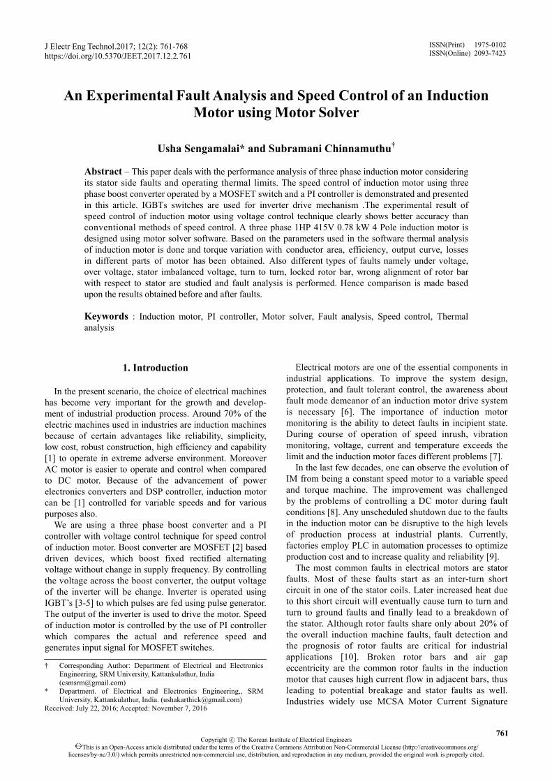
Method, reduction the stress on circuit can be achieved by controlling the voltage across only the MOSFET instead of changing the supply voltage directly. The block diagram of speed control shows a three phase ac supply given to the rectifier which converts ac to dc. Then it is given to a filter the output of Filter is given to boost converter which boosts the voltage from 170v to 400v.
The boosted voltage is given to an inverter which converts dc back to ac. Then the output is fed to a filter for reducing the ripples, which is then fed to an induction motor. The speed is taken as a feedback here which is given to the PI controller. An external reference signal is given to PI controller. Both the signals are compared using comparator and the error is given as feedback to MOSFET.
Fig. 1. Block diagram of speed control
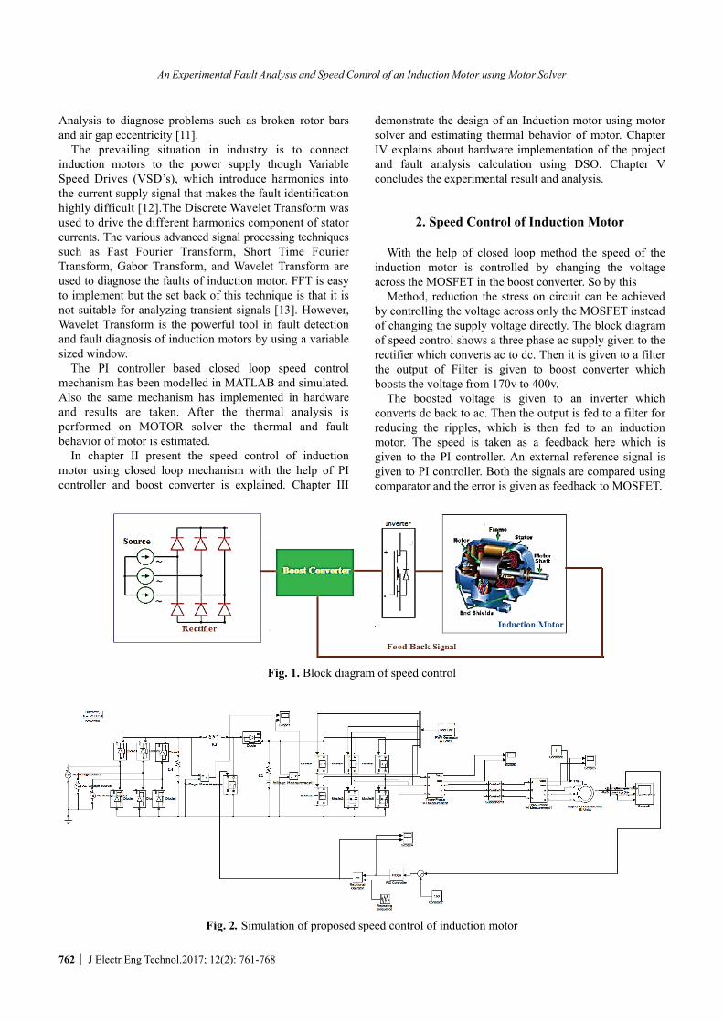
Fig. 2. Simulation of proposed speed control of induction motor
Usha Sengamalai and Subramani Chinnamuthu
http://www.jeet.or.kr │ 763
Controlling the speed of induction motor is to control the voltage across the boost converter. Three phase supply is given to the rectifier .After rectification the output is fed to boost the converter. Boost converter is used here to boost the input voltage from 170V to 400V.When the MOSFET switch is ON, inductor gets short circuited across the source and current in the inductor will increase enormously. When the MOSFET switch is OFF, current in the inductor gets boosted after addition of supply current.
The output which is obtained is fed to the filter to reduce the ripples and then fed to the inverter which converts dc to ac supply. The output of inverter is fed to a LC filter and eventually fed to the induction motor. The inverter used here is operated in 120 degree mode. The speed of induction motor is taken as feedback, along with constant reference speed and is given to the comparator. The
comparator compares the difference between both the signals and generates the error signal. The error signal is given to the PI controller. This controller generates a signal proportional to error signal which integrates the signal and the resultant is fed to the MOSFET switch to control the voltage across the MOSFET. This loop continues till error become zero and the speed reaches the rated value.
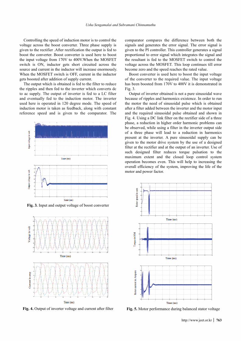
Boost converter is used here to boost the input voltage of the converter to the required value. The input voltage has been boosted from 170V to 400V it is demonstrated in Fig. 3.
Output of inverter obtained is not a pure sinusoidal wave because of ripples and harmonics existence. In order to run the motor the need of sinusoidal pulse which is obtained after a filter added between the inverter and the motor input and the required sinusoidal pulse obtained and shown in Fig. 4. Using a DC link filter on the rectifier side of a three phase, a reduction in higher order harmonic problems can be observed, while using a filter in the inverter output side of a three phase will lead to a reduction in harmonics present at the inverter. A pure sinusoidal supply can be given to the motor drive system by the use of a designed filter at the rectifier and at the output of an inverter. Use of such designed filter reduces torque pulsation to the maximum extent and the closed loop control system operation becomes even. This will help to increasing the overall efficiency of the system, improving the life of the motor and power factor.
Fig. 3. Input and output voltage of boost converter
Fig. 4. Output of inverter voltage and current after filter
Fig. 5. Motor performance during balanced stator voltage
An Experimental Fault Analysis and Speed Control of an Induction Motor using Motor Solver
764 │ J Electr Eng Technol.2017; 12(2): 761-768
The motor speed, torque and rotor current are projected in Fig. 5. During the transient analysis rotor speed after some pulsation attends the rated speed of 1500 rpm. Similarly the rotor current and electromagnetic torque has attained their steady state values after some deviation due
to inner disturbances. Since torque is directly proportional to current, waveform of both the curve will be almost the same.
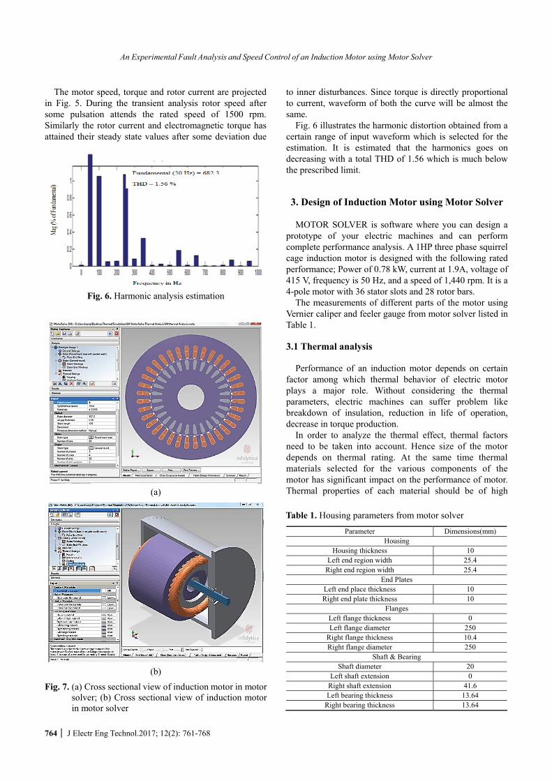
Fig. 6 illustrates the harmonic distortion obtained from a certain range of input waveform which is selected for the estimation. It is estimated that the harmonics goes on decreasing with a total THD of 1.56 which is much below the prescribed limit.
3. Design of Induction Motor using Motor Solver MOTOR SOLVER is software where you can design a
prototype of your electric machines and can perform complete performance analysis. A 1HP three phase squirrel cage induction motor is designed with the following rated performance; Power of 0.78 kW, current at 1.9A, voltage of 415 V, frequency is 50 Hz, and a speed of 1,440 rpm. It is a 4-pole motor with 36 stator slots and 28 rotor bars.
The measurements of different parts of the motor using Vernier caliper and feeler gauge from motor solver listed in Table 1.
3.1 Thermal analysis
Performance of an induction motor depends on certain
factor among which thermal behavior of electric motor plays a major role. Without considering the thermal parameters, electric machines can suffer problem like breakdown of insulation, reduction in life of operation, decrease in torque production.
In order to analyze the thermal effect, thermal factors need to be taken into account. Hence size of the motor depends on thermal rating. At the same time thermal materials selected for the various components of the motor has significant impact on the performance of motor. Thermal properties of each material should be of high
Fig. 6. Harmonic analysis estimation
(a)
(b)
Fig. 7. (a) Cross sectional view of induction motor in motor solver; (b) Cross sectional view of induction motorin motor solver
Table 1. Housing parameters from motor solver
Parameter Dimensions(mm) Housing
Housing thickness 10 Left end region width 25.4
Right end region width 25.4 End Plates
Left end place thickness 10 Right end plate thickness 10
Flanges Left flange thickness 0 Left flange diameter 250
Right flange thickness 10.4 Right flange diameter 250
Shaft & Bearing Shaft diameter 20
Left shaft extension 0 Right shaft extension 41.6 Left bearing thickness 13.64
Right bearing thickness 13.64
Usha Sengamalai and Subramani Chinnamuthu
http://www.jeet.or.kr │ 765
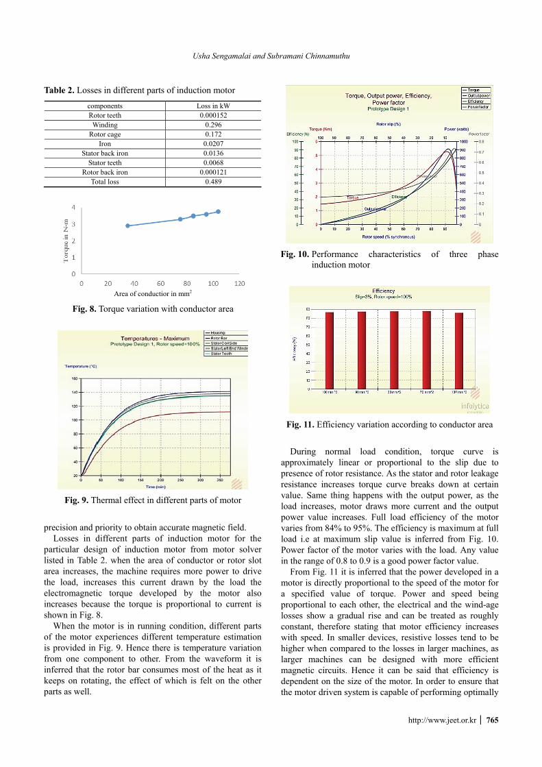
precision and priority to obtain accurate magnetic field. Losses in different parts of induction motor for the
particular design of induction motor from motor solver listed in Table 2. when the area of conductor or rotor slot area increases, the machine requires more power to drive the load, increases this current drawn by the load the electromagnetic torque developed by the motor also increases because the torque is proportional to current is shown in Fig. 8.
When the motor is in running condition, different parts of the motor experiences different temperature estimation is provided in Fig. 9. Hence there is temperature variation from one component to other. From the waveform it is inferred that the rotor bar consumes most of the heat as it keeps on rotating, the effect of which is felt on the other parts as well.
During normal load condition, torque curve is approximately linear or proportional to the slip due to presence of rotor resistance. As the stator and rotor leakage resistance increases torque curve breaks down at certain value. Same thing happens with the output power, as the load increases, motor draws more current and the output power value increases. Full load efficiency of the motor varies from 84% to 95%. The efficiency is maximum at full load i.e at maximum slip value is inferred from Fig. 10. Power factor of the motor varies with the load. Any value in the range of 0.8 to 0.9 is a good power factor value.
From Fig. 11 it is inferred that the power developed in a motor is directly proportional to the speed of the motor for a specified value of torque. Power and speed being proportional to each other, the electrical and the wind-age losses show a gradual rise and can be treated as roughly constant, therefore stating that motor efficiency increases with speed. In smaller devices, resistive losses tend to be higher when compared to the losses in larger machines, as larger machines can be designed with more efficient magnetic circuits. Hence it can be said that efficiency is dependent on the size of the motor. In order to ensure that the motor driven system is capable of performing optimally
Table 2. Losses in different parts of induction motor
components Loss in kW Rotor teeth 0.000152
Winding 0.296 Rotor cage 0.172
Iron 0.0207 Stator back iron 0.0136
Stator teeth 0.0068 Rotor back iron 0.000121
Total loss 0.489
Area of conductior in mm2
Fig. 8. Torque variation with conductor area
Fig. 9. Thermal effect in different parts of motor
Fig. 10. Performance characteristics of three phase induction motor
Fig. 11. Efficiency variation according to conductor area
An Experimental Fault Analysis and Speed Control of an Induction Motor using Motor Solver
766 │ J Electr Eng Technol.2017; 12(2): 761-768
over time, selection of right equipment, efficient motors, drives and achieving motor system optimization needs to be carefully taken into account. A proper motor management plan must also be developed for the overall motor system. If the conductor area increases, it would imply that efficiency should decease. Thus efficiency of the system depends upon the conductor area. Taking care of the fact that the desired performance parameter stays within the desired levels, efficiency is plotted as a function of conductor.
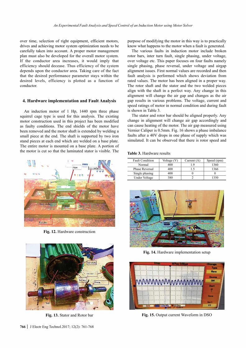
4. Hardware implementation and Fault Analysis An induction motor of 1 Hp, 1440 rpm three phase
squirrel cage type is used for this analysis. The existing motor construction used in this project has been modified as faulty conditions. The end shields of the motor have been removed and the motor shaft is extended by welding a small piece at the end. The shaft is supported by two iron stand pieces at each end which are welded on a base plate. The entire motor is mounted on a base plate. A portion of the motor is cut so that the laminated stator is visible. The
purpose of modifying the motor in this way is to practically know what happens to the motor when a fault is generated.
The various faults in induction motor include broken rotor bars, inter turn fault, single phasing, under voltage, over voltage etc. This paper focuses on four faults namely single phasing, phase reversal, under voltage and airgap alignment issues. First normal values are recorded and then fault analysis is performed which shows deviation from rated values. The motor has been aligned in a proper way. The rotor shaft and the stator and the two welded pieces align with the shaft in a perfect way. Any change in this alignment will change the air gap and changes as the air gap results in various problems. The voltage, current and speed ratings of motor in normal condition and during fault is shown in Table 3.
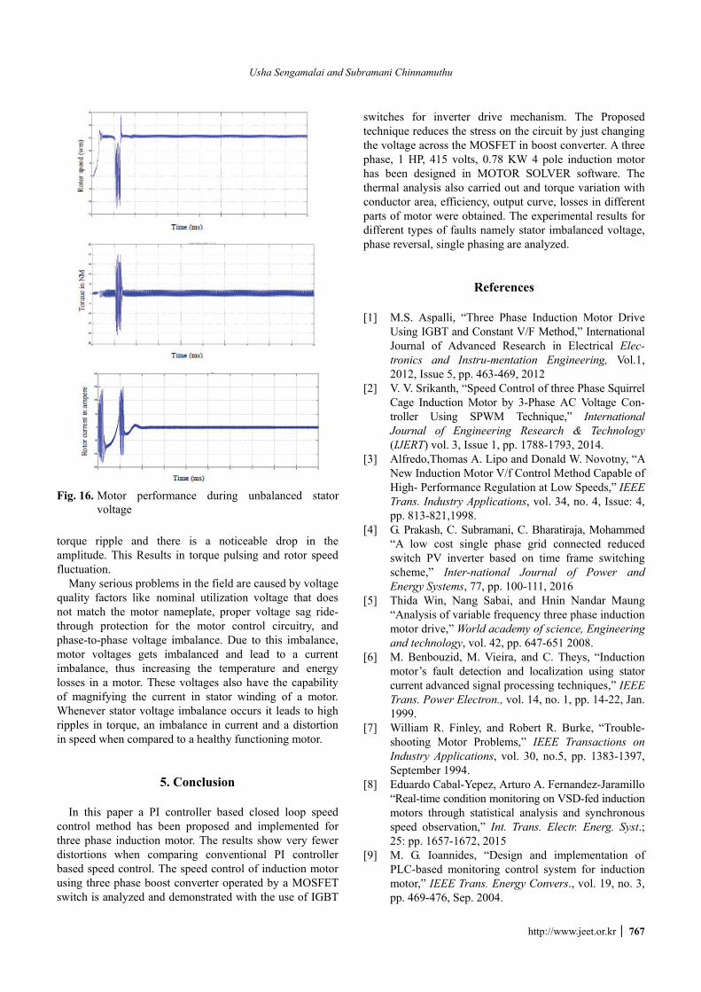
The stator and rotor bar should be aligned properly. Any change in alignment will change air gap accordingly and can cause heating of the motor. The air gap measured using Vernier Caliper is 0.5mm. Fig. 16 shows a phase imbalance faults after a 40V drops in one phase of supply which was simulated. It can be observed that there is rotor speed and
Fig. 12. Hardware construction
Fig. 13. Stator and Rotor bar
Table 3. Hardware results
Fault Condition Voltage (V) Current (A) Speed (rpm)Normal 400 1.9 1360
Phase Reversal 400 1.5 1366 Single phasing 400 0 0 Under Voltage 380 2 1350
Fig. 14. Hardware implementation setup
Fig. 15. Output current Waveform in DSO
Usha Sengamalai and Subramani Chinnamuthu
http://www.jeet.or.kr │ 767
torque ripple and there is a noticeable drop in the amplitude. This Results in torque pulsing and rotor speed fluctuation.
Many serious problems in the field are caused by voltage quality factors like nominal utilization voltage that does not match the motor nameplate, proper voltage sag ride-through protection for the motor control circuitry, and phase-to-phase voltage imbalance. Due to this imbalance, motor voltages gets imbalanced and lead to a current imbalance, thus increasing the temperature and energy losses in a motor. These voltages also have the capability of magnifying the current in stator winding of a motor. Whenever stator voltage imbalance occurs it leads to high ripples in torque, an imbalance in current and a distortion in speed when compared to a healthy functioning motor.
5. Conclusion In this paper a PI controller based closed loop speed
control method has been proposed and implemented for three phase induction motor. The results show very fewer distortions when comparing conventional PI controller based speed control. The speed control of induction motor using three phase boost converter operated by a MOSFET switch is analyzed and demonstrated with the use of IGBT
switches for inverter drive mechanism. The Proposed technique reduces the stress on the circuit by just changing the voltage across the MOSFET in boost converter. A three phase, 1 HP, 415 volts, 0.78 KW 4 pole induction motor has been designed in MOTOR SOLVER software. The thermal analysis also carried out and torque variation with conductor area, efficiency, output curve, losses in different parts of motor were obtained. The experimental results for different types of faults namely stator imbalanced voltage, phase reversal, single phasing are analyzed.
References
[1] M.S. Aspalli, “Three Phase Induction Motor Drive Using IGBT and Constant V/F Method,” International Journal of Advanced Research in Electrical Elec-tronics and Instru-mentation Engineering, Vol.1, 2012, Issue 5, pp. 463-469, 2012
[2] V. V. Srikanth, “Speed Control of three Phase Squirrel Cage Induction Motor by 3-Phase AC Voltage Con-troller Using SPWM Technique,” International Journal of Engineering Research & Technology (IJERT) vol. 3, Issue 1, pp. 1788-1793, 2014.
[3] Alfredo,Thomas A. Lipo and Donald W. Novotny, “A New Induction Motor V/f Control Method Capable of High- Performance Regulation at Low Speeds,” IEEE Trans. Industry Applications, vol. 34, no. 4, Issue: 4, pp. 813-821,1998.
[4] G. Prakash, C. Subramani, C. Bharatiraja, Mohammed “A low cost single phase grid connected reduced switch PV inverter based on time frame switching scheme,” Inter-national Journal of Power and Energy Systems, 77, pp. 100-111, 2016
[5] Thida Win, Nang Sabai, and Hnin Nandar Maung “Analysis of variable frequency three phase induction motor drive,” World academy of science, Engineering and technology, vol. 42, pp. 647-651 2008.
[6] M. Benbouzid, M. Vieira, and C. Theys, “Induction motor’s fault detection and localization using stator current advanced signal processing techniques,” IEEE Trans. Power Electron., vol. 14, no. 1, pp. 14-22, Jan. 1999.
[7] William R. Finley, and Robert R. Burke, “Trouble-shooting Motor Problems,” IEEE Transactions on Industry Applications, vol. 30, no.5, pp. 1383-1397, September 1994.
[8] Eduardo Cabal-Yepez, Arturo A. Fernandez-Jaramillo “Real-time condition monitoring on VSD-fed induction motors through statistical analysis and synchronous speed observation,” Int. Trans. Electr. Energ. Syst.; 25: pp. 1657-1672, 2015
[9] M. G. Ioannides, “Design and implementation of PLC-based monitoring control system for induction motor,” IEEE Trans. Energy Convers., vol. 19, no. 3, pp. 469-476, Sep. 2004.
Fig. 16. Motor performance during unbalanced stator
voltage
An Experimental Fault Analysis and Speed Control of an Induction Motor using Motor Solver
768 │ J Electr Eng Technol.2017; 12(2): 761-768
[10] W. T. Thomson, M. Fenger, “Current signature analysis to detect induction motor faults,” IEEE Industry Applications Magazine, vol. 7, pp. 26-34, July/Aug. 2001.
[11] William. T. Thomson and Mark fenger, “Current signature analysis to detect induction motor faults,” IEEE Transaction. On IAS Magazine, vol. 7, no. 4, pp. 26-34, July / August 2001.
[12] Eduardo Cabal-Yepez, Arturo A. Fernandez-Jaramillo, Arturo Garcia-Perez, Rene J. Romero-Troncoso and Jose M. Lozano-Garcia. “Real-time condition moni-toring on VSD-fed induction motors through statistical analysis and synchronous speed observation,” Inter-national Transactions on Electrical Energy Systems, 25, pp. 1657-1672, 2015
[13] A.C. Megherbi, H. Megherbi “Parameter Identifi-cation of Induction Motors using Variable-weighted Cost Function of Genetic Algorithms’ Journal of Electrical Engineering & Technology, vol. 5, no. 4, pp. 597~605, 2010
Usha Sengamalai, she received B.E Electrical and Electronics Engineering and M.E Power Electronics and Drives from Anna University, Chennai in 2007 and 2012 respectively. She is currently pursuing Ph.D in SRM University, Also working as an Assistant professor in the department of Electrical and
Electronics Engineering SRM University. Her area of interest is Power Electronics Converters and Stability analysis of Induction motors.
Subramani Chinnamuthu, he received B.E Electrical and Electronics Engin-eering from Bharathiar University and M.E Power Systems from Anna University, Chennai in 2004 and 2006 respectively. He has completed Ph.D degree in Electrical and Electronics Engineering from SRM University in
2012. He is presently working as an Assistant professor in the Department of Electrical and Electronics Engineering SRM University. He has published 52 research papers in referred International Journals/Conferences. He is having 15 years of teaching and industrial experience. His research areas are power system stability, power system control and FACTS, electrical machine design.