NATIONAL ",'Ci ,L ESIABI..ISI-lMEN'I LIBRARY R. & M. No. 2626 (HI,509) A.RC. Technical Report An Experimental Investigation on the Flutter Characteristics of a Model Flying Wing By N. C. LAMBOURNE, B.Sc., of the Aerodynamics Division, N.P.L. CVGWn Copyright ReslWVod LONDON : HER MAJESTY'S STATIONERY OFFICE 1952 PRICE 6s 6d NET
Transcript
NATIONAL A£RO~i;\: ",'Ci ,L ESIABI..ISI-lMEN'I
LIBRARYR. & M. No. 2626
(HI,509)A.RC. Technical Report
An Experimental Investigation on the FlutterCharacteristics of a Model Flying Wing
By
N. C. LAMBOURNE, B.Sc.,of the Aerodynamics Division, N.P.L.
liBRARYAn Experimental Investigation on the Flutter
Characteristics of a Model Flying Wing
Byjl
N. c. -LAMBOURNE, B.Sc., of the Aerodynamics Division, N.P.L. l r
li.vaIiJ\l. ( .~ -. --- ,ml
/ L t~~~\ 1.~,5~ \ •... "'. _..."
Summary.-This report describes some preliminary experimental work that has been carried out in an attemptto gain information on the flexural-torsional flutter characteristics of flying wing types of aircraft. Tests were madewith two flexible tip-to-tip models:-
A Rectangular plan form.B Cranked and tapered plan form.
The method of supporting the models in the wind tunnel allowed certain bodily freedoms to be present either singlyor simultaneously, and measurements were made of critical speeds and frequencies, and in a few cases the flutter motionwas analysed by means of cinematograph records. The experimental results are in no way conclusive and cannotbe directly applied to full-scale problems, but they do point to some of the difficulties in the treatment of the flutterof flying wings. Further, the difficulties encountered during the flutter tests themselves lead to suggestedmodifications in the technique of providing a model in a wind tunnel with the bodily freedoms appropriate to freeflight conditions.
1. General Lntroduction.e-Yx: the problem of wing flutter of conventional single-engined aeroplanes it is usually assumed that the critical speed that will be met in practice is only slightlydifferent from that which would be obtained were the fuselage immobile. Frazer and Duncan'(1931) investigated theoretically the effect of fuselage mobility on binary flexural-aileron flutterfor one particular aeroplane that was typical of practice at that time. Their conclusions werethat the critical speed for longitudinal-symmetrical flutter differs little from that which isobtained when the fuselage is regarded as immobile, and that the critical speed for lateral-antisymmetrical flutter is considerably higher than that corresponding to a fixed fuselage. Thesame authors also give one calculation to show that freedom of the fuselage in roll raises the criticalspeed for anti-symmetrical flutter of the ternary flexural-torsional-aileron type. More recentlyW. P. jones" (1944) has examined the case of anti-symmetrical flutter of a large transport aeroplane when the ailerons are mass underbalanced. He treats, inter alia, the cases of binaryflexural-aileron flutter and of ternary flexural-torsional-aileron flutter, and concludes that thecritical speeds for both types are raised by the introduction of rolling mobility.
As far as pure flexural-torsional flutter is concerned the effect of fuselage mobility in roll hasbeen investigated theoretically by Pugsley, Morris and Naylor" (1939). They conclude that fora single-engined aeroplane anti-symmetrical flutter is the least probable in practice, and theypoint out that in symmetrical flutter the vertical motion of the fuselage is likely to be smallsince the associated mass is large compared with the wings. Similarly, since the pitching momentof inertia of the fuselage is large compared with that of the wings, it may also be concludedthat the pitching motion of the fuselage will be small during symmetrical flexural-torsionalflutter.
Published with the permission of the Director, National Physical Laboratory.
1
Although most of the foregoing evidence refers to flutter involving aileron movements, it hasbeen usual to regard the effect of fuselage mobility on the flexural-torsional flutter speed asnegligible, at least with single-engined aeroplanes. Valuable experimental investigations withhalf-span model wings rigidly held at their roots have been carried out on this basis. Not onlywere the experiments able to provide controls on critical speed calculations, but the resultscould, with a considerable measure of truth, be directly applied on a basis of dynamical similarityto the flutter of actual aircraft.
In the case of an aeroplane with wing engines, where up to roughly three-quarters of the totalweight may be located in the wings, the mobility of the fuselage becomes important. Experimentation using model cantilever wings rigidly attached at the root is still able to providecontrols on calculations, but the results of the experiments are no longer directly applicable tothe flutter which might occur in flight. With the advent of the flying wing type of aircraft inwhich there is a relatively uniform distribution of mass over a single lifting surface a moregeneral approach to the flutter problem must be sought. The instabilities which may occur inflight can no longer be conveniently separated into those that do not involve structural distortions(i.e., the bodily oscillations dealt with by classical aircraft stability theory) and those that onlyinvolve structural distortions and control surface movements (i.e., flutter).
The flutter problem of practical flying wings is also complicated by the sweep back (or forward)which will be present for the purposes of attaining both 'rigid body' stability and high speeds.
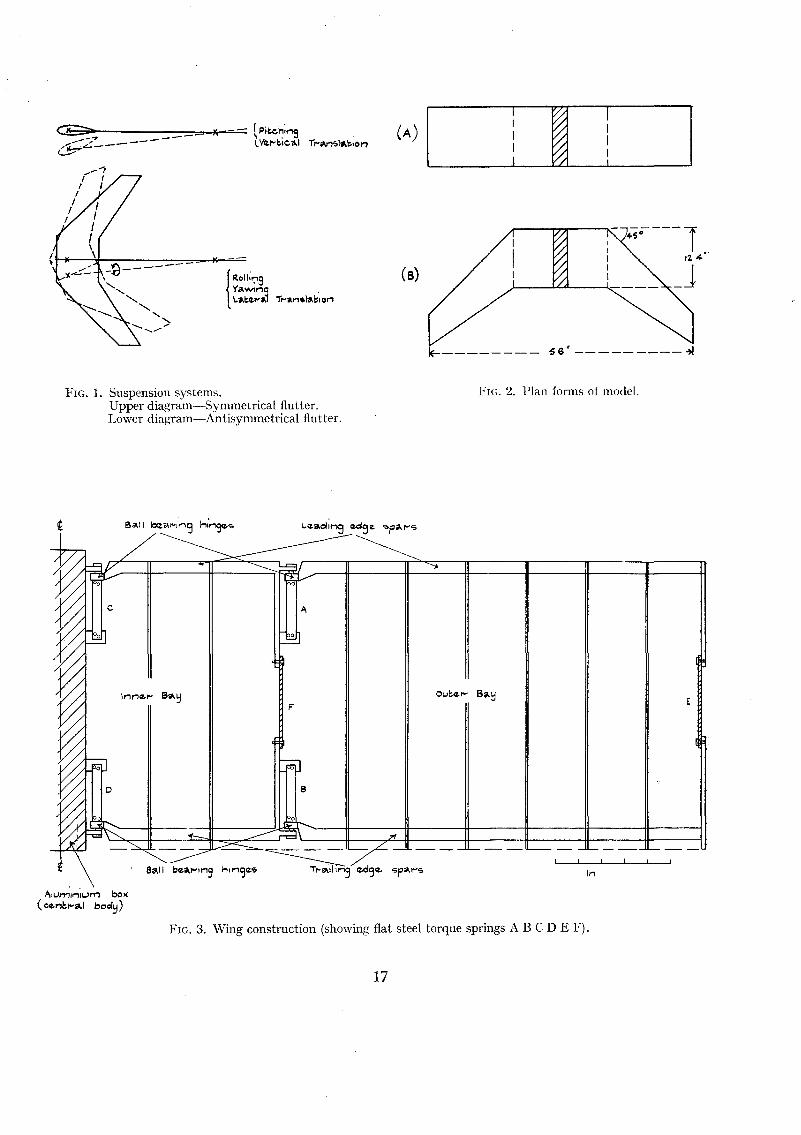
The investigation to be described was concerned mainly with the problem of mounting a modelflying wing in a wind tunnel so as to provide satisfactory allowances for true bodily freedomswhich are present in flight. In the main the system of supporting the model was designed onthe lines suggested by Frazer;' the models themselves consisted of flexible wings attached to acentral body which could be supported in either of two manners for separate study of the symmetrical and the anti-symmetrical types of oscillations. The two interchangeable suspensionsystems provided the following alternative sets of bodily freedoms (see Fig. 1):-
(i) Appropriate to symmetrical flutter.
Pitching.
Vertical translation.
(ii) Appropriate to anti-symmetrical flutter.
Rolling.
Yawing.
Lateral translation.
Tests were carried out with two tip-to-tip models* (see Fig. 2) as follows:
(A) Rectangular.
(B) Tapered and cranked.
The experiments with A were intended primarily as a simple approach to the more generalproblem. .
'" Tests with a further model (tapered without sweep back) were originally intended, but on the completion of thework with the other two models it was not considered worthwhile to proceed with the construction of the third,
The original experimental programme was ambitious in including provision for the variationof the stiffness and mass loading of the wings. In practice, however, the adjustments necessaryto match the stiffnesses of the port and starboard wings were so tedious that no attempt was madeto vary the wing stiffnesses once these matching adjustments were complete; nor was any attemptmade to vary the wing inertias, and the flutter tests all relate to the effect of the freedoms of thecentral body.
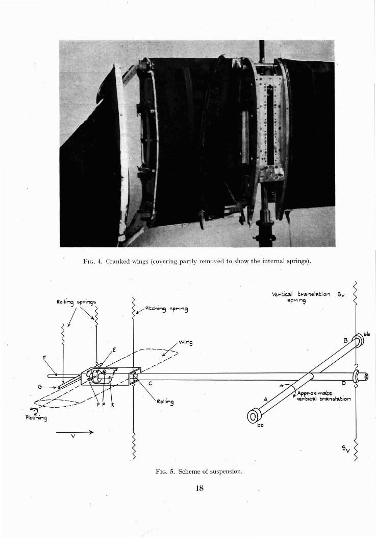
2. Description of Model Wings.-The plan forms of the models are shown in Fig. 2. Eachwing (root to tip) consisted of two separate parts, an inner and an outer bay, the inner baybeing common to both the rectangular and the cranked model. The internal wing structurewas designed to provide easily definable stiffness properties, and was of course not representativeof actual practice. The general layout of the rectangular wings is shown in Fig. 3, whilst theouter bays of the cranked wings were constructed on similar lines except that the spars wereswept back. Wooden spars at the leading and trailing edges of the inner bay were independentlyhinged by means of small ball bearings to an aluminium box (the central body) which is describedin section 3. The spars were also connected to the central body by flat steel strips, C and D,which acted as torsion springs and constrained the hinging of the spars. The leading and trailingedge spars of the outer bay were similarly hinged to the outer ribs of the inner bay and wereconstrained by the steel strips A and B. The spars themselves were T-sectioned, quite stiff inbending but flexible in torsion, so that, whilst the flexure of the wing was controlled directlyby the 4 springs A, B, C and D, wing torsion took place by the differential hinging of the leadingedge spars. Thus, the torsional stiffness of the wing was dependent not only on the 4 springs butalso on the characteristics of the wooden structure itself. Provision was also made for crossconnection of the leading and trailing edges by flat steel strips E and F at the outer sections ofboth bays, so that the torsional stiffness of the wing could be adjusted independently of theflexural stiffness. The leading and trailing-edge spars were also cross-connected at a number ofpoints by light wooden ribs parallel to the longitudinal axis of the complete model and definingthe aerodynamic sections. The inner and outer bays were separately covered with vaselinedoped silk and access to the springs was gained by removal of portions of the coverings (seeFig. 4).
3. Description of Support System.-The two interchangeable support systems shown in Fig. 1have been described in outline in section 1. The apparatus as arranged for the case of symmetricalflutter and with all the possible spring attachments is shown diagramatically in Fig. 5. Rod ABwas mounted in ball bearings bb attached to the walls of the wind tunnel. Rod CD, which wasintegral with AB, was arranged along the wind axis and supported by springs S", A lightaluminium box which formed the central body to which the wings were attached, could pitch
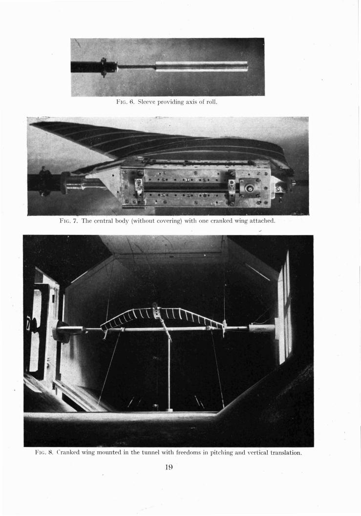
. about an axis through the ball bearings P,P; these small bearings were carried by a fitting Eclamped to a sleeve R at the upstream end of rod CD, (see also Fig. 6). This sleeve was itselfmounted on small ball bearings and could turn about its own axis to provide a rolling freedom forthe model. During tests involving symmetrical flutter this last degree of freedom was of courselocked. The wing-body combination then had two possible bodily freedoms as follows:-
1 Pitching about PP.
2 Pitching about AB (approximately a freedom in vertical translation and subsequentlyreferred to as such).
Independent clamps were provided so that either or both of these freedoms could be eliminated,and the majority of the tests described in this report refer to pitching freedom about PP only.In this case the central body was supported in the horizontal position by the pitching springsas shown in the diagram. It may be noted that if both the freedoms had been present simultaneously a cross stiffness would have been introduced by the pitching springs.
3
It was possible to fix the pitching axis at various positions behind the leading edge of the modeland the pitching inertia could be varied by masses clamped to rod F. Fig. 7 shows the aluminiumbox with one wing attached. During the flutter tests the box was shielded by a plywood cover,and Fig. 8 shows the complete apparatus mounted in the wind tunnel.
For the case of anti-symmetrical flutter it was intended to keep the plane of the wings hori-zontal with the supporting apparatus reorientated as follows:-
1 Axis PP vertical, to form the axis of yawing.
2 Axis AB vertical, to provide approximately lateral translation.
3 Rolling freedom unlocked.
The experimental difficulties encountered during the tests with freedoms appropriate to symmetrical flutter led to the conclusion that the alternative arrangement of the apparatus wouldnot be satisfactory for tests involving anti-symmetrical flutter. In fact, rolling was the onlyfreedom appropriate to anti-symmetrical flutter that was used.
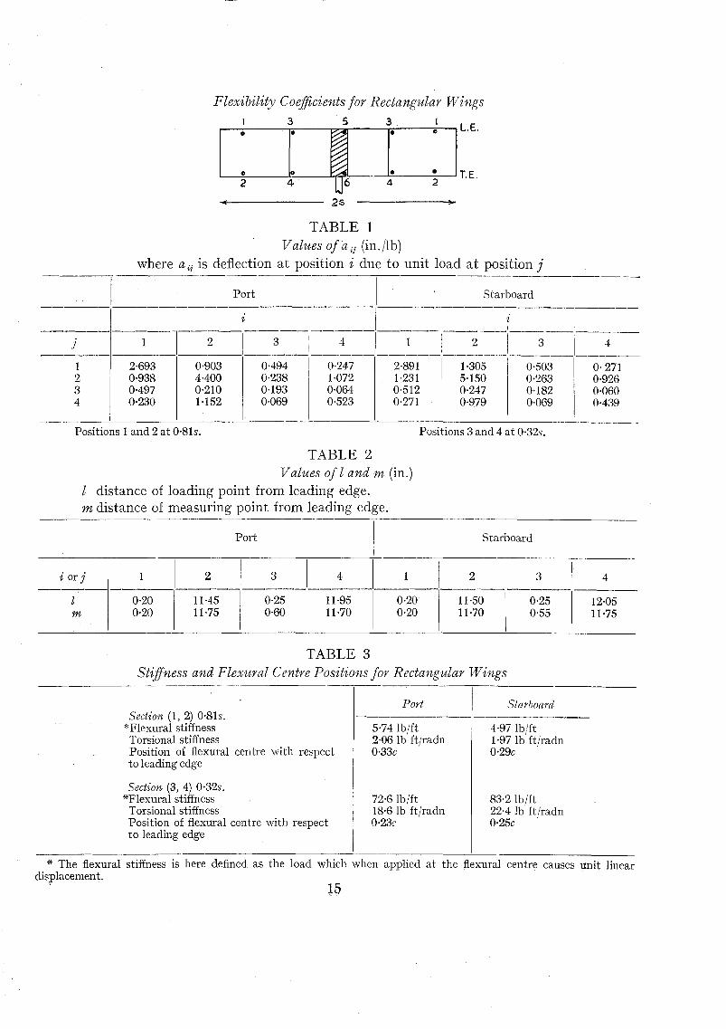
4. Experiments with Rectangular Wings.--Elastic Stiffness and Flexibility ColJ.7fcients.-Theelastic properties were determined by means of flexibility coefficients referring to points 1, 2,3, 4on each wing (see Table 1).
From these measurements the flexural and torsional stiffnesses and the positions of the flexuralcentres were obtained on the assumption that the chordwise sections do not distort. The loadswere applied to the spars themselves, and the vertical displacements of needles attached to thespars near the loading points were measured by means of micrometer heads. During thesemeasurements the central body was clamped as effectively as possible and equal loads were appliedat corresponding positions in both the port and starboard wings, so that any deflection due tothe slight residual flexibility in roll was eliminated. There was, however, some movement ofthe central body in the vertical plane, and displacements were also measured at two additionalpoints 5, 6, so that corrections could be applied to the wing deflections. It was found that creepoccurred after a load had been applied, and to obtain consistent sets of coefficients the wingswere allowed to settle for 4 minutes before readings were taken.
Although the port and starboard wings were constructed in the same manner and similarflat steel springs were fitted in each, it was found at the outset that the two wings had vastlydifferent stiffnesses. Much time was spent in altering the stiffnesses of the steel springs bymodifying either their width or thicknesses until the wings had approximately equal stiffnesses.
The method of carrying out these adjustments was firstly to remove the outer bays, andmodify springs C and D (see Fig. 3) by trial and error until the flexural stiffnesses and positionsof the flexural centre at sections (3, 4) were approximately the same for both wings. It was thenfound that the torsional stiffnesses of the inner bays were also in reasonable agreement, and noalteration of spring F was necessary. The outer bays were then attached and springs A and Bwere modified until the flexural stiffnesses and positions of the flexural centres as measured atsections (1, 2) were the same for both wings. It was again found that the torsional stiffnessesmeasured at these sections were in agreement, and no alteration of spring E was necessary.
The final elastic properties of the two wings are contained in Table 1, where aij is the deflectionat position i due to unit load at position i The measuring and loading positions did not quitecoincide and they are given in Table 2.
A more convenient picture of the final elastic state of the wings is provided by Table 3 whichgives the flexural and torsion stiffnesses and the positions of the flexural centre for sections (1, 2)and (3, 4).
4
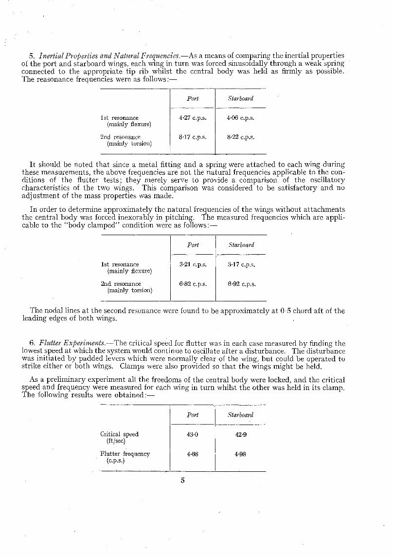
5. Inertial Properties and Natural Frequencies.-As a means of comparing the inertial propertiesof the port and starboard wings, each wing in turn was forced sinusoidally through a weak springconnected to the appropriate tip rib whilst the central body was held as firmly as possible.The reasonance frequencies were as follows:-
]Dort Starboard
1st resonance(mainly flexure)
2nd resonance(mainly torsion)
4·27 c.p.s.
8·17 c.p.s,
4·06 c.p.s.
8·22 c.p.s,
It should be noted that since a metal fitting and a spring were attached to each wing duringthese measurements, the above frequencies are not the natural frequencies applicable to the conditions of the flutter tests; they merely serve to provide a comparison of the oscillatorycharacteristics of the two wings. This comparison was considered to be satisfactory and noadjustment of the mass properties was made.
In order to determine approximately the natural frequencies of the wings without attachmentsthe central body was forced inexorably in pitching. The measured frequencies which are applicable to the "body clamped" condition were as follows:-
]Dort Starboard
1st resonance(mainly flexure)
2nd resonance(mainly torsion)
3·21 c.p.s,
6·82 c.p.s.
3·17 c.p.s.
6·92 c.p.s,
The nodal lines at the second resonance were found to be approximately at 0·5 chord aft of theleading edges of both wings. ,
6. Flutter Experiments.-The critical speed for flutter was in each case measured by finding thelowest speed at which the system would continue to oscillate after a disturbance. The disturbancewas initiated by padded levers which were normally clear of the wing, but could be operated tostrike either or both wings. Clamps were also provided so that the wings might be held.
As a preliminary experiment all the freedoms of the central body were locked, and the criticalspeed and frequency were measured for each wing in turn whilst the other was held in its clamp.The following results were obtained:-
]Dort Starboard
Critical speed 43·0 42·9(it/sec)
Flutter frequency 4·68 4·98(c.p.s.)
5
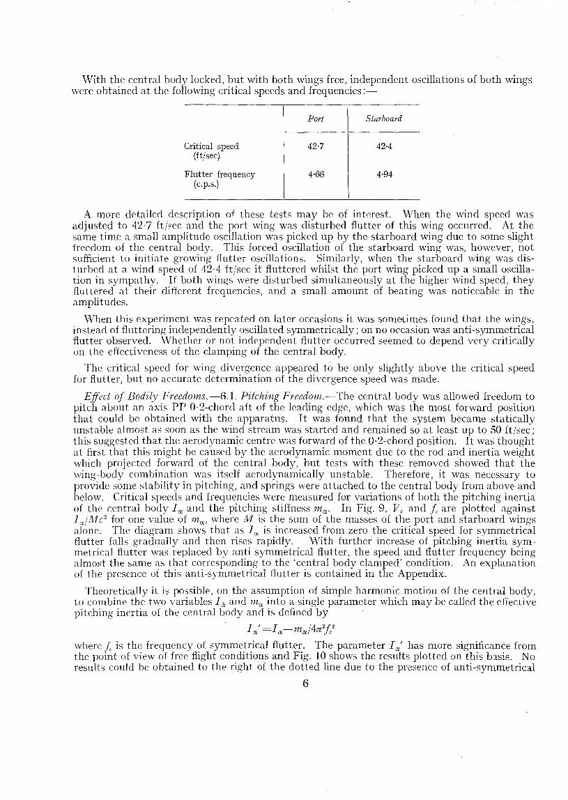
With the central body locked, but with both wings free, independent oscillations of both wingswere obtained at the following critical speeds and frequencies:-
Port Starboard
Critical speed 42·7 42·4(ft/sec)
Flutter frequency 4·66 4·94(c.p.s.)
A more detailed description of these tests may be of interest. When the wind speed wasadjusted to 42·7 ft/:::ec and the port wing was disturbed flutter of this wing occurred. At thesame time a small amplitude oscillation was picked up by the starboard wing due to some slightfreedom of the central body. This forced oscillation of the starboard wing was, however, notsufficient to initiate growing flutter oscillations. Similarly, when the starboard wing was disturbed at a wind speed of 42-4 it/sec it fluttered whilst the port wing picked up a small oscillation in sympathy. If both wings were disturbed simultaneously at the higher wind speed, theyfluttered at their different frequencies, and a small amount of beating was noticeable in theamplitudes.
When this experiment was repeated on later occasions it was sometimes found that the wings,instead of fluttering independently oscillated symmetrically; on no occasion was anti-symmetricalflutter observed. Whether or not independent flutter occurred seemed to depend very criticallyon the effectiveness of the clamping of the central body.
The critical speed for wing divergence appeared to be only slightly above the critical speedfor flutter, but no accurate determination of the divergence speed was made.
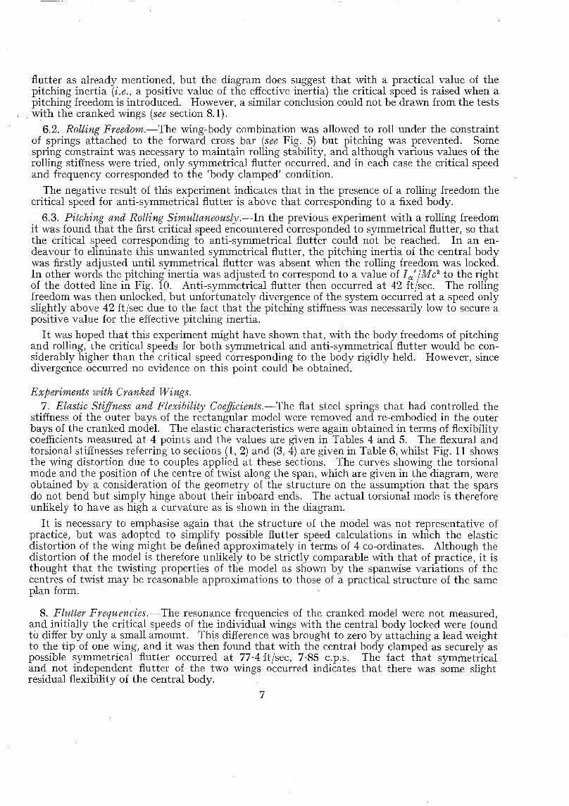
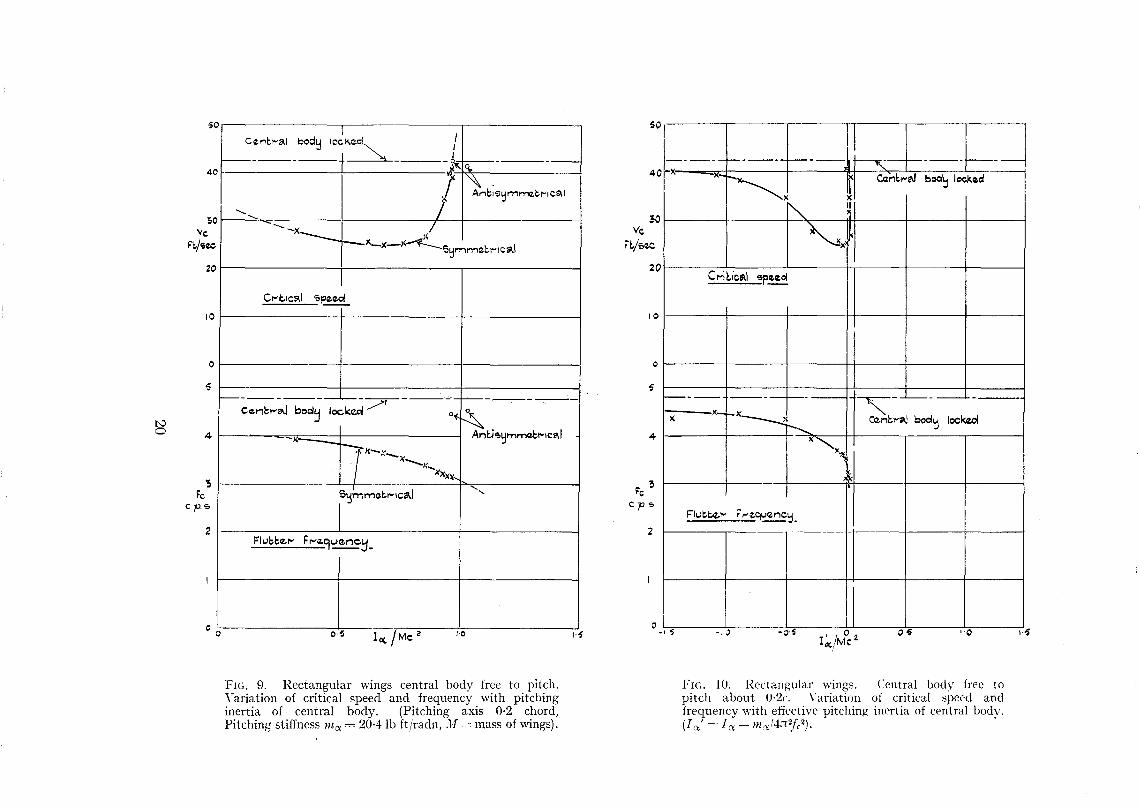
Effect of Bodily Freedoms.-6.1. Pitching Freedom.-The central body was allowed freedom topitch about an axis PP 0·2-chord aft of the leading edge, which was the most forward positionthat could be obtained with the apparatus. It was found that the system became staticallyunstable almost as soon as the wind stream was started and remained so at least up to 50 ft/sec;this suggested that the aerodynamic centre was forward of the 0·2-chord position. It was thoughtat first that this might be caused by the aerodynamic moment due to the rod and inertia weightwhich projected forward of the central body, but tests with these removed showed that thewing-body combination was itself aerodynamically unstable. Therefore, it was necessary toprovide some stability in pitching, and springs were attached to the central body from above andbelow. Critical speeds and frequencies were measured for variations of both the pitching inertiaof the central body 1 <X and the pitching stiffness m<X. In Fig. 9, Vc and I. are plotted against1<x/Mc2 for one value of m<x, where M is the sum of the masses of the port and starboard wingsalone. The diagram shows that as 1<X is increased from zero the critical speed for symmetricalflutter falls gradually and then rises rapidly. With further increase of pitching inertia symmetrical flutter was replaced by anti-symmetrical flutter, the speed and flutter frequency beingalmost the same as that corresponding to the 'central body clamped' condition. An explanationof the presence of this anti-symmetrical flutter is contained in the Appendix.
Theoretically it is possible, on the assumption of simple harmonic motion of the central body,to combine the two variables 1 ex and In<X into a single parameter which may be called the effectivepitching inertia of the central body and is defined by
1<x' =1<x-m<x/4n 2fc2
where f is the frequency of symmetrical flutter. The parameter 1 <x' has more significance fromthe point of view of free flight conditions and Fig. 10 shows the results plotted on this basis. Noresults could be obtained to the right of the dotted line due to the presence of anti-symmetrical
6
flutter as already mentioned, but the diagram does suggest that with a practical value of thepitching inertia (i.e., a positive value of the effective inertia) the critical speed is raised when apitching freedom is introduced. However, a similar conclusion could not be drawn from the tests
. with the cranked wings (see section 8.1).
6.2. Rolling Freedom.-The wing-body combination was allowed to roll under the constraintof springs attached to the forward cross bar (see Fig. 5) but pitching was prevented. Somespring constraint was necessary to maintain rolling stability, and although various values of therolling stiffness were tried, only symmetrical flutter occurred, and in each case the critical speedand frequency corresponded to the 'body clamped' condition.
The negative result of this experiment indicates that in the presence of a rolling freedom thecritical speed for anti-symmetrical flutter is above that corresponding to a fixed body.
6.3. Pitching and Rolling Simultaneously.-In the previous experiment with a rolling freedomit was found that the first critical speed encountered corresponded to symmetrical flutter, so thatthe critical speed corresponding to anti-symmetrical flutter could not be reached. In an endeavour to eliminate this unwanted symmetrical flutter, the pitching inertia of the central bodywas firstly adjusted until symmetrical flutter was absent when the rolling freedom was locked.In other words the pitching inertia was adjusted to correspond to a value of I ex'/Mc
2 to the rightof the dotted line in Fig. 10. Anti-symmetrical flutter then occurred at 42 £t/sec. The rollingfreedom was then unlocked, but unfortunately divergence of the system occurred at a speed onlyslightly above 42 ft/sec due to the fact that the pitching stiffness was necessarily low to secure apositive value for the effective pitching inertia.
It was hoped that this experiment might have shown that, with the body freedoms of pitchingand rolling, the critical speeds for both symmetrical and anti-symmetrical flutter would be considerably higher than the critical speed corresponding to the body rigidly held. However, sincedivergence occurred no evidence on this point could be obtained.
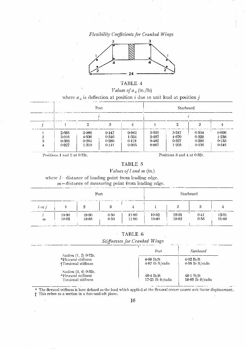
Experiments with Cranked Wings.7. Elastic Stiffness and Flexibility Coefficients.--The flat steel springs that had controlled the
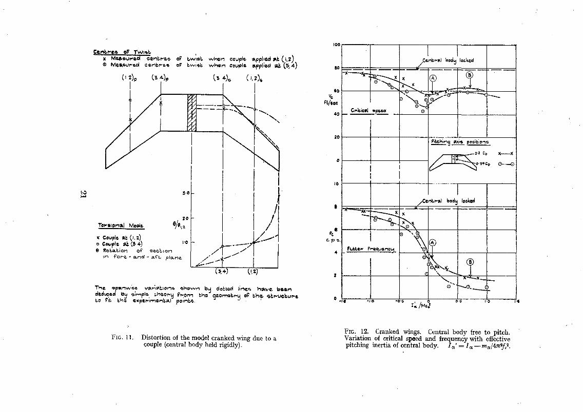
stiffness of the outer bays of the rectangular model were removed and re-embodied in the outerbays of the cranked model. The elastic characteristics were again obtained in terms of flexibilitycoefficients measured at 4 points and the values are given in Tables 4 and 5. The flexural andtorsional stiffnesses referring to sections (1, 2) and (3, 4) are given in Table 6, whilst Fig. 11 showsthe wing distortion due to couples applied at these sections. The curves showing the torsionalmode and the position of the centre of twist along the span, which are given in the diagram, wereobtained by a consideration of the geometry of the structure on the assumption that the sparsdo not bend but simply hinge about their inboard ends. The actual torsional mode is thereforeunlikely to have as high a curvature as is shown in the diagram.
It is necessary to emphasise again that the structure of the model was not representative ofpractice, but was adopted to simplify possible flutter speed calculations in which the elasticdistortion of the wing might be defined approximately in terms of 4 co-ordinates. Although thedistortion of the model is therefore unlikely to be strictly comparable with that of practice, it isthought that the twisting properties of the model as shown by the spanwise variations of thecentres of twist may be reasonable approximations to those of a practical structure of the sameplan form.
8. Flutter Frequencies.-The resonance frequencies of the cranked model were not measured,and initially the critical speeds of the individual wings with the central body locked were foundto differ by only a small amount. This difference was brought to zero by attaching a lead weightto the tip of one wing, and it was then found that with the central body clamped as securely aspossible symmetrical flutter occurred at 77·4 £t/sec, 7·85 c.p.s. The fact that symmetricaland not independent flutter of the two wings occurred indicates that there was some slightresidual flexibility of the central body.
7
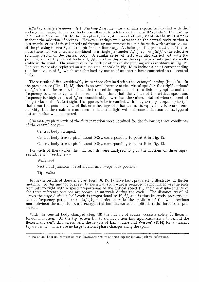
Effect of Bodily Freedoms.--S.l. Pitching Freedom.-In a similar experiment to that with the'rectangular wings, the central body was allowed to pitch about on axis 0·2co behind the leadingedge, but in this case, due to the sweepback, the system was statically stable in the wind streamwithout the addition of springs. However, springs were attached to the central body so that. asystematic series of criti'cal speed and frequency measurements could be made with various valuesof the pitching inertia I (X and the pitching stiffness m(X. As before, in the presentation of the results these two variables are combined in a single parameter I (x' (= I (X-m(X/4n 2f c2
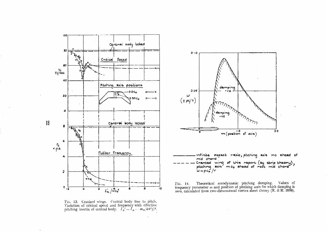
) , the effectivepitching inertia of the central body. A similar series of tests was also carried out with thepitching axis of the central body at 0·39c o, and in this case the system was only just staticallystable in the wind. The main results for both positions of the pitching axis are shown in Fig. 12.The results are also replotted on a much smaller scale in Fig. 13 to include a point correspondingto a large value of I (x' which was obtained by means of an inertia lever connected to the centralbody.
These results differ considerably from those obtained with the rectangular wing (Fig. 10). Inthe present case (Figs. 12, 1~~), there is no rapid increase of the critical speed in the neighbourhoodof I (x' 0, and the results indicate that the critical speed tends to a finite asymptote and thefrequency to zero as I (x' tends to 00. It is noticed that the values of the critical speed andfrequency for high values of I (x' are considerably lower than the values obtained when the centralbody is clamped. At first sight this appears to be in conflict with the generally accepted principlethat from the point of view of flutter a fuselage of infinite mass is equivalent to one of zeromobility, but the results are not seen in their true light without some indication of the type offlutter motion which occurred.
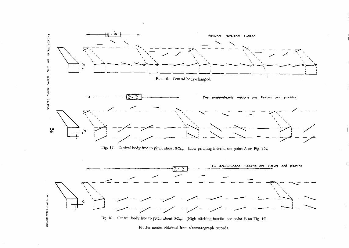
Cinematograph records of the flutter motion were obtained for the following three conditionsof the central body:-
Central body clamped.
Central body free to pitch about 0·2c o, corresponding to point A in Fig. 12.
Central body free to pitch about 0·2c o, corresponding to point B in Fig. 12.
For each of these cases the film records were analysed to give the motions of three repre-sentative wing sections:-
Wing root.
Section at junction of rectangular and swept back portions.
Tip section.
From the results of these analyses Figs. 16, 17, 18 have been prepared to illustrate the fluttermotions. In this method of presentation a half-span wing is regarded as moving across the pagefrom left to right with a speed proportional to the critical speed V c' and the displacements ofthe three reference sections are shown at intervals during the cycle. The distance travelledacross the page during a half cycle is proportional to V c/2fc and is thus inversely proportionalto the frequency parameter os:: 2nfcc/Vc in order to make the motions of the wing sectionsmore obvious the amplitudes are exaggerated but the correct amplitude ratios have been preserved.
'With the central body clamped (Fig. 16) the flutter, of course, consists solely of flexuraltorsional motion. At the tip section the torsional motion lags approximately nJ4 behind theflexural motion*, this agrees with the results of Lambourne and Weston" (1944) for a straighttapered wing. There are no large torsional phase changes along the span.
* Based on the usual convention that downward flexure and nose-up torsion are positive deflections.
8
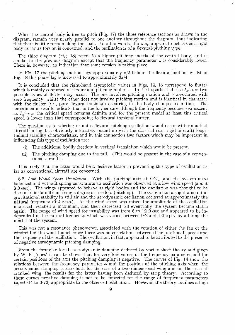
When the central body is free to pitch (Fig. 17) the three reference sections as drawn in thediagram, remain very nearly parallel to one another throughout the diagram, thus indicatingthat there is little torsion along the span. In other words, the wing appears to behave as a rigidbody as far as torsion is concerned, and the oscillation is of a flexural-pitching type.
The third diagram (Fig. 18) refers to a higher pitching inertia of the central body, and issimilar to the previous diagram except that the frequency parameter w is considerably lower.There is, however, an indication that some torsion is taking place.
In Fig. 17 the pitching motion lags approximately n/2 behind the flexural motion, whilst inFig. 18 this phase lag is increased to approximately 3n/4.
It is concluded that the right-hand asymptotic values in Figs. 12, 13 correspond to flutterwhich is mainly composed of flexure and pitching motions. In the hypothetical case I (X" -* 00 twopossible types of flutter may occur. The one involves pitching motion and is associated withzero frequency, whilst the other does not involve pitching motion and is identical in characterwith the flutter (i.e., pure flexural-torsional) occurring in the body clamped condition. Theexperimental results indicate that in the former case although the frequency becomes evanescentas I (X'-+ 00 the critical speed remains definite and for the present model at least this criticalspeed is lower than that corresponding to flexural-torsional flutter.
The question as to whether or not a flexural-pitching oscillation would occur with an actualaircraft in flight is obviously intimately bound up with the classical (i.e., rigid aircraft) longitudinal stability characteristics, and in this connection two factors which may be important ininfluencing this type of oscillation are:-
(i) The additional bodily freedom in vertical translation which would be present.
(ii) The pitching damping due to the tail. (This would be present in the case of a conventional aircraft).
It is likely that the latter would be a decisive factor in preventing this type of oscillation asfar as conventional aircraft are concerned.
8.2. Low Wind Speed Oscillation.-With the pitching axis at 0'2co and the system massbalanced and without spring constraints an oscillation was observed at a low wind speed (about8 ft/sec). The wings appeared to behave as rigid bodies and the oscillation was thought to bedue to an instability in a single degree of freedom (pitching). The system had a slight amount ofgravitational stability in still air and the aerodynamic oscillation occurred at approximately thenatural frequency (0·2 c.p.s.). As the wind speed was raised the amplitude of the oscillationincreased, reached a maximum, and then decreased till eventually the system became stableagain. The range of wind speed for instability was from 6 to 12 ft/sec and appeared to be independent of the natural frequency which was varied between 0·2 and 1·0 c.p.s. by altering theinertia of the system.
This was not a resonance phenomenon associated with the rotation of either the fan or thewindmill of the wind tunnel, since there was no correlation between their rotational speeds andthe frequency of the oscillation. The oscillation, in fact, appeared to be attributed to the presenceof negative aerodynamic pitching damping.
From the formulae for the aerodynamic damping deduced by vortex sheet theory and givenby W. P. Jones6 it can be shown that for very low values of the frequency parameter and forcertain positions of the axis the pitching damping is negative. The curves of Fig. 14 show therelations between the frequency parameter wand the position of the pitching axis when theaerodynamic damping is zero both for the case of a two-dimensional wing and for the presentcranked wing, the results for the latter having been deduced by strip theory. According tothese curves negative damping is not to be expected for the range of frequency parameters(wo=0·14 to 0,70) appropriate to the observed oscillation. However, the theory assumes a high
9
!
Reynolds number, whereas the observed oscillation occurred at R=6 X 10⁴ approximately. It is,in fact, quite probable that the phenomenon was associated with a transition of airflow occurringat some critical Reynolds number. Although this oscillation is not considered to have anyimportance as far as practice is concerned, it is hoped to carry out further investigation with arigid wing.
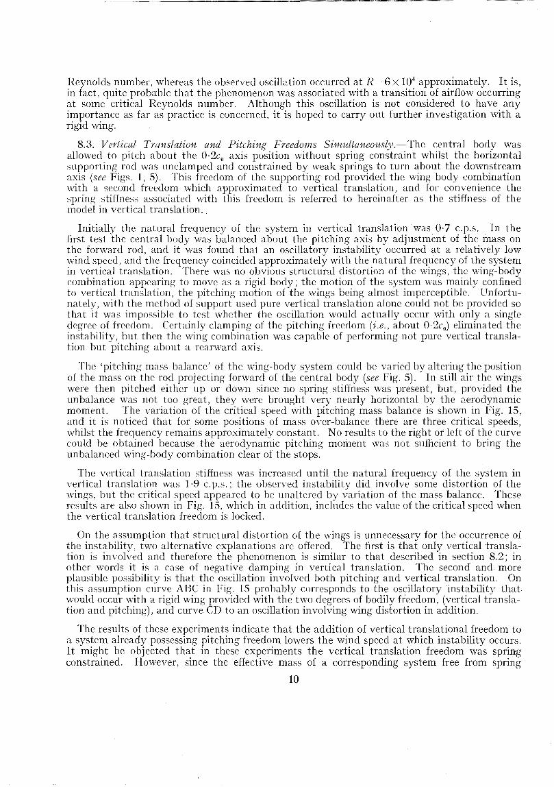
8.3. Vertical Translation and Pitching Freedoms Simultaneously.-The central body wasallowed to pitch about the O·2co axis position without spring constraint whilst the horizontalsupporting rod was unclamped and constrained by weak springs to turn about the downstreamaxis (see Figs. 1, 5). This freedom of the supporting rod provided the wing body combinationwith a second freedom which approximated to vertical translation, and for convenience thespring stiffness associated with this freedom is referred to hereinafter as the stiffness of themodel in vertical translation..
Initially the natural frequency of the system in vertical translation was 0·7 c.p.s. In thefirst test the central body was balanced about the pitching axis by adjustment of the mass onthe forward rod, and it was found that an oscillatory instability occurred at a relatively lowwind speed, and the frequency coincided approximately with the natural frequency of the systemin vertical translation. There was no obvious structural distortion of the wings, the wing-bodycombination appearing to move as a rigid body; the motion of the system was mainly confinedto vertical translation, the pitching motion of the wings being almost imperceptible. Unfortunately, with the method of support used pure vertical translation alone could not be provided sothat it was impossible to test whether the oscillation would actually occur with only a singledegree of freedom. Certainly clamping of the pitching freedom (i.e., about 0·2c u) eliminated theinstability, but then the wing combination was capable of performing not pure vertical translation but pitching about a rearward axis.
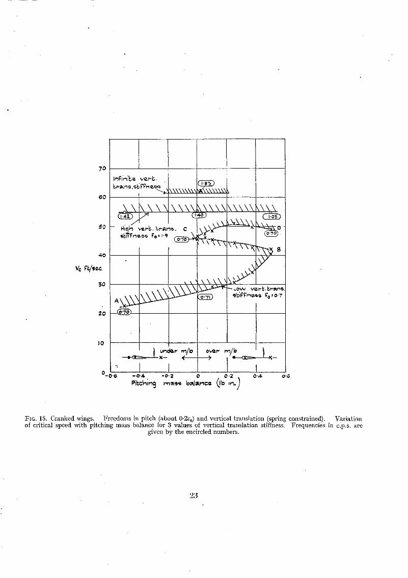
The 'pitching mass balance' of the wing-body system could be varied by altering the positionof the mass on the rod projecting forward of the central body (see Fig. 5). In still air the wingswere then pitched either up or down since no spring stiffness was present, but, provided theunbalance was not too great, they were brought very nearly horizontal by the aerodynamicmoment. The variation of the critical speed with pitching mass balance is shown in Fig. 15,and it is noticed that for some positions of mass over-balance there are three critical speeds,whilst the frequency remains approximately constant. No results to the right or left of the curvecould be obtained because the aerodynamic pitching moment was not sufficient to bring theunbalanced wing-body combination clear of the stops.
The vertical translation stiffness was increased until the natural frequency of the system invertical translation was 1·9 c.p.s.; the observed instability did involve some distortion of thewings, but the critical speed appeared to be unaltered by variation of the mass balance. Theseresults are also shown in Fig. 15, which in addition, includes the value of the critical speed whenthe vertical translation freedom is locked.
On the assumption that structural distortion of the wings is unnecessary for the occurrence ofthe instability, two alternative explanations are offered. The first is that only vertical translation is involved and therefore the phenomenon is similar to that described in section 8.2; inother words it is a case of negative damping in vertical translation. The second and moreplausible possibility is that the oscillation involved both pitching and vertical translation. Onthis assumption curve ABC in Fig. 15 probably corresponds to the oscillatory instability that.would occur with a rigid wing provided with the two degrees of bodily freedom, (vertical translation and pitching), and curve CD to an oscillation involving wing distortion in addition.
The results of these experiments indicate that the addition of vertical translational freedom toa system already possessing pitching freedom lowers the wind speed at which instability occurs.It might be objected that in these experiments the vertical translation freedom was springconstrained. However, since the effective mass of a corresponding system free from spring
10
constraint is proportional to 1- (fa/f) 2 (where fa is the natural frequency and f the frequency ofthe oscillation), the effective mass of the central body may be regarded as approximately zerofor the lower and negative for the higher vertical translation stiffness.
These experiments clearly illustrate the difficulties connected with support systems providingseveral bodily freedoms and indicate the possible close relationship between the problems offlutter and aircraft stability. .
8.4. Rolling Freedom.-Symmetrical flutter occurred at 83 ft/sec* both when all the bodilyfreedoms were locked and when the central body was free to roll without spring constraint.During the latter experiment, due to a slight aerodynamic asymmetry, the wings actuallyrotated continuously about the roll axis at a very slow rate, but this does not affect the result.Springs were then attached to constrain the model in rolling and, for each of the stiffness valuestried, symmetrical flu.tter again occurred at the same wind speed as before.
These tests show that with the introduction of rolling freedom the critical speed for antisymmetrical flutter is raised above that corresponding to the body-locked condition. In theAppendix it is shown that with a tip-to-tip model the critical speed for one type of flutter (i.e.,symmetrical or anti-symmetrical) may be masked by the onset of the other. Although, owingto the presence of symmetrical flutter, the critical speed for anti-symmetrical flutter could not beobserved directly, an attempt was made to deduce that speed by removal of one wing. Thecritical speed measurement for the remaining wing in the body locked condition was repeatedand the speed found to be 8S ft/sec. The rolling freedom was then unlocked so that the winghung vertically in the tunnellike a pendulum. No instability occurred, although the wind speedwas raised to just over 100 ft/sec, and from the behaviour of the wing, which appeared to behighly damped, this speed was judged to be well below the critical speed for flutter. This testconfirms that the critical speed is raised considerably by the introduction of rolling freedom.
9. General Conclusions.-On the Problem of the Flutter of Flying Wings.-The results of theexperiments are in no way conclusive but they do provide evidence to support the following:-
1. The lowest critical speed that will be met in practice will refer to symmetrical flutter.
2. The critical speed calculated on the assumption of immobility of the centre section islikely to be above the critical speed when pitching of the centre section is included.
On the experimental technique.3. Some simplification of the scope of the experiments is necessary and it would be prefer
able to make separate investigations under the following headings:
(i) The influence of bodily freedoms on the flutter of a few models representative ofpresent and possible future practice.
(ii) The influence of sweep (back and forward), elastic stiffnesses, and inertias forcantilever wings (roots fixed).
4. In experiments involving bodily freedoms there are distinct advantages in using ahalf-span model and providing the necessary freedoms at the root (see the Appendix).
10. Acknowledgements.--Acknowledgements are due to Mr. C. Scruton who initiated the designand construction of the model and supporting apparatus, to Mr. C. J. Davis for assistance inmany of the tests, and to Miss N. Belgrave who helped to carry out the analysis of the filmrecords of the flutter motion.
* The critical speed corresponding to the body-clamped condition varied slightly from day to day due to slightchanges in the wing stiffnesses.
11
No. Author
1 R. A. Frazer and W. ]. Duncan2 W. P. Jones ..
3 A. G. Pugsley, ]. Morris andG. A. Naylor
4 H.. A. Frazer
5 J\. C. Lambourne and D. Weston ..
(1 W. P. Jones ..
REFERENCESTitle, etc.
The Flutter of Monoplanes, Biplane and Tail Units. R. & M. 1255. 1931.Antisymmetrical Flutter of a larger Transport Aeroplane. R. & M.
2363. July, 1944.
The effect of Fuselage Mobility in Roll upon Wing Flutter. R. & M.2009. October, 1939.
Note on the Flutter of Flying Wings. A.R.C. 6247. 1942. (Unpublished.)
An Experimental Investigation of the Effect of Localised Masses on theFlutter of a Model Wing. R. & M. 2533. April, 1944.
Summary of Formulae and Notation used in Two-Dimensional DerivativeTheory. R. & M. 1958. 1942.
12
APPENDIX
The use of Tip-to-tip Models
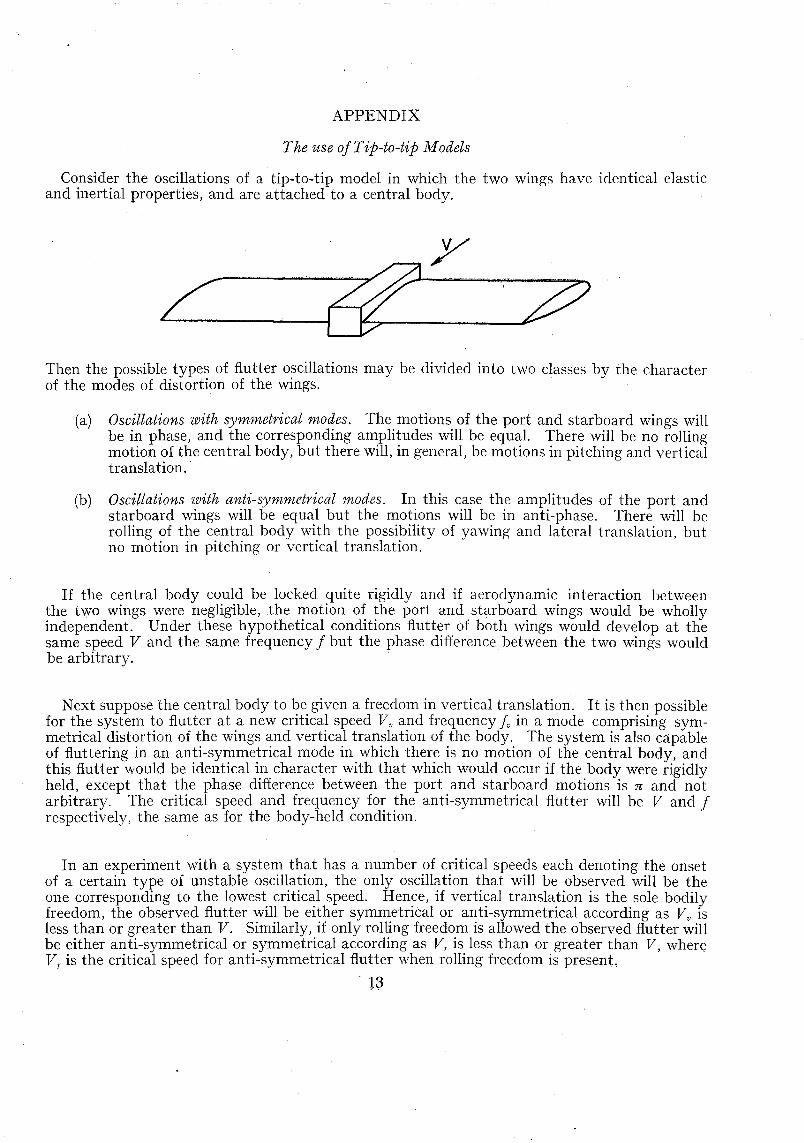
Consider the oscillations of a tip-to-tip model in which the two wings have identical elasticand inertial properties, and are attached to a central body.
/Then the possible types of flutter oscillations may be divided into two classes by the characterof the modes of distortion of the wings.
(a)
(b)
Oscillations with symmetrical modes. The motions of the port and starboard wings willbe in phase, and the corresponding amplitudes will be equal. There will be no rollingmotion of the central body, but there will, in general, be motions in pitching and verticaltranslation.
Oscillations with anti-symmetrical modes. In this case the amplitudes of the port andstarboard wings will be equal but the motions will be in anti-phase. There will berolling of the central body with the possibility of yawing and lateral translation, butno motion in pitching or vertical translation.
If the central body could be locked quite rigidly and if aerodynamic interaction betweenthe two wings were negligible, the motion of the port and starboard wings would be whollyindependent. Under these hypothetical conditions flutter of both wings would develop at thesame speed V and the same frequency f but the phase difference between the two wings wouldbe arbitrary.
Next suppose the central body to be given a freedom in vertical translation. It is then possiblefor the system to flutter at a new critical speed V v and frequency I. in a mode comprising symmetrical distortion of the wings and vertical translation of the body. The system is also capableof fluttering in an anti-symmetrical mode in which there is no motion of the central body, andthis flutter would be identical in character with that which would occur if the body were rigidlyheld, except that the phase difference between the port and starboard motions is n and notarbitrary. The critical speed and frequency for the anti-symmetrical flutter will be V and frespectively, the same as for the body-held condition.
In an experiment with a system that has a number of critical speeds each denoting the onsetof a certain type of unstable oscillation, the only oscillation that will be observed will be theone corresponding to the lowest critical speed. Hence, if vertical translation is the sole bodilyfreedom, the observed flutter will be either symmetrical or anti-symmetrical according as Vv isless than or greater than V. Similarly, if only rolling freedom is allowed the observed flutter willbe either anti-symmetrical or symmetrical according as Vr is less than or greater than V, whereVr is the critical speed for anti-symmetrical flutter when rolling freedom is present,
IS
The above remarks have been based on the assumption that the wings have identical elasticand inertial properties, but in practice this will not be strictly true. However, provided thecharacteristics of the wings are not widely different it will still be possible to classify an oscillationas symmetrical or anti-symmetrical, and the fact remains that for any condition of the centralbody there will in general exist at least one critical speed referring to the onset of symmetricalflutter, and at least one corresponding to anti-symmetrical flutter. Again, in a practical experiment in which the bodily freedoms are clamped there will still exist, due to the clamping notbeing absolute, a slight amount of elastic coupling between the wings, and the flutter whichoccurs may no longer be independent but may be either symmetrical or anti-symmetrical. .
It may be difficult to arrange an experiment to determine the influence of a parameter on oneparticular type of flutter. If, for instance, an attempt is made to find the effect of a certainparameter on the critical speed for anti-symmetrical flutter, and the only body freedom allowedis rolling then any flutter at a speed above the critical speed for the body locked condition willnot be obtained due to the occurrence of symmetrical flutter. One method of overcoming thisdifficulty might be to provide the bodily freedoms appropriate to symmetrical flutter and toadjust the inertias and stiffnesses corresponding to these freedoms so that the critical speed forsymmetrical flutter is raised sufficiently high. However, even apart from the experimentaldifficulties of providing several bodily freedoms simultaneously, it may still be difficult or impossible to eliminate the unwanted type.
These difficulties were in fact encountered in the flutter tests described in this report. 'Whenthe body was allowed the single freedom in pitching, the critical speeds for symmetrical flutterwere (except in one case) found to be lower than the critical speed for the body-clamped condition,and the influence of the pitching inertia of the body on the critical speed for symmetrical fluttercould be investigated. On the other hand when rolling was the only body freedom provided,only symmetrical flutter corresponding to the body clamped condition occurred and no information could be obtained on the critical speed for anti-symmetrical flutter.
For separate investigation of the two types of flutter, it would be preferable to use a half-spanmodel and to provide the appropriate freedoms at the root. In this case if, for instance, onlyrolling freedom is provided at the root, the flutter which occurs can only correspond to the antisymmetrical type. Similarly, if freedom in pitching and vertical translation are provided theobserved flutter can be regarded as symmetrical. Provided the wing is built out from a wallof the wind tunnel, on the theory of images, the air flow of the tests would correctly representsymmetrical flutter. The flow appropriate to anti-symmetrical flutter would, however, not beobtained, but this disadvantage is not considered to be serious.
o
o2
25
o
•2
TABLE 1V alues of aij (in./1b)
where a ij is deflection at position i due to unit load at position j-------
I Port I Starboard----------------i----------I----------T-----,--------j--- --1---1---2--1---3--1--4---'--1---1--2---1--3---1--4-----1------;693-- --0.-903-- --0.-494--1--0.-247-- ----;891--I-l~305----0.-503---O~271-
* The flexural stiffness is here defined as the load which applied at the flexural centre causes unit linear displacement.t This refers to a section in a fore-and-aft plane. .
FIG. 9. Rectangular wings central body free to pitch.Variation of critical speed and frequency with pitchinginertia of central body. (Pitching axis 0·2 chord,Pitching stiffness m rx -r-r 20·4 Ib ft/radn, J