Page 1
An Innovative Umbrella-Type Rotor of Horizontal Axis
Wind Turbine to Regulate Power and Reduce Wind Thrust Wei Xie, Pan Zeng*, Liping Lei
Key Laboratory for Advanced Materials Processing Technology of MOE, Department of Mechanical Engineering,
Tsinghua University, Beijing 100084, China
Tel.: +86-10-62794261
Fax: +86-10-62773637
E-mail address: [email protected]
Abstract
The concept of innovative umbrella-type rotor of horizontal axis wind turbine is proposed in current study.
This rotor type is designed to realize both active power regulation and wind thrust reduction. The rotor is folding
at hub and is pitching and coning coupled due to the inclined folding axis, which resembles the umbrella
configuration. The folding mechanism that aims at refining the loads at hub has also been designed. Wind tunnel
experiments for small rotor models have been conducted to offer data. The rotor performance is estimated in
terms of power coefficient (Cp) and thrust coefficient (Ct). Wind tunnel test result shows that the innovative rotor
effectively regulates Cp and Ct. The highest Cp and Ct are 0.048 and 0.28 respectively, while by regulation the
lowest value are simply 0.009 and 0.16 respectively in current study. It is also found that the regulation
sensitivities are larger in case of larger folding axis incline angle. A constant power output of 0.521 watt in
increasing wind speed is achieved and the fold angle variation relative to wind speed is obtained. In addition, the
innovative rotor is found to bear less thrust than the traditional pitch regulated type, with the maximum reduction
about 7.4% in current study. A detailed load analysis on the proposed folding mechanism has also been
conducted. It is found that moments acting on the hub are converted to the tension mode. The folding
mechanism well refines the loads distribution on hub.
Key words: blade pitch; rotor coning; power coefficient; wind thrust;
1. Introduction
The development of wind turbine is consistently associated with two topics: the power regulation and wind
loads reduction. Power regulation is typically achieved by blade stall and pitch control. New approaches have
been proposed, for example the retractable rotor [1] and blade partial span pitch control [2]. For wind loads
reduction, the DOWEC project proposed a pre-coned upwind rotor with flexible blades [3]. Actually, late in the
last century, aiming at controlling both power and loads, downwind configured, active stall and coning controlled
rotor concept has been raised [4]. The two blades were hinged on the teetering hub through a “three-point
support structure”. Through the rotor coning deflection, the blade span direction aligns with the load direction
and thus the cantilever-based loads are reduced considerably. It is reported that the blade and rotor loads are
reduced between 25% to 50% during operation as well as during stand still in extreme winds.
In current study, an innovative umbrella-type rotor is proposed. This rotor aims to offer a new approach to
regulate power and reduce wind thrust. It is upwind configured and blades are capable to fold upstream at hub
according to wind conditions, which resembles the umbrella configuration. The folding axis, however, is not
perpendicular to the blade span direction, and instead, inclines to it, tilting down to the rotor revolution direction.
Consequently, the rotor is pitching and coning coupled by the folding hinge structurally. The folding axis incline
angle (γ) determines pitching and coning sensitivities theoretically. The proposed rotor is illustrated in Fig. 1.
Page 2
Rotor pitching plays a key role in regulating power and wind thrust, and besides, rotor coning results in swept
area reduction which offers extra wind thrust reduction.
Figure 1: Concept of innovative umbrella-type rotor
A folding mechanism for umbrella-type rotor has been designed elaborately. The mechanism consists of a
hub, an inclined hinge assembling and an actuating structure shown in Fig. 2. The blade is connected to the hub
by the inclined hinge assembling. A screw rod is fixed on the center line of the hub and is driven by the motor.
Once the crew rod rotates, a slider moves linearly along it. This movement is transferred to the blade folding
motion through a link rod as the link rod connects blade root and slider with spherical joints. From the loading
point of view, snice the hinge assembling is incapable in offering torque along the folding axis direction, the huge
bending moment on hub is considerably converted to the tension of the link rod and the compression of the
screw rod. Compared to the blade span dimension, the hub dimension (I) is much smaller. Hence, bending
acting on the hub is sufficiently reduced. In practice, the hub dimension (I), the distance between link support
position and hinge (J) and the screw rod length (K) are determined and optimized according to rotor operation
conditions. Since screw rod is usually designed as short as possible, and tension mode is a favorable load
pattern for link structure, the loads on the hub is believed to be well refined. All the components are covered in a
cowling, avoiding damages from the natural environment.
Figure 2: Schematic diagram of folding mechanism for umbrella-type rotor
The patent authorization of this rotor concept and corresponding folding mechanism design is in process [5].
By conducting wind tunnel experiment, supporting data is obtained to validate the rotor effectiveness in power
and wind thrust regulation. In engineering practice, the detailed rotor aerodynamic analysis is required. In
Page 3
current study, loads on key components of folding mechanism are also analyzed based on a specific condition.
This analysis aims at demonstrating the folding mechanism load-relief property. Further studies are required to
promote this rotor design and development.
2. Experiment setup
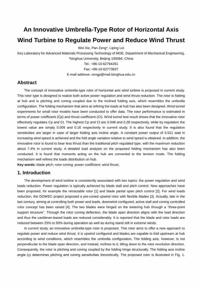
The experiments were conducted in a low speed wind tunnel in Tsinghua University. A rotor test system with
a magnetic brake and sensors to measure revolution rate, torque and wind thrust was set up. A photograph of
the test system is shown in Fig. 3. The tested blade has a length of 0.3 m and is scaled down from the “NREL
PHASE VI” blade with a scaling ratio of 15:1. All the tested rotors were configured with three blades and
possessed a diameter of 0.65 m with a wind tunnel blockage ratio of 14.7%. The original “NREL PHASE VI” rotor
test conditions were not available in current experiment due to facility capacity limits including load and
revolution rate measurement limits. Besides, in the trial test, during pitching process, the power of rotor with
scaled down original blades was found to increase initially and then drop down. As the innovative rotor is
designed to reduce power output consistently during the overall pitching process, the tested blade is pre-pitched
at 18.18°. The modified blade then possesses a much lower Cp (power coefficient) and TSR (tip speed ratio),
meeting the measurement requirements. Since the experiment is to prove the innovative rotor validity in power
and wind thrust regulation, the blade modification including profile scaling down and pre-pitching is believed to
be reasonable. Three hubs with incline angle of 30°, 45° and 60°, a pitch regulated hub and blades were 3D
printed with synthetic resin. The fold angle and pitch angle were adjusted manually and blades were fixed at
desired fold or pitch angle during experiments. A tested rotor in wind tunnel is shown in Fig. 4. The wind thrust
data was collected for the whole turbine including rotor and nacelle, and then the turbine Ct (thrust coefficient)
was calculated. Rotor swept area diminishment due to rotor coning was not taken into account in calculating Cp
and Ct. The blockage correction was considered based on Ref. [6].
Figure 3: Photograph of rotor test system
Page 4
Figure 4: Photograph of tested umbrella-type rotor
The following steps are taken to study the innovative rotor performance. Firstly, turbine Cp and Ct are
measured in wind speed of 4 m/s for rotor with γ of 45°. This experiment is to study the innovative rotor model
aerodynamic performance. Next, in increasing wind speed, the rotors are folded or pitched to regulate power.
This experiment is conducted for rotors with γ of 30°, 45° and 60° and pitch regulated rotor. Then, based on
power regulation experiment data, Cp regulation sensitivity is analyzed for three umbrella-type rotors. Wind
thrust is compared between turbines with umbrella-type and pitch regulated rotors. Turbine Ct regulation
sensitivity is also analyzed. Finally, an umbrella-type rotor with three original “NREL PHASE VI” blades is
modeled and the multi-body dynamic analysis is conducted. The loads distribution on the folding mechanism is
analyzed and the results are also compared to that of an ordinary fixed hub.
3. Results, analysis and discussion
3.1 Power regulation performance of umbrella-type rotor
The turbine Cp and Ct for rotor (γ=45°) in wind speed of 4 m/s are shown in Fig. 5. A drastic drop of both Cp
and Ct, and a shift of TSR to lower range are found as the blade is folded. The turbine highest Cp and Ct are
0.048 and 0.28 respectively for normal rotor, while they drop to 0.009 and 0.16 for rotor with fold angle of 40°.
This rotor behavior is favorable in high wind speed. The decline of Cp and Ct could lead to limitation on power
and wind thrust growth, and low TSR avoids the over speed of rotor. The result shows that the innovative rotor
has potential to achieve both power and wind thrust regulation.
Figure 5: Umbrella-type turbine performance: (a) Cp variation along TSR and (b) Ct variation along TSR
Fig. 6 shows the rotor fold angle variation along wind speed to maintain constant power of 0.521 watt. In the
experiment, the brake torque was fixed and the rotor revolved at 200 RPM constantly. The wind speed was
Page 5
adjusted so that the rotor maintained the constant speed and power output. Results reveal that fold angle
increases with the wind speed. The fold angle adjustment is less in case of larger incline angle. This result
sufficiently demonstrates that the rotor is capable in regulating power and limiting speed growth in high wind
speed.
Figure 6: Fold angle variation along wind speed to maintain constant power
Based on power regulation experiment data, rotor Cp variation along fold angle is analyzed shown in Fig. 7.
For all innovative rotors, Cp decreases with the increase of fold angle. It should be noticed that larger incline
angle leads to more sensitive Cp regulation. At fold angle of 40°, Cp is 0.0024 for rotor with γ of 60°, which is
simply 20.39% to that with γ of 30°. This is due to the fact that larger incline angle leads to higher pitching rate.
The experiment result indicates that incline angle magnitude is the key to Cp regulation sensitivity.
Figure 7: Umbrella-type rotor Cp variation along fold angle
3.2 Investigation on wind thrust acting on umbrella-type rotor
An identical power regulation experiment was conducted for the pitch regulated rotor. Wind thrust data for
turbines with three umbrella-type and pitch regulated rotors are presented in Fig. 8. Under identical operation
conditions, less wind thrust is observed for umbrella-type turbines as compared to pitch regulated type. This
phenomenon corresponds to the distinct rotor coning configuration which is not available for pitch regulated type.
A detailed analysis on the thrust comparison is shown in Fig. 9. As can be seen, the smaller incline angle is, the
less wind thrust the turbine bears. For turbine with γ of 60°, the highest thrust is 98.2% to that of pitch regulated
Page 6
type, yet it is 92.6% for turbine with γ of 30°. This is reasonable as smaller incline angle provides a higher coning
rate. The umbrella-type turbine Ct variation along fold angle is presented in Fig. 10. Similar to Cp, Ct declines
considerably for all tested rotors and the variation is more sensitive in case of larger incline angle. Considering
Fig. 7, Fig. 9 and Fig. 10, for umbrella-type rotor, blade pitching is the key to Cp and Ct regulation sensitivity.
However, under identical Cp conditions, rotor coning provides an extra Ct reduction.
Figure 8: Wind thrust variation along wind speed for tested turbines
Figure 9: Wind thrust ratio of umbrella-type to pitch regulated turbine
Page 7
Figure 10: Umbrella-type turbine Ct variation along fold angle
3.3 Analysis on loads acting on folding mechanism
In order to have an insight on the folding mechanism behavior, an analysis on loads acting on key
components of folding mechanism was conducted. In this analysis, the blade scale and profile is identical to the
“NREL PHASE VI” blade with a length of 5.029 m and a mass of 60.25 Kg. As a modification, the rotor consists
of three blades and the blade pitch angle is fixed at 3°. The hinge incline angle is 45° and each blade is folded at
20°. For folding mechanism geometry, referring to Fig. 2, the rotor hub dimension (I) is determined as 0.33 m
and distance between link support position and hinge (J) is 0.515 m. The screw rod length (K) is 0.54 m.
According to Ref. [7], each blade is divided into 11 segments and the mass and aerodynamic properties are
applied to each blade element. The rotor revolves at 71.63 RPM and the wind speed is fixed at 10 m/s. An
algorithm based on modified BEM (blade element momentum theory) has already been developed by the
authors to calculate the umbrella-type rotor aerodynamic loads. Based on this code and the operation condition,
the rotor aerodynamic loads are obtained. Furthermore, blade gravities and centrifugal forces are obtained and
all these loads are applied to blade elements. By solving the equilibrium equation of the rotor system, the forces
on the hinge axis and the link rod are gained. It is to be noticed that the blade to which the hinge is connected is
straight up originally with blade phase of zero. As a comparison, the blade is also connected to the hub simply
through a fixed connector which possesses an identical orientation as the inclined hinge assembling. The loads
on the inclined hinge and the fixed connector are compared.
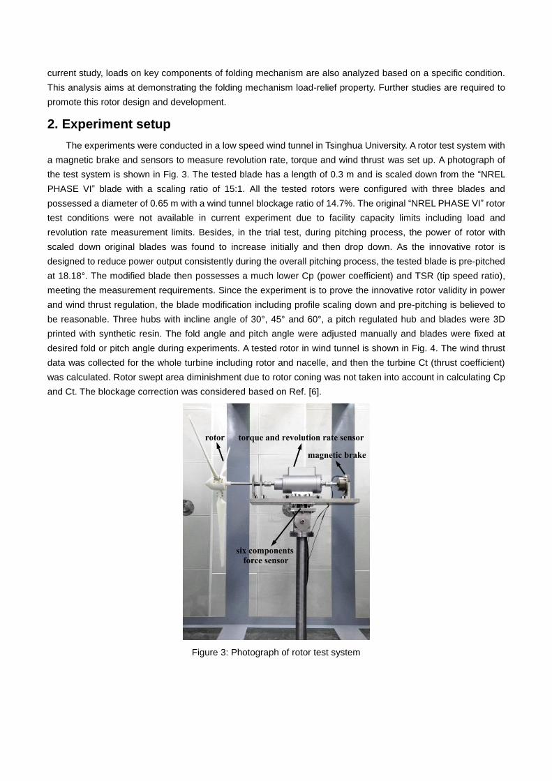
The six force components acting on the hinge and the fixed connector are shown in Fig. 11. The force
direction definition is based on folding axis local coordinate shown in Fig. 2. As can be seen, folding hinge and
fixed connector bear comparable force components of both fx and fy, while a considerable decline of torque tx is
observed in case of folding hinge. This is reasonable since the hinge is incapable of offering torque along its
rotation axis. Similar behavior is observed for torque ty. The highest torque ty acting on folding hinge is -610 Nm
and yet the highest acting on fixed connector reaches 3322 Nm. In addition, folding hinge shows advantages in
alleviating torque along wind speed direction tz. Due to the distinct folding mechanism design, the moment tx
and ty are converted to the tension of link rod. The link rod bears a tension between 14966 N to 17344 N. To be
balanced, the folding hinge consequently bears an additional considerable force fz as shown in Fig. 11. As
mentioned in section 1, the previously proposed downwind coning rotor also utilizes rotor coning and pitching to
regulate power and wind thrust. By coning rotor downwind, this kind of rotor tries to align wind loads along blade
span direction to reduce cantilever loads. However the proposed folding mechanism effectively utilizes the
principle of truss-frame structure to convert torques and moments to tension mode.
Page 8
Figure 11: Loads acting on folding hinge and fixed connector
Conclusion
An innovative umbrella-type rotor concept for power regulation and wind thrust reduction is proposed.
Umbrella-type rotor models were made and wind tunnel experiments were conducted. The turbine Cp and Ct
declined considerably when the blades were folded. The highest Cp and Ct were 0.048 and 0.28 respectively,
while by regulation the highest values were simply 0.009 and 0.16 respectively in current study. Constant speed
of 200 RPM and power of 0.521 watt were achieved with the umbrella-type rotor models in increasing wind
speed. Innovative rotor is more desirable in reducing wind thrust than pitch regulated type. Compared to pitch
regulated rotor, the maximum thrust reduction about 7.4% was found for umbrella-type rotor in current study. In
addition, for innovative rotor, larger incline angle leads to both more sensitive Cp and Ct regulations. A folding
mechanism for umbrella-type rotor is also proposed. Compared to fixed connector between blade and hub, the
moments acting on folding hinge are much less and are converted to the link rod tension mode. The load pattern
for the folding mechanism is favorable.
Acknowledgement
The authors gratefully acknowledge the support of the National Natural Science Foundation of China (No.
51575296).
Page 9
Reference
[1]. Pasupulati SV, Wallace J, Dawson M. “Variable length blades wind turbine”. In: 2005 IEEE Power
Engineering Society General Meeting, San Francisco, USA; 2005.
[2]. Kim T, Kallesøe BS, Friedrich M. “Load reduction for a two-bladed upwind turbine with partial pitch”. In:
European Wind Energy Association (EWEA) offshore conference, Amsterdam, Netherlands; 2011.
[3]. Kooijman HJT, Lindenburg C, Winkelaar D, van der Hooft EL. “Aero-elastic modelling of the DOWEC 6 MW
pre-design in PHATAS”. ECN technical report, DOWEC-F1W2-HJK-01-046/9; 2003.
[4]. Rasmussen F, Petersen JT, Vølund P, Leconte P, Szechenyi E, Westergaard C. “Soft rotor design for flexible
turbines”. Risø National Laboratory published final report, Contract JOU3-CT95-0062; 1998.
[5]. Chinese invention patent: 201510917639.0 (authorization in process).
[6]. Ryi J, Rhee W, Hwang UC, Choi JS. “Blockage effect correction for a scaled wind turbine rotor by using wind
tunnel test data”. Renewable Energy 2015;79:227-235.
[7]. Jonkman JM. “Modeling of the UAE wind turbine for refinement of FAST_AD”. National Renewable Energy
Laboratory technical report, NREL/TP-500-34755; 2003.