IEEE TRANSACTIONS ON POWER ELECTRONICS, VOL. 28, NO. 8, AUGUST 2013 4013
An Integrated 20-kW Motor Drive and IsolatedBattery Charger for Plug-In Vehicles
Saeid Haghbin, Kashif Khan, Shuang Zhao, Mats Alakula, Sonja Lundmark, and Ola Carlson
Abstract—For vehicles using grid power to charge the battery,traction circuit components are not normally engaged during thecharging time, so there is a possibility to use them in the chargercircuit to have an on-board integrated motor drive and batterycharger. An isolated high-power three-phase integrated motordrive and charger based on a split-phase permanent magnet motoris presented in this paper. The motor winding connections are re-versible by a relay-based switching device for traction and batterycharging. In traction mode, the motor is a classical three-phasemotor, but in charging mode it is a rotating isolating transformerproviding a three-phase voltage source for the inverter to chargethe battery. A mathematical model of the motor with six statorwindings is presented for an arbitrary phase shift in windings.For the charging mode, the split-phase motor grid synchronizationprocess and charge control are explained including the developedcontroller. A 20-kW system is designed and implemented to ver-ify the proper operation of the proposed system. Simulation andpractical results are provided to show the system performance interms of functionality, dynamic response, and efficiency. Moreover,some discussions, recommendations, and limitations are providedto give more practical insights.
Index Terms—Integrated motor drive and battery charger, iso-lated battery charger, plug-in vehicles, split-phase permanent mag-net (PM) motor model, winding reconnection.
I. INTRODUCTION
THERE are two types of battery chargers for electric ve-hicles (EVs) or plug-in hybrid electric vehicles (PHEV):
on-board type and stand-alone (off-board) type. The on-boardcharger gives flexibility to charge anywhere where there is anelectric power outlet available. However, the on-board type hasthe drawback of adding weight, volume, and cost to the ve-hicle; thus, it is usually made for lower powers (<3.5 kW).When higher charging power is needed, the size and weightof the charger are easier to handle with an off-board charger.High-power on-board chargers are attractive only if the weight,volume, and cost can be handled. In that case, the infrastruc-ture requirement would be reduced to rather simple high-power
Manuscript received April 16, 2012; revised August 17, 2012 and October12, 2012; accepted November 10, 2012. Date of current version January 18,2013. This work was supported in part by the Swedish Energy Agency and inpart by the Swedish Hybrid Vehicle Center. Recommended for publication byAssociate Editor K. M. Ralph.
K. Khan and S. Zhao are with the Division of Electrical Machines and PowerElectronic, Royal Institute of Technology, Stockholm 10044, Sweden (e-mail:[email protected]; [email protected]).
M. Alakula is with the Lund University, Lund SE-221 00, Sweden (e-mail:[email protected]).
Color versions of one or more of the figures in this paper are available onlineat http://ieeexplore.ieee.org.
Digital Object Identifier 10.1109/TPEL.2012.2230274
outlets, and thus, the cost of these would be significantly lowerthan that of off-board chargers.
During charging time, the vehicle is not driven and duringdriving time it is not intended to charge the battery pack exceptfor regeneration at braking. Thus, it is possible to use the tractiondrive system components in the charger circuit to reduce thesystem components, space and weight, which is equivalent to acost reduction. This is what is referred to as an integrated motordrive and battery charger in this paper.
The battery charger can be galvanically isolated or noniso-lated from the utility grid. Although isolation is a very favorableoption in the charger circuits for safety reasons [1], [2], it isusually avoided due to its cost impact on the system. Differenttypes of integrated chargers are reported by academia or indus-try [2]–[34] that are reviewed and compared in [2]. One of theproposed schemes is an isolated high-power integrated motordrive and battery charger based on a split-winding permanentmagnet (PM) motor [2]–[4].
In a two-pole three-phase PM ac motor, there are three wind-ings in the stator shifted 120 electrical degrees. For the proposedcharger, the windings are divided into two equivalent parts andmoreover they are shifted symmetrically around the stator pe-riphery. Basically, there will be six windings inside the statorinstead of three for a two-pole machine. These six windingscan be considered as two sets of three-phase windings that areshifted. One set is connected to the inverter and another setis connected to the utility grid after synchronization for thebattery charging. This six-winding device acts as an isolatedthree-phase power source after connecting to the grid, enablingbattery charging by the full utilization of the inverter. The circuittopology is a three-phase boost rectifier in this case.
The proposed charger is a high-power isolated device withunity power factor operation capability. Moreover, bidirectionaloperation is feasible so it is possible to feed back power tothe grid from the battery if needed. The charging power is halfof the traction power that is basically the motor thermal limit.Consequently, high power charging (fast charging) is feasiblein this configuration. The motor is rotating during charge op-eration to eliminate high magnetization currents compared toother isolated integrated chargers [17]. An extra clutch is usedto disconnect the motor from the mechanical transmission dur-ing the charge operation. Moreover, the motor-rated losses needto be tolerated for the charging. Hence, the system efficiency inbattery charging mode will be naturally lower than the systemefficiency in traction mode.
The main contribution in this paper compared to the previousworks [2]–[4], [35] is as follows: the six-phase motor model isextended to cover an arbitrary phase shift between the two sets of
4014 IEEE TRANSACTIONS ON POWER ELECTRONICS, VOL. 28, NO. 8, AUGUST 2013
Fig. 1. Electrical traction in a vehicle.
Clutch
BatteryInverter and
Windings Switching Device
Clutch
Internal Combustion Engine
ElectricMotor
Transmission Differ-ential
FuelTank
CO
UP
LE
R
Fig. 2. Simplified schematic diagram of a PHEV using a galvanic-isolatedintegrated charger.
the three-phase windings, the synchronization and charge con-trollers are replaced by a single controller that is more simple forpractical implementation, and a 20-kW system is explained andimplemented for the proposed system that is presented includingexperimental results. Moreover, the motor design and the sys-tem in traction mode are addressed too. In [4], the phase shiftbetween two sets of three-phase windings is π/6 and in [35] thephase shift is zero that means the windings are not shifted andthey are directly divided into two identical parts in the chargingmode.
II. INTEGRATED CHARGER BASED ON A SPLIT-PHASE PMMOTOR WITH RECONNECTABLE STATOR WINDINGS
A traction system based on an ac motor and a three-phase in-verter is shown in Fig. 1. In several schemes, a dc/dc converteris used in the system also [36]. The battery power is transferredto the motor through the inverter. Bidirectional operation of theinverter allows energy restoration to the battery during braking.The main available components that can be used in the chargercircuits are the inverter (switches and diodes), the dc-bus capaci-tor, machine (as inductors or transformer), measurement sensors(usually phase currents and dc-bus voltage), and the controller.
Fig. 2 shows a simple schematic diagram of the proposedintegrated charger system for a PHEV. The proposed schemecan also be used for other type of vehicles using grid power tocharge the battery, like EVs. The motor may be a PM motor andit should have double stator windings.
A
B
C
+
-Vdc
Three-PhaseGrid Source
A
B
C
or
Contactor
Fig. 3. Simplified system diagram in charging mode.
The machine windings are rearranged for the traction andcharging by a controllable relay-based switching device thatis designed for this purpose. Moreover, due to the machinerotation in charging mode an extra clutch is used to disconnectthe machine from the transmission system while charging. Themotor rotation during charging is potentially a disadvantage forthe system since there will be audible noise and increased wear.In order to reduce the mechanical vibrations of the motor, aproportional controller is used during the charge operation.
The main idea is to introduce a multiterminal device calledmotor/generator set to act like a motor in the traction modeand an isolated three-phase power source in the charging mode.The inverter charges the battery by this power source assumingthat proper voltage levels are adopted. With this scheme, theseparate battery charger will be eliminated from the system.The inverter, motor with reconfigured stator windings, and theswitching device (relay based for example) constitute the high-power battery charger.
Fig. 3 shows a simple schematic diagram of the system incharging mode; the system has two modes of operations calledgrid synchronization and charge control. Before connection tothe grid, through the inverter-side stator windings, the batteryand inverter synchronize the voltage at the grid-side windingsto the grid voltage. After grid synchronization, the grid-sidestator windings are connected to grid voltage. Now the inverter-side windings are an isolated three-phase voltage source and theinverter can control the dc voltage and current at the battery side.One control objective is to keep the motor synchronized with thegrid. Another control objective is unit power factor operation.It is showed in [37] that it is possible to have unit power factoroperation while charging.
III. ELECTROMECHANICAL MODELING OF THE
SPLIT-PHASE PM MOTOR
Fig. 4 shows the cross section of a PM motor with splitwindings in the stator. The motor is a PM type that can be apermanent magnet synchronous motor (PMSM), interior per-manent magnet synchronous motor (IPMSM), or PM-assistedtype. The model is developed for IPMSM as a general case sinceit can be used for PMSM or PM assisted also. As is shown inthis figure, there are six windings while the rotor has a two-poleconfiguration. Other number of pole pairs are also possible forthe machine with this integrated charger. These six windingscan be considered as two sets of three-phase windings. Say thata1 , b1 , and c1 are the first set of windings (the same as classicalthree-phase windings) and a2 , b2 , and c2 are the second set ofthree-phase windings. These two sets of three-phase windings
HAGHBIN et al.: INTEGRATED 20-kW MOTOR DRIVE AND ISOLATED BATTERY CHARGER FOR PLUG-IN VEHICLES 4015
Fig. 4. Simplified system diagram in charging mode.
are shifted β electrical degrees (the angle between the magneticaxis of a′
1a1 and a′2a2) in this configuration.
A mathematical model of this machine is developed (seeAppendix A) based on the assumption that all windings magne-tomotive force and rotor magnets are sinusoidally distributed.To model this machine with six stator windings, the induc-tance matrix is first calculated (a 6 × 6 matrix including self-inductances and mutual inductances). Afterward, the flux andvoltage equations are written to model the electrical system [38].The derivative of the coenergy is calculated to obtain the devel-oped electromagnetic torque. The order of system is eight; sixelectrical equations and two mechanical equations in the phasedomain. A special abc to dq transformation is used that is basedon the Park transformation but with an extended version for sixvariables instead of three. The system equations in the dq frameare reduced to a six-order system where all sin and cos termsare eliminated from the equations.
The dynamic model of the electrical part of this machinewith split-stator windings can be described by the followingequations [37] as is calculated in Appendix A:
vd1 = rsid1 +d
dtψd1 − ωrψq1 (1)
vq1 = rsiq1 +d
dtψq1 + ωrψd1 (2)
vd2 = rsid2 +d
dtψd2 − ωrψq2 (3)
vq2 = rsiq2 +d
dtψq2 + ωrψd2 (4)
ψd1 = Ldid1 + Lmdid2 + ψpm (5)
ψq1 = Lq iq1 + Lmq iq2 (6)
ψd2 = Lmdid1 + Ldid2 + ψpm (7)
ψq2 = Lmq iq1 + Lq iq2 (8)
where Ld, Lq , Lmd , and Lmq are the direct and quadrature axiswinding self- and mutual inductances, respectively. Moreover,Ld = Ll + Lmd and Lq = Ll + Lmq . It is assumed that the zerocomponents are zero due to symmetrical three-phase quantities.
Fig. 5. Geometry of the prototype machine.
The developed electromagnetic torque can be expressed as
Te =32
P
2[ψpm (iq1 + iq2 ) + (Ld − Lq )(id1 iq1 + id1 iq2
+ id2 iq1 + id2 iq2 )]. (9)
For a PMSM, with surface mounted magnets, Ld = Lq so thedeveloped electromagnetic torque simplifies to
Te =32
P
2ψpm (iq1 + iq2 ). (10)
IV. PM MOTOR DESIGN
Many different electric machine topologies can be consideredfor the proposed integrated charger. Induction machines (IMs),synchronous reluctance machines (SynRMs), and PM brushlessmachines have all been employed in traction applications andcan be adapted for the integrated charger solution. The perfor-mance comparison, and advantages and disadvantages of thesemachine topologies are reported in the literature [39]–[41].
Based on these comparisons, a three-phase PM-assisted syn-chronous reluctance machine (PMaSynRM) is designed for thisapplication. The SynRMs, which rely on the reluctance of themachine to generate torque, are known to be very cheap andexhibit a reasonable high torque density. However, they are in-ferior to PM machines in terms of torque density and efficiencyand, hence, are not ideal for traction applications which requirea high torque density along with a wide speed range. When themagnets are inserted into an inherently cheap reluctance ma-chine, it results in a higher efficiency and an improved powerfactor [42], [43] for a reasonable cost increase. This topology isreferred to as a PMaSynRM and it is a promising candidate fortraction application.
The geometry of the designed machine is illustrated in Fig. 5.The PMaSynRM is designed following a classical approach inwhich initially the machine geometry is designed to maximizethe reluctance torque and later magnets are introduced to in-crease the torque further. However, the reluctance torque andmagnet torque are equal for this machine and the motor is called
4016 IEEE TRANSACTIONS ON POWER ELECTRONICS, VOL. 28, NO. 8, AUGUST 2013
TABLE IMACHINE DESIGN SUMMARY
Value UnitNumber of phases 3 -Number of poles 4 -Number of slots 24 -Outer stator diameter 180 mmTotal axial length 330 mmRotor outer diameter 112 mmShaft diameter 51 mmAir-gap height 0.35 mmThickness of tangential rib 1 mmMagnet material NdFeB -Rated torque 170 NmRated speed 1500 r/minCurrent density,(rms) 10 A/mm2
IPMSM in the rest of this paper. A transverse laminated rotoris selected because of its low cost and durability. The detailedmachine design and the parametric study are reported in [41].A brief summary of the design is presented in Table I.
V. SYSTEM OPERATION IN TRACTION AND CHARGING MODES
As mentioned earlier, the stator windings are reconnecteddifferently for the traction and charging modes by using somerelays. Fig. 6 shows the main power diagram of the system intraction and charging mode for the four-pole IPMSM motorwith a 20-kW rated power designed for the proposed system.The relay circuit is presented in [4].
A. Traction Mode Operation
For the traction operation, the motor windings are reconfig-ured according to Fig. 6(a). The proposed design is optimizedto obtain high torque and high efficiency in traction mode bymeans of having a salient and PM-assisted rotor. Thanks to thesalient rotor structure, position sensorless control is feasible atall speeds in the traction mode which can reduce the cost andincrease the reliability of the system. At high speeds, back elec-tromotive force (EMF) can be utilized to detect the rotor positionwith fairly high accuracy [44]. At low speeds, a high-frequencycarrier signal is often added on top of the fundamental exci-tation to detect the rotor position based on the rotor saliency.Rotating [45] and pulsating [46] carrier injection strategies arethe most well-known methods to do so. However, due to satura-tion, cross saturation, and slot harmonics, the qualities of bothstrategies are degraded.
To study those impacts in the presented machine, both sen-sorless control strategies are implemented in a separate setupand the experimental results are presented in [47]. In the study,the effects of the saturation and cross saturation are investigatedby means of analytical methods and FEM analysis. A mappingmethod is presented to find the feasible region for sensorlesscontrol using the resulting error signal rather than measuringthe differential inductances. Different compensation methodsare also reviewed and implemented to improve the sensorlesscontrol quality. For the rotating carrier injection strategy, a com-pensation method is presented by one of the authors with respectto the slot harmonic effect which shows a good result in the ex-perimental test.
B. Charging Mode Operation
For the battery charging, the motor windings are reconfig-ured according to Fig. 6(b), while the grid contactor is open.If the motor rotates at the grid synchronous speed with openterminals (open circuit), the induced back EMF due to magnetsis ideally equal to the grid voltage in magnitude. To be able toconnect the motor to the grid, the voltage phase needs to besynchronized with the grid. At the beginning, the inverter drivesthe motor with half of the windings connected to the inverter.After grid synchronization and closing the contactor, the batteryis charged by a proper control action. The whole control for thegrid synchronization and battery charging is done by controllingthe inverter dq currents that is field-oriented control (FOC).
Fig. 7 shows the control strategy of the system in the batterycharging mode. There is a virtual switch indicating the grid syn-chronization or charge control. After winding reconnection, theswitch is positioned in the synchronization mode and the gridcontactor is OFF. In this case, the system is like a normal FOC-based speed control system, but there is no mechanical load. Thedc-bus voltage, two-phase motor currents, iA1 and iB 1 , and therotor position are measured for the speed control. The speed isestimated by using a trigonometric estimator developed for thisapplication. Nevertheless, the grid voltage and motor voltage aremeasured too for the sake of synchronization. After the grid syn-chronization and closing the contactor, the switch will be placedin position 2 automatically (in software) for battery charging.The charge power is controlled by a predefined reference valueof i∗qch that is explained later on.
In an FOC of the PM motor, there is one speed PI controlloop that determines the required reference values for the dqcomponents of the current. Basically, the speed control PI out-put is motor torque requirement. The dq current reference valuesare specified according to the motor type and control strategy.For example, it can be an online calculation or a switching tablesearch approach. For this application, the reference value forthe d component of the current is set to zero in the chargingmode since it is assumed that the motor back EMF is equal tothe grid voltage and there is no need to adjust the motor fluxlevel. The zero d current means that the motor reluctance torqueis not utilized in battery charging mode, which is not necessarybecause there is no mechanical load connected to the shaft.
There are two PI controllers to regulate the currents, id1 andiq1 . The aim of the control is to regulate the dq components ofthe motor currents according to the reference values determinedby the control strategy. To summarize the control strategy todetermine the reference values, id1 is set to zero and iq1 isdetermined by some control action that is different for the gridsynchronization and battery charge control. Moreover, there arefeedforward terms modifying the current controllers outputs toenhance the control performance. The output is a reference valueof the voltage in the rotor reference frame (v∗
d1 and v∗q1). The
dq voltages are transformed to the αβ values by using the rotorposition and aforementioned Park transformation to provide v∗
α1and v∗
β1 for the inverter.For the grid synchronization, the drive system rotates the
motor at the synchronous speed. The produced voltages at the
HAGHBIN et al.: INTEGRATED 20-kW MOTOR DRIVE AND ISOLATED BATTERY CHARGER FOR PLUG-IN VEHICLES 4017
InverterBattery+
-Vdc
A
B
C
InverterBattery+
-Vdc
b1. .b1 b2b2
.c2c2
.a2a2A
B
C
A
B
C
3 PGrid
(a)
(b)N
Contactor
c3 .. c3c4c4
c1 .. c1c2c2
b 3.
.b 3
b 4b 4
b 1.
.b 1
b 2b 2 a3. .a3 a4 a4
a1. .a1 a2 a2
.b4b4
.c4c4
.a4a4
b3
.b3
a1.a1
a3
.a3
c1.c1
c3
.c3
Fig. 6. Practically designed proposed integrated charger with a four-pole and 20-kW rated power IPM motor: (a) traction and (b) charging.
Vdc
Inverter
Split-PhasePM Motor
iB1
iA11di
1qi
*1v
*1v
*1dv*1qv
+0*
1di +
)( 1ddpmr iL
1qqr iL
1di
+*1qi
1qi
+
-
+
-
-
rFeedforward
compensationdq
abc
dq
*r
dtd/-
r
r
Field Oriented Current Control
2av 2bv 2cv
Contactor
abc
2dv 2qv
agv bgv cgv
abc
dgv qgv
3 PhaseGrid
+
-
2dv
dgv+
SynchronousSpeed
dq dqr
PI
PI
PI
P
ChargeCurrent
PI
2: Charge
Synchronization :1
+
+
+
*qchi
-
Phase Synchronization Speed Control
Rotor Oscillation
Control
Fig. 7. System operation in battery charging mode: grid synchronization and charge control.
second set of windings, va2 , vb2 , and vc2 , are ideally the same asgrid voltages, vag , vbg , and vcg , in magnitude. To synchronizethe two sets of the voltages, they are transformed to dq valuesregarding the rotor position. The d component of the voltagesshould be equal and close to zero also for the synchronization.
By slight change of the motor speed, it is possible to change thephase. So, a PI controller is used to use the d component voltageerror to modify the speed reference value. The speed reference isoriginally 2π50 rad/s. However, for the sake of synchronizationit can vary in a range of ±4% of the original value. When the
4018 IEEE TRANSACTIONS ON POWER ELECTRONICS, VOL. 28, NO. 8, AUGUST 2013
Fig. 8. Inverter reference current trajectory during battery charging.
synchronization is finished, the contactor is closed and the gridvoltage is forced to the second set of windings. The virtualswitch changes to position 2 that means the reference value ofi∗q1 is determined by another mechanism that is called chargecontrol.
C. Battery Charge Strategy
As explained earlier, the inverter dq current control is uti-lized to control the battery charging. After closing the contactorand applying the grid voltage to the machine windings, the dqvoltages are not constant despite the fact that the grid voltage isideally constant. The rotor position determines how the constantmagnitude grid voltage is projected in the dq voltages, vd2 andvq2 . To meet unity power factor requirement at the grid side,the following conditions should be satisfied: vd2 = K id2 andvq2 = K iq2 where the constant K determines the load power.Because of grid dq voltage dependence to the rotor angle, themotor dynamical equations (1)–(9) (the double dq model) aresolved to obtain the reference currents. By using MATLAB,these equations are solved for a PM motor, which parametersare presented later on to extract the inverter dq reference cur-rents, id1 and iq1 . The results of the reference current trajectoryare shown in Fig. 8. In the proposed charge control strategy, thepower control needs another control mechanism to be convertedto the dq current control which is a function of motor param-eters. This control stage, power to current, can be an onlineestimator or a lookup table.
The transferred active power from the inverter to the motorcan be written as p = 3
2 vq1iq1 by the assumption of id1 = 0.So, as is shown in this equation, the power can be controlled bycontrolling iq1 . However, there might be rotor oscillations dur-ing transients. A separate P controller is used in the scheme toavoid this problem. The speed error from the synchronous speedis accumulated to the charge current to make the power levelchange smoothly. By changing the d component of the current,id1 , it is possible to control reactive power too. Moreover, thecondition id1 = 0 implies that there is no need to change the dcurrent in the synchronization and charge mode which makesthe implementation easier.
Fig. 9. Experimental setup including the vehicle.
For the grid synchronization, the phase angle synchronizationis much more important than the amplitude synchronization. Forexample, if the motor voltage is within 20% of the grid voltagebut with the synchronized phase, it is safe to close the contactor.There will be some magnetization current to compensate thevoltage difference in this case.
VI. DESIGN, SIMULATION AND IMPLEMENTATION OF A 20-KWEXPERIMENTAL SYSTEM
To verify and assess the proposed integrated motor drive andisolated battery charger, a practical setup is designed and im-plemented based on a 20-kW split-phase IPMSM. To studythe electromagnetic compatibility (EMC) and to have a systemcloser to the real situation, the whole setup except the controlleris installed inside a vehicle. The dSPACE DS1103 controller isused in the setup which is a real-time fast prototype developingcontrol system. The controller and some auxiliary devices areinstalled on a stand-alone rack placed beside the vehicle. Fig. 9shows the developed experimental system that is explained indetail at the following.
HAGHBIN et al.: INTEGRATED 20-kW MOTOR DRIVE AND ISOLATED BATTERY CHARGER FOR PLUG-IN VEHICLES 4019
Split-Phase PM Motor(Double Stator Windings)
with Winding Reconnection Rlays
Inverter
CDC Source
Contactor
Three-PhaseGrid Supply
S1,2,3
Resolver
RDC Board
DigitalAngle
Currents Measurement
Board
iA1 iB1
VoltagesMeasurement
Board
vA2 vB2
VoltagesMeasurement
Board
vA grid vB grid
Voltages Measurement
Board
Vdc
InverterDriver Boards &
Optical Fibers
dSPACE DS1103 Controller
A
C
B
PC
Currents Measurement
Board
idc
Currents Measurement
Board
iA2 iB2
Fig. 10. Block diagram of the experimental system: integrated motor drive and battery charger.
A. Main Structure of the Practical System
Fig. 10 shows a basic diagram of the experimental system.The main parts of the system are the motor, the inverter, therelay-based switching device for the motor winding reconnec-tion, the controller, the measurement devices and interfaces, theprotection systems, and some auxiliary devices. For the sake ofsystem study, different ac and dc digital and analog signals aremeasured or controlled including the motor speed.
The motor is installed under the vehicle that is a Ford Escapeprovided and prepared by Volvo Cars Corporation. The motoris connected to a mechanical brake that makes it possible toload the motor by pressing the brake pedal. The inverter, theswitching device, the voltage/current measurement devices, andsome other circuits are installed in a box mounted inside thevehicle over the motor. Fig. 11 shows the motor installation andFig. 12 shows the box including the inverter, relays, and othercircuits.
B. Motor and Inverter
The motor is a water-cooled four-pole IPMSM machine thatis designed and optimized for this application. The motor poweris 20 kW in traction mode with a possibility to reconnect thewindings for charging. The maximum charging power limit isideally 10 kW that is mainly due to the motor thermal limit. Thedc-bus voltage (battery voltage) is 350 Vdc in this case. Themotor parameters for the three-phase windings connected to theinverter and with a winding arrangement according to Fig. 6(b)are summarized in Table II.
A water-cooled inverter is designed and implemented basedon the Mitsubishi PM600DSA060 intelligent power modules
Fig. 11. Motor installation inside the vehicle.
Fig. 12. Installed panel inside the vehicle including the inverter, switchingrelays, sensors, and so on.
4020 IEEE TRANSACTIONS ON POWER ELECTRONICS, VOL. 28, NO. 8, AUGUST 2013
TABLE IIELECTRIC MOTOR PARAMETERS
Value UnitRated power 20 kWRated speed 1500 r/minNo of poles 4 -Permanent magnet flux 0.27 WbStator resistance 0.3 Ohmd-axis inductance 14.9 mHq-axis inductance 39.9 mHInertia 0.04 Kg.m2
Viscous friction coefficient 0.01 Nm.s/rad
(IPMs). Each module includes two insulated-gate bipolar tran-sistor (IGBT) devices and antiparallel diodes that is one legof the inverter. The modules are capable of handling 1200 Awhile withstanding 500 Vdc. Built-in control circuits provideoptimum gate drive and protection for the IGBT and free-wheeldiode power devices. Each IPM has a built-in protection logicproviding the short-circuit protection, overcurrent protection,overtemperature protection, and undervoltage protection. How-ever, to reduce the impact of the environment noises to the gatesignals, an optical cable is used between the controller and IPMsincluding related hardware and supplies.
C. Position Measurement Using a Resolver
The rotor position is measured using a resolver installed onthe motor shaft, and a resolver-to-digital converter (RDC). Theresolver is composed of three coils: one excitation coil mountedon the rotor and two pick up coils mounted on the stator with 90◦
shift from each other. A printed circuit board (PCB) is designedand implemented for the position measurement. The excitationsignals, angle measurement processing, and angle analog todigital conversion are provided by the RDC. To read the digitalrotor angle, a digital request signal is sent to the board by thecontroller that starts the angle conversion. Consequently, theangle data that are a digital word will be available at the RDCbuffer ports.
The sinusoidal reference wave, that has a frequency of 6.6 kHzin this case, can be adjusted by the user by setting some jumpersand changing some circuit components of the RDC. The refer-ence signal is applied to the resolver’s rotor coil and the inducedvoltage in the stator coils is sent back to the RDC. The RDCboard processes these signals and obtains the rotor angle bythe use of an AD2S83 converter. Afterward, the analog signalcontaining the angle is translated into a digital word with a se-lectable resolution of 10, 12, 14, or 16 bits. Finally, the RDCboard sends the digital word that is 12 bits in this case to thedigital I/O port of the dSPACE controller.
To tune the measured angle, the motor was rotated by anothermotor as a generator while the terminals were open. The mea-sured back EMF was used to adjust the measured position byadding an offset. However, by looking at the motor dq voltage inthis situation it is possible to do this calibration. For the afore-mentioned dq transformation and rotor angle definition, the dvoltage is zero in this case. As is mentioned earlier, this principleis used to perform the grid synchronization by comparing the dvoltages of the motor and the grid.
D. dSPACE Controller
The control is implemented using dSPACE 1103. This rapidcontrol prototyping system consists of both hardware and soft-ware. The hardware is composed of the CP1103 controller boardwith analog and digital I/O. The analog I/O can send or receivesignals within the range of ±10 V and the digital I/Os operatewithin the transistor–transistor Logic (TTL) range. All signalsin CPL1103 can be monitored by status LEDs.
Using the dSPACE real-time interface (RTI), it is possible tofully develop the programs from the Simulink block diagram en-vironment. So, the whole software is developed in the Simulinkenvironment. The PWM frequency of the FOC is 11 kHz that issynchronized to the voltage and current measurement instants.This synchronization is vital to have a robust control systemespecially for the current control loops.
E. Electrical Measurement Interfaces
To measure the voltages, voltage transducer boards with anisolation amplifier AD210JN are used. The input voltage is re-duced by a resistor ladder to a proper dSPACE value of ±10 V.The transducers are designed to convert ±400 to ±10 V. After-ward, the signal will reach the output of the transducer throughan isolation amplifier that protects the dSPACE system againstover voltages.
For the current measurements, LEM LT300-S current trans-ducers are used. This device comes with galvanic isolationbetween the primary and secondary circuits and it provides asecondary current proportional to the measured current. Thissecondary is equipped with a resistor to make sure that the sig-nal at the receiving end of the dSPACE is always kept withinthe range of ±10 V.
The output signal reaches a printed board that compares theactual value of the current with a limit value set by the user. Incase that the measured value exceeds the limit, the device gen-erates an error signal that stops the PWM pulses, and, therefore,the whole system. Fig. 13 shows the stand-alone rack contain-ing the dSPACE I/O interface, the PWM protection units, someauxiliary devices such as power supplies and some distributionterminals.
F. Software Development and Control Implementation
The whole control program is performed in Simulink. Themain reason was to be able to study and investigate differentaspects of the system. For example, it is possible to change acontroller gain in real time while the motor is running. How-ever, in the software there are more blocks such as saturation,integrator antiwindups, filters, and so on that are not explainedhere. There are both automatic and manual control on someparts of the system for the protection purposes. For example, itis possible to connect/disconnect the grid contactor by softwareor manually.
During the system design, more quantities than necessaryones were measured for study purposes. For example, both thedc-bus current and voltage are measured by the system. So, it ispossible to see the system efficiency online.
HAGHBIN et al.: INTEGRATED 20-kW MOTOR DRIVE AND ISOLATED BATTERY CHARGER FOR PLUG-IN VEHICLES 4021
Fig. 13. Standalone rack including the dSPACE interfaces, resolver, fast pro-tection, and other auxiliaries.
The measurement capture is synchronized with the pulse-width modulation (PWM) pulses to ensure data validity. Af-ter measurement, a software programmed interrupt initiates thecontrol process. First, the speed regulator and then the currentsregulators will operate to generate a voltage vector. This vectorresults into a PWM duty cycle by means of the PWM3 RTIblock. One important issue is that current measurement shouldbe synchronized with PWM signals. If the current measurementis happening during the inverter switching, the measured valueincludes some noises that can drastically degrade the systemperformance. The current controllers are the fastest dynamicsin the system that needs some special attention. The angle mea-surement was reduced to 1.1 kHz due to the RDC design.
G. Simulation Results
The whole system has been simulated by the use of MATLAB/Simulink software based on the aforementioned system equa-tions. The ideal converter is used in the simulation (no PWMor SVM is used for the inverter). Before simulation starts, it isassumed that the system is reconfigured for charging but thegrid contactor is open. The charging process starts when theinverter starts to rotate the motor by the means of battery andinverter-side motor windings. The motor then rotates at the gridsynchronous speed.
When the motor speed is close to synchronous speed, it isassumed that the motor voltage magnitude is close to the gridvoltage magnitude, but the phases may not be identical. After-ward, the voltage phase is adjusted by speed control of the motor(equivalently torque control). This control action is provided bycontrolling the q component of the current in this case. After ad-justing both voltage amplitude and angle, the contactor is closed
0 2 4 6 8 10 12 14−1000
−500
0
500
1000
1500
2000
2500
3000
Time (s)
Po
wer
(W
)
Fig. 14. Simulation result: grid power to the charger system.
0 2 4 6 8 10 12 140
50
100
150
200
250
300
350
Time (s)
Sp
eed
(ra
d/S
ec)
Fig. 15. Simulation result: electrical speed of the motor/generator.
and the machine grid-side windings are directly connected to thegrid. At this moment, the system starts to charge with a powerlevel of 2 kW. In order to show the system transient response,the charge power is reduced to −500 W after 5 s.
System operation during different time intervals can be sum-marized as (see Figs. 14–21) follows:
1) t = 0 till t = 0.8 s: The speed is regulated close to thesynchronous speed, 2π50 rad/s. The system is in synchro-nization mode and the contactor is open.
2) t = 0.8 till t = 5 s: The grid side windings voltage issynchronized to the grid voltage (phase synchronization).The system is in synchronization mode and the contactoris open.
3) t = 5 till t = 10 s: Synchronization is finished and thecontactor is closed at t = 5 s. Then, the dc bus is chargedwith a 2 kW power level.
4) t = 10 till t = 14 s: At time t = 10 s the charge powerlevel is commanded to −500 W. The system is chargingwith −500 W which is battery decharging.
Fig. 14 shows the power from the grid to the charger system.At first, while the motor/generator is in synchronization mode(the first five seconds), the grid power is zero. Then, the contactoris closed and charging is started (t = 5 s) with a power levelof 2 kW. After five seconds (t = 10 s), the charging power isreduced to−500 W. The electrical speed is shown in Fig. 15. Asis shown in this figure, the rotor speed oscillations are dampedquickly by the proper operation of the controller that is a Pcontroller which is presented in Fig. 7 and explained before.
4022 IEEE TRANSACTIONS ON POWER ELECTRONICS, VOL. 28, NO. 8, AUGUST 2013
0 2 4 6 8 10 12 14−15
−10
−5
0
5
10
15
Time (s)
To
rqu
e (N
m)
Fig. 16. Simulation result: motor/generator torque during charge time.
4.97 4.98 4.99 5 5.01 5.02 5.03−200
−150
−100
−50
0
50
100
150
200
Time (s)
Mo
tor
and
gri
d v
olt
ages
(V
)
Fig. 17. Simulation result: phase A of the motor and grid voltages during thesynchronization and contactor closing time.
The motor/generator torque is shown in Fig. 16. The ma-chine develops constant torque in the first 0.68 s to increase thespeed to become close to the synchronous speed (2π50 rad/sin this case). Then, there are some oscillations around timest = 0.68 s and t = 1.2 s. In this time interval, the motor volt-age is synchronized with the grid voltage. Moreover, beforeclosing the contactor, there is a short delay in the software tomake sure that the motor voltage is stable. In addition, there aresome oscillations in torque around the times that the contactoris closed (t = 5 s) and at the step change of the charge powerlevel (t = 10 s). The developed torque compared to its nominalvalue is almost negligible (less than 1%) because there is nomechanical load connected to the machine during charging.
Fig. 17 shows the motor and grid voltage close to the timethat the contactor is closing. As is shown in this figure, themotor voltage is slightly lower than the grid voltage whichafter closing the contactor, the motor voltage is forced to thehigher value, i.e., the grid voltage. This level are very close tothe voltage values used in the experimental system. So, it hasbeen tried to run the simulations close to the practical situation.Higher voltage values enable higher power transfer assumingthat the maximum currents are fixed due to thermal limits. Themotor synchronous speed voltage is not according to what isexpected regarding the initial design goals, so that is the reasonthat instead of 230 V a 100 V voltage is applied to the motor.The voltage difference between the motor and the grid is notcritical for closing the contactor if the difference is not a largevalue. Both simulation and practical results that are explainedlater on confirm that the system is not sensitive to the voltage
0 2 4 6 8 10 12 14−15
−10
−5
0
5
10
15
Time (s)
Ph
ase
A o
f th
e g
rid
cu
rren
t (A
)
Fig. 18. Simulation result: phase A of the grid current during charge operation.
Fig. 19. Simulation result: three-phase grid currents during the start of high-power charging.
9.985 9.99 9.995 10 10.005 10.01 10.015 10.02−15
−10
−5
0
5
10
15
Time (s)
Th
ree−
ph
ase
gri
d c
urr
ent
(A)
Fig. 20. Simulation result: three-phase grid currents during the step change inthe charging power from 2 kW to −500 W.
variations. Some simulation results are shown in [4] describingthe system functionality for the standard defined condition ofthe grid voltage variation in a normal mode or a transient period.
Fig. 18 shows the phase A current of the grid during the wholesimulation time. At first, before closing the contactor, the currentis zero. Afterward, the current increases for the 2 kW chargingand then reduces to the charge power reduction to −500 W.Figs. 19 and 20 show the three-phase currents of the grid duringthe transients.
As is mentioned before, unity power factor operation is possi-ble for the charger. Fig. 21 shows the grid side phase A windingvoltage and current. The current is multiplied by a factor of 20for more figure clarity. The reference value of the d componentof the current id is set to zero. By changing this value, it ispossible to slightly change the power factor. However, here the
HAGHBIN et al.: INTEGRATED 20-kW MOTOR DRIVE AND ISOLATED BATTERY CHARGER FOR PLUG-IN VEHICLES 4023
9.985 9.99 9.995 10 10.005 10.01 10.015 10.02−200
−150
−100
−50
0
50
100
150
200
Time (sec)
Fig. 21. Simulation result: phase A grid voltage (V) and scaled grid current(1/20A) during the step change in the charging power from 2 kW to −500 W.
Fig. 22. Practical result: back EMF voltage of the motor windings in thecharging mode.
value is kept to zero. Due to the voltage drop over the leakageinductance, there is a small phase shift between the phase volt-age and current that the current lags the voltage. After changingthe power level to the negative value of −500 W, the currentphase shift is changed to −π indicating negative power wherethe battery sends power back to the grid.
H. Practical Results and Discussions
To determine the motor flux constant and to evaluate thequality of harmonic contents, the motor back EMF is measuredat different speeds. For example, Fig. 22 shows the measuredthree-phase voltage at synchronous speed while the motor ter-minals are open. This voltage will be connected to the utilitygrid after synchronization in charging mode. For the constructedmotor, the back EMF was lower than expected because of a de-sign error. This voltage needs to be close to the grid voltage;otherwise, a large amount of magnetization current is drawn bythe grid after closing the contactor. However, in this system thegrid voltage is reduced to half of the rated value by using an au-
Fig. 23. Practical result: phase A voltage of the grid and motor during syn-chronization and before closing the contactor.
Fig. 24. Practical result: phase A of the grid voltage and current during thebattery charging operation.
totransformer to match the motor back EMF. So, the motor backEMF needs to be carefully controlled in the design stage forthe proposed system. Moreover, the motor design is optimizedfor the traction mode. As can be seen from the back EMF, theharmonic content is high (the frequency spectrum is not shownhere). In the next generation of the motor design, there will bemore emphasis to the motor performance in the charging mode.
As mentioned earlier, the motor grid-side winding voltagesand the grid voltages are synchronized by adjusting the motorspeed. Fig. 23 shows phase A of the measured motor and gridvoltages during synchronization and before closing the contac-tor. The d component of the motor current is set to zero. Bychanging this value, it is possible to adjust the motor output
4024 IEEE TRANSACTIONS ON POWER ELECTRONICS, VOL. 28, NO. 8, AUGUST 2013
0 0.5 1 1.5 2 2.5 3 3.5 4−15
−10
−5
0
5
10
time (s)
inve
rter
q c
urr
ent
i (
A)
0 0.5 1 1.5 2 2.5 3 3.5 4−5
0
5
10
time (s)
gri
d q
cu
rren
t i
(A
)
Fig. 25. Practical result: system dynamic response to the step change of the charging power.
voltage because of the changing flux. Nevertheless, this voltagevariation cannot be too high and the motor parameters imposesome practical limitations. Some simulation results and discus-sions regarding the grid voltage variations are provided in [4].However, if the motor voltage is not exactly the same as the gridvoltage, after closing the contactor, the motor draws requiredmagnetization current from the grid to reach a steady-state work-ing point at the synchronous speed. If the magnetization currentis too high, the efficiency goes down mainly due to the statorcopper losses.
The measured motor phase A voltage and current at the gridside are shown in Fig. 24 during the battery charging operation.The power factor is very close to 1. By changing the d componentof the current, it is possible to change the power factor.
After closing the contactor, the grid dominates the systembehavior. So basically the grid voltage forces the motor to ro-tate with the synchronous speed. Interesting result is the motorbehavior in the case of inverter PWM blocking. After closingthe contactor and grid connection, the inverter gate signals areturned OFF. The motor will continue to rotate at the synchronousspeed. The motor is stable and it is possible to slightly load themotor as well in this case.
Fig. 25 shows the measured system response to the stepchange of the charging power from a power level of −500 Wto a power level of 1300 W. The inverter current is changedfrom 4 A to −7 A. As is shown in the figure, the dynamic re-sponse is fast (less than half of a second) and the oscillationsare damped quickly where negative (vehicle to grid) to positive(battery charging) operation is depicted.
System performance (efficiency): The system efficiency incharging mode is less than the one in traction mode, becausewith the same amount of loss, the output power is reduced morethan half. The total loss in the charging mode is the inverter lossand the motor loss. The inverter loss is divided into switchingloss and conduction loss for this PWM-based inverter [48], [49]which is a complicated function of the current. For this system,the inverter loss is measured 80 W for the case that the motor is
running at synchronous speed without charging. So, as a roughestimation, 100 W is assumed for the total inverter loss in allcases.
Motor loss is mainly copper loss and iron loss. The ironloss is almost a constant value since the motor is running at aconstant speed which is measured to 200 W for this system. Thecopper loss is a function of output power. For the optimal currenttrajectory that is shown in Fig. 8, the efficiency is calculated tobe 82.7% for a charging power level of 500–3000 W consideringonly the copper loss. However, in the measurement setup id1 = 0and it is different from the optimal case as described earlier.
The measured system efficiency is shown in Fig. 26 for dif-ferent power levels and different grid voltages. The measuredefficiency is slightly lower than the expected one, and the mainreason is the deviation from the optimal current trajectory andinaccurate inverter loss. The efficiency is measured by a Yoko-gawa 1800 family power analyzer from the dc source port to theac line source. For the dc and ac sources, the laboratory sourcesare used. The vehicle battery is not used in this phase of theproject due to safety reasons.
System performance (dynamic response): The charger re-sponse to the load disturbance is an important characteristicof the system. For example, if there is a fault in terms of over-current in a short duration of time, the charger may need tobe able to recover itself after the fault clearance or it may beneeded to shut down the charger and wait for the operator main-tenance. The charger response in these cases are according tothe claimed specifications by the manufacturer or the coveredclass of the related standard [50]. For this application, a vehiclebattery charger, it is not expected to have a step change in theload since the battery is a continuous load. So, it is not expectedto have a step change in the load during the charge operation.Nevertheless, as mentioned earlier, Fig. 25 shows the system re-sponse to a step change in the charging power level of −500 Wto a power level of 1300 W. Usually, the battery is charged witha constant current (bulk charge) and after reaching a certainamount of state of charge, the current control converts to a fixed
HAGHBIN et al.: INTEGRATED 20-kW MOTOR DRIVE AND ISOLATED BATTERY CHARGER FOR PLUG-IN VEHICLES 4025
Fig. 26. Practical result: system efficiency in charging mode for different grid voltages.
voltage mode (holding voltage). So, as is shown in this figure,the charger dynamic response is fast enough in the context ofthe application.
System performance (limitations and improvements): To beable to charge the battery with high power, the controlled inverteroperation is needed. The charging power of 10 kW was thedesign goal. However, the back EMF was not according to whatwas expected (it was half of the desired value). So the chargingpower was limited to 5 kW for this motor. A charge power ofup to 3 kW is tested. After this power level, the rotor started tooscillate. By increasing the system switching frequency, it waspossible to increase the charge level. The dSPACE controllercould not handle more switching frequency in this case. Theharmonic content of the back EMF was a limiting factor. Bylooking to the current waveform, it was realized that the currentwaveform has some nonlinearities that is mainly due to themotor harmonics. So, it is recommended to design the motorwith a waveform closer to sinusoidal in charging mode.
VII. CONCLUSION
An integrated motor drive and isolated battery charger basedon a split-phase PM motor with reconnectable stator windingsis presented for grid-connected vehicles, i.e., EVs or PHEVs.The system structure for the traction mode and charging modeis presented including the motor winding configuration in eachmode. The mathematical model of the split-phase PM motor, asix-phase motor, is extracted for an arbitrary phase shift betweenthe two sets of three-phase windings. The proposed system isverified by an experimental system with a 20-kW PM motorthat is designed and implemented for this purpose. A summaryof the PM motor design and the system operation in tractionmode, along with a detailed explanation of the system operationin the battery charging mode, are presented. The 20-kW experi-mental system is described including some detail explanation ofthe hardware and software components. Simulation and practi-cal results are provided to show that the proposed system has agood performance in terms of functionality and efficiency. Some
discussions, recommendations, and limitations are provided togive more practical insights: efficiency level close to 80% ismeasured in the battery charging mode, the system has a fastdynamic response in battery charging mode, unity power factoroperation is feasible, the PM motor back EMF is an impor-tant design parameter for this application, and motor harmoniccontents need to be improved.
APPENDIX AMATHEMATICAL MODEL OF THE IPMSM WITH SIX
STATOR WINDINGS
The voltage equation for each winding of the motor can bedescribed as
where La1 a1 , Lb1 b1 , Lc1 c1 , La2 a2 , Lb2 b2 , and Lc2 c2 are wind-ings self-inductances. Moreover, La1 b1 , La1 c1 , La1 a2 , La1 b2 ,La1 c2 , Lb1 bc1 , Lb1 c2 , Lc1 b2 , La2 b2 , La2 c2 , and Lb2 c2 are wind-ings mutual inductances. ψpm is the PM flux (the rotor flux) andθr is the angel between the rotor d axis and the magnetic axesof winding a′
1a1 .The inductance values are calculates as [51]
La1 a1 = Lls + Lm − LΔm cos(2θr ) (18)
La1 b1 = Lb1 a1 = −12Lm − LΔm cos2
(θr −
π
3
)(19)
La1 c1 = Lc1 a1 = −12Lm − LΔm cos2
(θr +
π
3
)(20)
La1 a2 = La2 a1 = cosβLm − LΔm cos2(
θr −β
2
)(21)
La1 b2 = Lb2 a1 = cos(
2π
3+ β
)Lm
− LΔm cos2(
θr −π
3+
β
2
)(22)
La1 c2 = Lc2 a1 = cos(
4π
3+ β
)Lm
− LΔm cos2(
θr −2π
3− β
2
)(23)
Lb1 b1 = Lls + Lm − LΔm cos2(
θr −2π
3
)(24)
Lb1 c1 = Lc1 b1 = −12Lm − LΔm cos2θr (25)
Lb1 a2 = La2 b1 = cos(
2π
3− β
)Lm
− LΔm cos2(
θr −π
3− β
2
)(26)
Lb1 b2 = Lb2 b1 = cosβLm − LΔm cos2(
θr −2π
3− β
2
)(27)
Lb1 c2 = Lc2 b1 = cos(
2π
3+ β
)Lm − LΔm cos2
(θr −
β
2
)
(28)
Lc1 c1 = Lls + Lm − LΔm cos2(
θr +2π
3
)(29)
Lc1 a2 = La2 c1 = cos(
2π
3+ β
)Lm
− LΔm cos2(
θr −2π
3− β
2
)(30)
Lc1 b2 =Lb2 c1 =cos(
2π
3−β
)Lm −LΔm cos2
(θr−
β
2
)(31)
Lc1 c2 = Lc2 c1 = cosβLm − LΔm cos2(
θr −π
3− β
2
)(32)
La2 a2 = Lls + Lm − LΔm cos2(θr − β) (33)
La2 b2 = Lb2 a2 = −12Lm − LΔm cos2
(θr −
π
3− β
)(34)
La2 c2 = Lc2 a2 = −12Lm − LΔm cos2
(θr −
2π
3− β
)(35)
Lb2 b2 = Lls + Lm − LΔm cos2(
θr −2π
3− β
)(36)
Lb2 c2 = Lc2 b2 = −12Lm − LΔm cos2(θr − β) (37)
Lc2 c2 = Lls + Lm − LΔm cos2(
θr −2π
3− β
)(38)
where Lm , LΔm , and Lls are the average value of magnetizationinductance, half-amplitude of the sinusoidal variation of themagnetization inductance, and the leakage inductance of eachwinding. It is assumed that all windings have the same numberof turns.
If the 6 × 6 inductance matrix, 6 × 1 current vector, 6 × 1voltage vector, 6 × 1 flux vector, and 6 × 6 resistance matrixare defined as
Ls =
⎡⎢⎣
La1 a1 La1 b1 . . . La1 c2
Lb1 a1 Lb1 b1 . . . Lb1 c2
. . . . . . . . . . . .Lc2 a1 Lc2 b1 . . . Lc2 c2
⎤⎥⎦
is = [ ia1 ib1 ic1 ia2 ib2 ic2 ]T
vs = [ va1 vb1 vc1 va2 vb2 vc2 ]T
ψs = [ψa1 ψb1 ψc1 ψa2 ψb2 ψc2 ]T and
Rs = rsI6 , where I6 is the 6 × 6 identity matrix, the voltageand flux equations can be written as [38]
vs = Rsis +d
dtψs . (39)
The developed electromagnetic torque in the machine can becalculated as [38]
Te =P
2
(12iTs
∂Ls
∂θris + iTs
∂ψpm
∂θr
)(40)
where P is the machine number of poles. ψpm is stator windingfluxes due to rotor magnets. The mechanical dynamical equa-tions describing the machine are
dωr
dt=
P
2J
(Te −
2Bm
Pωr − TL
)(41)
dθr
dt= ωr (42)
where J,Bm , TL , and ωr are the moment of inertia, viscousfriction coefficient, load torque, and speed of the machine,respectively.
To simplify the machine equations, a special version of thePark transformation (it is called extended Park transformation
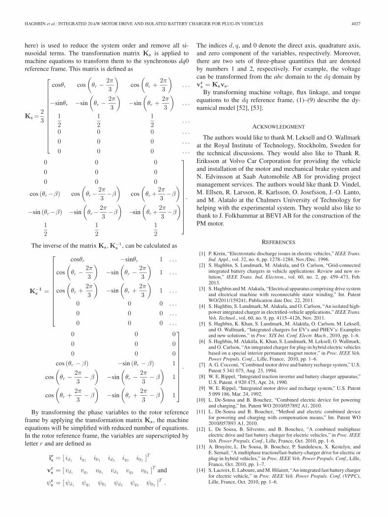
HAGHBIN et al.: INTEGRATED 20-kW MOTOR DRIVE AND ISOLATED BATTERY CHARGER FOR PLUG-IN VEHICLES 4027
here) is used to reduce the system order and remove all si-nusoidal terms. The transformation matrix Ks is applied tomachine equations to transform them to the synchronous dq0reference frame. This matrix is defined as
Ks =23
⎡⎢⎢⎢⎢⎢⎢⎢⎢⎢⎢⎢⎢⎢⎣
cosθr cos
(θr −
2π
3
)cos
(θr +
2π
3
). . .
−sinθr −sin
(θr −
2π
3
)−sin
(θr +
2π
3
). . .
12
12
12
. . .
0 0 0 . . .
0 0 0 . . .
0 0 0 . . .
0 0 00 0 00 0 0
cos (θr−β) cos
(θr−
2π
3−β
)cos
(θr +
2π
3−β
)
−sin (θr−β) −sin
(θr−
2π
3−β
)−sin
(θr +
2π
3−β
)
12
12
12
⎤⎥⎥⎥⎥⎥⎥⎥⎥⎥⎥⎥⎥⎥⎦
.
The inverse of the matrix Ks ,K−1s , can be calculated as
K−1s =
⎡⎢⎢⎢⎢⎢⎢⎢⎢⎢⎢⎢⎢⎣
cosθr −sinθr 1 . . .
cos
(θr −
2π
3
)−sin
(θr −
2π
3
)1 . . .
cos
(θr +
2π
3
)−sin
(θr +
2π
3
)1 . . .
0 0 0 . . .
0 0 0 . . .
0 0 0 . . .
0 0 00 0 00 0 0
cos (θr − β) −sin (θr − β) 1
cos
(θr −
2π
3− β
)−sin
(θr −
2π
3− β
)1
cos
(θr +
2π
3− β
)−sin
(θr +
2π
3− β
)1
⎤⎥⎥⎥⎥⎥⎥⎥⎥⎥⎥⎥⎥⎦
.
By transforming the phase variables to the rotor referenceframe by applying the transformation matrix Ks , the machineequations will be simplified with reduced number of equations.In the rotor reference frame, the variables are superscripted byletter r and are defined as
irs = [ id1 iq1 i01 id2 iq2 i02 ]T
vrs = [ vd1 vq1 v01 vd2 vq2 v02 ]T and
ψrs = [ψd1 ψq1 ψ01 ψd2 ψq2 ψ02 ]T .
The indices d, q, and 0 denote the direct axis, quadrature axis,and zero component of the variables, respectively. Moreover,there are two sets of three-phase quantities that are denotedby numbers 1 and 2, respectively. For example, the voltagecan be transformed from the abc domain to the dq domain byvr
s = Ksvs .By transforming machine voltage, flux linkage, and torque
equations to the dq reference frame, (1)–(9) describe the dy-namical model [52], [53].
ACKNOWLEDGMENT
The authors would like to thank M. Leksell and O. Wallmarkat the Royal Institute of Technology, Stockholm, Sweden forthe technical discussions. They would also like to Thank R.Eriksson at Volvo Car Corporation for providing the vehicleand installation of the motor and mechanical brake system andN. Edvinsson at Saab Automobile AB for providing projectmanagement services. The authors would like thank D. Vindel,M. Ellsen, R. Larsson, R. Karlsson, O. Josefsson, J.-O. Lanto,and M. Alatalo at the Chalmers University of Technology forhelping with the experimental system. They would also like tothank to J. Folkhammar at BEVI AB for the construction of thePM motor.
REFERENCES
[1] P. Krein, “Electrostatic discharge issues in electric vehicles,” IEEE Trans.Ind. Appl., vol. 32, no. 6, pp. 1278–1284, Nov./Dec. 1996.
[2] S. Haghbin, S. Lundmark, M. Alakula, and O. Carlson, “Grid-connectedintegrated battery chargers in vehicle applications: Review and new so-lution,” IEEE Trans. Ind. Electron., vol. 60, no. 2, pp. 459–473, Feb.2013.
[3] S. Haghbin and M. Alakula, “Electrical apparatus comprising drive systemand electrical machine with reconnectable stator winding,” Int. PatentWO/2011/159241, Publication date Dec. 22, 2011.
[4] S. Haghbin, S. Lundmark, M. Alakula, and O. Carlson, “An isolated high-power integrated charger in electrified-vehicle applications,” IEEE Trans.Veh. Technol., vol. 60, no. 9, pp. 4115–4126, Nov. 2011.
[5] S. Haghbin, K. Khan, S. Lundmark, M. Alakula, O. Carlson, M. Leksell,and O. Wallmark, “Integrated chargers for EV’s and PHEV’s: Examplesand new solutions,” in Proc. XIX Int. Conf. Electr. Mach., 2010, pp. 1–6.
[6] S. Haghbin, M. Alakula, K. Khan, S. Lundmark, M. Leksell, O. Wallmark,and O. Carlson, “An integrated charger for plug-in hybrid electric vehiclesbased on a special interior permanent magnet motor,” in Proc. IEEE Veh.Power Propuls. Conf.,, Lille, France, 2010, pp. 1–6.
[7] A. G. Cocconi, “Combined motor drive and battery recharge system,” U.S.Patent 5 341 075, Aug. 23, 1994.
[8] W. E. Rippel, “Integrated traction inverter and battery charger apparatus,”U.S. Patent. 4 920 475, Apr. 24, 1990.
[9] W. E. Rippel, “Integrated motor drive and recharge system,” U.S. Patent5 099 186, Mar. 24, 1992.
[10] L. De-Sousa and B. Bouchez, “Combined electric device for poweringand charging,” Int. Patent WO 2010/057892 A1, 2010.
[11] L. De-Sousa and B. Bouchez, “Method and electric combined devicefor powering and charging with compensation means,” Int. Patent WO2010/057893 A1, 2010.
[12] L. De Sousa, B. Silvestre, and B. Bouchez, “A combined multiphaseelectric drive and fast battery charger for electric vehicles,” in Proc. IEEEVeh. Power Propuls. Conf., Lille, France, Oct. 2010, pp. 1–6.
[13] A. Bruyere, L. De Sousa, B. Bouchez, P. Sandulescu, X. Kestelyn, andE. Semail, “A multiphase traction/fast-battery-charger drive for electric orplug-in hybrid vehicles,” in Proc. IEEE Veh. Power Propuls. Conf., Lille,France, Oct. 2010, pp. 1–7.
[14] S. Lacroix, E. Laboure, and M. Hilairet, “An integrated fast battery chargerfor electric vehicle,” in Proc. IEEE Veh. Power Propuls. Conf. (VPPC),Lille, France, Oct. 2010, pp. 1–6.
4028 IEEE TRANSACTIONS ON POWER ELECTRONICS, VOL. 28, NO. 8, AUGUST 2013
[15] S. J. Lee and S. K. Sul, “An integral battery charger for 4 wheel drive elec-tric vehicle,” in Proc. Conf. Record 1994 Ind. Appl. Soc. Annu. Meeting,1994, vol. 1, pp. 448–452.
[16] L. Solero, “Nonconventional on-board charger for electric vehicle propul-sion batteries,” IEEE Trans. Veh. Technol., vol. 50, no. 1, pp. 144–149,Jan. 2001.
[17] F. Lacressonniere and B. Cassoret, “Converter used as a battery chargerand a motor speed controller in an industrial truck,” presented at the Eur.Conf. Power Electron. Appl., Dresden, Germany, 2005.
[18] H.-C. Chang and C.-M. Liaw, “Development of a compact switched-reluctance motor drive for EV propulsion with voltage-boosting and PFCcharging capabilities,” IEEE Trans. Veh. Technol., vol. 58, no. 7, pp. 3198–3215, Sep. 2009.
[19] M. Barnes and C. Pollock, “New class of dual voltage converters forswitched reluctance drives,” IEE Proc. Elect. Power Appl., vol. 145, no. 3,pp. 164–168, May 1998.
[20] M. Barnes and C. Pollock, “Forward converters for dual voltage switchedreluctance motor drives,” IEEE Trans. Power Electron., vol. 16, no. 1,pp. 83–91, Jan. 2001.
[21] W. K. Thong and C. Pollock, “Low-cost battery-powered switched reluc-tance drives with integral battery-charging capability,” IEEE Trans. Ind.Appl., vol. 36, no. 6, pp. 1676–1681, Nov./Dec. 2000.
[22] R. M. Davis and W. F. Ray, “Battery chargers in variable reluctance electricmotor systems,” U.K. Patent GB 1604066, 1978.
[23] G. Pellegrino, E. Armando, and P. Guglielmi, “An integral battery chargerwith power factor correction for electric scooter,” IEEE Trans. PowerElectron., vol. 25, no. 3, pp. 751–759, Mar. 2010.
[24] G. Pellegrino, E. Armando, and P. Guglielmi, “An integral battery chargerwith power factor correction for electric scooter,” in Proc. IEEE Electr.Mach. Driv. Conf., May 2009, pp. 661–668.
[25] C. Stancu, S. Hiti, and E. Mundt, “Mobile electric power for medium andheavy duty hybrid electric vehicles,” in Proc. IEEE 35th Annu. PowerElectron. Spec. Conf., Jun. 2004, vol. 1, pp. 228–234.
[26] F. J. Perez-Pinal and I. Cervantes, “Multi-reconfigurable power system forEV applications,” in Proc. 12th Int. Power Electron. Motion Contr. Conf.,2006, pp. 491–495.
[27] S. Y. Kim, I. Jeong, K. Nam, and H.-S. Song, “Three-port full bridgeconverter application as a combined charger for PHEVs,” in Proc. IEEEVeh. Power Propuls. Conf., Sep. 2009, pp. 461–465.
[28] L. Tang and G.-J. Su, “Control scheme optimization for a low-cost,digitally-controlled charger for plug-in hybrid electric vehicles,” in Proc.IEEE Ener. Conv. Congr. Expos., 2010, pp. 3604–3610.
[29] G.-J. Su and L. Tang, “Control of plug-in hybrid electric vehicles formobile power generation and grid support applications,” in Proc. 25thAppl. Power Electron. Conf. Expos., Feb. 2010, pp. 1152–1157.
[30] D. Thimmesch, “An SCR inverter with an integral battery charger forelectric vehicles,” IEEE Trans. Ind. Appl., vol. IA-21, no. 4, pp. 1023–1029, Jul. 1985.
[31] C. Liaw and H. Chang, “An integrated driving/charging switched reluc-tance motor drive using three-phase power module,” IEEE Trans. Ind.Electron., vol. 58, no. 5, pp. 1763–1775, May 2010.
[32] A.-T. Avestruz, J. Holloway, R. Cox, and S. Leeb, “Voltage regulation ininduction machines with multiple stator windings by zero sequence har-monic control,” in Proc. 20th Annu. Appl. Power Electron. Conf. Expos.,Mar. 2005, vol. 2, pp. 746–752.
[33] H. Plesko, J. Biela, J. Luomi, and J. Kolar, “Novel concepts for integratingthe electric drive and auxiliary dc–dc converter for hybrid vehicles,” IEEETrans. Power Electron., vol. 23, no. 6, pp. 3025–3034, Nov. 2008.
[34] Y.-J. Lee, A. Khaligh, and A. Emadi, “Advanced integrated bidirectionalac/dc and dc/dc converter for plug-in hybrid electric vehicles,” IEEE Trans.Veh. Technol., vol. 58, no. 8, pp. 3970–3980, Oct. 2009.
[35] S. Haghbin, S. Lundmark, O. Carlson, and M. Alakula, “A combinedmotor/drive/battery charger based on a split-windings PMSM,” in Proc.IEEE Veh. Power Propuls. Conf.,, Chicago, IL, 2011, pp. 1–6.
[36] R. Jayabalan, B. Fahimi, A. Koenig, and S. Pekarek, “Applications ofpower electronics-based systems in vehicular technology: State-of-the-artand future trends,” in Proc. IEEE 35th Annu. Power Electron. Spec. Conf.,Jun. 2004, vol. 3, pp. 1887–1894.
[37] S. Haghbin, “Integrated motor drives and battery chargers for electricor plug-In hybrid electric vehicles,” Ph.D. dissertation, Chalmers Univ.Technol., Goteborg, Sweden, 2012.
[38] S. E. Lyshevski, Electromechanical Systems, Electric Machines, and Ap-plied Mechatronics. Boca Raton, FL: CRC Press, 1999.
[39] Z. Q. Zhu and D. Howe, “Electrical machines and drives for electric,hybrid, and fuel cell vehicles,” Proc. IEEE., vol. 95, no. 4, pp. 746–765,Jan. 2007.
[40] A. Fratta, A. Vagati, and F. Villata, “On the evolution of AC machinesfor spindle drive applications,” IEEE Trans. Ind. Appl., vol. 28, no. 5,pp. 1081–1086, Jan./Feb. 1992.
[41] K. S. Khan, “Design of a permanent-magnet assisted synchronous reluc-tance machine for a plug-in hybrid electric vehicle,” Licentiate thesis,Royal Inst. Technol., Stockholm, Sweden, Dec. 2011.
[42] R. Schiferl and T. Lipo, “Power capability of salient pole permanentmagnet synchronous motors in variable speed drive applications,” IEEETrans. Ind. Appl., vol. 26, no. 1, pp. 115–123, Jan./Feb. 1990.
[43] E. Schmidt and W. Brandl, “Comparative finite element analysis of syn-chronous reluctance machines with internal rotor flux barriers,” in Proc.IEEE Conf. Elect. Mach. Driv., 2001, pp. 831–837.
[44] Z. Chen, M. Tomita, S. Doki, and S. Okuma, “An extended electromo-tive force model for sensorless control of interior permanent-magnet syn-chronous motors,” IEEE Trans. Ind. Electron., vol. 50, no. 2, pp. 288–295,Apr. 2003.
[45] P. Jansen and R. Lorenz, “Transducerless position and velocity estimationin induction and salient ac machines,” IEEE Trans. Ind. Appl., vol. 31,no. 2, pp. 240–247, Mar./Apr. 1995.
[46] M. Corley and R. Lorenz, “Rotor position and velocity estimation for asalient-pole permanent magnet synchronous machine at standstill and highspeeds,” IEEE Trans. Ind. Appl., vol. 34, no. 4, pp. 784–789, Jul./Aug.1998.
[47] S. Zhao, “Modeling and control of a PMSynRel drive for a plug-in hy-brid electric vehicle,” Licentiate thesis, Royal Inst. Technol., Stockholm,Sweden, 2011.
[48] J. Kolar, F. Zach, and F. Casanellas, “Losses in PWM inverters usingIGBTS,” IEE Proc. Elect. Power Appl., vol. 142, no. 4, pp. 285–288, Jul.1995.
[49] F. Casanellas, “Losses in PWM inverters using IGBTS,” IEE Proc. Elect.Power Appl., vol. 141, no. 5, pp. 235–239, Sep 1994.
[50] Electromagnetic Compatibility EMC Part 4-5: Testing and MeasurementTechniques Surge Immunity Test, IEC Standard IEC 61000-4-5, 2005.
[51] S. Haghbin, “An isolated charger for electric or plug-in hybrid vehicles,”Licentiate thesis, Chalmers Univ. Technol., Goteborg, Sweden, 2011.
[52] T. Lipo, “A dq model of a six-phase induction machine,” in Proc. Int.conf. Electr. Mach., 1980, pp. 860–867.
[53] E. Levi, “Multiphase electric machines for variable-speed applications,”IEEE Trans. Ind. Electron., vol. 55, no. 5, pp. 1893–1909, May 2008.
Saeid Haghbin was born in 1977, in Iran. He re-ceived the Master degree in electrical engineeringfrom the Sharif University of Technology, Tehran,Iran, in 2003. Since 2008, he has been working to-ward the Ph.D. degree at the Chalmers University ofTechnology, Goteborg, Sweden.
During 2003–2007, he was working in industrymainly on the power electronic systems and automa-tion. His main research interests include power elec-tronics, drive systems, and related signal processing.
Kashif Khan was born in Layyah, Pakistan, onMarch 23, 1983. He received the Graduate degreefrom the University of Engineering and TechnologyLahore, Lahore, Pakistan, in 2006, and the M.Sc de-gree from the Chalmers University of Technology,Goteborg, Sweden in 2008. He is currently workingtoward the Ph.D. degree at the Department of Electri-cal Machines and Power electronics, Royal Instituteof Technology, Stockholm, Sweden.
His research interest includes design and model-ing of electrical machines.
HAGHBIN et al.: INTEGRATED 20-kW MOTOR DRIVE AND ISOLATED BATTERY CHARGER FOR PLUG-IN VEHICLES 4029
Shuang Zhao was born in Shenyang, China, in 1982.He received the B.Sc. degree in automation fromNortheastern University, Shenyang, China, in 2005,the M.Sc. degree in electric power engineering fromthe Chalmers University of Technology, Goteborg,Sweden, in 2008 and the Tekn. Lic. degree from theRoyal Institute of Technology (KTH), Stockholm,Sweden, in 2011, where he is currently working to-ward the Ph.D. degree.
In 2008, he joined the Laboratory of Electrical En-ergy Conversion, KTH. His research interests include
modeling and sensorless control of permanent magnet machines particularly inhybrid vehicle application.
Mats Alakula was born in 1961, in Sweden. He re-ceived the Graduate degree in electrical engineeringand the Licenciate degree from the Chalmers Univer-sity of Technology, Goteborg, Sweden, in 1986 and1989, respectively, and the Ph.D. degree from LundUniversity, Lund, Sweden, in 1993.
Since 1994 he has been a Full Professor in Indus-trial Electrical Engineering at the Faculty of Engi-neering of Lund University, Lund, Switzerland. Heis the coordinator for the electrical machines anddrives area at the Swedish Hybrid Vehicles Center,
Goteborg. He combines currently his academic duties with a position of SeniorSpecialist in Hybrid Technology at Volvo Powertrain.
Sonja Lundmark was born in Gavle, Sweden, in1966. She received the M.Sc. (Eng.) and Ph.D. de-grees from the Chalmers University of Technology,Goteborg, Sweden, in 1992 and 2005, respectively.
Since July 2008, she has been an Assistant Pro-fessor at the Division of Electric Power Engineering,Chalmers University of Technology. Her research in-terests include electrical machines and drives and nu-merical analysis of electromagnetic fields.
Ola Carlson was born in Onsala, Sweden, in 1955.He received the M.Sc. and Ph.D. degrees in elec-trical engineering from the Chalmers University ofTechnology, Goteborg, Sweden, in 1980 and 1988,respectively.
He is currently an Associate Professor at the De-partment of Energy and Environment, Chalmers Uni-versity of Technology. He has three years of industryexperience in the areas of variable-speed systems forwind turbines. His major research interests includeelectrical systems for renewable energy systems, es-