Computers & Graphics 31 (2007) 688–697 Chaos and Graphics An interactive simulation system for training and treatment planning in orthodontics Maria Andre´ia F. Rodrigues a, , Wendel B. Silva a , Milton E. Barbosa Neto a , Duncan F. Gillies b , Isabel M.M.P. Ribeiro c a Mestrado em Informa ´tica Aplicada, Universidade de Fortaleza - UNIFOR, Av. Washington Soares 1321, J(30), 60811-905 Fortaleza-CE, Brazil b Department of Computing, Imperial College London, 180 Queen’s Gate, London SW7 2BZ, UK c Centro de Cieˆncias da Sau´de, Universidade de Fortaleza - UNIFOR, Av. Washington Soares 1321, 60811-905 Fortaleza-CE, Brazil Received 1 September 2006; received in revised form 2 February 2007; accepted 15 April 2007 Abstract We have designed and implemented an interactive simulation system for training and treatment planning in orthodontics. Currently, both treatment planning, and the choice of a proper appliance model, are based exclusively on clinician expertise. Most orthodontists work by trial and error when estimating the loading conditions that will achieve the desired tooth movement. There is a strong need for computer methods that will enable them to make realistic visual predictions of the final positions of the teeth and the changes in shape that the dental arch undergoes. To validate our simulator, we used cephalometric measurements and dental cast data taken during one- year follow-up orthodontic treatments. The results demonstrated a closely degree of fit between experimental orthodontic treatments and simulated case studies. In addition to its use in therapy planning, we expect our simulator to be a useful environment for training, providing a means to explore the temporal evolution of planned treatments. r 2007 Elsevier Ltd. All rights reserved. Keywords: Interactive; Simulation system; Training; Treatment planning; Orthodontics 1. Introduction Recent advances in computer technology are providing better data and methods for addressing a number of medical needs effectively. Currently, the opportunities for developers of medical applications to improve health care are enormous. In particular, innovative work in computer graphics and virtual reality can make a significant contribution to the development of improved visualization, simulation, navigation, and decision support systems for medical training and treatment planning. In the area of orthodontics, for example, there is a strong need for computer methods that will enable students and experi- enced professionals to make realistic visual predictions of the final positions of the teeth and the changes in shape that the dental arch undergoes. Orthodontic treatment is used to adjust the position of the teeth in dental arch in order to obtain the correct occlusion with the best functional and aesthetic features [1–4]. The tooth positions are adjusted by applying forces to the tooth crown by means of elastic deformation of metallic wires. Usually, treatment planning and the choice of a proper appliance model are based exclusively on clinician expertise. Most orthodontists work by trial and error when estimating the loading conditions that will achieve the desired tooth movement. However, unexpected events do occur during the treatment. It is very common to predict that applying a continuous force for a certain time will produce a specific tooth movement, which in practice does not occur. The tooth does not move at all or does not move enough as a response to the applied loading. The main limitation of the present prediction methods is the lack of an interactive 3D system to investigate visually ARTICLE IN PRESS www.elsevier.com/locate/cag 0097-8493/$ - see front matter r 2007 Elsevier Ltd. All rights reserved. doi:10.1016/j.cag.2007.04.010 Corresponding author. Tel.: +55 85 3477 3268; fax: +55 85 3477 3061. E-mail addresses: [email protected] (M.A.F. Rodrigues), [email protected] (W.B. Silva), [email protected](M.E. Barbosa Neto), [email protected] (D.F. Gillies), [email protected] (I.M.M.P. Ribeiro).
Transcript
ARTICLE IN PRESS
0097-8493/$ - se
doi:10.1016/j.ca
�CorrespondE-mail addr
wendelbsilva@e
(M.E. Barbosa
izabelribeiro@s
Computers & Graphics 31 (2007) 688–697
www.elsevier.com/locate/cag
Chaos and Graphics
An interactive simulation system for training and treatment planningin orthodontics
Maria Andreia F. Rodriguesa,�, Wendel B. Silvaa, Milton E. Barbosa Netoa,Duncan F. Gilliesb, Isabel M.M.P. Ribeiroc
aMestrado em Informatica Aplicada, Universidade de Fortaleza - UNIFOR, Av. Washington Soares 1321, J(30), 60811-905 Fortaleza-CE, BrazilbDepartment of Computing, Imperial College London, 180 Queen’s Gate, London SW7 2BZ, UK
cCentro de Ciencias da Saude, Universidade de Fortaleza - UNIFOR, Av. Washington Soares 1321, 60811-905 Fortaleza-CE, Brazil
Received 1 September 2006; received in revised form 2 February 2007; accepted 15 April 2007
Abstract
We have designed and implemented an interactive simulation system for training and treatment planning in orthodontics. Currently,
both treatment planning, and the choice of a proper appliance model, are based exclusively on clinician expertise. Most orthodontists
work by trial and error when estimating the loading conditions that will achieve the desired tooth movement. There is a strong need for
computer methods that will enable them to make realistic visual predictions of the final positions of the teeth and the changes in shape
that the dental arch undergoes. To validate our simulator, we used cephalometric measurements and dental cast data taken during one-
year follow-up orthodontic treatments. The results demonstrated a closely degree of fit between experimental orthodontic treatments and
simulated case studies. In addition to its use in therapy planning, we expect our simulator to be a useful environment for training,
providing a means to explore the temporal evolution of planned treatments.
Recent advances in computer technology are providingbetter data and methods for addressing a number ofmedical needs effectively. Currently, the opportunities fordevelopers of medical applications to improve health careare enormous. In particular, innovative work in computergraphics and virtual reality can make a significantcontribution to the development of improved visualization,simulation, navigation, and decision support systems formedical training and treatment planning. In the area oforthodontics, for example, there is a strong need forcomputer methods that will enable students and experi-enced professionals to make realistic visual predictions of
e front matter r 2007 Elsevier Ltd. All rights reserved.
the final positions of the teeth and the changes in shapethat the dental arch undergoes. Orthodontic treatment isused to adjust the position of the teeth in dental arch inorder to obtain the correct occlusion with the bestfunctional and aesthetic features [1–4]. The tooth positionsare adjusted by applying forces to the tooth crown bymeans of elastic deformation of metallic wires. Usually,treatment planning and the choice of a proper appliancemodel are based exclusively on clinician expertise. Mostorthodontists work by trial and error when estimating theloading conditions that will achieve the desired toothmovement. However, unexpected events do occur duringthe treatment. It is very common to predict that applying acontinuous force for a certain time will produce a specifictooth movement, which in practice does not occur. Thetooth does not move at all or does not move enough as aresponse to the applied loading.The main limitation of the present prediction methods is
the lack of an interactive 3D system to investigate visually
the temporal evolution of the treatment. There is a need fora realistic model of tooth motion under different appliancemodels in the presence of collisions. This would allowsimulations to determine the most suitable orthodonticstrategies to avoid causing any undesired tooth movementand to overcome dental arch clinical problems. Manycommercial systems have been proposed for orthodonticpractices, but in no case do they include this functionality.The majority of the existing software used is essentially forclinical management and 2D cephalometric analysis.
We have developed an interactive simulation system fortraining and treatment planning in orthodontics that runson commonly available personal computers. In particular,we have a special interest to represent orthodonticprocesses so that the relationship between different mouthmeasurements, tooth movements, and appliances can beanalysed. This includes investigating methods for char-acterizing tooth movement and 3D dental arch behaviour,when the teeth are subjected to a variety of loadingconditions and restricted by neighbouring teeth. To achieveour goals, we had to find a reasonable balance between theprocessing time, the size, and the complexity of the 3Dgeometric models and techniques used for real-timesimulation, including collision detection and rendering.Initial investigation has proved that we can simulatebehaviour that closely replicates the real teeth movementsobserved in our experimental studies. In addition to its usein therapy planning, we expect our simulator to be a usefulenvironment for training orthodontists, residents andstudents. It provides a means to explore the temporalevolution of planned treatments rapidly and withoutinvolving patients.
The rest of the paper is organized as follows. Section 2introduces the system components. Section 3 describes themethod and the detailed results of the case studiesinvestigated. Also, it evaluates the merits of the systemby discussing its main features and limitations in light ofthe case study results. Section 4 covers related work.Finally, Section 6 concludes the paper by summarizing theresearch and suggesting topics for future work.
2. The system components
Our orthodontic system, which is written in Java,consists of three basic components for: cephalometricmapping, 3D mesh generation, and orthodontic treatmentsimulation. The cephalometric mapping component isresponsible for determining a mapping from the actualX-ray and dental cast measurements onto the vertices ofthe volumetric dental arch and mandible in our standardvirtual patient. The 3D mesh generator is responsible forbuilding a virtual customized model of the patient. Basedon the measurements calculated with the aid of dental castsand X-rays, the 3D mesh generator takes into account theinitial position and orientation of the teeth (including theirroot types, length, and crown dimensions), as well as of themaxilla (upper jaw bone), and mandible. The orthodontic
treatment simulator is made up from a tooth movementsimulator, a collision detection and response module, andan animation module. The animation module includesspecific tools for 2D morphing and 3D animation [5]. Themorphing tool reproduces the changes in the mouthgeometry based on photographic records of the subjecttaken during regular clinical checkups. These animationtools allow the clinician to simulate and visualize thetemporal evolution of the treatment.
2.1. 3D mesh representations
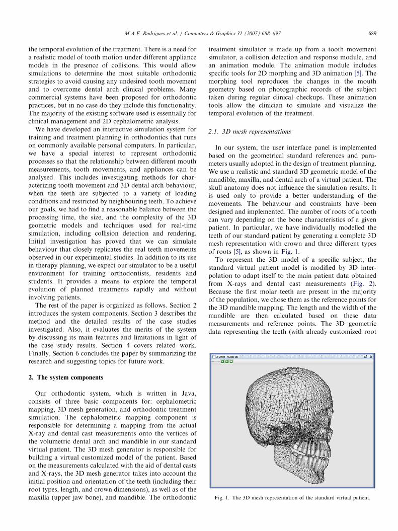
In our system, the user interface panel is implementedbased on the geometrical standard references and para-meters usually adopted in the design of treatment planning.We use a realistic and standard 3D geometric model of themandible, maxilla, and dental arch of a virtual patient. Theskull anatomy does not influence the simulation results. Itis used only to provide a better understanding of themovements. The behaviour and constraints have beendesigned and implemented. The number of roots of a toothcan vary depending on the bone characteristics of a givenpatient. In particular, we have individually modelled theteeth of our standard patient by generating a complete 3Dmesh representation with crown and three different typesof roots [5], as shown in Fig. 1.To represent the 3D model of a specific subject, the
standard virtual patient model is modified by 3D inter-polation to adapt itself to the main patient data obtainedfrom X-rays and dental cast measurements (Fig. 2).Because the first molar teeth are present in the majorityof the population, we chose them as the reference points forthe 3D mandible mapping. The length and the width of themandible are then calculated based on these datameasurements and reference points. The 3D geometricdata representing the teeth (with already customized root
ARTICLE IN PRESS
Fig. 2. 3D meshes representing the mandible and teeth in the system.
length and crown size dimensions) are then uniformlydistributed and positioned across the dental arch, accord-ing to their initial orientations. A tooth absence in thedental arch (if there is any) is represented in our system, byremoving a given tooth (through the user interfacepanel), after generating the customized 3D mesh of apatient. The tooth movements and dental arch can bevisualized from any point of view chosen from the userinterface panel.
The generated mesh representations are composed of asufficient number of vertices and polygons to construct arealistic virtual patient with good degree of accuracy.Approximately 125 vertices (180 polygons) are used tomodel each tooth to represent its skeletal shape. The skullis composed of 3087 vertices (5426 polygons) and the jawof 1094 points (2054 polygons). The quality of allgeometric meshes generated was kept at a very high level,where neither geometric mesh distortions nor mesh non-linearities were found. We designed and implemented twotypes of orthodontic appliance models. First, attached toeach tooth crown at right angles, we designed the bracket,represented by a cube element. The brackets are thenlinked together by an orthodontic wire (with rectangular orspherical shape). Spherical wires are used in our simulatorto rotate the tooth in the x and z-directions, whilerectangular wires are used to translate the tooth in the x,y, and z-directions, as well as to rotate it. Finally, we usedcubic spline curves (whose controls points are the brackets)to generate the appliance models.
2.2. Tooth movement simulator
The system simulates 3D tooth movements through timewith respect to a fixed Cartesian frame located in themiddle of the dental arch. It is designed and implementedto displace and rotate the teeth interactively to obtain thecorrect dental occlusion, based on the measurements andsystem of forces defined by the user in the interface panel.Any tooth (or a group of teeth) can be interactively‘‘extracted’’ or selected through the user interface panel toapply loadings. Using the current and next tooth positionin the dental arch, as well as the force system set up by theuser, our system automatically calculates those new toothpositions (trajectories) that best fit the geometry of the
virtual patient dental arch through linear interpolations,during the evolution of the orthodontic treatment. Eachtooth has its own system of coordinates. A director vectorbetween two neighbouring teeth in the x direction can befound easily. In our simulator, a tooth can be alsodisplaced (translated) into extraction spaces, followingthe direction of the dental arch, by calculating the directorvector. For the z direction, the orthogonal vector iscalculated via the cross product. This is useful, forexample, when the user wants to perform inclinations onthe incisors of the patient.The simplest orthodontic movements [6], such as tipping,
occur about the centre of tooth resistance (13from the root
apex). Translations are modelled in our simulator byapplying a bodily movement where the whole toothstructure is uniformly loaded. It is expected that duringrotations, tipping also may occur. Extrusions and intru-sions are both modelled by vertical movements whereforces are used to move the tooth down or up, respectively.The centre of resistance and centre of rotation of the toothare calculated automatically and they help to evaluate theeffect of the force system on the tooth movement. Thetranslation, inclination, rotation, torque, extrusion, andintrusion tooth movements have all been implemented inour system. They are shown in Table 1.Collision detection is fundamental to interactive simula-
tion systems and ensures that the properties of the solidreal world are maintained. Therefore, we have alsoimplemented collision effects among dental surfaces causedby tooth movements. The computer simulation imposesseveral restrictions that have a direct impact on ourcollision detection method. These include how manyobjects there are in a given orthodontic scenario, theirrelative sizes, level of detail, and positions, if and how theymove, and whether they are rigid or not. The problem ofdetecting when teeth collide, modelling the contact betweenthem and determining an appropriate response, are allcritical operations requiring careful coding to achieve ahigh and constant frame rate. The whole process has tooperate under strict time and size restrictions to guaranteethe correct real-time teeth collisions [7]. Given the usualtime and space trade-off, the detection accuracy must bebalanced against computation time to meet performancerequirements. In addition to an efficient collision method,
we have also implemented a ‘‘domino’’ collision effectamong teeth. After collisions have been detected and thecontact area found, a response must be determined. Thisinvolves an instantaneous direct correction of the directionand speed of movement.
The main characteristics of our pseudo-code used tomove the teeth interactively in presence of collisions ispresented in Algorithm 1, and is detailed as follows. Ineach frame of the simulation, we verify whether there issome force being applied to any tooth (the original user-defined force or the one that was propagated along thedental arch due to collisions). In the affirmative case,Algorithm 1 is called. We first verify the orientation ofapplied force (line 1). Based on the displacement orienta-tion found and current tooth position, we identify the‘‘next tooth’’ (visible or not) in the dental arch (lines 2–4).Following the orientation of the tooth displacement, wethen search for the nearest visible tooth in the dental arch(lines 5–7). The direction vector (line 8) is obtained fromthe centre of mass of a tooth (which is being subjected to aforce) towards the centre of mass of the ‘‘next tooth’’ in thedental arch.
While not detected a collision between the boundingspheres of the moving tooth and the next visible tooth (line9), the moving tooth can still be translated and/or rotated,and the orthodontic wire model used is identified (lines 10and 15). If we change the orthodontic arch model used, thebehaviour of the tooth changes accordingly and this fact istaken into account in our tooth movement simulator.Therefore, if it is necessary to apply a torque, therectangular wire model should be used and the toothrotates with the centre of rotation in this case located at itscrown (lines 10–12). However, if the wire model isrectangular and the tooth is subjected to a force, thistooth can translate in the x, y, and z-directions (lines 10,13, and 14). Finally, if the wire model is spherical and thetooth is subjected to a force, it can only rotate (lines 15 and16). The centre of rotation, in this case, is taken to be aposition located at 1
3of its root length.
In the negative case, the moving tooth stops and theforce being applied to it is partially propagated to thenext visible tooth (that suffered the collision), by simula-ting a ‘‘domino’’ collision effect among teeth (lines 17
and 18) and thus successively, while there is enough forceto move any tooth as well as colliding teeth in thatdirection.
Algorithm 1. The pseudo-code used to move the teeth
interactively in presence of collisions
// nextVisibleTooth is used to collision detection
// nextTooth is used to calculate the direction vector
// Verify the force orientation
01:
if (force o 0) inc ¼ +1; elseif inc ¼ �1; // Get the next tooth instance
elseif // In case of collision, apply force loss to simulate a
domino collision effect
18:
ApplyForce(force*LOSS, nextVisibleTooth);
ARTICLE IN PRESSM.A.F. Rodrigues et al. / Computers & Graphics 31 (2007) 688–697692
3. Case studies and results
In a validation study we investigated a group of patientswith malocclusion problems. On the basis of the ortho-dontist’s clinical experience, we selected four subjects fromthis group on the basis that their clinical problemsrepresent the most common problems in orthodontics.The initial dental casts and cephalometric measurementsthat we used are displayed in Fig. 3 and in Table 2 (lines 2and 3), respectively. As part of the therapy (Fig. 4 and line1 in Table 2), measurements of dental displacements weretaken during clinical checkups of the patients over one
Fig. 3. Dental casts of the four subject
Table 2
Measurements and simulated results for the case studies
for applied forces of (0.02, 0.08, 0.15N) 1; 72; 36
Fig. 4. Therapy planning for patient 1 (a and b),
year. The reference teeth on the cast models, and thepositions to which the teeth moved, were marked foridentification. We used the molar and premolar teeth as thereference teeth in our computer simulations.In planning the biomechanical aspects of orthodontic
treatment for a specific patient, it is imperative that theorthodontist consider not only the forces required for thenecessary tooth movement to achieve the objectives of thetreatment, but also any undesired tooth movement thatmay occur in response to these forces. What happens usingour simulation system depends on the level and duration offorce.
s. Frontal (a) and lateral (b) views.
Patient 2 Patient 3 Patient 4
Inclination of Filling the space Filling the space
ARTICLE IN PRESSM.A.F. Rodrigues et al. / Computers & Graphics 31 (2007) 688–697 693
We classified the applied loadings used in our study aslow, medium, and high force values (0.02, 0.08, and 0.15N,respectively). Different effects of loading acting on theappliance (tooth) are then observed and behaviours aresimulated. Our system calculates, in number of frames, thetime interval needed for a certain tooth to reach the desiredposition in the dental arch. All the data generated by ourcomputer simulations were evaluated by comparing thecalculated and clinically observed tooth movements. At thestart of our computer simulations, customized virtualpatient models were generated. We used our standardvirtual patient (Fig. 1) as the basis for all of the simulatedcase studies. We customized the shape of the standardmodel using medical measurements and advice fromorthodontic experts. The 3D results that were obtainedfor each customized subject are shown in Fig. 5.
The treatment that was designed for the first patientrequired the extraction of the first premolars on both sidesof the mandible and maxilla (Fig. 4a). This was followed bythe use of a fixed appliance model with brackets linked by arectangular wire with pre-established torsion in its struc-ture. The intention is that the canines have to be distalizedinto the extraction space (approximately 6.8mm) indirection of the molars, and the incisor group retractedand their angle of inclination corrected (Fig. 4b). Thesecond subject (Figs. 3 and 5) had the problem that theupper incisors projected forwards in the maxilla with anextrusion of 8.04mm. There were only 23 teeth on hisdental arch (12 teeth in the mandible, and 11 in themaxilla). The treatment plan involved retraction of hisupper incisors (Fig. 4c). Patient 3 (Figs. 3 and 5) had adental arch with 30 teeth (14 teeth in the mandible, and 16in the maxilla), with a 3.0mm space between his upperincisors teeth. In addition to this problem, the upper
Fig. 5. Initial 3D geometric configurations of the four simulate
incisors had an inclination of 31.511, with an extrusion of9.41mm. For this patient the treatment plan, shown inFig. 4d, involved closing the gap between the incisors.Finally, patient 4 (Figs. 3 and 5) had 28 teeth on his dentalarch (14 teeth on the maxilla and 14 teeth on the mandible),with a space of 4.0mm between the first premolar and thecanine positioned on the right-hand side of the mandible.The treatment plan is shown in Fig. 4e.The numerical and graphical results of the computer
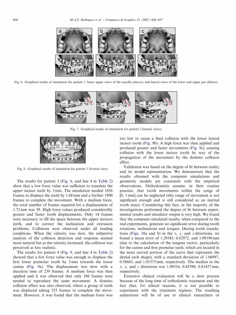
simulations for all patients are summarized in Table 2(line 4), and in Figs. 6, 7, 8 and 9, respectively. The resultsshowed that a low force (0.02N) was not sufficient todisplace the canines of the patient 1 (Fig. 6a). A mediumforce (0.08N) needed 72 frames to move the canines by6.8mm, when collision detection was found with thesecond premolar tooth (Fig. 6b). The application of a highforce value (0.15N) needed only 36 frames to move thecanines to the planned position. Similarly to whathappened with the medium force, the teeth stopped movingwhen a collision was detected (Fig. 6c).The results for patient 2 (Fig. 7, and line 4 in Table 2)
show that a low force value was not enough to change theincline of the upper central incisors (Fig. 7a). A mediumforce produced a very slow movement and needed 106frames to produce an inclination of 8.041. This result wasvery close to our empirical studies, and is shown in Fig. 7b.The application of a high force value produced a relativelyfast movement and needed just 50 frames to achieve aninclination of 8.161 (Fig. 7c). Collisions among teethwere not detected. Medium force values were moreappropriate, because of the high risk of causing anundesired tooth movement, for example where the upperincisors might incline beyond the angle aestheticallyconsidered as ideal.
d patients. Frontal views (above) and lateral views (below).
ARTICLE IN PRESS
Fig. 7. Graphical results of simulation for patient 2 (lateral views).
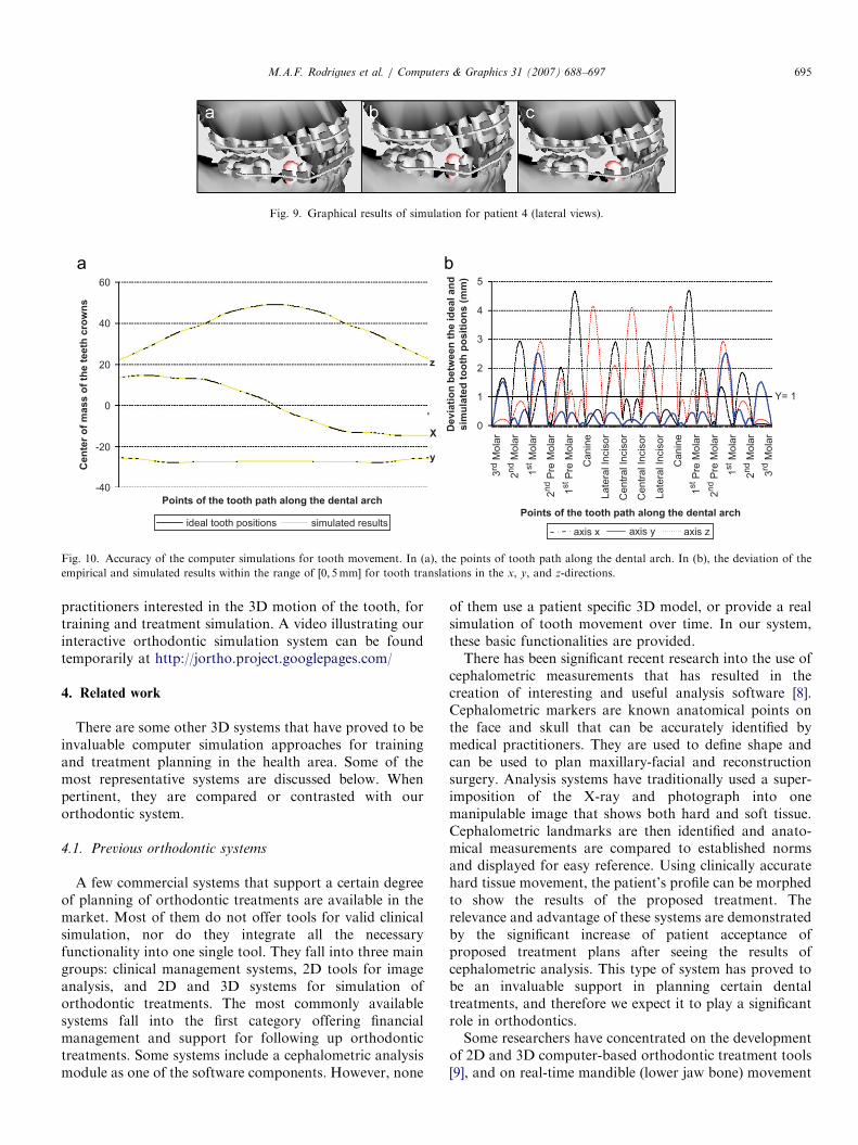
Fig. 8. Graphical results of simulation for patient 3 (frontal view).
Fig. 6. Graphical results of simulation for patient 1. Inner upper views of the maxilla (above), and lateral views of the lower and upper jaw (below).
The results for patient 3 (Fig. 8, and line 4 in Table 2)show that a low force value was sufficient to translate theupper incisor teeth by 3mm. The simulation needed 1856frames to displace the teeth by 1.68mm and a further 1890frames to complete the movement. With a medium force,the total number of frames required for a displacement of1.72mm was 39. High force values produced considerablygreater and faster tooth displacements. Only 14 frameswere necessary to fill the space between the upper incisorsteeth, and to correct the inclination and extrusionproblems. Collisions were observed under all loadingconditions. When the velocity was slow, the subjectiveanalysis of the collision detection and response seemedmore natural but as the velocity increased, the collision wasperceived as less realistic.
The results for patient 4 (Fig. 9, and line 4 in Table 2)showed that a low force value was enough to displace thefirst lower premolar tooth by 3mm towards the lowercanine (Fig. 9a). The displacement was slow with aduration time of 239 frames. A medium force was thenapplied and it was observed that only 108 frames wereneeded to reproduce the same movement. A dominocollision effect was also observed, where a group of teethwas displaced taking 253 frames to complete the move-ment. However, it was found that the medium force was
too low to cause a final collision with the lower lateralincisor tooth (Fig. 9b). A high force was then applied andproduced greater and faster movements (Fig. 9c), causingcollision with the lower incisor tooth by way of thepropagation of the movement by the domino collisioneffect.Validation was based on the degree of fit between reality
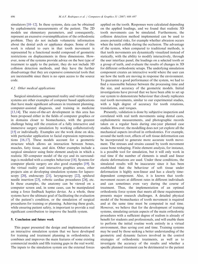
and its model representation. We demonstrate that theresults obtained with the computer simulations andgeometric models are consistent with the empiricalobservations. Orthodontists assume, in their routinepractice, that tooth movements within the range of[0, 1mm] can be neglected (this range of movement is notsignificant enough and is still considered as an inertialtooth state). Considering this fact, in the majority of theinvestigations performed the degree of fit between experi-mental results and simulator output is very high. We foundthat the computer simulated results, when compared to thereal experiments, generate no significant error during toothrotations, inclinations and torques. During tooth transla-tions (Figs. 10a and b) in the x, y, and z-directions, wefound a mean error of 1.29343, 0.62972, and 1.09198mm(due to the calculation of the tangent vector, particularlyfor the canine and first premolar teeth, which are located inthe most curved portion of the curve that represents thedental arch shape), with a standard deviation of 1.06997,0.58663, and 1.01575mm, respectively. The median in thex, y, and z directions was 1.08516, 0.42390, 0.81437mm,respectively.Extensive clinical evaluation will be a slow process
because of the long time of orthodontic treatment and thefact that, for ethical reasons, it is not possible toexperiment with the treatment regimes. The resultinganimations will be of use to clinical researchers or
ARTICLE IN PRESS
De
via
tio
n b
etw
ee
n t
he
id
ea
l a
nd
sim
ula
ted
to
oth
po
sit
ion
s (
mm
)
Points of the tooth path along the dental arch
Ce
nte
r o
f m
as
s o
f th
e t
ee
th c
row
ns
Points of the tooth path along the dental arch
60
40
20
0
-20
-40
z
X
y
Y= 1
3rd
Mo
lar
2nd M
ola
r
1st M
ola
r
2nd P
re M
ola
r
1st P
re M
ola
r
Ca
nin
e
La
tera
l In
cis
or
Ce
ntr
al In
cis
or
Ce
ntr
al In
cis
or
La
tera
l In
cis
or
Ca
nin
e
1st P
re M
ola
r
2nd P
re M
ola
r
1st M
ola
r
2nd M
ola
r
3rd
Mo
lar
5
4
3
2
1
0
axis x axis y axis zsimulated resultsideal tooth positions
Fig. 10. Accuracy of the computer simulations for tooth movement. In (a), the points of tooth path along the dental arch. In (b), the deviation of the
empirical and simulated results within the range of ½0; 5mm� for tooth translations in the x, y, and z-directions.
Fig. 9. Graphical results of simulation for patient 4 (lateral views).
practitioners interested in the 3D motion of the tooth, fortraining and treatment simulation. A video illustrating ourinteractive orthodontic simulation system can be foundtemporarily at http://jortho.project.googlepages.com/
4. Related work
There are some other 3D systems that have proved to beinvaluable computer simulation approaches for trainingand treatment planning in the health area. Some of themost representative systems are discussed below. Whenpertinent, they are compared or contrasted with ourorthodontic system.
4.1. Previous orthodontic systems
A few commercial systems that support a certain degreeof planning of orthodontic treatments are available in themarket. Most of them do not offer tools for valid clinicalsimulation, nor do they integrate all the necessaryfunctionality into one single tool. They fall into three maingroups: clinical management systems, 2D tools for imageanalysis, and 2D and 3D systems for simulation oforthodontic treatments. The most commonly availablesystems fall into the first category offering financialmanagement and support for following up orthodontictreatments. Some systems include a cephalometric analysismodule as one of the software components. However, none
of them use a patient specific 3D model, or provide a realsimulation of tooth movement over time. In our system,these basic functionalities are provided.There has been significant recent research into the use of
cephalometric measurements that has resulted in thecreation of interesting and useful analysis software [8].Cephalometric markers are known anatomical points onthe face and skull that can be accurately identified bymedical practitioners. They are used to define shape andcan be used to plan maxillary-facial and reconstructionsurgery. Analysis systems have traditionally used a super-imposition of the X-ray and photograph into onemanipulable image that shows both hard and soft tissue.Cephalometric landmarks are then identified and anato-mical measurements are compared to established normsand displayed for easy reference. Using clinically accuratehard tissue movement, the patient’s profile can be morphedto show the results of the proposed treatment. Therelevance and advantage of these systems are demonstratedby the significant increase of patient acceptance ofproposed treatment plans after seeing the results ofcephalometric analysis. This type of system has proved tobe an invaluable support in planning certain dentaltreatments, and therefore we expect it to play a significantrole in orthodontics.Some researchers have concentrated on the development
of 2D and 3D computer-based orthodontic treatment tools[9], and on real-time mandible (lower jaw bone) movement
ARTICLE IN PRESSM.A.F. Rodrigues et al. / Computers & Graphics 31 (2007) 688–697696
simulators [10–12]. In these systems, data can be obtainedby cephalometric measurements of the patient. The 2Dmodels use elementary parameters, and consequently,represent an excessive oversimplification of the orthodonticproblem. They do not include volumetric informationabout the dental arch or appliance shapes. Some of thiswork is related to ours in that tooth movement isrepresented by a functional model composed of geometricrestrictions on displacements in three dimensions. How-ever, none of the systems provide advice on the best type oftreatment to apply to the patient, they do not include 3Dcollision detection methods, and they have the furtherdisadvantage that they are expensive commercial tools thatare inextensible since there is no open access to the sourcecode.
4.2. Other medical applications
Surgical simulation, augmented reality and virtual realitysystems are other examples of computer based applicationsthat have made significant advances in treatment planning,computer-assisted diagnosis, and training in medicine[13,14]. The state-of-the-art development in this area hasbeen proposed either in the fields of computer graphics orin domains closer to biomechanics, with the greatestchallenge being still the creation of a fully interactive andimmersive surgery simulation by working collaboratively[15] or individually. Examples are the work done on skin,with particular application to facial expression representa-tions [16,17]. These models account for a geometricstructure which allows an interaction between bones,muscles, fatty tissue, and skin. Other examples include asurgical simulator using finite element analysis in which arealistic 3D computer model of the eye and its surround-ings is modelled with a complex behaviour [18]. Systems forcomputer plastic surgery are also good examples [19]. Inthe virtual reality and interactive graphics areas, otherprojects aim at developing simulation systems for laparo-scopy [20], endoscopy [21], laryngoscopy [22], epiduralneedle insertion [23], robotic cardiac procedures [24], etc.In these examples, the anatomy can be viewed on acomputer screen and, in some cases, can be manipulatedusing a force feedback haptics device. As a whole, thesesystems have the ultimate goal of facilitating the evaluationof the patient’s condition, or the simulation of surgicalprocedures for training or planning. Achieving these goals,while ensuring patient safety, is important to provide a realsignificant contribution to improve the health system.
5. Conclusion and future work
This paper presented the design and implementation ofan interactive simulation system that we have developedfor training and treatment planning in orthodontics. Itcombines and improves the main features of some existingcommercial models and fills training gaps in the real world.The inputs to the simulation system are the external forces
applied on the tooth. Responses were calculated dependingon the applied loadings, and we found that realistic 3Dtooth movements can be simulated. Furthermore, thecollision detection method implemented can be used toassess potential risks, for example whether abrasion occurswhen the teeth collide during the occlusion. The advantageof the system, when compared to traditional methods, isthat teeth movements are dynamically visualized instead ofstatically, with the ability to modify interactively, throughthe user interface panel, the loadings on a selected tooth ora group of teeth, and evaluate the results of changes in 3Dfor different orthodontic setups. The underlying simulationcomponent creates an interactive world where the user cansee how the teeth are moving in response the environment.To guarantee a good performance of the system, we had tofind a reasonable balance between the processing time andthe size, and accuracy of the geometric models. Initialinvestigations have proved that we have been able to set upour system to demonstrate behaviour that closely replicatesreal tooth movements, similar to our experimental studies,with a high degree of accuracy for tooth rotations,translations, and torques.Presently, validation is done by subjective inspection and
correlated with real teeth movements using dental casts,cephalometric measurements, and photographic recordstaken on a regular basis during one-year planned casestudies. However, the modelling does not yet explore all themechanical aspects involved in orthodontics. For example,around the teeth root, effects of soft tissue deformation canbe incorporated to generate more accurate tooth move-ment. The stresses and strains caused by tooth movementcause bone reshaping. Finite element analysis, for instance,is a possible tool for simulation, but it will only work inreal time if the number of elements is small and linearelastic deformations are used. Under these conditions, thesimulated results will be inaccurate since it has beenestablished that the behaviour of soft tissue underdeformation is highly non-linear and has a clearly time-dependent component. Also, it is known that tooth-movement occurs at different rates in different individualsand can sometimes even vary during the course oftreatment. Thus, the implementation of an optimalorthodontic force system that meets all these requirementspresents major research challenges. A detailed physicalmodel of the biomechanics of tooth movement is requiredand at the same time must be computed in real time.However, we believe that for the development of trainingsystems, simulating certain aspects of the main orthodonticprocedures with a sufficient degree of realism is already ofbenefit for students and professionals, and will enable themto perform the initial routine work entirely in a virtualenvironment, thus saving cost and time. Training systemsmay be used by those seeking a better understanding of thegeometric and dynamic factors involved in the controlstrategies of orthodontic treatments, as well as toinvestigate the accuracy of the results and whether aspecific planned treatment can be detrimental to the patient
ARTICLE IN PRESSM.A.F. Rodrigues et al. / Computers & Graphics 31 (2007) 688–697 697
in any circumstance. We hope that this work will providethe basis for the development of a practical but effectivegraphical, clinical tool for research purposes in orthodon-tics.
It is becoming increasingly evident that the medicaldomain can offer many opportunities for the application ofinteractive computer graphics. However, the one aspectthat may require a further horizon is the development ofhigh-fidelity patient models for design, testing, andvalidation [25]. Therefore, the next stage of this work isto evolve the current implementation to improve thegeometric and modelling accuracy. Among the researchto be performed we plan to use 3D reconstruction methodsto replace the manual dental plaster measurements. Dentalcasts can be scanned three-dimensionally and their volumedetermined exactly from the data set. This will improve thegeometric accuracy of the 3D meshes. Use could be madeof statistical shape models of the mandible, maxilla, andteeth to improve the speed and accuracy with which thestandard geometric model can be made patient specific. Wehave previously constructed a statistical shape model of themandible in a different application that demonstrated thatpatient specific reconstruction can be achieved using asmall number of simple cephalometric measurements [26].Lastly, we hope to explore the use of tactile feedback forthe manipulation of objects.
Acknowledgements
The research was partly supported by The NationalCouncil for Scientific and Technological Development ofBrazil (CNPq) under grant No. 303046/2006-6.
References
[1] Alcaniz M, Montserrat C, Grau V, Chinesta F, Ramon A, Albalat S.
An advanced system for the simulation and planning of orthodontic
treatment. Medical Image Analysis 1998;2(1):61–79.
[2] Bisler A, Bockholt U, Voss G. The virtual articulator-applying VR
technologies to dentistry. In: Proceedings of the 6th IEEE interna-
tional conference on informatics and visualisation; 2002. p. 600–2.
[3] Ferrario VF, Sforza C, Schmitz JH, Miani A, Serrao GA. 3D
computerized mesh diagram analysis and its application in soft tissue
facial morphometry. American Journal of Orthodontic and Dento-
facial Orthopedics 1998;114:404–13.
[4] Soncini M, Pietrabissa R. Quantitative approach for the prediction of
tooth movement during orthodontic treatment. Computer Methods
Biomechanics and Biomedical Engineering 2002;5(5):361–8.