Page 1
AN INTERNAL PROJECT ONAN INTERNAL PROJECT ONAN INTERNAL PROJECT ONAN INTERNAL PROJECT ON
Lubricating Oils Blending, Filling and PackingLubricating Oils Blending, Filling and PackingLubricating Oils Blending, Filling and PackingLubricating Oils Blending, Filling and Packing
at Indian Oil Corporation Ltdat Indian Oil Corporation Ltdat Indian Oil Corporation Ltdat Indian Oil Corporation Ltd
Lube Blending Plant,Lube Blending Plant,Lube Blending Plant,Lube Blending Plant,
THE POTENITAL USE OF THE POTENITAL USE OF THE POTENITAL USE OF THE POTENITAL USE OF
AN INTERNAL PROJECT ONAN INTERNAL PROJECT ONAN INTERNAL PROJECT ONAN INTERNAL PROJECT ON
Lubricating Oils Blending, Filling and PackingLubricating Oils Blending, Filling and PackingLubricating Oils Blending, Filling and PackingLubricating Oils Blending, Filling and Packing
at Indian Oil Corporation Ltdat Indian Oil Corporation Ltdat Indian Oil Corporation Ltdat Indian Oil Corporation Ltd
Lube Blending Plant,Lube Blending Plant,Lube Blending Plant,Lube Blending Plant, Budge BudgeBudge BudgeBudge BudgeBudge Budge
&&&&
THE POTENITAL USE OF THE POTENITAL USE OF THE POTENITAL USE OF THE POTENITAL USE OF BIOLUBRICANTS IN THE BIOLUBRICANTS IN THE BIOLUBRICANTS IN THE BIOLUBRICANTS IN THE
INDUSTRYINDUSTRYINDUSTRYINDUSTRY
Manidipa Pandey
Third Year Undergraduate Student
Department of Chemical Engineering
1
1
Lubricating Oils Blending, Filling and PackingLubricating Oils Blending, Filling and PackingLubricating Oils Blending, Filling and PackingLubricating Oils Blending, Filling and Packing
Budge BudgeBudge BudgeBudge BudgeBudge Budge
BIOLUBRICANTS IN THE BIOLUBRICANTS IN THE BIOLUBRICANTS IN THE BIOLUBRICANTS IN THE
Submitted by
Manidipa Pandey
Third Year Undergraduate Student
Department of Chemical Engineering
IIT Kharagpur
Page 2
2
2
ACKNOWLEDGEMENTACKNOWLEDGEMENTACKNOWLEDGEMENTACKNOWLEDGEMENT
It’s a great pleasure to express my gratitude to Professor Shirshendu De, Head of the Dept. Chemical
Engineering, IIT Kharagpur for recommending me for internal project at IOCL, major National Oil
Company of the country & Ms. Maria Bhattacharya, General Manager (L&D) ER, IOCL for referring me to
Lube Blending Plant, Budge Budge to execute this project. This project has given me an excellent
overview of lubricants manufacturing process and marketing.
I would like to convey my regards to Sri Anup Kumar Das, DGM (Plant) LBP Budge Budge for providing
me with this great opportunity to learn about this plant & execute this interesting project.
My sincere regards and gratitude to my project guide Dr. B. Anand, AM (LQC), for his endeavor, constant
inspiration and guidance to impart knowledge on the subject and execute the valuable project
successfully within a short time.
I would like to extend my sincere gratitude to my Mr.Arup Kumar Das, Chief Manager (LQC), Mr.Arun
Kanti Bala, Chief Manager (LQC), Mr. Gautam Rajak, Sr. Manager (LQC), Mr. Santosh Kumar,
Operations Officer, Ms. Shubhasri Hore (Operations Officer), Sri Babu Lal, (Operations Officer), and Sri
Nimit Agrawal, (Operations Officer) for their constant inspiration, guidance & support under whose
tutelage I was successful in executing this project.
Page 3
3
3
CONTENTS:
SERIALSERIALSERIALSERIAL TOPICTOPICTOPICTOPIC PAGEPAGEPAGEPAGE
1 IOCL- AN INTRODUCTION 4
2 A LUBE BLENDING PLANT,BUDGE BUDGE- ABOUT THE PLANT 5
2 B LUBRICANTS – TYPES, Introduction 6
3 A LUBE – FUNCTIONS, COMPOSITION 7
3 B BASE OIL 7
3 C ADDITIVES 8-9
4 MAJOR FACILITIES AND INFRASTRUCTURE 9-10
5 ELECTRICAL EQUIPMENT 10-11
6 AIR COMPRESSOR 11-12
7 BOILER 12
8 LUBE BLENDING 13-14
9 QUALITY CONTROL 15
A EQUIPMENTS USED IN THE QUALITY TESTING LAB,PROCESS AND SIGNIFICANCE 15-21
B TEST FOR PACKAGING MATERIAL 21
9 STORAGE AND DISPATCH 22-23
10 MAJOR CUSTOMERS IN AND ABROAD 24-25
11 MISCELLANEOUS FACILITIES,,,, SAFETY 25-27
12 LAB SCALE BLENDING AND TESTING 27-30
13 Biolubricants: Raw materials, chemical modifications and environmental
benefits
30-32
14 CONCLUSION 32
15 BIBLIOGRAPHY 33
Page 4
4
4
INDIAN OIL CORPORATION LIMITEDINDIAN OIL CORPORATION LIMITEDINDIAN OIL CORPORATION LIMITEDINDIAN OIL CORPORATION LIMITED
INTRODUCTIONINTRODUCTIONINTRODUCTIONINTRODUCTION
Indian Oil Corporation Limited was established in 1959. It mushroomed itself into The INDIAN OIL
CORPORATION in 1964, collaborating with the Indian Refineries Ltd. It covers various operations under
its wings like Pipelines, Refineries Marketing, Petrochemicals, etc. which has helped it to establish its
roots stringently to its empowerment and growth in this frontier. With over 1000 commercial grades
and over 1,500 formulations developed by our in-house R&D Centre, SERVO serves as a one-stop shop
for complete lubrication solutions in the automotive, industrial and marine segments.
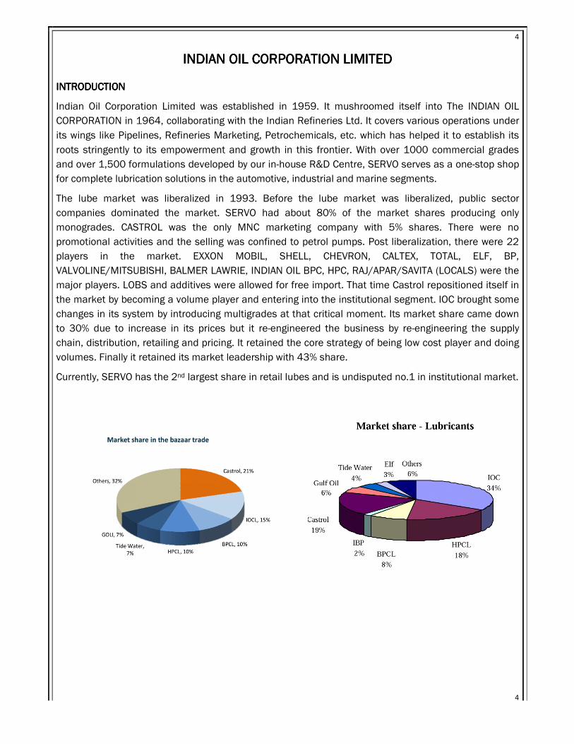
The lube market was liberalized in 1993. Before the lube market was liberalized, public sector
companies dominated the market. SERVO had about 80% of the market shares producing only
monogrades. CASTROL was the only MNC marketing company with 5% shares. There were no
promotional activities and the selling was confined to petrol pumps. Post liberalization, there were 22
players in the market. EXXON MOBIL, SHELL, CHEVRON, CALTEX, TOTAL, ELF, BP,
VALVOLINE/MITSUBISHI, BALMER LAWRIE, INDIAN OIL BPC, HPC, RAJ/APAR/SAVITA (LOCALS) were the
major players. LOBS and additives were allowed for free import. That time Castrol repositioned itself in
the market by becoming a volume player and entering into the institutional segment. IOC brought some
changes in its system by introducing multigrades at that critical moment. Its market share came down
to 30% due to increase in its prices but it re-engineered the business by re-engineering the supply
chain, distribution, retailing and pricing. It retained the core strategy of being low cost player and doing
volumes. Finally it retained its market leadership with 43% share.
Currently, SERVO has the 2nd largest share in retail lubes and is undisputed no.1 in institutional market.
Page 5
5
5
LUBE BLENDING PLANT, BUDGE BUDGELUBE BLENDING PLANT, BUDGE BUDGELUBE BLENDING PLANT, BUDGE BUDGELUBE BLENDING PLANT, BUDGE BUDGE
HISTORY
The Budge Budge Lube Blending Plant started in September 1989 and belonged to Caltex. Then it was
taken over by IBP Corporation Limited. IBP Corporation limited was found in the name of Indo Burma
Petroleum Corporation Limited in 1909 and in 1983 the company’s changed to IBP Corporation
Limited. On 2nd June 2007, IBP merged with IOC and this plant became a part of IOCL‘s lube blending
plant.
LBP Budge Budge has a blending capacity of 35000MT/PA in single shift and produces mainly
industrial and automotive grades of lubricants. The plant has an ISO 9001-2015, 14001:2015 and
ISO/TS 16949: 2009 certification.
PLANT LOCATION
The Lube Blending Plant, known as LBP Budge Budge, is located at Budge Budge which is an important
port and industrial location for oil and jute located on the eastern bank of river HOOGLY, 22 kms off
Kolkata. This plant lies under the administrative jurisdiction of 24 PGS(S). It gets refined oil from Haldia
refinery, 60 nautical miles away.
PLANT AREA
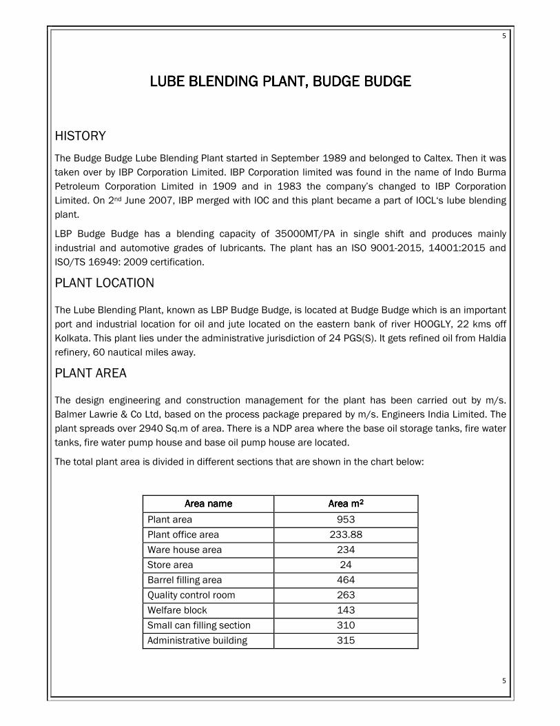
The design engineering and construction management for the plant has been carried out by m/s.
Balmer Lawrie & Co Ltd, based on the process package prepared by m/s. Engineers India Limited. The
plant spreads over 2940 Sq.m of area. There is a NDP area where the base oil storage tanks, fire water
tanks, fire water pump house and base oil pump house are located.
The total plant area is divided in different sections that are shown in the chart below:
Area nameArea nameArea nameArea name Area mArea mArea mArea m2222
Plant area 953
Plant office area 233.88
Ware house area 234
Store area 24
Barrel filling area 464
Quality control room 263
Welfare block 143
Small can filling section 310
Administrative building 315
Page 6
6
6
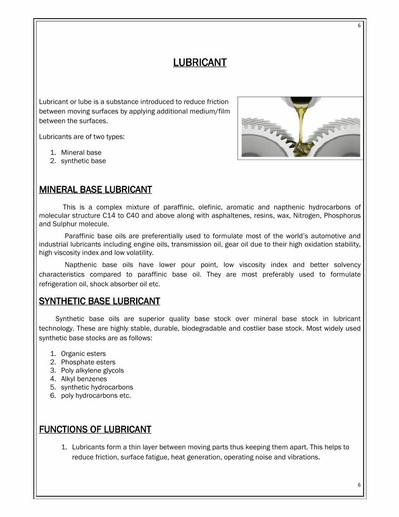
LUBRICANTLUBRICANTLUBRICANTLUBRICANT
Lubricant or lube is a substance introduced to reduce friction
between moving surfaces by applying additional medium/film
between the surfaces.
Lubricants are of two types:
1. Mineral base 2. synthetic base
MINERAL BASE LUBRICANTMINERAL BASE LUBRICANTMINERAL BASE LUBRICANTMINERAL BASE LUBRICANT
This is a complex mixture of paraffinic, olefinic, aromatic and napthenic hydrocarbons of molecular structure C14 to C40 and above along with asphaltenes, resins, wax, Nitrogen, Phosphorus and Sulphur molecule.
Paraffinic base oils are preferentially used to formulate most of the world’s automotive and industrial lubricants including engine oils, transmission oil, gear oil due to their high oxidation stability, high viscosity index and low volatility.
Napthenic base oils have lower pour point, low viscosity index and better solvency
characteristics compared to paraffinic base oil. They are most preferably used to formulate
refrigeration oil, shock absorber oil etc.
SYNTHETIC BASE LUBRICANTSYNTHETIC BASE LUBRICANTSYNTHETIC BASE LUBRICANTSYNTHETIC BASE LUBRICANT
Synthetic base oils are superior quality base stock over mineral base stock in lubricant
technology. These are highly stable, durable, biodegradable and costlier base stock. Most widely used
synthetic base stocks are as follows:
1. Organic esters 2. Phosphate esters 3. Poly alkylene glycols 4. Alkyl benzenes 5. synthetic hydrocarbons 6. poly hydrocarbons etc.
FUNCTIONS OF LUBRICANTFUNCTIONS OF LUBRICANTFUNCTIONS OF LUBRICANTFUNCTIONS OF LUBRICANT
1. Lubricants form a thin layer between moving parts thus keeping them apart. This helps to
reduce friction, surface fatigue, heat generation, operating noise and vibrations.
Page 7
7
7
2. Liquid and gaseous lubricants can transfer heat. Liquid lubricants are more effective as they
have high specific heat capacity. Circulation of lubricants helps temperature regulation.
3. Lubricants reduce surface-to-surface friction. The lubricant-to-surface friction is much less
than that and it contains additives known as friction modifiers which help in reducing
friction.
4. The circulation of lubricants helps to carry away the internally generated debris and external
contaminants that get introduced into the system.
5. It prevents wear and tear by keeping the moving parts apart.
6. Lubricants are formulated with additives that form chemical bonds with surfaces or exclude
moisture to prevent corrosion and rust
7. It occupies the clearance between moving parts through capillary force thus sealing the
clearance. This effect is used to seal piston and shafts.
8. It is also used to transmit power by acting as a hydraulic fluid.
BASE OILBASE OILBASE OILBASE OIL
MINERAL BASE OILMINERAL BASE OILMINERAL BASE OILMINERAL BASE OIL- GROUP I, II, III:
This is a complex mixture of paraffinic, olefinic, aromatic and naphthenic hydrocarbons of molecular
structure C14 to C40 and above along with asphaltenes, resins, wax, Nitrogen, Phosphorus and
Sulphur molecule
Paraffinic base oils are preferentially used to formulate most of the world’s automotive and industrial
lubricants including engine oils, transmission oil, gear oil due to their high oxidation stability, high
viscosity index and low volatility.
Naphthenic base oils have lower pour point, low viscosity index and better solvency characteristics
compared to paraffinic base oil. They are most preferably used to formulate refrigeration oil, shock
absorber oil etc.
SYNTHETIC BASE OILSYNTHETIC BASE OILSYNTHETIC BASE OILSYNTHETIC BASE OIL
Synthetic base oils are superior quality base stock over mineral base stock in lubricant technology.
These are highly stable, durable, biodegradable and costlier base stock. Most widely used synthetic
base stocks are organic esters, phosphate esters, poly alkaline glycols, alkyl benzenes, synthetic
hydrocarbons& poly hydrocarbons etc. GROUP IV, V falls under this category.
ADDITIVESADDITIVESADDITIVESADDITIVES
Additives are used to boost performance of lubricants and impart performance characteristics. It is vital
for prolonged use of motor oil in modern internal combustion engines, gear boxes, automatic
transmissions and bearings. Some of the additives used and their functions are given below:
Page 8
8
8
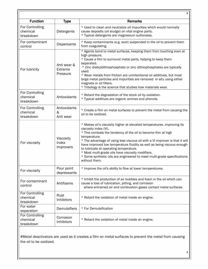
FunctionFunctionFunctionFunction TypeTypeTypeType RemarksRemarksRemarksRemarks
For Controlling chemical breakdown
Detergents * Used to clean and neutralize oil impurities which would normally cause deposits (oil sludge) on vital engine parts. * Typical detergents are magnesium sulfonates.
For contaminant control
Dispersants * Keep contaminants (e.g. soot) suspended in the oil to prevent them from coagulating.
For lubricity Anti wear & Extreme Pressure
* Agents bond to metal surfaces, keeping them from touching even at high pressure. * Cause a film to surround metal parts, helping to keep them separated. * Zinc dialkyldithiophosphate or zinc dithiophosphates are typically used. * Wear metals from friction are unintentional oil additives, but most large metal particles and impurities are removed in situ using either magnets or oil filters. * Tribology is the science that studies how materials wear.
For Controlling chemical breakdown
Antioxidants * Retard the degradation of the stock oil by oxidation. * Typical additives are organic amines and phenols.
For Controlling chemical breakdown
Antioxidants & Anti wear
* Create a film on metal surfaces to prevent the metal from causing the oil to be oxidized.
For viscosity Viscosity Index Improvers
* Makes oil’s viscosity higher at elevated temperatures, improving its viscosity index (VI). * This combats the tendency of the oil to become thin at high temperature. * The advantage of using less viscous oil with a VI improver is that it will have improved low temperature fluidity as well as being viscous enough to lubricate at operating temperature. * Most multi-grade oils have viscosity modifiers. * Some synthetic oils are engineered to meet multi-grade specifications without them.
For viscosity Pour point depressants
* Improve the oil's ability to flow at lower temperatures.
For contaminant control
Antifoams * Inhibit the production of air bubbles and foam in the oil which can cause a loss of lubrication, pitting, and corrosion where entrained air and combustion gases contact metal surfaces.
For Controlling chemical breakdown
Rust Inhibitors
* Retard the oxidation of metal inside an engine.
For water separation
Demulsifiers * For Demulsification
For Controlling chemical breakdown
Corrosion Inhibitors
* Retard the oxidation of metal inside an engine.
#Metal deactivators are used as it creates a film on metal surfaces to prevent the metal from causing
the oil to be oxidized.
Page 9
9
9
# Friction modifiers or friction reducers are used for improving lubricity as it reduces friction between
moving parts it alters the lubricity of the base oil. Whale oil was used historically but now molybdenum
disulphide is used.
# Dyes are sometimes added while blending in amount of about 1L while making selected grades. They
are used for checking leakages. Some dyes are fluorescent and can be seen only under UV light.
MAJOR FACILITIES AND INFRASTRUCTUREMAJOR FACILITIES AND INFRASTRUCTUREMAJOR FACILITIES AND INFRASTRUCTUREMAJOR FACILITIES AND INFRASTRUCTURE
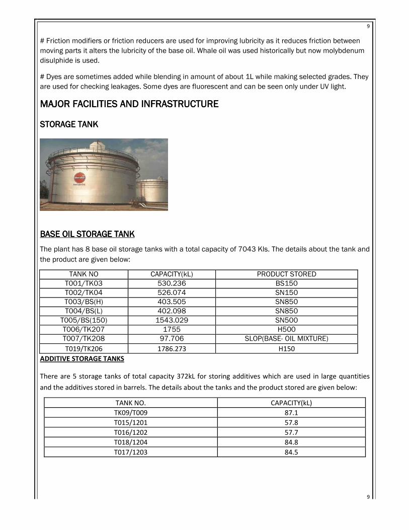
STORAGE TANKSTORAGE TANKSTORAGE TANKSTORAGE TANK
BASE OIL STORAGE TANK BASE OIL STORAGE TANK BASE OIL STORAGE TANK BASE OIL STORAGE TANK
The plant has 8 base oil storage tanks with a total capacity of 7043 Kls. The details about the tank and
the product are given below:
TANK NO CAPACITY(kL) PRODUCT STORED
T001/TK03 530.236 BS150
T002/TK04 526.074 SN150
T003/BS(H) 403.505 SN850
T004/BS(L) 402.098 SN850
T005/BS(150) 1543.029 SN500
T006/TK207 1755 H500
T007/TK208 97.706 SLOP(BASE- OIL MIXTURE)
T019/TK206 1786.273 H150
ADDITIVE STORAGE TANKS
There are 5 storage tanks of total capacity 372kL for storing additives which are used in large quantities
and the additives stored in barrels. The details about the tanks and the product stored are given below:
TANK NO. CAPACITY(kL)
TK09/T009 87.1
T015/1201 57.8
T016/1202 57.7
T018/1204 84.8
T017/1203 84.5
Page 10
10
10
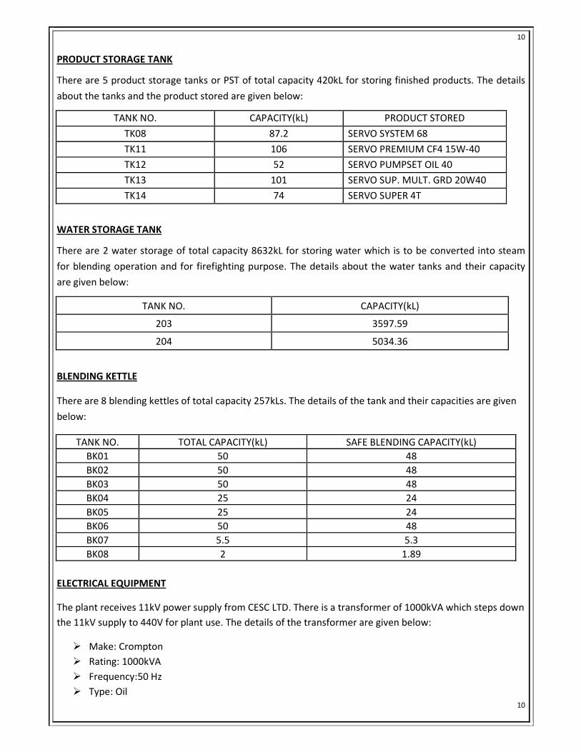
PRODUCT STORAGE TANK
There are 5 product storage tanks or PST of total capacity 420kL for storing finished products. The details
about the tanks and the product stored are given below:
TANK NO. CAPACITY(kL) PRODUCT STORED
TK08 87.2 SERVO SYSTEM 68
TK11 106 SERVO PREMIUM CF4 15W-40
TK12 52 SERVO PUMPSET OIL 40
TK13 101 SERVO SUP. MULT. GRD 20W40
TK14 74 SERVO SUPER 4T
WATER STORAGE TANK
There are 2 water storage of total capacity 8632kL for storing water which is to be converted into steam
for blending operation and for firefighting purpose. The details about the water tanks and their capacity
are given below:
TANK NO. CAPACITY(kL)
203 3597.59
204 5034.36
BLENDING KETTLE
There are 8 blending kettles of total capacity 257kLs. The details of the tank and their capacities are given
below:
TANK NO. TOTAL CAPACITY(kL) SAFE BLENDING CAPACITY(kL)
BK01 50 48
BK02 50 48
BK03 50 48
BK04 25 24
BK05 25 24
BK06 50 48
BK07 5.5 5.3
BK08 2 1.89
ELECTRICAL EQUIPMENT
The plant receives 11kV power supply from CESC LTD. There is a transformer of 1000kVA which steps down
the 11kV supply to 440V for plant use. The details of the transformer are given below:
� Make: Crompton
� Rating: 1000kVA
� Frequency:50 Hz
� Type: Oil
Page 11
11
11
� Primary : 6000V
� Secondary:433V
� Voltage ratio: 6kV/433V
� Weight of oil:770 kg
� Weight of core:1530kg
BREAKER
• Make: Biecco Lawree LTD.
• Type: Oil circuit breaker
• Rate current :800A
There are 2 DG sets of 320kVA and 1 lighting DG set of 65kVA for emergency purpose. The engine is of
Cummins make and alternator is of KEC make. The 65kVA DG set is of Kirloskar make.
AIR COMPRESSORAIR COMPRESSORAIR COMPRESSORAIR COMPRESSOR
Air compressor is a device that converts power using an electric motor, diesel or petrol engine into
pressurized (compressed) air. It is needed in the blending process for agitation of the base oil additive
mixture. In this plant there are 2 type of air compressor. They are:
1. Model- B3100M: It is a single acting, single stage & non lubricated (as the piston is made of Teflon
& the steel is made of metal so coeff. of friction is less) reciprocating air compressor. The capacity is
100 cuft/min & working pressure is 7kg/cm2. Air is sucked inside, compressed & discharged.
2. Model – BTDLM: it is a double acting, double stage & lubricated (both the piston & the cylinder is
made up of metal so lubrication is used to prevent wear & tear) reciprocating air compressor.
Capacity is 350cuft/min & working pressure is 7kg/cm2. Air is sucked inside the low pressure
cylinder, compressed by the reciprocating piston & id discharged into the muffler. The compressed
air is extremely hot. So, it is cooled in a pipe having water jacket around it. This compressed air is
again sucked in the high pressure cylinder, again compressed by the piston & discharged to muffler
from where it is sent for purification after cooling it to normal temperature.
# After the compression the compressed air is sent for purification where moisture &oil (from
lubrication) which can harm the blending process is removed. First, the compressed air is sent to a
moisture & oil separator then the saturated air is received in a air receiver. At last the air is sent to a
drier packed with a drier. There are 2 driers. One works while the other gets regenerated. In
regeneration the moisture is removed from the alumina by passing hot dry air for 4 hours & then
letting it to cool for 2hours.
Page 12
12
12
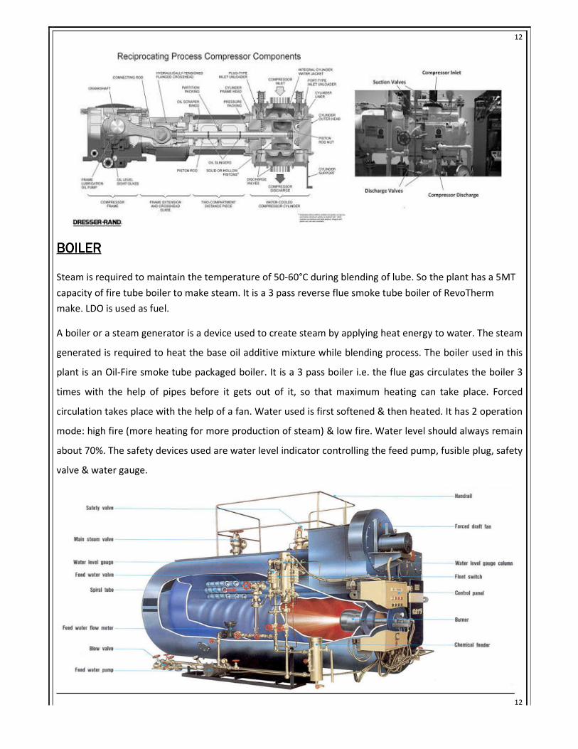
BOILERBOILERBOILERBOILER
Steam is required to maintain the temperature of 50-60°C during blending of lube. So the plant has a 5MT
capacity of fire tube boiler to make steam. It is a 3 pass reverse flue smoke tube boiler of RevoTherm
make. LDO is used as fuel.
A boiler or a steam generator is a device used to create steam by applying heat energy to water. The steam
generated is required to heat the base oil additive mixture while blending process. The boiler used in this
plant is an Oil-Fire smoke tube packaged boiler. It is a 3 pass boiler i.e. the flue gas circulates the boiler 3
times with the help of pipes before it gets out of it, so that maximum heating can take place. Forced
circulation takes place with the help of a fan. Water used is first softened & then heated. It has 2 operation
mode: high fire (more heating for more production of steam) & low fire. Water level should always remain
about 70%. The safety devices used are water level indicator controlling the feed pump, fusible plug, safety
valve & water gauge.
Page 13
13
13
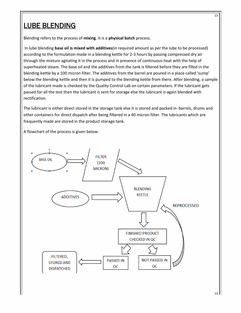
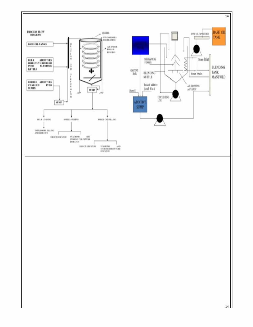
LUBE LUBE LUBE LUBE BLENDINGBLENDINGBLENDINGBLENDING
Blending refers to the process of mixing. It is a physical batch process.
In lube blending base oil is mixed with additives(in required amount as per the lube to be processed)
according to the formulation made in a blending kettle for 2-3 hours by passing compressed dry air
through the mixture agitating it in the process and in presence of continuous heat with the help of
superheated steam. The base oil and the additives from the tank is filtered before they are filled in the
blending kettle by a 100 micron filter. The additives from the barrel are poured in a place called ‘sump’
below the blending kettle and then it is pumped to the blending kettle from there. After blending, a sample
of the lubricant made is checked by the Quality Control Lab on certain parameters. If the lubricant gets
passed for all the test then the lubricant is sent for storage else the lubricant is again blended with
rectification.
The lubricant is either direct stored in the storage tank else it is stored and packed in barrels, drums and
other containers for direct dispatch after being filtered in a 40 micron filter. The lubricants which are
frequently made are stored in the product storage tank.
A flowchart of the process is given below:
Page 15
15
15
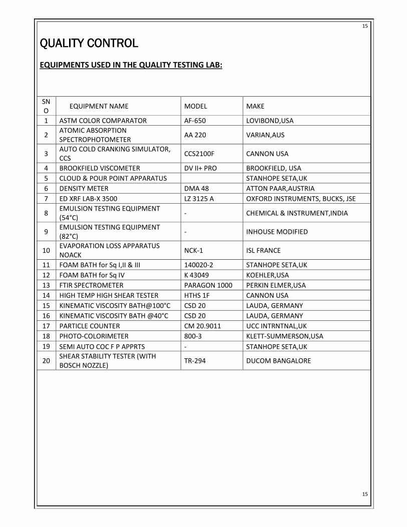
QUALITY QUALITY QUALITY QUALITY CONTROLCONTROLCONTROLCONTROL
EQUIPMENTS USED IN THE QUALITY TESTING LAB:
SN
O EQUIPMENT NAME MODEL MAKE
1 ASTM COLOR COMPARATOR AF-650 LOVIBOND,USA
2 ATOMIC ABSORPTION
SPECTROPHOTOMETER AA 220 VARIAN,AUS
3 AUTO COLD CRANKING SIMULATOR,
CCS CCS2100F CANNON USA
4 BROOKFIELD VISCOMETER DV II+ PRO BROOKFIELD, USA
5 CLOUD & POUR POINT APPARATUS STANHOPE SETA,UK
6 DENSITY METER DMA 48 ATTON PAAR,AUSTRIA
7 ED XRF LAB-X 3500 LZ 3125 A OXFORD INSTRUMENTS, BUCKS, JSE
8 EMULSION TESTING EQUIPMENT
(54°C) - CHEMICAL & INSTRUMENT,INDIA
9 EMULSION TESTING EQUIPMENT
(82°C) - INHOUSE MODIFIED
10 EVAPORATION LOSS APPARATUS
NOACK NCK-1 ISL FRANCE
11 FOAM BATH for Sq I,II & III 140020-2 STANHOPE SETA,UK
12 FOAM BATH for Sq IV K 43049 KOEHLER,USA
13 FTIR SPECTROMETER PARAGON 1000 PERKIN ELMER,USA
14 HIGH TEMP HIGH SHEAR TESTER HTHS 1F CANNON USA
15 KINEMATIC VISCOSITY BATH@100°C CSD 20 LAUDA, GERMANY
16 KINEMATIC VISCOSITY BATH @40°C CSD 20 LAUDA, GERMANY
17 PARTICLE COUNTER CM 20.9011 UCC INTRNTNAL,UK
18 PHOTO-COLORIMETER 800-3 KLETT-SUMMERSON,USA
19 SEMI AUTO COC F P APPRTS - STANHOPE SETA,UK
20 SHEAR STABILITY TESTER (WITH
BOSCH NOZZLE) TR-294 DUCOM BANGALORE
Page 16
16
16
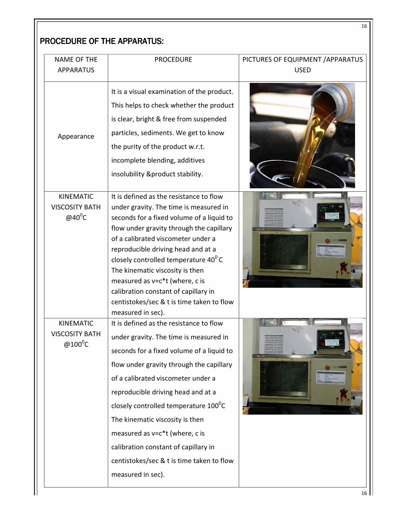
PROCEDURE PROCEDURE PROCEDURE PROCEDURE OF THE APPARATUSOF THE APPARATUSOF THE APPARATUSOF THE APPARATUS::::
NAME OF THE
APPARATUS
PROCEDURE PICTURES OF EQUIPMENT /APPARATUS
USED
Appearance
It is a visual examination of the product.
This helps to check whether the product
is clear, bright & free from suspended
particles, sediments. We get to know
the purity of the product w.r.t.
incomplete blending, additives
insolubility &product stability.
KINEMATIC
VISCOSITY BATH
@400C
It is defined as the resistance to flow
under gravity. The time is measured in
seconds for a fixed volume of a liquid to
flow under gravity through the capillary
of a calibrated viscometer under a
reproducible driving head and at a
closely controlled temperature 400∙
C
The kinematic viscosity is then
measured as v=c*t (where, c is
calibration constant of capillary in
centistokes/sec & t is time taken to flow
measured in sec).
KINEMATIC
VISCOSITY BATH
@1000C
It is defined as the resistance to flow
under gravity. The time is measured in
seconds for a fixed volume of a liquid to
flow under gravity through the capillary
of a calibrated viscometer under a
reproducible driving head and at a
closely controlled temperature 1000C
The kinematic viscosity is then
measured as v=c*t (where, c is
calibration constant of capillary in
centistokes/sec & t is time taken to flow
measured in sec).
Page 17
17
17
Viscosity index
(ASTM D 2270)
The viscosities of lubricating oils change
rapidly with temperature. The rate of
change of viscosity varies with the type
of oil. The rate of change of kinematic
viscosity with temperature is indicated
by the viscosity index. It is found with
the help of the viscosity at 2 different
temperatures (mainly 40 &100∙C) from
the V.I. chart.
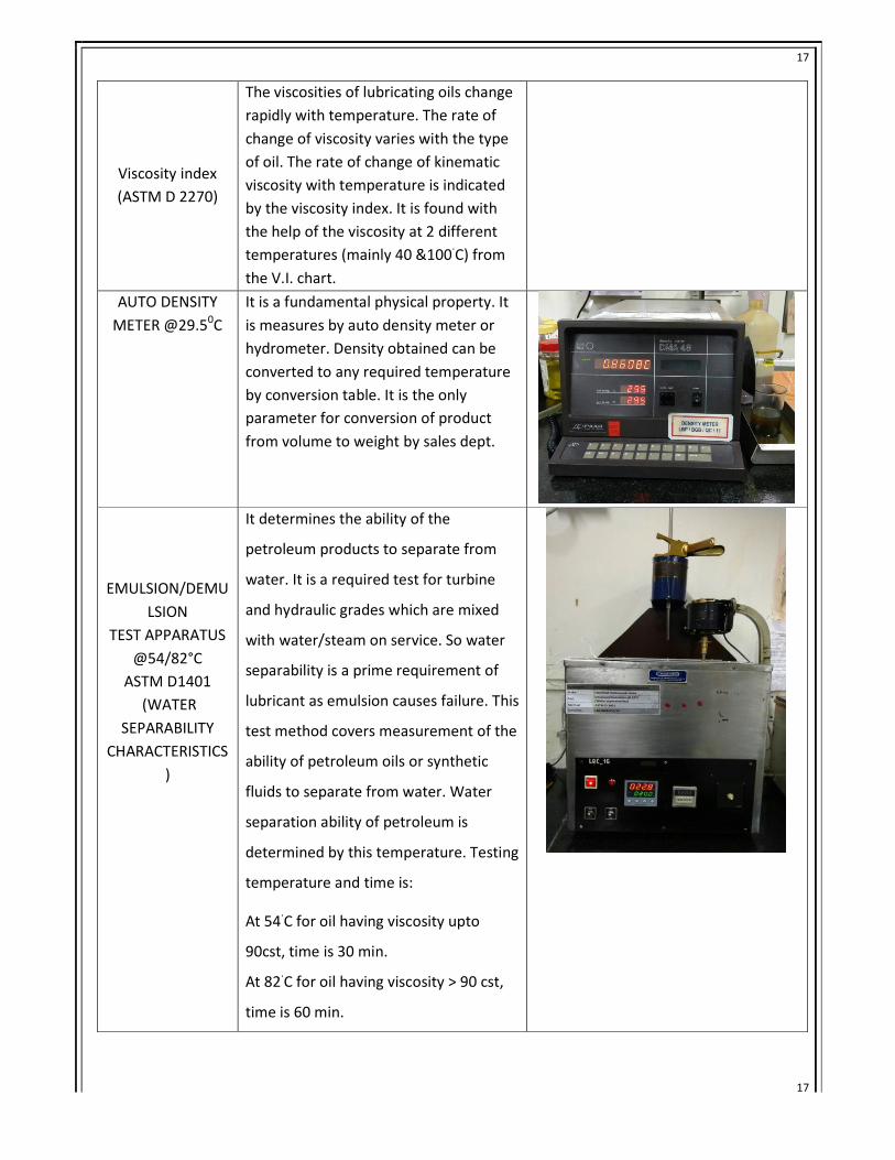
AUTO DENSITY
METER @29.50C
It is a fundamental physical property. It
is measures by auto density meter or
hydrometer. Density obtained can be
converted to any required temperature
by conversion table. It is the only
parameter for conversion of product
from volume to weight by sales dept.
EMULSION/DEMU
LSION
TEST APPARATUS
@54/82°C
ASTM D1401
(WATER
SEPARABILITY
CHARACTERISTICS
)
It determines the ability of the
petroleum products to separate from
water. It is a required test for turbine
and hydraulic grades which are mixed
with water/steam on service. So water
separability is a prime requirement of
lubricant as emulsion causes failure. This
test method covers measurement of the
ability of petroleum oils or synthetic
fluids to separate from water. Water
separation ability of petroleum is
determined by this temperature. Testing
temperature and time is:
At 54∙C for oil having viscosity upto
90cst, time is 30 min.
At 82∙C for oil having viscosity > 90 cst,
time is 60 min.
Page 18
18
18
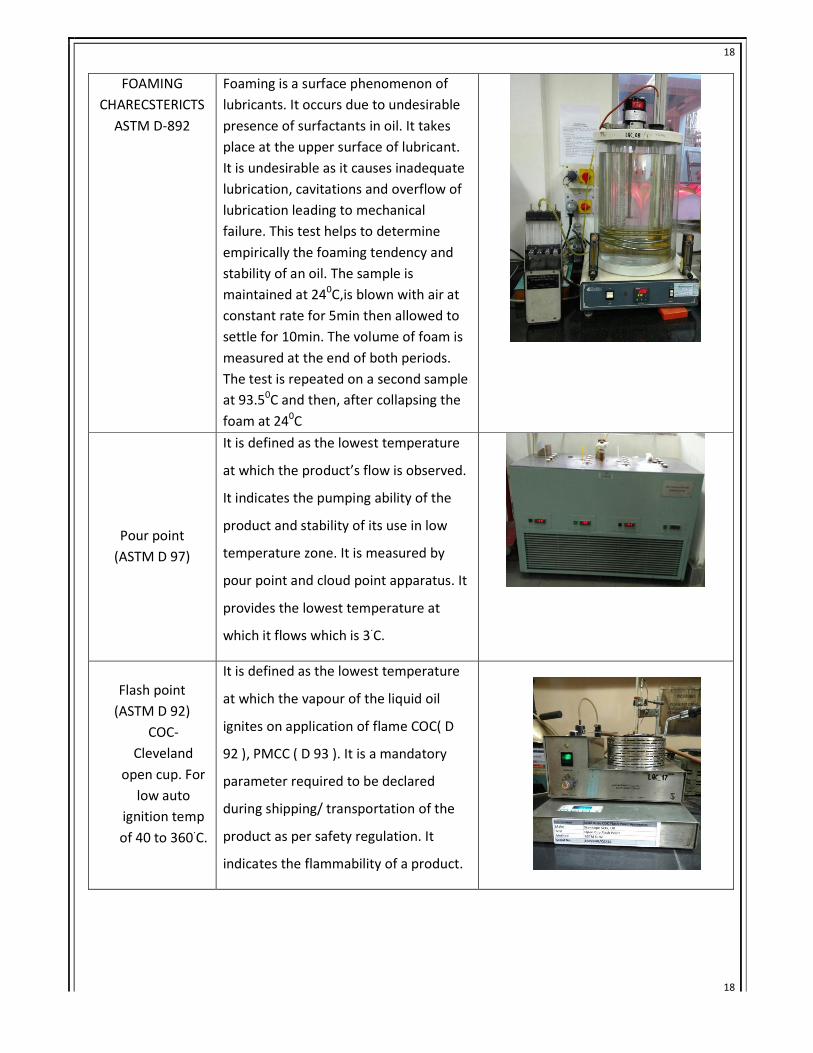
FOAMING
CHARECSTERICTS
ASTM D-892
Foaming is a surface phenomenon of
lubricants. It occurs due to undesirable
presence of surfactants in oil. It takes
place at the upper surface of lubricant.
It is undesirable as it causes inadequate
lubrication, cavitations and overflow of
lubrication leading to mechanical
failure. This test helps to determine
empirically the foaming tendency and
stability of an oil. The sample is
maintained at 240C,is blown with air at
constant rate for 5min then allowed to
settle for 10min. The volume of foam is
measured at the end of both periods.
The test is repeated on a second sample
at 93.50C and then, after collapsing the
foam at 240C
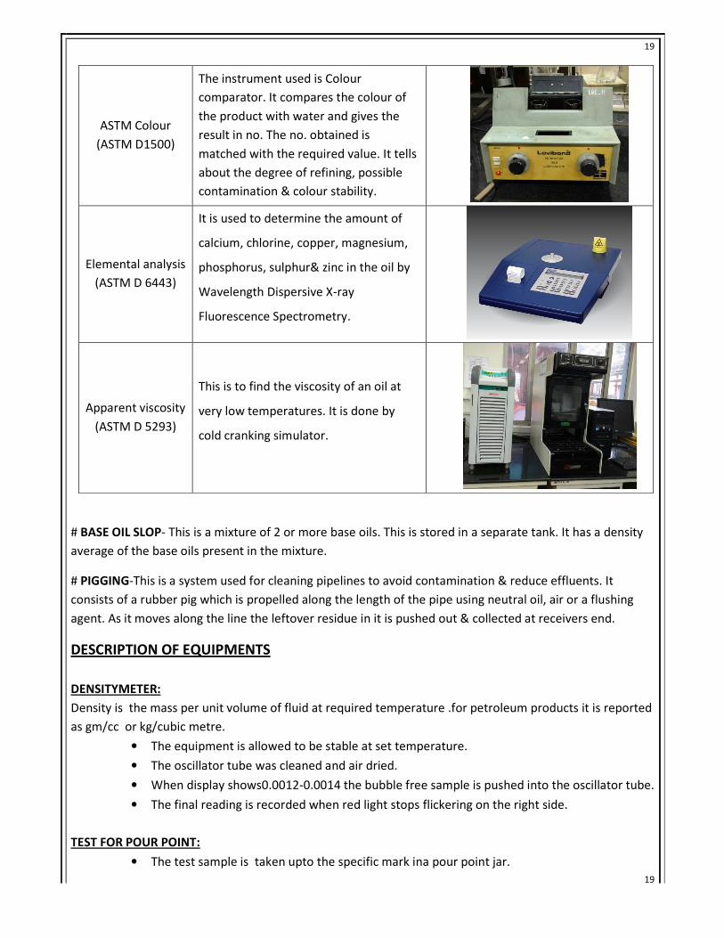
Pour point
(ASTM D 97)
It is defined as the lowest temperature
at which the product’s flow is observed.
It indicates the pumping ability of the
product and stability of its use in low
temperature zone. It is measured by
pour point and cloud point apparatus. It
provides the lowest temperature at
which it flows which is 3∙C.
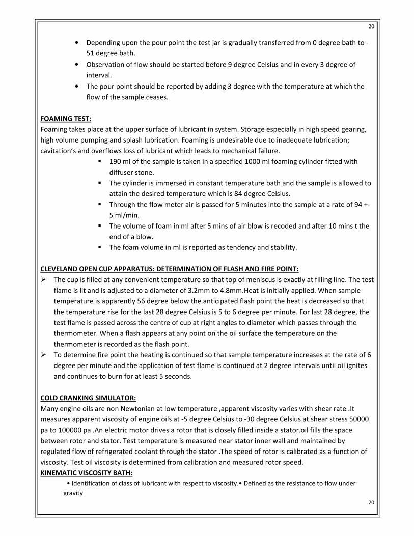
Flash point
(ASTM D 92)
COC-
Cleveland
open cup. For
low auto
ignition temp
of 40 to 360∙C.
It is defined as the lowest temperature
at which the vapour of the liquid oil
ignites on application of flame COC( D
92 ), PMCC ( D 93 ). It is a mandatory
parameter required to be declared
during shipping/ transportation of the
product as per safety regulation. It
indicates the flammability of a product.
Page 19
19
19
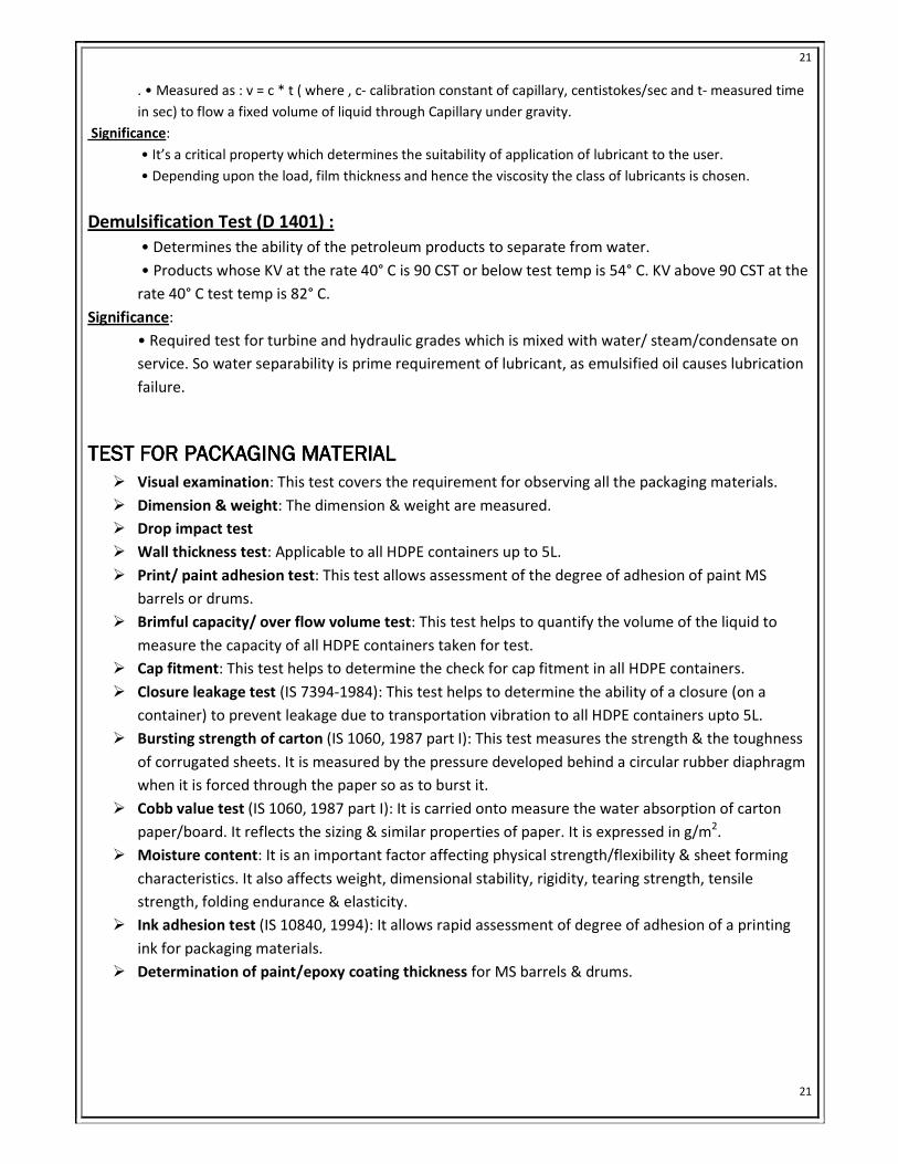
ASTM Colour
(ASTM D1500)
The instrument used is Colour
comparator. It compares the colour of
the product with water and gives the
result in no. The no. obtained is
matched with the required value. It tells
about the degree of refining, possible
contamination & colour stability.
Elemental analysis
(ASTM D 6443)
It is used to determine the amount of
calcium, chlorine, copper, magnesium,
phosphorus, sulphur& zinc in the oil by
Wavelength Dispersive X-ray
Fluorescence Spectrometry.
Apparent viscosity
(ASTM D 5293)
This is to find the viscosity of an oil at
very low temperatures. It is done by
cold cranking simulator.
# BASE OIL SLOP- This is a mixture of 2 or more base oils. This is stored in a separate tank. It has a density
average of the base oils present in the mixture.
# PIGGING-This is a system used for cleaning pipelines to avoid contamination & reduce effluents. It
consists of a rubber pig which is propelled along the length of the pipe using neutral oil, air or a flushing
agent. As it moves along the line the leftover residue in it is pushed out & collected at receivers end.
DESCRIPTION OF EQUIPMENTS
DENSITYMETER:
Density is the mass per unit volume of fluid at required temperature .for petroleum products it is reported
as gm/cc or kg/cubic metre.
• The equipment is allowed to be stable at set temperature.
• The oscillator tube was cleaned and air dried.
• When display shows0.0012-0.0014 the bubble free sample is pushed into the oscillator tube.
• The final reading is recorded when red light stops flickering on the right side.
TEST FOR POUR POINT:
• The test sample is taken upto the specific mark ina pour point jar.
Page 20
20
20
• Depending upon the pour point the test jar is gradually transferred from 0 degree bath to -
51 degree bath.
• Observation of flow should be started before 9 degree Celsius and in every 3 degree of
interval.
• The pour point should be reported by adding 3 degree with the temperature at which the
flow of the sample ceases.
FOAMING TEST:
Foaming takes place at the upper surface of lubricant in system. Storage especially in high speed gearing,
high volume pumping and splash lubrication. Foaming is undesirable due to inadequate lubrication;
cavitation’s and overflows loss of lubricant which leads to mechanical failure.
� 190 ml of the sample is taken in a specified 1000 ml foaming cylinder fitted with
diffuser stone.
� The cylinder is immersed in constant temperature bath and the sample is allowed to
attain the desired temperature which is 84 degree Celsius.
� Through the flow meter air is passed for 5 minutes into the sample at a rate of 94 +-
5 ml/min.
� The volume of foam in ml after 5 mins of air blow is recoded and after 10 mins t the
end of a blow.
� The foam volume in ml is reported as tendency and stability.
CLEVELAND OPEN CUP APPARATUS: DETERMINATION OF FLASH AND FIRE POINT:
� The cup is filled at any convenient temperature so that top of meniscus is exactly at filling line. The test
flame is lit and is adjusted to a diameter of 3.2mm to 4.8mm.Heat is initially applied. When sample
temperature is apparently 56 degree below the anticipated flash point the heat is decreased so that
the temperature rise for the last 28 degree Celsius is 5 to 6 degree per minute. For last 28 degree, the
test flame is passed across the centre of cup at right angles to diameter which passes through the
thermometer. When a flash appears at any point on the oil surface the temperature on the
thermometer is recorded as the flash point.
� To determine fire point the heating is continued so that sample temperature increases at the rate of 6
degree per minute and the application of test flame is continued at 2 degree intervals until oil ignites
and continues to burn for at least 5 seconds.
COLD CRANKING SIMULATOR:
Many engine oils are non Newtonian at low temperature ,apparent viscosity varies with shear rate .It
measures apparent viscosity of engine oils at -5 degree Celsius to -30 degree Celsius at shear stress 50000
pa to 100000 pa .An electric motor drives a rotor that is closely filled inside a stator.oil fills the space
between rotor and stator. Test temperature is measured near stator inner wall and maintained by
regulated flow of refrigerated coolant through the stator .The speed of rotor is calibrated as a function of
viscosity. Test oil viscosity is determined from calibration and measured rotor speed.
KINEMATIC VISCOSITY BATH:
• Identification of class of lubricant with respect to viscosity.• Defined as the resistance to flow under
gravity
Page 21
21
21
. • Measured as : v = c * t ( where , c- calibration constant of capillary, centistokes/sec and t- measured time
in sec) to flow a fixed volume of liquid through Capillary under gravity.
Significance:
• It’s a critical property which determines the suitability of application of lubricant to the user.
• Depending upon the load, film thickness and hence the viscosity the class of lubricants is chosen.
Demulsification Test (D 1401) :
• Determines the ability of the petroleum products to separate from water.
• Products whose KV at the rate 40° C is 90 CST or below test temp is 54° C. KV above 90 CST at the
rate 40° C test temp is 82° C.
Significance:
• Required test for turbine and hydraulic grades which is mixed with water/ steam/condensate on
service. So water separability is prime requirement of lubricant, as emulsified oil causes lubrication
failure.
TEST FORTEST FORTEST FORTEST FOR PACKAGING MATERIALPACKAGING MATERIALPACKAGING MATERIALPACKAGING MATERIAL
� Visual examination: This test covers the requirement for observing all the packaging materials.
� Dimension & weight: The dimension & weight are measured.
� Drop impact test
� Wall thickness test: Applicable to all HDPE containers up to 5L.
� Print/ paint adhesion test: This test allows assessment of the degree of adhesion of paint MS
barrels or drums.
� Brimful capacity/ over flow volume test: This test helps to quantify the volume of the liquid to
measure the capacity of all HDPE containers taken for test.
� Cap fitment: This test helps to determine the check for cap fitment in all HDPE containers.
� Closure leakage test (IS 7394-1984): This test helps to determine the ability of a closure (on a
container) to prevent leakage due to transportation vibration to all HDPE containers upto 5L.
� Bursting strength of carton (IS 1060, 1987 part I): This test measures the strength & the toughness
of corrugated sheets. It is measured by the pressure developed behind a circular rubber diaphragm
when it is forced through the paper so as to burst it.
� Cobb value test (IS 1060, 1987 part I): It is carried onto measure the water absorption of carton
paper/board. It reflects the sizing & similar properties of paper. It is expressed in g/m2.
� Moisture content: It is an important factor affecting physical strength/flexibility & sheet forming
characteristics. It also affects weight, dimensional stability, rigidity, tearing strength, tensile
strength, folding endurance & elasticity.
� Ink adhesion test (IS 10840, 1994): It allows rapid assessment of degree of adhesion of a printing
ink for packaging materials.
� Determination of paint/epoxy coating thickness for MS barrels & drums.
Page 22
22
22
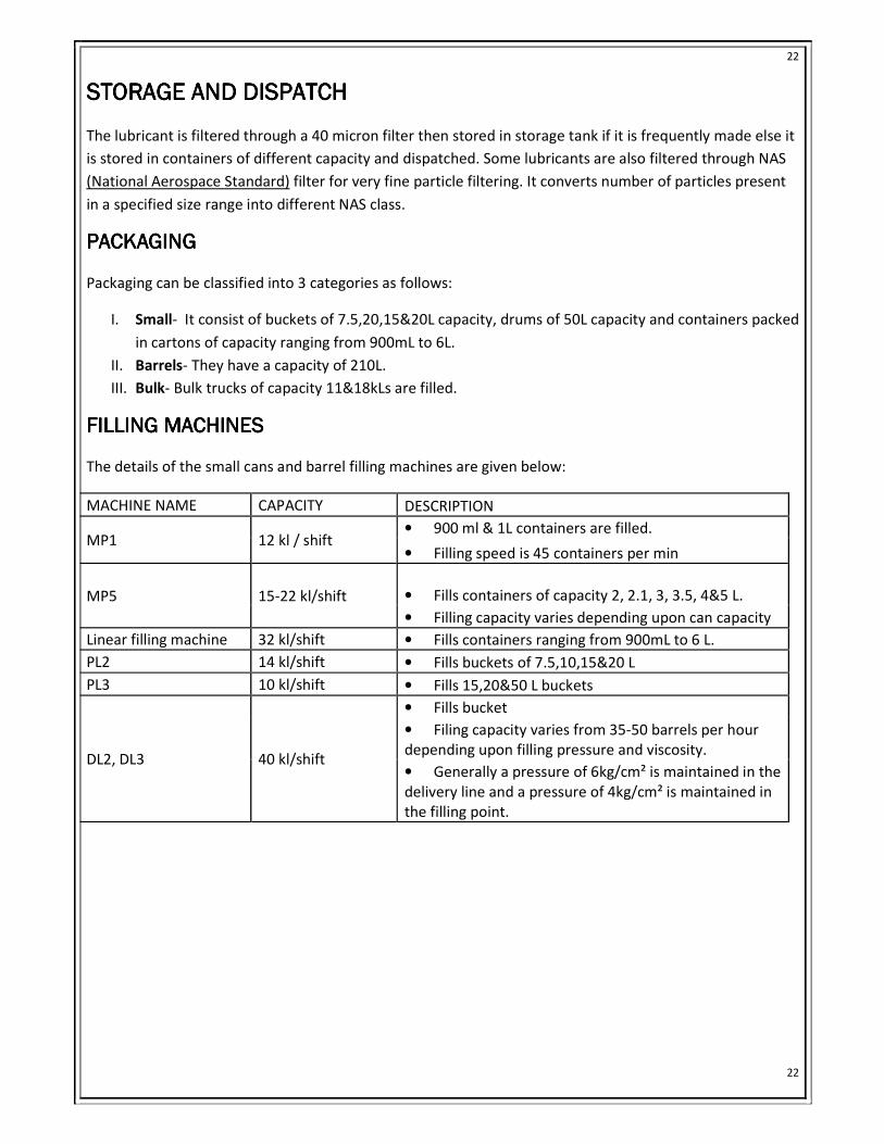
STORAGE AND DISPATCHSTORAGE AND DISPATCHSTORAGE AND DISPATCHSTORAGE AND DISPATCH
The lubricant is filtered through a 40 micron filter then stored in storage tank if it is frequently made else it
is stored in containers of different capacity and dispatched. Some lubricants are also filtered through NAS
(National Aerospace Standard) filter for very fine particle filtering. It converts number of particles present
in a specified size range into different NAS class.
PACKAGINGPACKAGINGPACKAGINGPACKAGING
Packaging can be classified into 3 categories as follows:
I. Small- It consist of buckets of 7.5,20,15&20L capacity, drums of 50L capacity and containers packed
in cartons of capacity ranging from 900mL to 6L.
II. Barrels- They have a capacity of 210L.
III. Bulk- Bulk trucks of capacity 11&18kLs are filled.
FILLING MACHINESFILLING MACHINESFILLING MACHINESFILLING MACHINES
The details of the small cans and barrel filling machines are given below:
MACHINE NAME CAPACITY DESCRIPTION
MP1 12 kl / shift • 900 ml & 1L containers are filled.
• Filling speed is 45 containers per min
MP5 15-22 kl/shift • Fills containers of capacity 2, 2.1, 3, 3.5, 4&5 L.
• Filling capacity varies depending upon can capacity
Linear filling machine 32 kl/shift • Fills containers ranging from 900mL to 6 L.
PL2 14 kl/shift • Fills buckets of 7.5,10,15&20 L
PL3 10 kl/shift • Fills 15,20&50 L buckets
DL2, DL3 40 kl/shift
• Fills bucket
• Filing capacity varies from 35-50 barrels per hour
depending upon filling pressure and viscosity.
• Generally a pressure of 6kg/cm² is maintained in the
delivery line and a pressure of 4kg/cm² is maintained in
the filling point.
Page 23
23
23
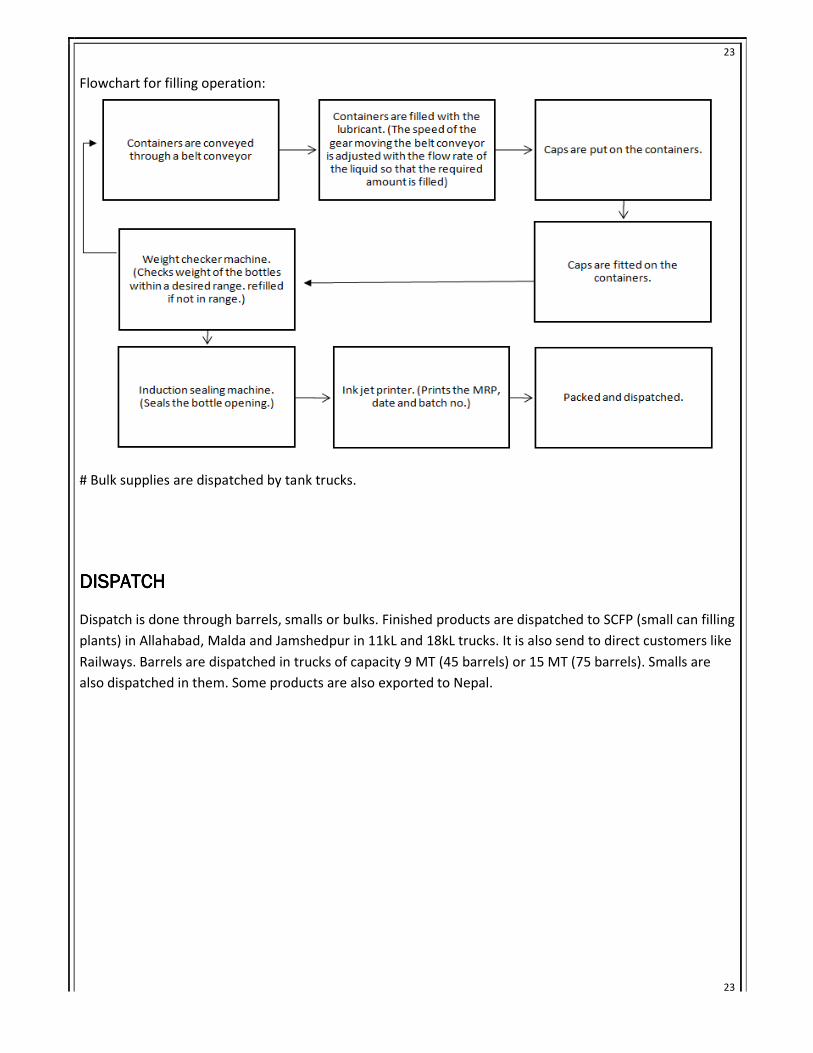
Flowchart for filling operation:
# Bulk supplies are dispatched by tank trucks.
DISPATCHDISPATCHDISPATCHDISPATCH
Dispatch is done through barrels, smalls or bulks. Finished products are dispatched to SCFP (small can filling
plants) in Allahabad, Malda and Jamshedpur in 11kL and 18kL trucks. It is also send to direct customers like
Railways. Barrels are dispatched in trucks of capacity 9 MT (45 barrels) or 15 MT (75 barrels). Smalls are
also dispatched in them. Some products are also exported to Nepal.
Page 24
24
24
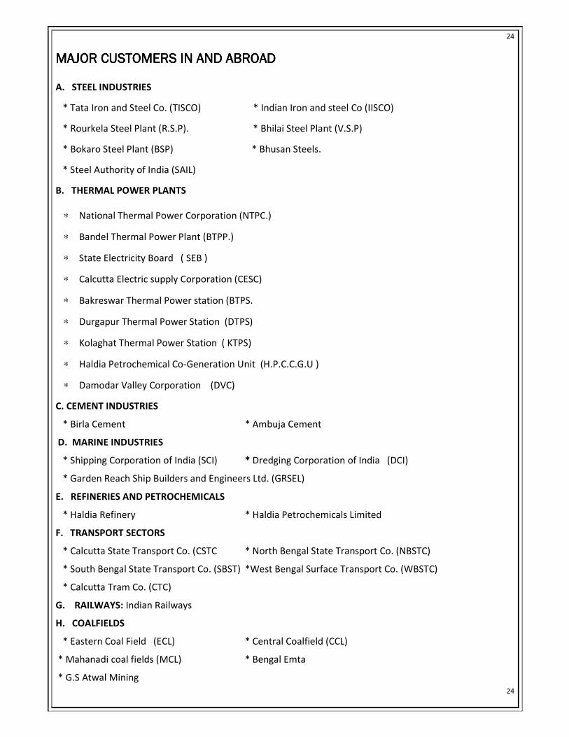
MAJOR CUSTOMERS IN AND ABROADMAJOR CUSTOMERS IN AND ABROADMAJOR CUSTOMERS IN AND ABROADMAJOR CUSTOMERS IN AND ABROAD
A. STEEL INDUSTRIES
* Tata Iron and Steel Co. (TISCO) * Indian Iron and steel Co (IISCO)
* Rourkela Steel Plant (R.S.P). * Bhilai Steel Plant (V.S.P)
* Bokaro Steel Plant (BSP) * Bhusan Steels.
* Steel Authority of India (SAIL)
B. THERMAL POWER PLANTS
∗ National Thermal Power Corporation (NTPC.)
∗ Bandel Thermal Power Plant (BTPP.)
∗ State Electricity Board ( SEB )
∗ Calcutta Electric supply Corporation (CESC)
∗ Bakreswar Thermal Power station (BTPS.
∗ Durgapur Thermal Power Station (DTPS)
∗ Kolaghat Thermal Power Station ( KTPS)
∗ Haldia Petrochemical Co-Generation Unit (H.P.C.C.G.U )
∗ Damodar Valley Corporation (DVC)
C. CEMENT INDUSTRIES
* Birla Cement * Ambuja Cement
D. MARINE INDUSTRIES
* Shipping Corporation of India (SCI) * Dredging Corporation of India (DCI)
* Garden Reach Ship Builders and Engineers Ltd. (GRSEL)
E. REFINERIES AND PETROCHEMICALS
* Haldia Refinery * Haldia Petrochemicals Limited
F. TRANSPORT SECTORS
* Calcutta State Transport Co. (CSTC * North Bengal State Transport Co. (NBSTC)
* South Bengal State Transport Co. (SBST) *West Bengal Surface Transport Co. (WBSTC)
* Calcutta Tram Co. (CTC)
G. RAILWAYS: Indian Railways
H. COALFIELDS
* Eastern Coal Field (ECL) * Central Coalfield (CCL)
* Mahanadi coal fields (MCL) * Bengal Emta
* G.S Atwal Mining
Page 25
25
25
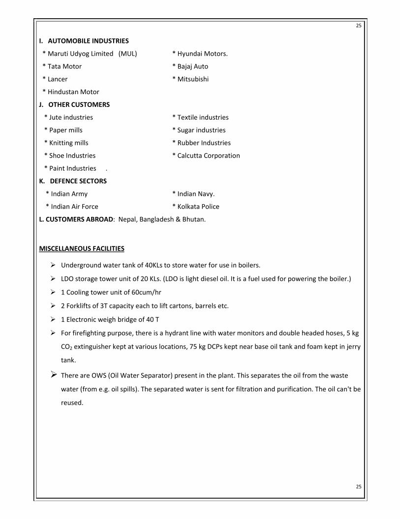
I. AUTOMOBILE INDUSTRIES
* Maruti Udyog Limited (MUL) * Hyundai Motors.
* Tata Motor * Bajaj Auto
* Lancer * Mitsubishi
* Hindustan Motor
J. OTHER CUSTOMERS
* Jute industries * Textile industries
* Paper mills * Sugar industries
* Knitting mills * Rubber Industries
* Shoe Industries * Calcutta Corporation
* Paint Industries .
K. DEFENCE SECTORS
* Indian Army * Indian Navy.
* Indian Air Force * Kolkata Police
L. CUSTOMERS ABROAD: Nepal, Bangladesh & Bhutan.
MISCELLANEOUS FACILITIES
� Underground water tank of 40KLs to store water for use in boilers.
� LDO storage tower unit of 20 KLs. (LDO is light diesel oil. It is a fuel used for powering the boiler.)
� 1 Cooling tower unit of 60cum/hr
� 2 Forklifts of 3T capacity each to lift cartons, barrels etc.
� 1 Electronic weigh bridge of 40 T
� For firefighting purpose, there is a hydrant line with water monitors and double headed hoses, 5 kg
CO2 extinguisher kept at various locations, 75 kg DCPs kept near base oil tank and foam kept in jerry
tank.
� There are OWS (Oil Water Separator) present in the plant. This separates the oil from the waste
water (from e.g. oil spills). The separated water is sent for filtration and purification. The oil can't be
reused.
Page 26
26
26
SAFETYSAFETYSAFETYSAFETY
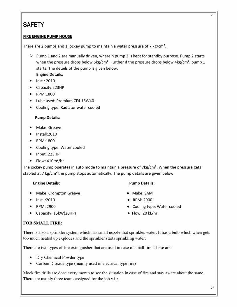
FIRE ENGINE PUMP HOUSE
There are 2 pumps and 1 jockey pump to maintain a water pressure of 7 kg/cm².
� Pump 1 and 2 are manually driven, wherein pump 2 is kept for standby purpose. Pump 2 starts
when the pressure drops below 5kg/cm². Further if the pressure drops below 4kg/cm², pump 1
starts. The details of the pump is given below:
Engine Details:
• Inst.: 2010
• Capacity:223HP
• RPM:1800
• Lube used: Premium CF4 16W40
• Cooling type: Radiator water cooled
Pump Details:
• Make: Greave
• Install:2010
• RPM:1800
• Cooling type: Water cooled
• Input: 223HP
• Flow: 410m³/hr
The jockey pump operates in auto mode to maintain a pressure of 7kg/cm². When the pressure gets
stabled at 7 kg/cm2 the pump stops automatically. The pump details are given below:
Engine Details: Pump Details:
• Make: Crompton Greave ● Make: SAM
• Inst. :2010 ● RPM: 2900
• RPM: 2900 ● Cooling type: Water cooled
• Capacity: 15kW(20HP) ● Flow: 20 kL/hr
FOR SMALL FIRE:
There is also a sprinkler system which has small nozzle that sprinkles water. It has a bulb which when gets
too much heated up explodes and the sprinkler starts sprinkling water.
There are two types of fire extinguisher that are used in case of small fire. These are:
• Dry Chemical Powder type
• Carbon Dioxide type (mainly used in electrical type fire)
Mock fire drills are done every month to see the situation in case of fire and stay aware about the same.
There are mainly three teams assigned for the job v.i.z.
Page 27
27
27
• Combating team
• Rescue team
• Auxiliary team
LAB SCALE BLENDING AND TESTING
SERVO PREMIUM CF-4 15W40
DESCRIPTION:
Servo Premium CF-4 15W-40 is a premium quality, API certified, commercial multipurpose diesel engine oil. The oil is
designed for the most severe performance requirements of modern, highly rated turbo charged diesel engines in the
over the road transport fleet applications and also off highway operations. It assures outstanding protection against
high temperature engine deposits, oil degradation, and oil thickening and corrosion resistance. The oil is having
excellent shear stability to maintain viscosity under severe, high temperature operations.
PERFORMANCE BENEFITS
• Reduced engine scuffing and bore polishing
• High engine cleanliness
• . Maximum protection from wear and deposits.
• Suitable for mixed fleet operation.
• Improved control of oil consumption
• Easier cold starting.
• Excellent all weather performance due to improved cold weather properties
• Catalytic Converter compatible
APPLICATIONS: Servo Premium CF-4 15W-40 is recommended for new generation commercial diesel
vehicles of both American and European design such as Caterpillar and Cummins operating on Heavy duty
on-highway and off-highway equipments.
HEALTH AND SAFETY:
These oils are unlikely to present any significant health or safety hazard when properly used in the
recommended application and good standards of industrial and personal hygiene are maintained.
Page 28
28
28
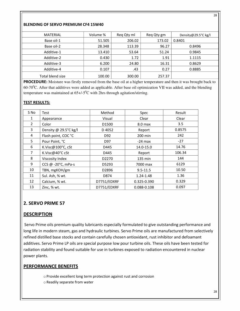
BLENDING OF SERVO PREMIUM CF4 15W40
MATERIAL Volume % Req Qty ml Req Qty gm [email protected] °C kg/l
Base oil-1 51.505 206.02 173.02 0.8401
Base oil-2 28.348 113.39 96.27 0.8496
Additive-1 13.410 53.64 51.24 0.9845
Additive-2 0.430 1.72 1.91 1.1115
Additive-3 6.200 24.80 16.31 0.8629
Additive-4 0.107 .43 0.27 0.8885
Total blend size 100.00 300.00 257.37
PROCEDURE: Moisture was firstly removed from the base oil at a higher temperature and then it was brought back to
60-700C. After that additives were added as applicable. After base oil optimization VII was added, and the blending
temperature was maintained at 65+/-50C with 2hrs through agitation/stirring.
TEST RESULTS:
S No Test Method Spec Result
1 Appearance Visual Clear Clear
2 Color D1500 8.0 max 3.5
3 Density @ 29.5°C kg/l D 4052 Report 0.8575
4 Flash point, COC °C D92 200 min 242
5 Pour Point, °C D97 -24 max -27
6 K.Visc@100°C, cSt D445 14.0-15.0 14.76
7 K.Visc@40°C cSt D445 Report 106.34
8 Viscosity Index D2270 135 min 144
9 CCS @ -20°C, mPa-s D5293 7000 max 6129
10 TBN, mgKOH/gm D2896 9.5-11.5 10.50
11 Sul. Ash, % wt. D874 1.24-1.48 1.36
12 Calcium, % wt. D7751/EDXRF 0.325-0.390 0.329
13 Zinc, % wt. D7751/EDXRF 0.088-0.108 0.097
2. SERVO PRIME 57
DESCRIPTION
Servo Prime oils premium quality lubricants especially formulated to give outstanding performance and
long life in modern steam, gas and hydraulic turbines. Servo Prime oils are manufactured from selectively
refined distilled base stocks and contain carefully chosen antioxidant, rust inhibitor and defoamant
additives. Servo Prime LP oils are special purpose low pour turbine oils. These oils have been tested for
radiation stability and found suitable for use in turbines exposed to radiation encountered in nuclear
power plants.
PERFORMANCE BENEFITS
o Provide excellent long term protection against rust and corrosion
o Readily separate from water
Page 29
29
29
o Ensure long service life since they possess outstanding oxidation stability
o Reduced tendency to foam
o Able to release entrained air at a rapid rate
APPLICATIONS: Servo prime oils are recommended for use in the lubrication system of steam, gas and
hydraulic turbines operating under all service conditions. In addition, Servoprime oils give outstanding
performance in hydraulic systems, circulating lubrication systems, enclosed bearings and other industrial
machines in which long trouble free service of lubricant is required. Servoprime LP oils are meant for low
temperature applications such as Roto flow expanders and Turbo compressors used in refrigeration
applications
HEALTH AND SAFETY:
These oils are unlikely to present any significant health or safety hazard when properly used in the
recommended application and good standards of industrial and personal hygiene are maintained.
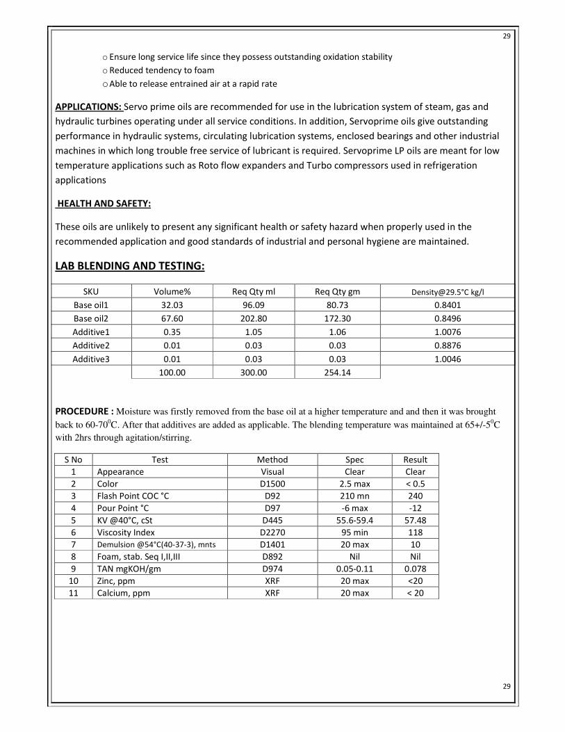
LAB BLENDING AND TESTING:
SKU Volume% Req Qty ml Req Qty gm [email protected] °C kg/l
Base oil1 32.03 96.09 80.73 0.8401
Base oil2 67.60 202.80 172.30 0.8496
Additive1 0.35 1.05 1.06 1.0076
Additive2 0.01 0.03 0.03 0.8876
Additive3 0.01 0.03 0.03 1.0046
100.00 300.00 254.14
PROCEDURE : Moisture was firstly removed from the base oil at a higher temperature and and then it was brought
back to 60-700C. After that additives are added as applicable. The blending temperature was maintained at 65+/-5
0C
with 2hrs through agitation/stirring.
S No Test Method Spec Result
1 Appearance Visual Clear Clear
2 Color D1500 2.5 max < 0.5
3 Flash Point COC °C D92 210 mn 240
4 Pour Point °C D97 -6 max -12
5 KV @40°C, cSt D445 55.6-59.4 57.48
6 Viscosity Index D2270 95 min 118
7 Demulsion @54°C(40-37-3), mnts D1401 20 max 10
8 Foam, stab. Seq I,II,III D892 Nil Nil
9 TAN mgKOH/gm D974 0.05-0.11 0.078
10 Zinc, ppm XRF 20 max <20
11 Calcium, ppm XRF 20 max < 20
Page 30
30
30
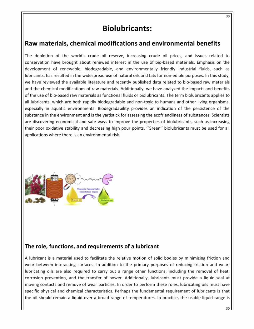
Biolubricants:
Raw materials, chemical modifications and environmental benefits
The depletion of the world’s crude oil reserve, increasing crude oil prices, and issues related to
conservation have brought about renewed interest in the use of bio-based materials. Emphasis on the
development of renewable, biodegradable, and environmentally friendly industrial fluids, such as
lubricants, has resulted in the widespread use of natural oils and fats for non-edible purposes. In this study,
we have reviewed the available literature and recently published data related to bio-based raw materials
and the chemical modifications of raw materials. Additionally, we have analyzed the impacts and benefits
of the use of bio-based raw materials as functional fluids or biolubricants. The term biolubricants applies to
all lubricants, which are both rapidly biodegradable and non-toxic to humans and other living organisms,
especially in aquatic environments. Biodegradability provides an indication of the persistence of the
substance in the environment and is the yardstick for assessing the ecofriendliness of substances. Scientists
are discovering economical and safe ways to improve the properties of biolubricants, such as increasing
their poor oxidative stability and decreasing high pour points. ‘‘Green’’ biolubricants must be used for all
applications where there is an environmental risk.
The role, functions, and requirements of a lubricant
A lubricant is a material used to facilitate the relative motion of solid bodies by minimizing friction and
wear between interacting surfaces. In addition to the primary purposes of reducing friction and wear,
lubricating oils are also required to carry out a range other functions, including the removal of heat,
corrosion prevention, and the transfer of power. Additionally, lubricants must provide a liquid seal at
moving contacts and remove of wear particles. In order to perform these roles, lubricating oils must have
specific physical and chemical characteristics. Perhaps the fundamental requirement of lubricants is that
the oil should remain a liquid over a broad range of temperatures. In practice, the usable liquid range is
Page 31
31
31
limited by the pour point (PP) at low temperatures and the flash point at high temperatures. The PP should
be low to ensure that the lubricant is pump-able when the equipment is started from extremely low
temperatures . The flash point should be high to allow the safe operation and minimum volatilization at
the maximum operating temperature. For the most demanding applications, such as aviation jet engine
lubricants, an effective liquid range over 3008C may be required. The efficiency of the lubricant in reducing
friction and wear is greatly influenced by its viscosity. The relationship between speed, viscosity, load, oil
film thickness, and friction is illustrated by the Stribeck diagram. Furthermore, biodegradability is the most
important aspect with regard to the environmental fate of a substance. Primary degradation is the first
step in the breakdown of a substance and involves the disappearance of the original molecule. However,
the determination of the ultimate degradability or the mineralization of substances to CO2, H2O, and the
formation of biomass is important. Ultimate biodegradability guarantees the safe reintegration of the
organic material in the natural carbon cycle and is important for its environmental classification.
Biolubricants and the environment
Strong environmental concerns and growing regulations over contamination and pollution in the
environment have increased the need for renewable and biodegradable lubricants. Accelerating research
and development in this area has also been driven by public demand, industrial concern, and government
agencies. Better ways to protect the ecosystem or reduce, or reduce the negative impact of spills or
leakage of lubricants must be outlined . Many terms are used for the classification of lubricants and include
products that are environmentally friendly, environmentally acceptable, biodegradable, non-toxic, etc.
Approximately 1% of the total mineral oil consumption is used to formulate lubricants. Figure 3 reveals the
volume of the worldwide lubricant market, showing that about one third of all lubricants are consumed in
Europe, America, and Asia. Between 13% (EC countries) and 32% (USA) of all used lubricants return to the
environment with altered physical properties and appearances . These lubricants included those used in
frictional loss lubrication and total 40 000 tons annually in Germany. Lubricants that remain in the
environment also include those used in circulation systems, which are not collected and disposed. In
addition, leaked lubricants and those remaining in filters or containers have to be taken into account.
Altogether, the environment in Germany is exposed to about 150 000 tons annually. This value is based on
the on the static mentioned above and represent the lubricant volume that returns to the environment
[17]. A calculation based on the actual lubricants consumption in Germany and the disposal rates for
different types of lubricants results in about 250 000 tons annually. Once the volume representing lost
lubricants and undefined lubricants is accounted for the total volume of lubricants in Germany returning to
the environment may be on the order at least 300 000 t/a . The production, application, and disposal of
lubricants have to meet the requirements for the best possible protection of the environment and of living
beings in particular. Most often, health hazards to humans are derived from indirect routes through the
environment. For all cases of direct contact between lubricants and human beings, compatibility has to be
verified. All measures have to be taken to keep the impairment of the environment at the lowest possible
level. In evaluating acceptable detrimental effects upon the environment, the benefit of lubricants, such as
their performance or economic properties, must be considered and weighed against the risks associated
with these lubricants
Page 32
32
32
Conclusions
A tremendous demand for plant oils in the lubricant industry is expected over the next few years because
plant oils are natural, renewable, non-toxic, non-polluting, and cheaper than synthetic oils. They will
become an important class of base stocks for lubricant formulations due to their positive qualities. Due to
growing environmental concerns, plant oils are finding their way into lubricants for industrial and
transportation purposes. Plant oils, in comparison to mineral oils have different properties due to their
unique chemical structures. Plant oils have better lubrication ability, viscosity indices, and superior
anticorrosion properties, which are due to the higher affinity of plant oils to metal surfaces. In addition,
flash points greater than 3008C classify plant oils as non-flammable liquids. To improvement characteristics
such as sensitivity to hydrolysis and oxidative attacks, poor low temperature behavior, and low viscosity
index coefficients, plant oils may be chemically modified. Plant oils may be used in almost all automotive
and industrial applications. It will become more difficult to find a balance between the economic
possibilities of biolubricants and their ecological requirements. Products with toxicological and ecological
issues must be excluded from further use in lubricants, if they pose a significant health risk. However, it
must be taken into account that the technological level of lubricants will decrease if unnecessary
restrictions are put into place. In conclusion, plant bio-based oils are an important part of new strategies,
policies, and subsidies, which aid in the reduction of the dependence on mineral oil and other
nonrenewable sources.
The primary goal of this report is to identify action initiatives that make up the action
agenda for the experience in working in an industry. In review this training has been an excellent and
rewarding experience. I have been able to meet and network with so many people that I am sure will
be able to help me with opportunities in the future.
From this training, I learnt about time management & how to motivate myself through being in
the industrial laboratory for so many hours. I came up with various proposals and ideas that the
company is still looking into using.
At last I can tell in a word that I have learnt a lot and got a view of industrial work process.
Before the training I did not have much idea about it. My goal to learn something in the free time of
winter is fulfilled and I got a lot of knowledge on the application part of academics and beyond
academics too.
BIBLIOGRAPHY:BIBLIOGRAPHY:BIBLIOGRAPHY:BIBLIOGRAPHY:
• Wikipedia
• IOCL and SERVO websites
• Articles on Bio-lubricants
• Referenced from other sources