196 IRE TRANSACTIONS ON SPACE ELECTRONICS AND TELEMETRY December The Tracking of Pioneer IV; The Elements of a Deep Space Tracking System* H. L. RICHTER, JR.t AND R. STEVENSt ABSTRACT antenna located on a polar mount. A phase-locked receiv- r 1 HE tracking of the lunar probePioneer IV is ing system was used in conjunction with this antenna. describe. her peroben e facilities Automatic, real-time data transmission was used between JL ibe . A nubro.ifeettpso the computing center and some of the receiving stations. .were used for this purpose, using equipments of the extensio ofthsthee stations i varying complexity from a 3-foot diameter antenna as launch instrumentation to the 250-foot antenna at Jodrell comprehensive network for the tracking of probe and Bank, England. The Goldstone Lake, Calif. equipment, satellite vehicles is described. The pertinent features of isthe stations that would form this network will be enumer- installed and used by JPL for tracking this vehicle Sated such as the effect of location upon efficiency of described. This consists of an 85-foot diameter parabolic coverage for various types of orbits. The design of multi- purpose equipment which can be of service to a number of * Reprinted from 1959 IRE WESON CONVENTION RECORD, P 8. programs is of importance. The gathering of both position t Jet Propulsion Lab., California Institute of Technology, Pasadena, Calif. and telemetry data is assumed for these stations. An Interplanetary Communication System* G. E. MUELLERt AND J. E. TABERt Summary-Exploring of space by means of space probes poses The central consideration in all communication systems some challenging problems if all useful data acquired at the probe's is the kind and amount of information to be transmitted. location is to be made available on earth. There exists a mono- The kind of information depends in large measure upon tonic relationship for every communication system between the The cnd the follow example meate upon received energy required per unit of received information. The the source and, as the following examples indicate, it is quantity of received data can be increased by an increase in the possible by selection to control, to some extent, the form received energy or more subtly by varying this monotonic relation- of the information of the messages to be transmitted from ship through the choice of a more efficient communication system. satellites and space probes. The amount of information Proper screening and processing of data before their transmission must be tailored to the channel capacity of the com- can increase the amount of useful information received at the expense of other data not so valuable and can ease ground data munications system and, for many scientific purposes, handling problems. A telemetry system, entitled "Telebit," which may be varied without much loss in the utility of the makes use of some of these principles, and is a forerunner to the experiment. For instance, the size of the diaphragm on an application of others, is described.** applicatio ofothers,idescrib,impact-sensing micrometeorite detector may be reduced until the actual number of impulses per second is adjusted INTRODUCTION to the available bandwidth. Or, in the case of a scintilla- T HE purpose of this paper is to discuss a communi- tion or Geiger counter, appropriate scalers may be in- cation system suitable for transmitting information serted so that the final output counting rate is a small, over interplanetary distances. The particular system but known, fraction of the input rate. This type of system described is applicable to very long ranges, it minimizes has, in addition, the possibility of easily varying the output the airborne power and weight required, and utilizes the rate by switching the number of divider stages. In case effective channel capacity efficiently. These obj ectives there is a requirement for transmitting pictures, the effec- are dictated by the inherent limitations of the vehicles tive bandwidth and information rate may be reduced by available for deep space probes. sampling'tcnqe. * Reprinted from 1959 IRE WESCON CONVENTION RECORD.'1S. C. Baker and J. M. Kelso, "Miniature movies of the planets,"2 t Space Tech. Labs., Inc., Los Angeles, Calif. Astronautis,e vol. 104, pp. 26-28; May, 1959.
Transcript
196 IRE TRANSACTIONS ON SPACE ELECTRONICS AND TELEMETRY December
The Tracking of Pioneer IV; The Elements of aDeep Space Tracking System*
H. L. RICHTER, JR.t AND R. STEVENSt
ABSTRACT antenna located on a polar mount. A phase-locked receiv-r 1 HE tracking of the lunar probePioneer IV is ing system was used in conjunction with this antenna.
describe. her peroben efacilities Automatic, real-time data transmission was used betweenJL ibe .A nubro.ifeettpso the computing center and some of the receiving stations.
.were used for this purpose, using equipments of the extensio ofthsthee stations ivarying complexity from a 3-foot diameter antenna aslaunch instrumentation to the 250-foot antenna at Jodrell comprehensive network for the tracking of probe andBank, England. The Goldstone Lake, Calif. equipment, satellite vehicles is described. The pertinent features of
isthe stations that would form this network will be enumer-installed and used by JPL for tracking this vehicle Sated such as the effect of location upon efficiency ofdescribed. This consists of an 85-foot diameter parabolic coverage for various types of orbits. The design of multi-
purpose equipment which can be of service to a number of* Reprinted from 1959 IRE WESON CONVENTION RECORD, P 8. programs is of importance. The gathering of both positiont Jet Propulsion Lab., California Institute of Technology,
Pasadena, Calif. and telemetry data is assumed for these stations.
An Interplanetary Communication System*G. E. MUELLERt AND J. E. TABERt
Summary-Exploring of space by means of space probes poses The central consideration in all communication systemssome challenging problems if all useful data acquired at the probe's is the kind and amount of information to be transmitted.location is to be made available on earth. There exists a mono- The kind of information depends in large measure upontonic relationship for every communication system between the The cnd the follow example meate uponreceived energy required per unit of received information. The the source and, as the following examples indicate, it isquantity of received data can be increased by an increase in the possible by selection to control, to some extent, the formreceived energy or more subtly by varying this monotonic relation- of the information of the messages to be transmitted fromship through the choice of a more efficient communication system. satellites and space probes. The amount of informationProper screening and processing of data before their transmission must be tailored to the channel capacity of the com-can increase the amount of useful information received at theexpense of other data not so valuable and can ease ground data munications system and, for many scientific purposes,handling problems. A telemetry system, entitled "Telebit," which may be varied without much loss in the utility of themakes use of some of these principles, and is a forerunner to the experiment. For instance, the size of the diaphragm on anapplication of others, is described.**applicatio ofothers,idescrib,impact-sensing micrometeorite detector may be reduced
until the actual number of impulses per second is adjustedINTRODUCTION to the available bandwidth. Or, in the case of a scintilla-
T HE purpose of this paper is to discuss a communi- tion or Geiger counter, appropriate scalers may be in-cation system suitable for transmitting information serted so that the final output counting rate is a small,over interplanetary distances. The particular system but known, fraction of the input rate. This type of system
described is applicable to very long ranges, it minimizes has, in addition, the possibility of easily varying the outputthe airborne power and weight required, and utilizes the rate by switching the number of divider stages. In caseeffective channel capacity efficiently. These objectives there is a requirement for transmitting pictures, the effec-are dictated by the inherent limitations of the vehicles tive bandwidth and information rate may be reduced byavailable for deep space probes. sampling'tcnqe.
* Reprinted from 1959 IRE WESCON CONVENTION RECORD.'1S. C. Baker and J. M. Kelso, "Miniature movies of the planets,"2t Space Tech. Labs., Inc., Los Angeles, Calif. Astronautis,e vol. 104, pp. 26-28; May, 1959.
1959 Mueller and Taber: An Interplanetary Communication System 197
Another kind of information is obtained from the 3bb 1Ivarious monitors of the performance of the equipment in 32 Vehicle Transmitted Power, PT = 100 wattsAirborne Antenna Gain, G = 0 dbthe vehicle. In this case, the information rate is usually
2Signal-to-Noise Ratio, 5/T = 10 db
very low, and it is possible, by subcommutating, to trans- 2 Losses, I = 6 dbmit a very large number of measurements over a very nar- 24- Antenna Efficiency, E = 0.5row bandwidth. Thus, it is possible by relatively simple f Noise Figure, n = 2 dbmeans to adjust the information rate for physical measure- 20 | _____ments to the available channel capacity of a space com- 16|munication system. On the other hand, there is only a t Diameter, D = 60 ftlimited possibility of reducing the bandwidth of real-time f 12 \voice channels even though the information rate for this 8 D = lZ5ftservice is small, since here there is a real limitation on theefficiency of encoding represented by our vocal cords. 4
D =
_Since voice or video transmission characteristics are not o l___=_Leasily modified, and since the weight limitation on equip- 0 50 100 150 200 250ment is likely to persist in space vehicles for some time to Range to Vehicle (millions of mi)come, the probability of achieving real-time voice or Fig. 1-Bandwidth as a function of range for three ground antennavideo communications at interplanetary distances is sizes.rather low.
Basically, interplanetary communications suffers from 35 Pl ~~~Vehicle Transmitted Power, PT = 100 wattstrying to achieve two mutually incompatible objectives. 30 Airborne Antenna Gain, GT = 0 db
On the one hand, there is the desire to transmit as much Bandwidth, B = 10 cpsthere is thedesire ~~~~~~~~~~~~NoiseFigure, n = 2 dbinformation as possible. On the other hand, there is the n 25 Losses, 2 = 6 db
la Antenna Efficiency, E = 0. 5necessity to conserve weight with the resultant funda- 020 Amental limitation on transmission time and information Xrate. As may be seen from Fig. 1, the bandwidth is ex- 15
tremely limited even at fairly short interplanetary dis- S ___ ____l_l_llz 1tances and for very large antennas. This limitation upon Diameter, D = 250 ftbandwidth sets the channel capacity and thus the in- ""'I5 l_l_lformation rate which can be transmitted. This figure a0 ___ _also demonstrates that an essential characteristic of an % D iameteinterplanetary communication system should be flexibility -5 6 t
in bandwidth, so that when the vehicle is at close ranges, 10its bandwidth can be large, while at long ranges its band- 0 50 100 150 200 250width may be narrowed. Fig. 2 is an alternative presen- Range to Vehicle (millions of mi)tation which shows signal-to-noise ratio as a function of Fig. 2-Signal-to-noise ratio as a function of range for three groundrange for three different antenna sizes, and illustrates the antenna sizes.very low signal-to-noise ratios which exist even for verynarrow bandwidths and relatively high transmitted powers Mrs(min.) Sun Venus(nax)in the vehicle. Jupiter (min.)
Fig. 3 shows the required diameter of a ground antenna Poo t 0,las a function of range for various effective output powers 51 0 lb) l kI Xin the satellite. As may be seen, even if very large effective I=-_ !-(01b)
airborne powers are assumed, extremely large ground X= _ __ Iantennas are required. Because weight and size are ex- E /tremely limited in space vehicles, it is both desirable and *> l_ v
60necessary that the power supply be kept to an absolute ==c ~~~~~~~~~~~100watts (.50 lb)minimum. The weight of the airborne power supply can lfo
be minimized not only by increasing the gain of the ground Q , l i 1|and the airborne antennas but by limiting the duty cycle (or Maser Remeiver 90Kof the transmitter. If, during the off-time of the duty 10ic Hcycle batteries may be charged, relatively high peak l6107 10 109output powers may be achieved. Range (mi)As is also shown in Fig. 3, better signal-to-noise ratios *Tasitrwihsicuepwrspl
may be achieved for a given ground antenna size by use of Fg -nen imtra ucino ag o ubroa maser or parametric amplifier in the groundl receiver, transmitter powers. kt = 4 X 1O-2 joules (T = 300°K); noiseThe amount of improvement, however, is more limited figure, n - 2 db; signal-to-noise ratio, S/N = 10 db; airborneantenna gain, GT = 0 db; antenna effciency, e = 0.5; bandwidth,than iS generally realized, and these devices will probably B = 10 cps; losses, I = 6 db.
198 IRE TRANSACTIONS ON SPACE ELECTRONICS AND TELEMETRY December
not result in appreciable increases in the maximum in- 10 000 1formation rate or distance for statellite communication(see Fig. 4). A more direct improvement is the use ofvariable receiver polarization. This is dependent on aknowledge or measurement of the plane of polarization Xof the received signal, but with relatively simple equip- X 1000ment, it will produce a 3-db increase in signal-to-noiseratio.
hrznal
In the Pioneer series of lunar satellites, an FM/PM - horIzoIta1lyanalog telemetry system developed by Jet Propulsion 2Laboratories was used. This "Microlock" system uses a E o --phase-locked receiver to achieve a lock-on sensitivity of -- 150 dbm with a 10-cycle locked-loop bandwidth. There a. based on hot spotr pontedare six subcarriers with a theoretical modulationa band- temperature
4 pitd
width of 0.8 cps, although in practice, because of sub- galactic background icarrier drift and the dynamic characteristics of the sub- 10 temperatureecarrier discriminators, they have a realizable information 10 100 1000 10 000bandwidth of only about 1/100 cps. As was demonstrated, Frequency (mc/sec)this system has the necessary sensitivity to operate tothisrsystemnhaswithea tranecessar sowenstt toabopate to
iFig. 4-Equivalent antenna temperature including galactic back-
lunar distances with a transmitted power of about 100 mw. ground, atmospheric attenuation, and antenna side lobes. AssumesThe combined total information rate for the six channels an aperture efficiency of 0.5, that half the side lobe energy isis*about the equivalent of 0.5 bits per second. The dis- received from the ground, which is assumed to be a blackbodyiS about the equlvalent of 0.5 blts per seconcl. lne CllS- at 280°K.advantages of this system are the following.
1) The information bandwidth is fixed. where H is the information rate in bits per second, B is2) The practically achievable channel efficiency is low. the channel bandwidth, and (S/N) is the signal-to-noise3) Since the system is not quantized, it suffers degrada- ratio (see Appendix).
tion on retransmission or rerecording. For an ideal system where the transmission channel4) The information must be transmitted in real time. bandwidth is infinite, the figure of merit
In an attempt to overcome these disadvantages, a I3 = 0.693.digital telemetry system called "Telebit" has beendeveloped which will, for lunar distances and the same For the case of the "Microlock" system used in Pioneer100-mw power, permit the transmission of 8 bits of I and IIinformation per second, or, on command and for trans- B 43.5mission at greater or lesser distances, change power andtransmit either 1 bit or 64 bits per second. In addition, orwith airborne analog-to-digital converters, the infor- 0= 18 dbmation is quantized and digitalized, so that once amessage is received, it will not be degraded by retrans- while for the Telebit systemmission over communication links to the central station.The Telebit system provides, in addition, a transistor = 4.5memory for storing the output of the experiments, so that orintermittent transmission of the data is possible.A quantitative comparison of the Pioneer I and II 3/3 = 8 db.
"Microlock" and the "Telebit" system with the ideal It is interesting to note that this latter figure is as goodcommunications system described by Shannon leads to as the best quantized system described by Sanders in histhe following expressions.' study and appears to approach the best physically
S\ Brealizable modulation system.The following paragraphs describe the Telebit system
and detail its operating characteristics.where: is a figure of merit3 based on Shannon's theorem
/ ~~~~~~~~~~TELEBIT SYSTEM
H=Blg (1 + NV) General
Basically, Telebit is a digital telemetry system which2 See Appendix. provides for transmission of information from space3R. W. Sanders, "Communication Efficiency of Space Tele- probes to the ground and presents the information in a
metry System," Space Electronics Corp., Glendale, Calif., June 1,1959. partially processed form. The payload portion of the
1959 Mueller and Taber: An Interplanetary Communication System 199
Telebit system accepts information from both analog and made, however, within some of the experiments to providedigital experiments and processes this information until for changes of scale as a function of the quantity beingit is in a form suitable for transmission. The ground portion measured. An analysis of the accuracy with which analogof the Telebit system consists of several stations located information is obtained indicated that most primarythroughout the world where payload transmissions are experiments could be adequately described by 6 bitsreceived and easily relayed to a central processing station while some secondary experiments can be characterizedfor rapid processing and presentation. The payload by 4 bits. By grouping a 6-bit experiment with a 4-bitportion of the Telebit system permits accumulation of experiment, a word of 10 bits is derived. Conversion ofinformation during long periods when nothing is being the analog data to digital form is accomplished in antransmitted. It also commutates several types of input analog to digital converter which makes use of a 64-levelinformation so as to produce a time multiplexed train of digital ramp.pulses containing information about a variety of ex- In addition to its function of accumulation and analogperiments. to digital conversion, the Telebit system commutates theThe Telebit system accept inputs from a variety of successive experiments and thus derives a sequence of
experiments measuring such quantities as micrometeorite pulses which in groups characterize these experiments.impacts, magnetic field strength and direction, quantity The information conveyed during each commutatedand energy levels of radiation particles and such environ- segment is called a "word" and the sequence of all words ismental parameters as temperatures and supply voltages. called a "frame." While the number of pulses whichThese experiments can be divided into two classes. The comprise a word could take any value, a Telebit word isfirst class consists of information in the form of the composed of 10 information pulses. Similarly, the numberoccurrence of an event or events. Typical of this class are of words which compose a frame is determined by themicrometeorites and radiation particles. The second class number of experiments. The Telebit system includes 10consists of analog inputs where the variable to be measured information words.has a continuous function of time and can take on a value In addition to the information pulses of each word andanywhere between two prescribed limits. Information the information words of each frame, synchronizingfrom the digital type of experiment enters the Telebit symbols are inserted to ease the decommutation problemsystem as a pulse whenever an event detected by the on the ground. Two synchronizing pulses always havingexperiment occurs. Analog information, on the other hand, the same form are added to each word and one synchron-enters the Telebit equipment as a voltage which can vary izing word is added to the set of each frame. Thus, anbetween specified limits and which bears a direct relation- entire word consists of 12 pulses and an entire frameship to the quantity being measured. consists of 11 words.Power considerations have set bounds on the time Inasmuch as it is desirable to vary the information
during which information can be transmitted to the transmission rate as the range to the payload changes,ground and upon the period between such transmissions three pulse rates were provided; 1, 8, or 64 per second. Forduring which batteries are recharged. Sufficient time these rates it takes approximately 2 seconds, 17 seconds,exists during each allowable transmission period to permit or 132 seconds to transmit one frame.a readout of each primary experiment two or three times. A number of experiments which measure the payloadThe Telebit system has been designed with the intent of environment and condition, such as temperatures andoptimizing information accumulated during transmitter voltages, are very slowly varying and thus a measure-"off" times while permitting maximum information trans- ment every 16 frames is all that is necessary to characterizemission during the brief "on" times. A careful review of them to the accuracy required. Therefore, one of the analogthe high energy particle experiments indicated that 10 words has a 16 element subcommutator associated with it.binary digits would adequately accumulate the number of This subcommutator has the capability of selecting inevents during the transmitter "on" time. sequence any one of 16 slowly varying quantities. Thus,The micrometeorite experiment is an example of the at the three transmission rates it will take approximately
use of a word which has been broken into two subwords. 1/2, 4-1/2, or 35 minutes to complete an entire sub-This experiment detects the number of micrometeorites commutator cycle.striking an aluminum diaphragm at two momentum levels. In investigating possible methods of transmitting aThe expected frequency of impingement of the high sequence of binary digits to the ground, many possiblemomentum micrometeorites is less than the frequency of approaches were considered. The system finally adoptedimpingement of low momentum micrometeorites. Thus, was chosen for its simplicity, its reliability, and for itsthree pulses of a 10-bit word are used to convey the number proven performance. The telemetry information is biphaseof high level hits and the remaining seven pulses convey modulated on a subearrier which is used to phase modulatethe number of low momentumhits. the radio frequency carrier. This technique has theAnalog information does not directly lend itself to any advantages of providing a continuous carrier for acqui-
simple means of accumulation. The experimenter must sition and tracking from the ground and an unambiguousthus be content with obtaining analog information only resolution of the pulse data through the use of an adjacentduring transmitter "on"~periods. Provision has been pulse comparison biphase demodulator without a ground
200 IRE TRANSACTIONS ON SPACE ELECTRONICS AND TELEMETRY December
coherent oscillator. A disadvantage of this technique is an mation content is the occurrence of an event and whoseapproximately 6-db loss in signal-to-noise ratio because output consists of a binary sequence characterizing theof the limited subcarrier modulation power. total number of such events, it is desirable to make theTelebit Components shift register mode of operation recirculating. In this case
the shift output pulses, in addition to being delivered toShifting Accumulator: The principal component of the modulator, are returned to the first stage of the shift
Telebit is the shifting accumulator. There is a shifting register. Thus after 12 shift pulses have been applied, theaccumulator for each of the 10 information words in each state of the shifting accumulator is exactly the same asframe. Each shifting accumulator serves a dual purpose; before the shifting began and the succeeding scalingthat of storing as a binary number the input data from pulses will add to the previous total.the experimenits and then,7 by using the binar-y scaler as a 11-Place Commutator: The purpose of the 11-Placeshift register, delivering the stored binary data in sequence Commutator is to readout the shifting accumulatorsto the biphase modulator to be transmitted to the ground. sequentially. The 11-Place Commutator consists of 11Each shifting accumulator consists of 12 binary scalers flip-flops, their associated gating circuits and blockingwith associated gating circuits and blocking oscillators oscillators. Flip-flops are interconnected with gatingwhich function as pulse generators. Ten of the binary modules so as to form a pseudo shift register. Gatingscalers, corresponding to the 10 bits of information circuits are designied so that a "1" occurs at only oneassociated with each word, are connected in three groups spot in the 11-Place Shift Register and such that a "1,,having 4, 3, and 3 scalers in each group. Each shifting is inserted in the leading element whenl and only when allaccumulator can accept inputs from 1, 2, or 3 experiments, other elements contain zeros. The output of the normallyA blocking oscillator is used to drive each of the 3 groups zero side of each flip-flop is connected to the gate in theof binary scalers. The first group of 4 binary scalers, corresponding shifting accumulator which admits shifttogether with its program gating and associated blocking pulses. The normally "1" side of each flip-flop is connectedoscillator, produces 1 output pulse for every 16 input to a gate associated with the corresponding shift accumu-pulses and each group of 3 produces 1 output pulse for lator which admits pulses to be accumulated. Thus, onlyevery 8 input pulses. The printed circuit boards which one shifting accumulator at any time is in its shifting phasecollect the binary scalers and gating circuits are designed to while all other shifting accumulators are in the accumu-connect by appropriate jumpers the input of the second lation phase. The pulses which drive the 11I-Place Commu-group of binary scalers either to the output of the first tator are a byproduct of the stair-step generator which isgroup of scalers or directly to an independent input, discussed in a later section.Similarly, if desired, the output of the second group of Master Timer: The pulses which control the operationscalers can be connected to the input of the third group of of the 11-Place Commutator and the shifting and resetscalers. Connected in the former manner, the entire shifting functions of the shifting accumulator, originate in a pro-accumulator would function as a unit and have a discrete grammer which is in turn controlled by pulses generatedstate for any number of pulses from zero to 1023. If two in the master timer. The heart of the master timer is asubwords are desired instead of a single word, rearrange- tuning-fork resonator which in conjunction with a tran-ment of the jumpers mentioned previously permits a sistor amplifier forms an oscillator which produces asecond experiment to be entered into the shifting accumu- 1024-cps square wave. This square wave is differentiatedlator at the start of the second or the third group of scalers. and applied to a blocking oscillator whose output consistsThus a 4/6 or a 7/3 split in the word can be obtained, of a train of pulses occurring at 1024 pps. Also containedSimilarly it is possible to divide or split a word into 3 in the master timer is a second amplifier containing asubwords. The remaining 2 binary scalers contain word bandpass filter whose output is a 1024-cps sine wave. Thissynchronizing information and do not coninect in the sine wave, after passage through the biphase modulator,binary scaling chain. Reset pulses are delivered to these becomes the telemetry subcarrier.scalers during each word interval. Programmer: The Programmer accepts the 1024-ppsProgram gating at the input to each binary scaler train of pulses from the master timer and delivers it
includes an OR gate, such that pulses arriving at one to the input of a sequence of binary scalers. These areinput cause it to function as a binary scaler, while pulses grouped to produce trains of pulses at repetition rates ofat the other input cause it to function as a shift register. 128 and 16 pps. These two pulse trains together wvith theThus it can receive either binary scalinig pulses or shift- original 1024 pps are delivered to three gates whose outputsing pulses. When biniary scaling pulses are received, the are common. By selectingy one, of these three- gates, the-
1959 Mueller and Taber: An Interplanetary Communication System 201
Stair-Step Generator: The Stair-Step Generator serves Subcommutator: The input to one of the 6-bit analog-two purposes: that of generating the 64-element digital to-digital converters comes from a 16-place subcommu-ramp for use in the analog-to-digital converters and the tator. The purpose of the subcommutator is to sampledivision of the incoming pulse repetition rate by 64 for many slowly varying quantities largely having to do withdelivery to the 11-Place Commutator. It should be noted performance of the payload, such as temperatures andthat the ratio of the total frequency division in the divide voltages. The subcommutator is constructed from 16by "3" circuit and the stair-step circuit and the divide flip-flops using the same logic as is contained in the "ringby "16" circuit is precisely 12. Thus, the requirement that of 11" commutator. As the subcommutator goes througheach state of the ring of the 11-Place Commutator admits its 16 steps, one of a series of 16 gates is opened to allowprecisely 12 pulses to the appropriate shifting accumulator the signal from its associated sensor to enter the analog-is fulfilled. to-digital converter. The subcommutator is stepped onceEach of the 6 flip-flops associated with the divide by each frame so that 16 frames are required before the sub-
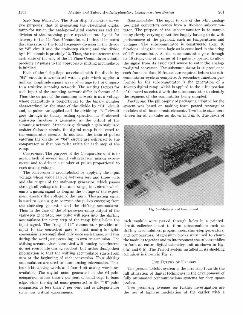
"64" circuits is associated with a gate which applies a commutator cycle is complete. A secondary function per-uniform amplitude square wave of voltage to 1 of 6 inputs formed by the subcommutator is the generation of ato a resistive summing network. The waiting factors for 16-step digital ramp, which is applied to the 4-bit portioneach input of the summing network differ in factors of 2. of the word associated with the subcommutator to identifyThus the output of the summing network is at a voltage the segment of the commutator being sampled.whose magnitude is proportional to the binary number Packaging: The philosophy of packaging adopted for thecharacterized by the state of the divide by "64" circuit system was based on making foam potted rectangularand, as pulses are applied and the divide by "64" circuit modules of all basic circuit elements. Two basic sizes weregoes through its binary scaling operation, a 64-element chosen for all modules as shown in Fig. 5. The leads ofstair-step function is generated at the output of thesumming network. After passage through a gain stabilized ~...emitter follower circuit, the digital ramp is delivered tothe comparator circuits. In addition, the train of pulsesentering the divide by "64" circuit are delivered to thecomparator so that one pulse exists for each step of theramp.
Comparator: The purpose of the Comparator unit is toaccept each of several input voltages from analog experi-ments and to deliver a number of pulses proportional toeach analog voltage.The conversion is accomplished by applying the input
voltage whose value can lie between zero and three voltsand the output of the stair-step generator, which passesthrough all voltages in the same range, to a circuit whichemnits a gatinig signal as long as the voltage of the experi-ment exceeds the voltage of the ramp. This gating signalis used to open a gate between the pulses emerging; fromthe stair-step generator and the shifting accumulator.Thus in the case of the 64-pulse-per-ramp output of the Fig. 5-Modules and breadboard.stair-step generator, one pulse will pass into the shiftingaccumulator for every step of the ramp lying below the each module were passed through holes in a printed-input signal. The "ring of 11" commutator provides an circuit collector board to form subassemblies such asinput to the controlled gate so that analog-to-digital shifting accumulators, programmers, stair-step generators,conversion is accomplished only once each frame, and this and comparators. Magnesium blocks were used to clampduring the word just preceding its own transmission. The the modules together and to interconnect the subassembliesshifting accumulators associated with analog experiments to form an entire digital telemetry unit as shown in Fig.do not recirculate during readout, but rather dump their 6(a) and 6(b). The Telebit system installed in its shieldinginformation so that the shifting accumulator starts from container is shown in Fig. 7.zero at the beginning of each conversion. Four shiftingaccumulators are used to store analog information. Thus THE FUTURE OF TELEBITfour 6-bit analog words and four 4-bit analog words are The present Telebit system is the first step towards theavailable. The digital noise generated in the 64-pulse full utilization of digital techniques in the development ofcomparison is less than 2 per cent of band edge to band fully automated communications systems for deep spaceedge, while the digital noise generated in the "16"-pulse probes.comparison is less than 7 per cent and is adequate for Two promising avenues for further investigation aresome less critical experiments. the use of biphase modulation of the carrier with a
202 IRE TRANSACTIONS ON SPACE ELECTRONICS AND TELEMl1ETRY December
Fig. 7-Telebit flight package.
the present Telebit system, the micrometeorite count isstored for a period of 6 to 10 hours and thus the resultingtransmission from the satellite to the ground provides an
average rate for a 6-hour period and then, as the experi-ment is read out again, the average rate for a 2.5minute interval. A relatively simple change in the digitalcircuit logic would permit onie to record durinig the 6-hourperiod the maximum counting rate that occurred in anyone of t-he 2.5-minute intervals, the minimum count-ing rate that occurred in any of the 2.5-minute inter-vals, the time at which these maximum and minimum ratesoccurred, in addition to the average count for the entire6-hour period. By the skillful application of such satellitedata processing, considerable increases in the amounfC ofinformation obtained from the experiments can be achievedwithout appreciably increasing the requiremenits on thetotal information channel capacity.
Finally, as data is accumulated, the experimenter will
(b) be better able to define the steps required for the anialysisFig. 6(a) and (b)-Telebit packages. of the data. At this point it will be possible to program the
central computer to accomplish the mechanical part of
resutan sinalto-niseimpoveent f aproimaelythe data analysis in addition to its normal task of data
6 db and the use of multiple bit encoding techniques which rdcin hsaiiyt prahteielo eltm
should further improve the modulation efficiency. In analysis of experimental data is perhaps the most im-
addition to these fundamental changes, it is possible, by portant single characteristic of the digital telemetrychanging the logical designt of the system, to decrease the system.weight and power requirements. Such changes in logical CONCL-SIO-Ndesign become more desirable as the quantity of infor-mation to be transmitted from future payloads increases. The utilizationi of digital techniques in the TelebitBy these means it appears possible to more closely system provides five present and potential advances inapproach the theoretical limnits on channel capacity. the art of scientific space communication. The followingAnother general area of improvement in the Telebit are increased.
system involves expanding analysis or processing of the Efficiency: Digital encoding techniques provide a
experimental data before transmission. For example, in nearly ideal modulation technique. Telebit itself is less
1959 Mueller and Taber: An Interplanetary Communication System 203
than 10-db above the Shannon limit on the required between the encoder and the decoder without loss ofenergy per bit of information. information. Noise of uniform-spectral-density is assumed
Accuracy: Digital encoding at the source is the first to be added to the signal in the channel. The decoder forgreat step towards improving transmission accuracy. each of the two systems inverts the process carried outOptimum redundant encoding will make possible virtually in the encoder. Furthermore, to make the two systemserror free transmission where channel bandwidth is avail- equivalent, it is assumed that N + 1 distinguishableable. Finally, data reduction and analysis by direct levels of information are to be transmitted. That is, withreading into and use of the digital computer will minimize a reasonable possibility of success, the data user should behuman errors in the final processing of data. able to tell which one of the N + 1 possible levels was
Flexibility: Data processing before transmission, changes transmitted.of scale and accuracy of readout, addition, subtraction, orrearrangement of experiments are all facilitated or made FM Telemetry Systemfeasible by the digital system.Seed:lbythe time rired r n a d. To avoid duplication in the derivation of certain equa-Speed:The time required for data gathering anddata
tions, this section follows the notation and uses severalreduction are greatly reduced in the Telebit system. i . FUltimately, it is possible to provide a continuous and .automatic flow of data from the experiment through the in reference, the equations which are used are summarizedentire communication network to the computer which here.collates, selects, and analyzes the experimental andposition data and presents the results in graphical or 4) S (1)tabular form.Economy: The elimination of human intervention in the =
co03 i
flow of information from experiment to its ultimate em 2 0.35radian (2)presentation with the attendant increase in data handlingcapability is a most important step on the way to the Loop Noise Bandwidth = 1.06Bo = 2B,o (3)economic utilization of the experimental data garneredfrom our unmanned space laboratories. . IN\
Loop Noise-to-Signal Ratio = 2B104) = y-S}2B10 = 0.4 (4)APPENDIX
2 0BoThe following section derives relationships showing (5)
the communication efficiency of a single-channel FMsystem using a phase-lock discriminator and a single- Eq. (1) expresses the phase-noise spectral density (4b)channel Telebit system. To arrive at these expressions, as a function of the channel-noise spectral density (4),) andcertain assumptions are required which may not necessarily the signal power (S). Eq. (2) expresses the relationshipbe equivalent in the two cases. However, the form of the between the maximum loop resonant phase error (em) andresulting expressions is correct even though the values of the maximum peak-to-peak excursion of a sine wavecertain constants may vary with the assumptions. Both (A&), having a frequency wi and the loop resonant fre-the systems can be described by the same block diagram quency B, The above-mentioned report also states thatas shown in Fig. 8. To make the systems equivalent, a 2o confidence level is obtained if the maximum transient
error is set equal to 0.35 radian and the loop signal-to-noise ratio expressed in (4) is set equal to 4 db. Eq. (3)
Source WI CF Ecd Badwidth Dscod 's tates the relationship between the loop resonant frequencyA.gular--quenly and the loop noise bandwidth. Eq. (4) is self-explanatory-trfoiSe Iand (5) expresses the relationship between the mean
Doensirty square output noise, the input noise spectral density, and=C- mthe loop resonant frequency. It should be noted that theFig. 8-Block diagram. dimension of of is radians per second which corresponds
dimensionally with the peak signal excursion Aw.If it is assumed that N + 1 levels are just distinguish-
able if each level is separated from the next adjacent levelfilter which limits its maximum frequency to a value c.In the case of the frequency modulated subcarrier, thnbe n tnaddeito fu. rltosi eweencoder consists of a voltage-controlled oscillator which A n - ilb salse.Ti eainhpitranslates the varying input voltage to a varying output A\ct = Ncrf. (6)frequency. In the case of the Telebit system, the encoderconsists of an analog-to-digital converter followed by abiphase modulator. The channel bandwidth is defined as 4 B. D. Martin, "A Coherent Minimum Power Lunar ProbeTelemetry System," Jet Propulsion Labs., Pasadena, Calif., ex-the minimum-width bandpass filter which can be inserted ternal publication No. 610; Au-gust 12, 1958.
204 IRE TRANSACTIONS ON SPACE ELECTRONICS AND TELEMETRY December
Now by combining (3), (4), and (5), the following relation- of ,B for the FM system follows closely that of a multilevelship is derived. AM system.
o7 = 0.365Bo. (7) Telebit System
Here use has been made of the fact that for a 2o- confidence The signal power required for the Telebit system canlevel, the loop signal-to-noise ratio is 4 db. be derived as follows. Using a PCM system, log 2 (N + 1)Now (6) and (7) can be combined to give binary pulses are required to convey N + 1 levels of
Aco = 0.365NBo. (8) information. And by the sampling theorem, we mustsample the incoming information at a rate equal to coi/r.
Eq. (2) can be rewritten to yield Thus (oi/ir) log, (N + 1) pulses per second must be2o= 1.43 Aco co . (9) transmitted through the channel. This requires a channelBo= 1.43,A -co- bandwidth Aco as follows.
Now solve the system of (8) and (9) to give B0 and Aw as /o = 2coi log, (N + 1). (15)functions of N and c,i.
Bo = 0.52Ncoi (10) The noise in this bandwidth is
2 (11)Ac,, = 0.I9Nc (o1) - Ic log, (N + 1).Thus, if the number of levels of the highest information The required signal is derived from the above and thefrequency are specified, the frequency deviation Aco whicheshould be used for minimum signal power when a 2 raconfidence level has been specified, is given by (11). S 1092 (N + (16)Similiarly the loop resonant frequency of the phase-lock- 7r lgloop discriminator used to demodulate this signal is given Now the signal-to-noise ratio that is required depends
by (10). -on the quality that is desired. If a 3o- confidence level isNow, to define a figure of merit for the system, we desired for each pulse, then for a biphase system S/Nmust define the information rate H. It is clear by the useof the sampling theorem that the maximum informationrate for this system is twice the highest frequency in S = 4.5 (b 1092 (N + 1). (17)cycles per second multiplied by the number of bits repre- 5 4sented by the distinguishable levels. Under the assump- Thus the figure of merit for the Telebit system is foundtions made.
to be
H = log, (N + 1). (12) 57r ~~~~~ ~~~~~~~4.5.(18)
The signal power required to convey this amount of in- This is 8-db poorer than the limit. This equation indicatesformation can be determined by the use of (1), (3), (4), that # is independent of N which is not completely true.and (10). For a more rigorous comparison, the 3o confidence level
S = 1.38I)"Nwcoi. (13) should be imposed on each group of pulses characterizingone N-bit sample taken as a whole. This imposes the
Sanders has chosen a figure of merit: which characterizes requirement that the probability of success for eachthe system efficiency and represents the signal energy individual pulse must be greater than that for the grouprequired per bit, normalized for noise spectral density. and therefore greater signal power is required. However,For this system since this increase is based on an inverse error function,
S 4.33N it is much smaller than the increase encountered in the=bCH - log, (N- + 1) (14) FM system.
By way of example, /3 has been computed for a system ACKNOWLEDGEMENTrequiring 64 levels, that is N = 63, and for a binary The Telebit system would not have been possiblesystem, that is N = 1. For these cases ,B = 45.5 and 4.33, without the creative efforts of our colleagues and par-respectively. Thus, a system requiring 64 levels is 18.2 db ticularly the work of R. E. Gottfried. The paper itselfpoorer than the ideal and the 2-level system is 8 db is due in large measure to the dauntless effort of R. A.poorer than the ideal. It should be noted that the form Park.