Page 1
An Introduction to Cooling Tower
Water Treatment
Course No: C05-019
Credit: 5 PDH
J. Paul Guyer, P.E., R.A., Fellow ASCE, Fellow AEI
Continuing Education and Development, Inc. 9 Greyridge Farm Court Stony Point, NY 10980 P: (877) 322-5800 F: (877) 322-4774
[email protected]
Page 2
© J. Paul Guyer 2014 1
J. Paul Guyer, P.E., R.A. Paul Guyer is a registered civil engineer, mechanical engineer, fire protection engineer and architect with 35 years of experience designing buildings and related infrastructure. For an additional 9 years he was a principal staff advisor to the California Legislature on capital outlay and infrastructure issues. He is a graduate of Stanford University and has held numerous national, state and local offices with the American Society of Civil Engineers, Architectural Engineering Institute and National Society of Professional Engineers.
An Introduction to
Cooling Tower
Water Treatment
Page 3
© J. Paul Guyer 2014 2
CONTENTS
1. TYPES OF COOLING WATER SYSTEMS
2. COOLING TOWER WATER CALCULATIONS
3. OBJECTIVES OF COOLING WATER TREATMENT
4. MICROBIOLOGICAL DEPOSITS AND CONTROL
5. CORROSION IN COOLING SYSTEMS
6. DEVELOPING AN EFFECTIVE COOLING WATER TREATMENT PROGRAM
7. COOLING WATER SYSTEM START-UP AND LAYUP REQUIREMENTS
(This publication is adapted from the Unified Facilities Criteria of the United States government which are in the public domain, have been authorized for unlimited distribution, and are not copyrighted.)
Page 4
© J. Paul Guyer 2014 3
1. TYPES OF OOLING WATER SYSTEMS. Cooling water systems remove heat
generated from a variety of industrial processes. There are three basic types of cooling
water systems: once-through, open recirculating, and closed recirculating cooling water
systems. This publication describes once-through and open recirculating systems.
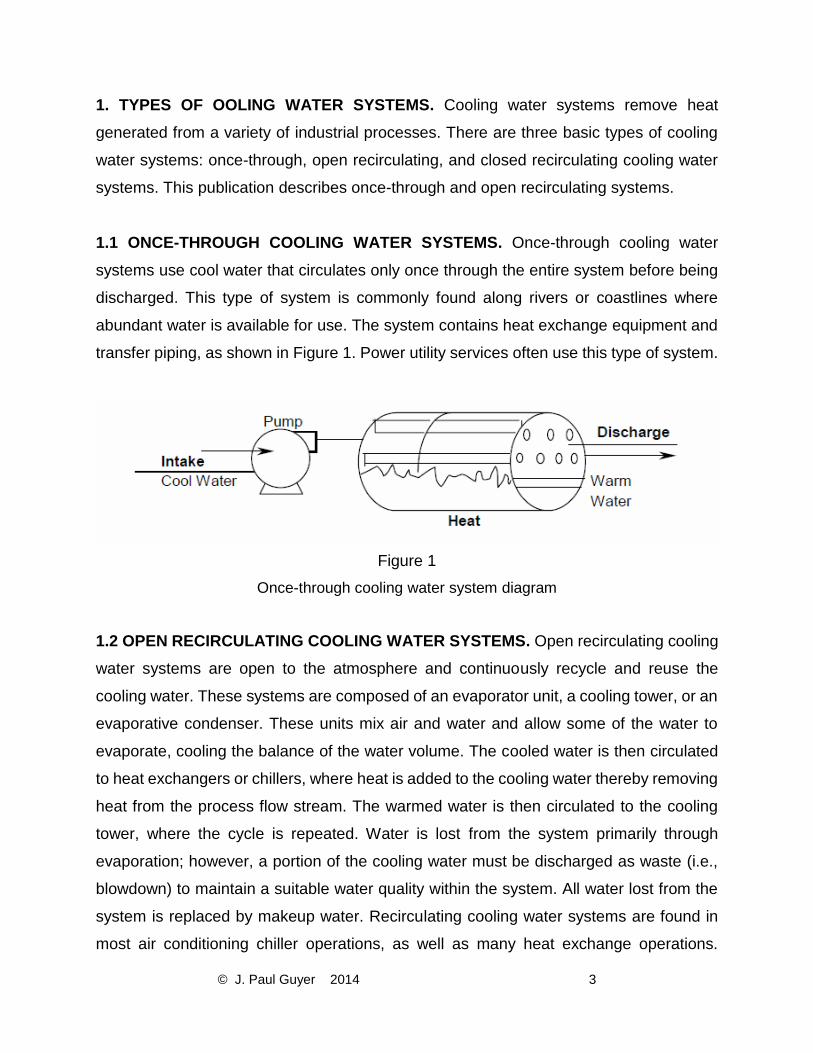
1.1 ONCE-THROUGH COOLING WATER SYSTEMS. Once-through cooling water
systems use cool water that circulates only once through the entire system before being
discharged. This type of system is commonly found along rivers or coastlines where
abundant water is available for use. The system contains heat exchange equipment and
transfer piping, as shown in Figure 1. Power utility services often use this type of system.
Figure 1
Once-through cooling water system diagram
1.2 OPEN RECIRCULATING COOLING WATER SYSTEMS. Open recirculating cooling
water systems are open to the atmosphere and continuously recycle and reuse the
cooling water. These systems are composed of an evaporator unit, a cooling tower, or an
evaporative condenser. These units mix air and water and allow some of the water to
evaporate, cooling the balance of the water volume. The cooled water is then circulated
to heat exchangers or chillers, where heat is added to the cooling water thereby removing
heat from the process flow stream. The warmed water is then circulated to the cooling
tower, where the cycle is repeated. Water is lost from the system primarily through
evaporation; however, a portion of the cooling water must be discharged as waste (i.e.,
blowdown) to maintain a suitable water quality within the system. All water lost from the
system is replaced by makeup water. Recirculating cooling water systems are found in
most air conditioning chiller operations, as well as many heat exchange operations.
Page 5
© J. Paul Guyer 2014 4
Evaporative fluid coolers and evaporative condensers are terms defining open
recirculating cooling water systems that use evaporators, which are slightly different than
a cooling tower and do not send the cooled water out of the evaporative unit itself. An
evaporative cooler cools a circulating fluid that does not change phase (e.g., does not
condense from a gas to a liquid). An evaporative condenser cools a circulating fluid from
a gas into a liquid, such as a refrigerant. The hot fluid that is to be cooled is brought to
the unit. Figure 2 shows a typical evaporative cooler and evaporative condenser diagram;
Figure 3 shows a typical open recirculating cooling water system; and Figure 4 shows a
typical cooling tower system.
Figure 2
Evaporative fluid cooler and evaporative condenser diagram
Page 6
© J. Paul Guyer 2014 5
Figure 3
Open recirculating cooling tower water system diagram
Page 7
© J. Paul Guyer 2014 6
Figure 4
Cooling tower water system
1.3 TYPES OF COOLING TOWERS. Types of cooling towers include natural draft, induced
draft, and forced draft.
1.3.1 NATURAL-DRAFT TOWERS. In natural-draft towers, airflow through the tower is
achieved naturally (i.e., without any mechanical means such as fans). Air flows across the
falling water and up through the cooling tower as a result of the differential density between
the lighter (heated and humidified) air within the tower and the cooler and dryer outside air.
Fitting the tower with spray nozzles, which create more mixing of air and water droplets and
improve the evaporation efficiency, produces increased water-cooling rates. Large utility
Page 8
© J. Paul Guyer 2014 7
power plants use these large natural-draft cooling towers which are called hyperbolic cooling
towers due to their hyperbolic shape (see Figure 5).
Figure 5
Hyperbolic natural-draft cooling towers
1.3.2 FORCED-DRAFT TOWERS. The term “forced draft” denotes that air is forced or blown
by fans into the cooling tower and up through the flow of falling water in the cooling tower.
Drift eliminators are installed to prevent water entrained in the air from leaving the system.
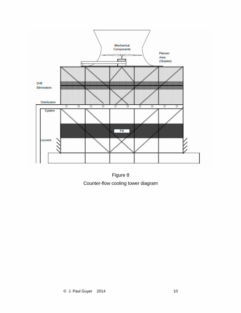
1.3.3 INDUCED-DRAFT TOWERS. The term “induced draft” denotes that air is drawn by fans
through the flow of falling water and up and out of the cooling tower. The airflow can be drawn
either cross-flow or counter-flow with respect to the orientation of the falling water, resulting
in either a cross-flow tower or a counter-flow tower. Drift eliminators are also present. (See
Figures 6, 7, 8, and 9 for diagrams and photos of cross-flow and counter-flow cooling towers.)
Page 9
© J. Paul Guyer 2014 8
Figure 6
Cross-flow cooling tower
Page 10
© J. Paul Guyer 2014 9
Figure 7
Cross-flow cooling tower
Page 11
© J. Paul Guyer 2014 10
Figure 8
Counter-flow cooling tower diagram
Page 12
© J. Paul Guyer 2014 11
Figure 9
Counter-flow cooling tower
1.3.4 TYPICAL COOLING TOWER INSTALLATIONS. Cooling towers are commonly of
the induced-draft, cross-flow variety, although counter-flow and forced-draft cooling
towers are also represented. The cooling towers range in size from small to large
capacity.
1.4 COMPONENTS OF A COOLING TOWER. Figure 10 shows a simple diagram of a 1-
fan, induced-draft, cross-flow cooling tower. The major parts of the tower include the basin
and cold well, louvers, fill, water distribution (and fan) deck, drift eliminators, fan and fan
discharge, and the endwall casings.
Page 13
© J. Paul Guyer 2014 12
Figure 10
Induced-draft cross-flow cooling tower components
1.4.1 BASIN AND COLD WELL. The basin is that portion of the cooling tower structure
located under the tower that is used for collecting cooled water and which can be used
as a location for adding makeup water. The cold well is a deepened portion of the basin
that contains submerged water circulation pumps. The basin may be constructed of
concrete, wood, metal, or fiberglass.
1.4.2 LOUVERS. Louvers are flat or corrugated members constructed of wood, plastic,
cement board, or fiberglass, and installed across (horizontally) the open side of a tower.
Page 14
© J. Paul Guyer 2014 13
The main function of louvers is to prevent water from splashing out of the cooling tower
through the openings where air enters the tower. Louvers are usually set at an angle to
the direction of airflow.
1.4.3 FILL. Fill is the internal part of a tower where air and water are mixed. The fill
intercepts the downward fall of water. The water is mixed with the air contained in the fill
material and water is evaporated and cooled. There are two types of fill: splash fill and
film fill. The falling water hits the splash fill, splashes, and breaks up into smaller water
droplets, resulting in an increased rate of evaporation. The splash fill is made of wooden
slats or bars, plastic, or ceramic tile. Film fill is a compact plastic material, similar to a
honeycomb, which causes water to flow over the fill material, creating a large wet surface
that maximizes evaporation as air travels past the film surface (see Figure 11).
Figure 11
High-efficiency cooling tower film fill
Page 15
© J. Paul Guyer 2014 14
1.4.4 DRIFT ELIMINATORS. The drift eliminators efficiently remove water droplets from
the air and return the recovered water to the cooling tower, thereby minimizing the loss
of cooling tower water. They are located in areas that are situated after the fill and water
sprays and just before the area where the air exits the cooling tower (see Figures 6 and
8). Drift eliminators are also known as “mist eliminators.”
1.4.5 WATER DISTRIBUTION AND FAN DECK. In a cross-flow cooling tower, the hot
water basin is used to distribute the warm return water flow uniformly over the tower fill
(see Figure 6). In a counter-flow cooling tower, water sprays are used to distribute the
warm water (see Figure 8). The fan deck supports the motor and fan of the water spray
system. The stack is the structure (typically a cylinder) that encloses the fan and directs
warm, humid discharge air upward and out of the cooling tower.
1.4.6 CELL. This is the smallest subdivision of a large cooling tower in which the fan can
operate as an independent unit. A midwall casing must separate each end of the cell from
the adjacent cells to ensure all air flow induced by the cell fan is drawn only through the
cell fill and mist eliminator air path. Figure 7 illustrates a typical three-cell cross-flow
cooling tower. Figure 9 illustrates a typical four-cell counter-flow cooling tower.
1.5 COMMON COOLING WATER SYSTEM PROBLEMS. Water-related problems can
cause system downtime, loss of equipment efficiency, the need for capital replacement
of equipment, and can increase the risk of disease from pathogenic microorganisms. An
open recirculating cooling tower system has a greater potential for these problems than
does a once-through cooling water system, due to the air- and water-mixing design of the
open recirculating system. These problems are associated with water-caused deposits,
corrosion, or microbiological organisms, and occur for various reasons:
• The cooling tower is essentially a huge air scrubber that can introduce materials
such as microorganisms, gases, dust, and dirt into the circulating water, which
provides an excellent growth environment for pathogenic microorganisms. These
materials can contribute to the formation of deposits and cause corrosion.
Page 16
© J. Paul Guyer 2014 15
• If the water is not properly treated and its quality maintained, corrosion, scale and
solids deposition can occur. The potential for these problems results from the
nature of the cooling system design and the operating conditions, including water
evaporation, mineral concentration, and water temperatures of up to 54 °C (130
°F).
• The constant addition of makeup water results in increased quantities of mineral
constituents that can form scale, deposits, and corrosion. Blowdown control and
proper water treatment can minimize these problems.
• The film fill contains small water and air passages that can become plugged,
thereby causing a reduction in cooling tower operational efficiency due to reduced
water evaporation (see Paragraph 1.4.3).
• Current designs for heat exchangers and cooling towers provide for more efficient
operation than in the past, but unexpected water problems may occur. Some of
the more prevalent potential problems are described in Paragraphs 1.5.1 through
1.5.4.
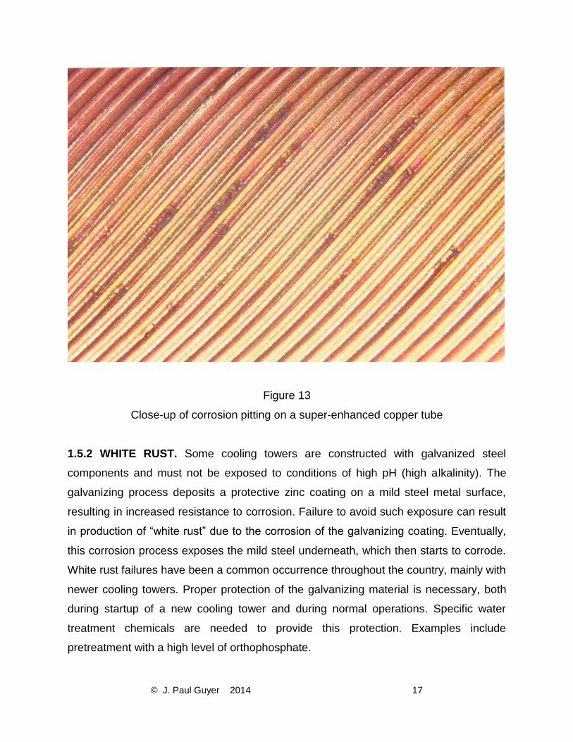
1.5.1 ENHANCED AND SUPER-ENHANCED CHILLER CONDENSER TUBING. Recent
air conditioning chiller equipment designs incorporate enhanced and super-enhanced
chiller condenser tubes. Previous designs have used smooth-bored waterside condenser
tubing. The enhanced tube is machined with rifled grooves that provide an increased
surface area and a resultant increase in heat transfer; however, the rifled grooves and
ridges tend to entrap suspended solids (i.e., dirt, silt, sand, and old corrosion products),
which are deposited from the cooling water as it passes through the tube. This deposition
of material on metal surfaces can create a type of localized corrosion called “under-
deposit corrosion.” This situation has resulted in numerous cases of tube failure. The
super-enhanced chiller tubes have even finer grooves and ridges, making this type of
tubing even more susceptible to under-deposit corrosion. (See Figures 12 and 13 which
show photos of super-enhanced copper tubes.)
Page 17
© J. Paul Guyer 2014 16
Figure 12
Super-enhanced copper tubes
Page 18
© J. Paul Guyer 2014 17
Figure 13
Close-up of corrosion pitting on a super-enhanced copper tube
1.5.2 WHITE RUST. Some cooling towers are constructed with galvanized steel
components and must not be exposed to conditions of high pH (high alkalinity). The
galvanizing process deposits a protective zinc coating on a mild steel metal surface,
resulting in increased resistance to corrosion. Failure to avoid such exposure can result
in production of “white rust” due to the corrosion of the galvanizing coating. Eventually,
this corrosion process exposes the mild steel underneath, which then starts to corrode.
White rust failures have been a common occurrence throughout the country, mainly with
newer cooling towers. Proper protection of the galvanizing material is necessary, both
during startup of a new cooling tower and during normal operations. Specific water
treatment chemicals are needed to provide this protection. Examples include
pretreatment with a high level of orthophosphate.
Page 19
© J. Paul Guyer 2014 18
1.5.3 COOLING TOWER FILM FILL. Small- and medium-sized cooling towers use film
fill, which is a tightly packed media as compared to the splash-type fill used prevalently in
the past (see Paragraph 1.4.3 and Figure 11). Film fill has a higher potential for fouling
(plugging) due to adherence and entrapment of biomass and of suspended solids (i.e.,
dirt, silt, and sand). The cooling capacity of a cooling tower can be reduced if the film fill
is extensively fouled (see Figure 14). Instances of severe fouling have resulted in the
collapse of fill into the cooling tower basin. In addition, fouling deposits in the fill can harbor
pathogenic microbiological organisms such as Legionnaires’ disease.
Figure 14
Heavily Fouled Cooling Tower Film Fill
1.5.4 LEGIONELLA BACTERIA. This type of bacteria is the cause of Legionnaires’
disease. It can grow in cooling water systems even when a proper microbiological control
program has been maintained. This bacterium can be discharged in the drift produced
Page 20
© J. Paul Guyer 2014 19
from all types of cooling tower systems. If a susceptible person inhales the bacteria, the
disease could possibly develop. Due to increased awareness by cooling tower operators
and the water treatment industry in general, the risk of being infected by Legionella
Pneumophila or other pathogenic microorganism from a cooling tower system is probably
not much greater today than it was a few years ago. Still, a number of outbreaks of
Legionnaires’ disease are reported each year throughout the country. See Paragraph
1.4.7 for more information on controlling Legionella.
Page 21
© J. Paul Guyer 2014 20
2. COOLING TOWER WATER CALCULATIONS
2.1 PRINCIPLES OF COOLING TOWER SYSTEM OPERATIONS. The function of a
cooling tower is to dissipate heat from water-cooled refrigeration, air-conditioning and
industrial process systems. Water is typically the heat transfer medium used to dissipate
the heat. A cooling tower uses a combination of heat and mass transfer (evaporation) to
cool the water flowing through the tower. Conductive heat transfer accounts for 20 to 30%
of the total heat dissipated. The remaining 70 to 80% of total cooling is the result of
evaporative cooling of about 1 to 2% of the recirculating water, depending on the
decrease in temperature across the tower. It takes approximately 2,326,000 joules to
evaporate 1 kilogram of water (1000 BTU per 1 pound of water). If this amount of heat is
extracted from 454 kilograms (1000 pounds) of water, approximately 0.45 kilogram (1
pound) of water will be evaporated and the temperature will drop 0.55 °C (1 °F). If 4.5
kilograms (10 pounds) of water are evaporated, the water temperature will drop 5.5 °C
(10 °F). The water lost by evaporation is replaced with makeup water. Water is also added
to replace water lost through tower drift (loss of water from the tower as a fine mist), leaks
in the system (unintentional blowdown), and water discharged as intentional blowdown.
Water that is added to the cooling tower to replace all of these losses is known as cooling
tower makeup water.
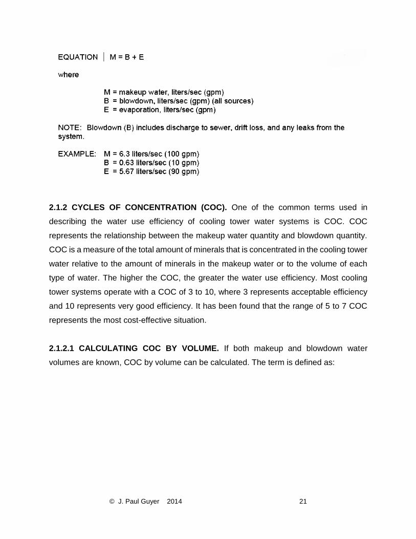
2.1.1 RELATIONSHIP BETWEEN EVAPORATION, BLOWDOWN, AND MAKEUP. The
operation of cooling towers can be described by the relationship between evaporation,
blowdown, and makeup. Makeup water must equal blowdown water plus water
evaporation to maintain a constant operating water level in the system:
Page 22
© J. Paul Guyer 2014 21
2.1.2 CYCLES OF CONCENTRATION (COC). One of the common terms used in
describing the water use efficiency of cooling tower water systems is COC. COC
represents the relationship between the makeup water quantity and blowdown quantity.
COC is a measure of the total amount of minerals that is concentrated in the cooling tower
water relative to the amount of minerals in the makeup water or to the volume of each
type of water. The higher the COC, the greater the water use efficiency. Most cooling
tower systems operate with a COC of 3 to 10, where 3 represents acceptable efficiency
and 10 represents very good efficiency. It has been found that the range of 5 to 7 COC
represents the most cost-effective situation.
2.1.2.1 CALCULATING COC BY VOLUME. If both makeup and blowdown water
volumes are known, COC by volume can be calculated. The term is defined as:
Page 23
© J. Paul Guyer 2014 22
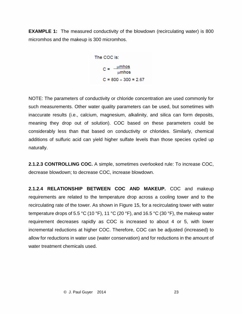
2.1.2.2 DETERMINING COC BY WATER ANALYSES. To determine COC, you must
know the mineral content of both makeup and blowdown water. For example, you must
determine both the conductivity of the recirculating cooling tower water and the
conductivity of the makeup water. (Note that the blowdown water will have the same
conductivity as the recirculating water.) Conductivity is commonly measured in
micromhos (μmhos). You can also estimate COC by using other water quality parameters
such as chlorides, silica, or sulfates. The relationship is represented by this equation:
Page 24
© J. Paul Guyer 2014 23
EXAMPLE 1: The measured conductivity of the blowdown (recirculating water) is 800
micromhos and the makeup is 300 micromhos.
NOTE: The parameters of conductivity or chloride concentration are used commonly for
such measurements. Other water quality parameters can be used, but sometimes with
inaccurate results (i.e., calcium, magnesium, alkalinity, and silica can form deposits,
meaning they drop out of solution). COC based on these parameters could be
considerably less than that based on conductivity or chlorides. Similarly, chemical
additions of sulfuric acid can yield higher sulfate levels than those species cycled up
naturally.
2.1.2.3 CONTROLLING COC. A simple, sometimes overlooked rule: To increase COC,
decrease blowdown; to decrease COC, increase blowdown.
2.1.2.4 RELATIONSHIP BETWEEN COC AND MAKEUP. COC and makeup
requirements are related to the temperature drop across a cooling tower and to the
recirculating rate of the tower. As shown in Figure 15, for a recirculating tower with water
temperature drops of 5.5 °C (10 °F), 11 °C (20 °F), and 16.5 °C (30 °F), the makeup water
requirement decreases rapidly as COC is increased to about 4 or 5, with lower
incremental reductions at higher COC. Therefore, COC can be adjusted (increased) to
allow for reductions in water use (water conservation) and for reductions in the amount of
water treatment chemicals used.
Page 25
© J. Paul Guyer 2014 24
Figure 15
Effect of COC on makeup requirement
2.1.3 RELATIONSHIP BETWEEN BLOWDOWN, EVAPORATION, AND COC. You can
use the cooling water evaporation loss to calculate the blowdown rate that must be
maintained to operate at a selected COC. The relationship between blowdown,
evaporation, and COC is represented with this equation:
Page 26
© J. Paul Guyer 2014 25
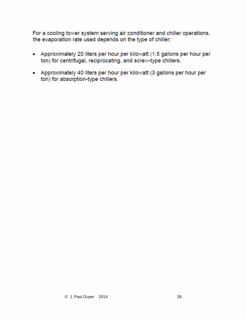
EXAMPLE 3: A cooling system operates at 315 liters per second (5000 gallons per
minute). The temperature drop through the tower is 7.8 °C (14 °F). The evaporation
estimate is represented by this equation:
Page 27
© J. Paul Guyer 2014 26
Page 28
© J. Paul Guyer 2014 27
3. OBJECTIVES OF COOLING WATER TREATMENT. The primary objectives of
cooling water treatment are to maintain the operating efficiency of the cooling water
system and to protect the equipment that contacts the cooling water. These objectives
are accomplished by controlling or minimizing deposition, corrosion, and microbiological
growth on the cooling water equipment. Treatment programs must also address
requirements for environmental compliance, safety, water conservation, and limitation of
chemical costs. This paragraph reviews the requirements for, and elements of, a water
treatment program for cooling water systems.
3.1 DEPOSIT FORMATION AND CONTROL. Deposits that occur in cooling water
systems are usually divided into two categories: scale and fouling. The presence of either
type of deposit in the heat exchangers or in the film fill can interfere with heat transfer,
thereby reducing the efficiency of operation. Deposits can also promote under-deposit
corrosion. Scale and non-biological fouling are described in this paragraph. Biological
fouling is described in Paragraph 3.4.
3.2 SCALE. Scale is formed from minerals, formerly dissolved in water, which were
deposited from the water onto heat transfer surfaces or in-flow water lines. As water is
evaporated in a cooling tower, the concentration of dissolved solids becomes greater until
the solubility of a particular scale-causing mineral salt is exceeded. When this situation
occurs in an untreated cooling water system, the scale will form on any surface in contact
with the water, especially on heat transfer surfaces. The most common scaling minerals
are calcium carbonate, calcium phosphate, calcium sulfate, and silica; usually in that
order. Formation of magnesium silicate scale is also possible under certain conditions.
Most other salts, including silica, are more soluble in hot water than in cold water;
however, most calcium and magnesium salts, including calcium phosphate and calcium
carbonate, are more soluble in cold water than in hot water. This is called “reverse
solubility.” The water temperature will increase as recirculating water passes through the
cooling system. As a result, calcium and magnesium scales may form anywhere in the
system, but most likely on heated surfaces such as heat exchangers or surface
Page 29
© J. Paul Guyer 2014 28
condensers. Silica will form in areas having the lowest water temperature, such as in the
cooling tower fill.
3.2.1 DETERMINING SCALING POTENTIAL. The maximum solubility limit for specific
dissolved minerals will determine the types of scale that can form under a given set of
conditions. To minimize water blowdown, the amount of dissolved materials in the cooling
water should be maintained as close as possible to the maximum solubility level. This
water quality parameter, total dissolved solids (TDS), is controlled by maintaining COC in
the system at a level that is equal to the lowest COC allowable for whichever salt has the
lowest solubility. The salt of concern is often calcium carbonate or calcium phosphate,
but it may be silica. The operating COC can be increased substantially with the use of the
cooling water treatment chemicals described in this paragraph.
3.2.2 CALCIUM CARBONATE SCALE. Calcium carbonate scale results from the
breakdown of calcium bicarbonate, a naturally occurring salt. The degree of scaling
depends primarily on the calcium levels, bicarbonate alkalinity levels, and water
temperature in the cooling water system. The most accurate prediction of scale can be
developed using the Practical (Puckorius) Scaling Index (PSI) (see Paragraph 3.4.2). A
rough prediction of calcium carbonate scale potential can be developed using this
formula:
Page 30
© J. Paul Guyer 2014 29
3.2.3 CALCIUM PHOSPHATE SCALE. Calcium phosphate scale results when calcium
hardness reacts with phosphate. This will occur when more than 10 ppm of
orthophosphate are present in the circulating water and when the calcium hardness is
sufficiently high. The following formula can provide a very rough prediction of the potential
for calcium phosphate scale:
3.2.4 CALCIUM SULFATE SCALE. Calcium sulfate scale results when the calcium
hardness reacts with the sulfate. The potential for calcium sulfate scale can be predicted
using this formula:
3.2.5 SILICA SCALE. Silica scale can occur when the concentration of silica exceeds its
maximum solubility limit in water. A safe, very conservative value to assume for the
solubility limit is 150 ppm (as SiO2); thus, the maximum COC can be calculated with this
formula. However, silica solubility depends on pH and temperature and is in the range of
Page 31
© J. Paul Guyer 2014 30
approximately 150 to 180 ppm (as SiO2) at the temperature range encountered in most
cooling towers (26 °C to 54 °C [80 °F to 130 °F]). As the pH increases in the cooling tower
water, silica becomes more soluble; thus, if cooling tower water pH is 9.0, approximately
250 ppm silica (as SiO2) is the maximum. Using 150 ppm as the upper limit, the allowable
COC is represented by this equation:
3.3 DETERMINING COC TO CONTROL OPERATIONS. In cooling water systems, the
lowest calculated COC allowable, as determined by the relationships for these salts, is
the controlling factor for operations. This is because as the system operates, the material
that has the lowest calculated COC will be the first to come out of solution (precipitate)
and the most likely to form a scale deposit in the system. To prevent these materials from
forming a deposit on cooling water equipment, you must keep the COC in the system at
a level that is lower than the lowest COC calculated for calcium carbonate, calcium
phosphate, calcium sulfate, and silica. Using appropriate water treatment chemicals will
allow higher COC, depending on which chemical is used.
Page 32
© J. Paul Guyer 2014 31
EXAMPLE 4:
At what COC can the system operate scale free without water treatment? (Assume that
the estimated pH in the blowdown water is 8.5.)
The COC determined for calcium carbonate is lowest at 4.3, and this controls the system
operation. If the system is operated without water treatment, scaling should not occur if
the system is operated at less than 4.3 COC. Use of scale control treatment will allow the
number of allowable COC (for calcium carbonate) to be increased; you can then
determine the COC and blowdown by using a calculated scaling index.
Page 33
© J. Paul Guyer 2014 32
3.4 CALCIUM CARBONATE SCALING INDICES. The scale found most commonly in
cooling tower water systems is calcium carbonate, present in the form of calcite (CaCO3)
(i.e., limestone). The solubility of calcium carbonate, which decreases with an increase in
temperature, is a complex function of temperature, TDS, calcium hardness, total
alkalinity, and pH. To predict if scale would form in the hotter sections of a cooling water
system, researchers have developed several scaling indices. Paragraphs 3.4.1 and 3.4.2
describe the predictive indexes that are used most commonly for cooling water.
3.4.1 LANGELIER AND RYZNAR INDICES. W.F. Langelier derived a method to
calculate the calcium carbonate scale-forming and scale-dissolving tendencies of drinking
water. The method is based on determining the saturation pH (pHs) at which calcium
carbonate scale will start to precipitate out of solution. If the measured pH (pHactual) of
the water is greater than its pHs, thus a positive value, the water has a scale-forming
tendency. If the measured pH (pHactual) of the water is less than its pHs, thus a negative
value, the water will have a scale-dissolving tendency. The pHactual minus pHs is known
as the Langelier Index or Langelier Saturation Index (LSI) (LSI = pHactual – pHs). This
index was originally designed to predict calcium carbonate scale in potable water. There
are serious deficiencies in the accuracy of this index; consequently, it has lost its practical
application for cooling water systems. J.W. Ryznar later devised a more sensitive formula
for predicting calcium carbonate scale. This formula is known as the Ryznar Index or
Ryznar Stability Index (RSI). The formula is: 2pHs − pHactual. A value of 6 indicates
“stable” water, a value less than 6 indicates a scale-forming tendency, and a value greater
than 6 indicates a scale-dissolving tendency. The indices have also been used to try to
estimate the degree to which calcium carbonate scale will form in drinking water and in
cooling water. The more positive the LSI value, the greater the scale formation; however,
for the RSI, the smaller the index, the greater the scale formation. The LSI and RSI can
give conflicting predictions based on the same water quality information.
3.4.2 PRACTICAL (PUCKORIUS) SCALING INDEX (PSI). Paul R. Puckorius and J.
Maxey Brooke developed a modified version of the RSI that gives a more accurate and
consistent indication of the calcium carbonate scaling potential of cooling water. Known
Page 34
© J. Paul Guyer 2014 33
as the Practical Scaling Index (PSI), and also known as the Puckorius Scaling Index, it
takes into consideration the effect of the type of total alkalinity of the cooling water on the
measured pH (pHactual) value. The measured pH does not always relate correctly to
bicarbonate alkalinity because of the buffering effect of other ions. Rather than using the
measured pH in calculating the PSI, an adjusted or equilibrium pH (pHeq) is used: PSI =
2pHs - pHeq. As with the RSI, a PSI value of 6 indicates stable water and a value lower
than 6 indicates a scale-forming tendency. Without scale-control treatment, a cooling
tower with a PSI of 6 to 7 should operate scale free. However, a PSI of greater than 6
indicates that scaling may occur. Information on calculating the PSI is provided in
Appendix B. Use of the PSI is most applicable when cooling water pH is above 7.5.
3.5 SCALE-CONTROL METHODS. Three basic methods are used to prevent the
formation of scale in cooling water systems:
a) Remove the water scaling ingredients from the water before use. This includes
softening, RO, and other technologies.
b) Keep the scale-forming ingredients in solution. This is the most common scale-control
method used for cooling water, and it can be achieved by the use of either or both of the
following two methods: adding acid, which lowers the pH of the recirculating water, or
adding a scale inhibitor (phosphonate or specific polymer), which allows higher COC to
be maintained without scaling. Acid neutralizes (destroys) mineral alkalinity, one of the
constituents forming calcium carbonate scale; however, because of the hazards
associated with handling strong acids and the potential damage from an acid spill, the
use of acid in cooling towers is not recommended.
c) Allow the water-scaling ingredient to precipitate as sludge. Modern chemical treatment
can distort or modify scale crystals such that they cannot adhere to each other to form a
hard deposit; instead, they become a sludge that can be removed through filtration or
blowdown.
Page 35
© J. Paul Guyer 2014 34
All three methods are authorized for use on military installations and can be used in
combination with one another.
3.5.1 CALCIUM CARBONATE SCALE CONTROL USING SOLUBILIZING
CHEMICALS. Acids and phosphonates are chemicals that keep scale from forming. The
use of acid in cooling towers may not be appropriate for use at military installations due
to the associated risk of corrosion.
3.5.1.1 ACIDS. The acid most commonly used is sulfuric acid used as a diluted solution
(e.g., 40% sulfuric acid in water). The use of acids requires adequate pH control.
3.5.1.2 PHOSPHONATES. The phosphonates used most frequently for calcium
carbonate scale control in recirculating cooling water systems are AMP (amino-tri
[methylene] phosphonic acid); HEDP (1-hydroxyethylidene 1,1-diphosphonic acid); and
PBTC (2-phosphonobutane-1,2,4-tricarboxylic acid). The chemical reaction of all
phosphonates is similar; however, their stability varies greatly. The presence of chlorine
or other oxidants in treated cooling water favors the use of PBTC, which is very resistant
to decomposition, followed by HEDP, and finally AMP. An active dosage of 3 to 5 ppm of
either AMP or HEDP, or 1.5 to 2.5 ppm PBTC, will increase the solubility of calcium
carbonate by a factor of 3 or more relative to using no chemical treatment. Rather than
operating at a PSI of 6.0 (stable water, no scale) in an untreated system, the cooling tower
water can be used at a PSI of 4.0 without the occurrence of scale (see Paragraph 3.4.2);
however, in the absence of calcium scaling conditions, phosphonates can increase the
corrosion of both mild steel and copper.
3.5.2 CALCIUM CARBONATE SCALE CONTROL USING SOLUBILIZING
POLYMERS. Many different polymers are used in water treatment. For the most part,
they have multi-faceted performance capability; they can inhibit various types of scale
formation as well as disperse SS. Often water treatment products will include more than
one type of polymer in the product formulation. For control of calcium carbonate,
homopolymers such as polyacrylate, polymethacrylate, and polymaleate are used to keep
Page 36
© J. Paul Guyer 2014 35
calcium carbonate in solution. Dosages of 3 to 5 ppm of active polymer in the cooling
tower water can control calcium carbonate scale formation to a PSI value as low as 4.5.
3.5.3 CALCIUM CARBONATE SCALE CONTROL USING SLUDGE-FORMING
POLYMERS. Certain homopolymers and copolymers act as crystal modifiers by distorting
calcium carbonate crystals such that they do not attach themselves to heat exchange
surfaces, but instead the crystals become SS that can be removed through filtration or
blowdown. Usually dosages of 1 to 3 ppm of active polymer in the cooling tower water will
control calcium carbonate scale. Due to formation of sludge, rather than the stabilization
of carbonate in solution, the PSI is not meaningful under these conditions.
3.5.4 CALCIUM PHOSPHATE SCALE CONTROL USING SOLUBILIZING
INHIBITORS. Often calcium phosphate scale is formed in cooling water systems treated
with a phosphate-based corrosion inhibitor program or when phosphate is present in the
makeup water (i.e., potable or recycled water). Calcium phosphate is much less soluble
in water than is calcium carbonate. If the calcium hardness is 500 ppm and the pH is
above 7.0, without any polymer treatment calcium phosphate scale will likely form, even
at the low level of 10 ppm phosphate (as PO4) in the cooling water (see Paragraph 3.3).
Calcium phosphate solubility can be increased by a factor of a little less than 3 by the
addition of 4-ppm phosphonate (HEDP/PBTC) or by the use of 6 to 8 ppm of a copolymer
or terpolymer specific for calcium phosphate inhibition.
3.5.5 CALCIUM SULFATE SCALE CONTROL USING SOLUBILIZING POLYMERS.
Calcium sulfate formation can result from high concentrations of calcium ions and sulfate
ions in the recirculating water; however, calcium sulfate is the most soluble of the scale-
forming calcium salts found in cooling tower waters having pH levels of greater than 8.0.
This means that calcium sulfate scale will not form unless some calcium ions (hardness)
remain in solution after the calcium reacts with all the carbonate and phosphate in the
water. Calcium sulfate scale may occur when the recirculating water contains calcium
hardness in the range of 500 to 700 ppm as CaCO3 and sulfate in the range of 500 to 700
ppm SO4. (See the predictive index in Paragraph 3.4) The addition of 3 to 5 ppm of a
Page 37
© J. Paul Guyer 2014 36
copolymer of acrylate and acrylamide will allow calcium sulfate to remain in solution at a
level almost 3 times the level allowed when using no treatment. Calcium sulfate scale
rarely forms at pH levels above 8.0 in the cooling water.
3.5.6 MAGNESIUM SILICATE SCALE CONTROL. Formation of magnesium silicate is
possible in cooling systems, but only under certain rare conditions. Magnesium ions
(hardness) first react with hydroxyl ions (OH-) to form magnesium hydroxide, which then
reacts with (absorbs) dissolved or colloidal silica. A deposit analysis often reports this
material as magnesium silicate. Since magnesium hydroxide solubility decreases at pH
levels above 9.0, this scale will usually occur only at a pH level above 9.0 and when the
magnesium hardness concentration is greater than 100 ppm.
3.5.7 SILICA SCALE CONTROL. Silica solubility is dependent upon temperature and
pH. At pH levels greater than 8.5, silica remains soluble (no scale) at a concentration of
250 ppm as SiO2. At pH levels of 7.5 or below, maximum silica solubility is 150 ppm as
SiO2. At maximum silica levels, silica will first deposit on the cooling tower slats rather
than in the heat exchanger because silica is more soluble in hot water than in cold water.
The slats will become coated with a white, sometimes sparkling, deposit. If this occurs,
blowdown should be increased to decrease COC by at least 1 unit. This procedure should
stop additional scale formation. If the concentration of silica in the makeup water is above
30 ppm, it will usually be the parameter that controls the adjustment of cooling water
system COC. If the silica concentration is high, external treatment can reduce the level of
silica in the makeup water. The introduction of water treatment chemicals based on new
polymer technology may allow the solubility of silica to be increased above the old
recognized limit of 150 ppm.
Table 1 summarizes the scale control methods.
Page 38
© J. Paul Guyer 2014 37
Table 1
Summary of Scale Control Methods
3.6 COOLING WATER FOULING. The term “fouling” refers to the deposition of materials
that are normally held in suspension in the cooling water: mud, silt, and other SS brought
into the system with the makeup water; dust, dirt, and debris scrubbed out of the air
passing through the tower; product leakage such as oils; corrosion products from the
system; and biological organisms, both living and dead. Combinations of any or all of
these materials can be present in the cooling water.
3.7 FOULING CONTROL. Fouling from mud, dirt, and corrosion products can be
controlled by the addition of a water-soluble polymer dispersant, such as a polyacrylate.
The addition of about 4 to 5 ppm of active polymer, together with sufficient water velocity
(e.g., 1 meter per second [3.28 feet per second]), can keep foulants in suspension and
prevent them from being deposited on heat transfer surfaces. Higher dosages (5 to 20
ppm) of active polymer can be required for heavily fouled systems. It is best to reduce the
loading of SS by mechanically removing them from the system through blowdown,
filtration, and physical sump cleaning. Removing oil or oily materials requires a non-
Page 39
© J. Paul Guyer 2014 38
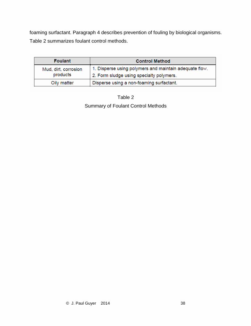
foaming surfactant. Paragraph 4 describes prevention of fouling by biological organisms.
Table 2 summarizes foulant control methods.
Table 2
Summary of Foulant Control Methods
Page 40
© J. Paul Guyer 2014 39
4. MICROBIOLOGICAL DEPOSITS AND CONTROL. Microbiological organisms are
composed of three classes: algae, bacteria, and fungus. Large biological organisms such
as clams, snails, mussels, or similar species are referred to as macrobiological
organisms. The presence of any biological growth can be detrimental to cooling tower
operations. Problems include fouling, corrosion, and loss of efficiency. These problems
can lead to downtime, higher operating cost, and even premature replacement of
equipment. Additionally, some bacteria are pathogenic and can pose a risk to human life.
4.1 ALGAE. The term “algae” refers to algal, microbiological, tiny, stringy blue and blue-
green plants, which are usually found growing in masses on top of and on sides of cooling
towers. Algae grow only in sunlit areas. They will slough off and become part of the
suspended matter in the circulating water, a situation which may cause fouling and
plugging of water sprays. Algae also provide a breeding place, and are a nutrient, for
bacteria.
4.2 BACTERIA. The term “bacteria” refers to a large group of one-celled microorganisms.
Bacteria can grow in either the absence or presence of sunlight. There are several ways
to classify bacteria, including “aerobic,” meaning those living in the presence of oxygen,
and “anaerobic,” meaning those living in the absence of oxygen. In a cooling water
system, one can categorize bacteria as either “planktonic” or “sessile,” which are terms
that describe whether the bacteria are, respectively, either free floating or found growing
on surfaces (stickers). Categories of bacteria are described below. Table 3 shows types
of bacteria and their growth conditions.
4.2.1 PLANKTONIC BACTERIA. Planktonic bacteria are suspended in the water,
sometimes referred to as “free floaters” or “swimmers,” and are aerobic bacteria that
thrive in an oxygenated environment. They are not harmful to the cooling system since
they do not cause deposits or corrosion, but they can provide nutrients for other
microorganisms; in addition, some planktonic bacteria such as Legionella Pneumophila
are pathogenic and can present a significant human health risk.
Page 41
© J. Paul Guyer 2014 40
4.2.2 SESSILE BACTERIA. Sessile bacteria are stickers, or non-swimming bacteria, and
can cause deposits and corrosion. Sessile bacteria types include slime-formers and
anaerobic (corrosive) bacteria. Slime-formers can grow and form gelatinous deposits on
almost any surface in contact with the cooling water. These deposits can grow so large
that they restrict water flow and interfere with heat transfer; they also may promote under-
deposit corrosion. Feeling the sides of the cooling tower basin just below the water level
is one way to detect the presence of slime-formers. Usually if there are slime formers in
the system, you can feel deposits. Anaerobic bacteria thrive in oxygen-deprived
environments and often establish colonies beneath slime deposits or under other types
of deposits. One type of anaerobe is sulfate-reducing bacteria (SRB), which produce
hydrogen sulfide, a chemical that is very corrosive to metals. This type of corrosion attack
is very localized and can result in pipe and tube failures. The presence of SRB should be
suspected in a water system if the underside of a slime layer is black or if you detect the
odor of rotten eggs. Any type of microbiological corrosion is referred to as
microbiologically influenced corrosion (MIC). Bacteria cause most of the MIC found in
cooling water systems. Use surface microbiological measurements to monitor sessile
bacteria.
Page 42
© J. Paul Guyer 2014 41
Table 3
Bacterial types and problems created
Page 43
© J. Paul Guyer 2014 42
4.3 FUNGI. The term “fungi” refers to classes of organisms made up of molds and yeasts,
some of which attack and cause wood decay in cooling towers. The control of fungi
requires special preservative treatment of wood. Fungi also produce deposits in cooling
water equipment.
4.4 MICROBIOLOGICAL CONTROL. The term “microbiological control” refers to
techniques used to minimize the presence of microbiological organisms in cooling water.
Chemical biocide treatment is the method used on government installations for
microbiological control in cooling water. Biocides that are used to control microbiological
growth fall into one of two broad categories: oxidizing and non-oxidizing microbiocides. A
cost-effective approach for control involves the regular use of oxidizers as a primary
biocide, augmented by selective use of non-oxidizing biocides. Important factors for the
effectiveness of any biocide include using a proper dosage and allowing adequate contact
time with the microbiological organisms. All microbiocides are toxic and must be handled
safely and with caution; use the MSDS for safety instructions.
4.4.1 OXIDIZING BIOCIDES. “Oxidizing biocides” is a term describing microbiocides that
oxidize or irreversibly “burn up” the bio-organisms. Oxidizing biocides also destroy
nutrients that the microorganisms require for growth. Avoid addition of excess amounts
(over-feeding) of oxidizing biocides because they are corrosive to metal and wood in the
cooling system and have the potential to destroy some scale and corrosion inhibitors. The
various oxidizing biocides are described below. Table 4 provides guidelines for selecting
oxidizing microbiocides.
Page 44
© J. Paul Guyer 2014 43
Table 4
Guidelines for oxidizing microbiocide effectiveness
Page 45
© J. Paul Guyer 2014 44
4.4.1.1 CHLORINE AND CHLORINE RELEASE AGENTS. Chlorine (Cl2) compounds
are the most effective industrial oxidizing biocides and the most widely used. Chlorine is
available as a chlorine gas, dry calcium hypochlorite (HTH), liquid sodium hypochlorite
(bleach), plus several other dry products that release chlorine. When chlorine is
introduced into water, it hydrolyzes to form hypochlorite ion (OCl-) and hypochlorous acid
(HOCl); it is the latter chemical that is the stronger oxidizing biocide. The presence of
hypochlorous acid is greater, proportionate to hypochlorite ion, at low pH levels. At a pH
of 5.0, hypochlorous acid exists almost exclusively. At a pH of 7.5, there are
approximately equal amounts of hypochlorous acid and hypochlorite ion. Figure 16 shows
this relationship. Chlorine is effective, but to a lesser degree, as a biocide at a pH of 7.5
or greater because the hypochlorite ion has about one-tenth the biocidal efficacy of
hypochlorous acid. A pH range of 6.5 to 7.5 is considered optimal for chlorine or chlorine-
based microbiological control programs. Above pH 7.5, relatively higher levels of chlorine
are required to be effective. Military installations seldom use gaseous chlorine for treating
cooling towers because of safety concerns, difficulty with controlling the feed of the gas,
and increasing concern for the environmental effects of escaping residual chlorine gas.
The most commonly used chlorine-based products are bleach and HTH.
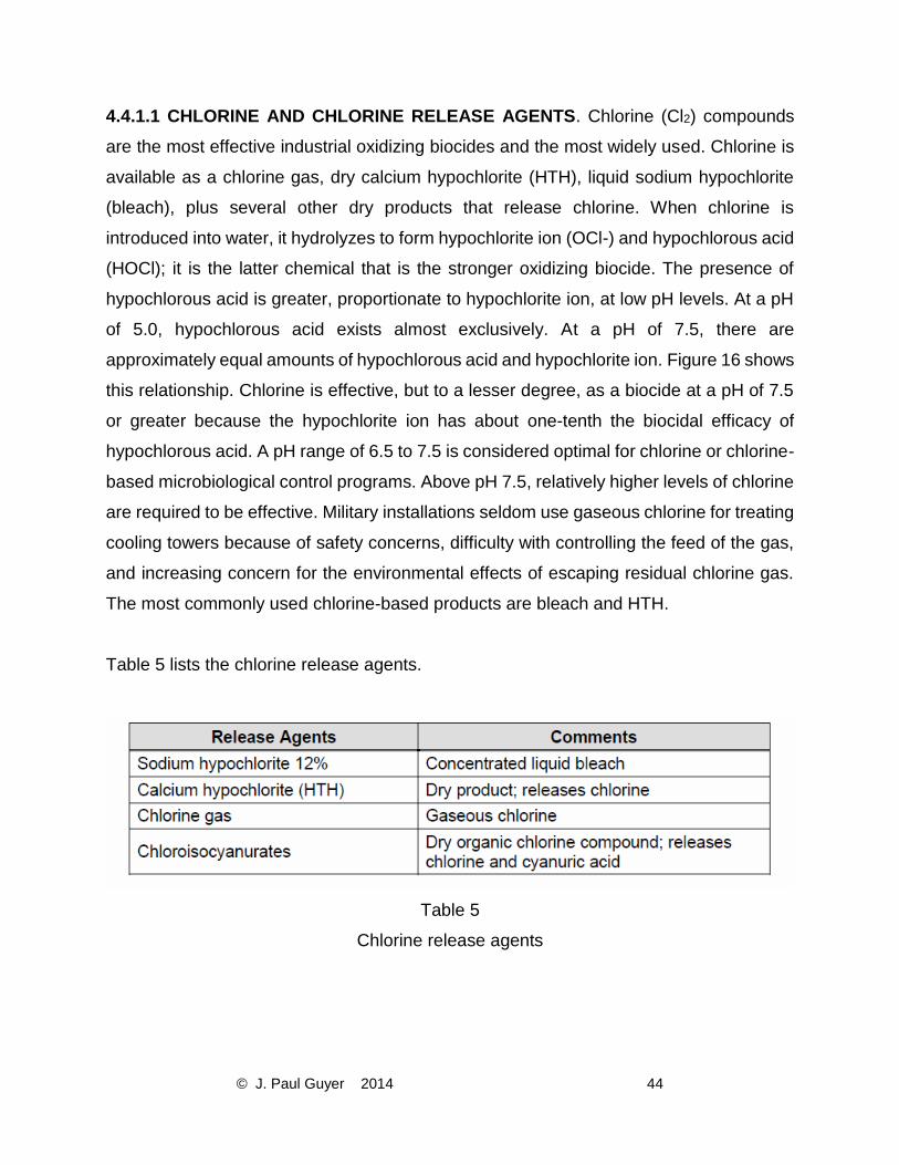
Table 5 lists the chlorine release agents.
Table 5
Chlorine release agents
Page 46
© J. Paul Guyer 2014 45
Figure 16
Halogen species vs. pH in water
4.4.1.2 Bromine Release Agents. Bromine (Br2) compounds are very similar to
chlorine compounds. Although more expensive than chlorine compounds, their main
advantage is that bromine is more effective at higher pH ranges (7.5 or greater) than
chlorine. Bromine has a lower vapor pressure than chlorine and is 6 times as soluble in
water, making it less subject to vaporization loss from a cooling tower. When bromine is
introduced to water, it hydrolyzes to form hypobromite ion (OBr-) and hypobromous acid
(HOBr); Figure 16 shows this relationship. A pH range of 7.5 to 10.0 is considered
optimal for the use of bromine. Bromine release agents include dry chemicals called
hydantoins and bromine salts, such as sodium bromide. When a salt solution is mixed
with an oxidizing agent, such as bleach, and a reaction occurs, bromine is produced. In
water, bromine degrades more rapidly than chlorine. Recent developments in bromine
chemistry have resulted in the production of a bromine solution (liquid). Table 6 shows
examples of some bromine
Page 47
© J. Paul Guyer 2014 46
release agents. The most popular sources of bromine are the dry bromine release
products.
Table 6
Bromine Release Agents
4.4.1.3 OZONE. Ozone (O3) is a gas produced by passing dry air either through a strong
electric field or near an ultraviolet light. If ozone is dissolved in water, the resulting solution
can be added to cooling water. Ozone is a very strong oxidizing biocide that, if properly
applied, can provide effective control of microorganisms in cooling tower systems.
However, because of safety and operational problems associated with its manufacture
and use, and the resulting high capital and operating costs, it is neither the most
economical method nor the preferred method for microbiological control in cooling towers
under normal operations. Ozone can increase metal corrosion and does not prevent
scale.
4.4.1.4 CHLORINE DIOXIDE. Chlorine dioxide (ClO2) is a gas generated by mixing
several chemicals. The chlorine dioxide gas produced in this manner is subsequently
dissolved in water, with the water containing the chlorine dioxide then added to the cooling
water. Chlorine dioxide must be produced in close proximity to the point of use. It is not
recommended for use on some installations due to the complexity of its production and
safety concerns associated with its production and handling.
Page 48
© J. Paul Guyer 2014 47
4.4.1.5 HYDROGEN PEROXIDE. Hydrogen peroxide (H2O2) is a liquid that is usually
used at a concentration of 30% in water. Hydrogen peroxide is considered one of the
most environmentally friendly oxidizing biocides because it degrades to water; however,
concentrated hydrogen peroxide will react in a violent manner when it comes into contact
with organic chemicals and materials.
4.4.2 NON-OXIDIZING BIOCIDES. Non-oxidizing biocides are microbiocides that act as
“poisons;” they disrupt the metabolic or reproductive processes of micro- and macro-
organisms and are therefore toxic. Non-oxidizing biocides are organic compounds that
are very toxic to organisms, including human beings and animals. They are usually
liquids, but some are available as dry products (e.g., pellets, solids). A major
consideration for their use is their persistence with respect to the discharge limitations for
water (effluent) containing these toxic substances. Also, when choosing and applying a
non-oxidizing biocide, you must consider the cooling tower system’s operating
parameters, such as pH and retention time. The applied dosages of microbiocides should
never exceed EPA maximum limits, which are always printed on the container labels. The
labels will also identify the active microbiocide ingredient, the percentage of each
chemical that is present in the formulation, and the EPA registration number. Control
programs often combine both oxidizing and non-oxidizing biocides. The most important
aspect of bio-fouling control is to match the non-oxidizing biocide to the problem
organism. Table 7 provides guidelines for non-oxidizing biocide effectiveness.
Page 49
© J. Paul Guyer 2014 48
Table 7
Guidelines for non-oxidizing microbiocide selection
Page 50
© J. Paul Guyer 2014 49
4.5 ALGAE CONTROL. Algae can be controlled by two techniques: chemical methods
and physical methods. Since algae require sunlight to survive and grow, covering the
upper hot water decks of cooling towers with plywood can often control algae deposits.
Chemical methods consist of using oxidizing and non-oxidizing biocides which can control
algae to various degrees (see Tables 4 and 7). The effectiveness of oxidizers is
considered only fair while that of several non-oxidizers is in the range of very good to
excellent. One of the more effective biocides for algae is terbutylazine, a triazine product
(see Table 7).
4.6 BACTERIAL CONTROL. Accepted industry practice for bacterial control is the use
of oxidizing and non-oxidizing biocides that are specific for the type of bacteria. The most
cost-effective microbiocide programs for medium and large cooling towers use an oxidizer
as a primary biocide and one or more non-oxidizers selectively as a secondary biocide
(see Tables 4 and 7). Smaller cooling systems often use one or more non-oxidizing
biocides, although dry oxidizing biocides are also used commonly. The most overlooked
aspect of bacterial control is maintaining a system kept clean of deposits and SS (i.e.,
dirt, silt, sand, corrosion products) through the use of filters and periodic wash-down
procedures. Clean systems reduce the demand for chemical and microbiological control.
Table 8 shows accepted industry guidelines for a bacterial control program with the use
of a test kit.
Table 8
Guidelines for bacterial control in cooling towers
4.6.1 BACTERIAL CONTROL WITH OXIDIZING BIOCIDES. Bacterial control with
oxidizing biocides can be accomplished by either continuous feed or slug feed of the
oxidant. A continuous-feed process typically maintains 0.1 to 0.3 ppm of free halogen in
Page 51
© J. Paul Guyer 2014 50
the return water to the cooling tower. A typical slug-feed process adds treatment
chemicals periodically to give 0.5 to 1.0 ppm of free halogen in the return water to the
cooling tower for a period of 2 to 4 hours, 3 times per week. Halogen refers to the group
of elements including chlorine and bromine. “Free” halogen refers to the measured
residual of halogen available for disinfection. Stabilized Halogen technology is generally
controlled on a total halogen residual. For continuous feed, control at 0.5 to 1 ppm total,
and for slug feed control at 2.4 ppm for a period 2-4 hours, 3 times per week.
4.6.2 BACTERIAL CONTROL WITH NON-OXIDIZING BIOCIDES. Bacterial control with
non-oxidizing biocides uses one or more biocides as shown in Table 7. Usually different
non-oxidizers are added on an alternating schedule; they are slug-fed every other week
for optimum effectiveness. Each time you use a non-oxidizing biocide, it is important to
maintain an adequate dosage for 24 hours to enable sufficient contact time for maximum
effectiveness.
4.7 LEGIONNAIRES’ DISEASE. Legionnaires’Disease (Legionellosis) is a respiratory
disease (atypical pneumonia) that is caused by infection of susceptible individuals who
have inhaled a fine water mist containing the bacterium known as Legionella
Pneumophila. Water in a cooling tower can become infected with the bacterium if an
inadequate microbiological control situation occurs. The presence and density of
Legionella Pneumophila bacteria cannot be detected by standard microbiological testing
methodologies. Instead, cooling water samples must be sent to a laboratory that has been
certified to conduct the required tests. If the presence of the bacteria in cooling water is
established, proper disinfection steps are required. A procedure known as the Wisconsin
Protocol, developed by the Wisconsin State Health Department, has proven effective.
This protocol requires the addition of high dosages of chlorine (10 ppm free residual) at
a pH of less than 7.5 for 24 hours, flushing the system, then repeating. Additional testing
for Legionella is required to determine the effectiveness of the procedure. Maintaining a
clean, microbiologically free cooling water system and using effective water treatment is
preferable to dealing with remedial efforts. The Cooling Technology Institute (CTI) and
the American Society of Heating, Refrigerating, and Air Conditioning Engineers
Page 52
© J. Paul Guyer 2014 51
(ASHRAE) have published position papers on the prevention of Legionella; these can be
downloaded from their respective websites: www.cti.org and www.ashrae.org.
4.8 MACROBIOLOGICAL CONTROL. The term “macrobiological control” refers to
control of larger biological organisms such as mussels, clams, and snails. They can exist
in cooling systems that use seawater or river water as makeup. The first line of defense
is using mechanical prevention with strainers and filters on the intake water to prevent
infiltration into the cooling water system. Control methods within the cooling system
include thermal shock and chemical treatment with oxidizing and non-oxidizing biocides.
Page 53
© J. Paul Guyer 2014 52
5. CORROSION IN COOLING SYSTEMS. The term “corrosion” (in a cooling water
system) is defined as the electrochemical deterioration of a metal that is in contact with
cooling water. Corrosion occurs when an electric current flows from one part of the metal
(anode) through the water (electrolyte) to another part of the metal (cathode). Corrosion
takes place at the anode only. The cathode is the driving force of the corrosion action.
Forms of corrosion associated with industrial water systems are illustrated in Figure 17.
Figure 17
Forms of corrosion
5.1 GALVANIC CORROSION. See Figure 17 (A). This term refers to corrosion that
occurs when two different metals are coupled together. The metal with the least
resistance becomes the anode and will corrode due to the electrochemical reaction
produced. One of the most common instances of galvanic corrosion occurring in cooling
water systems results when mild steel and copper alloy metals are brought into contact
with one another (e.g., copper tubing attached to a mild steel tube sheet or brass valves
connected to mild steel or galvanized piping). As a result of the electrochemical reaction,
Page 54
© J. Paul Guyer 2014 53
the copper is dissolved in the water and corrosion of copper alloy results. The copper can
also plate out (stick) on mild steel surfaces, setting up additional galvanic cells. Another
example is the electrochemical reaction that occurs when mild steel and zinc (galvanizing)
are coupled together at temperatures normally found in cooling tower systems. The zinc
becomes the anode and is corroded. Figure 18 shows the galvanic series. Any coupling
of a metal that is higher in the galvanic series with a metal or alloy that is lower in the
galvanic series results in an electrochemical reaction in which the “higher” metal functions
as the anode or active metal.
5.2 GENERAL CORROSION. See Figure 17 (D). The term “general corrosion” refers to
uniform corrosion of metal surfaces. A single piece of metal will have cathodic and anodic
areas due to differences in impurities and stresses. These areas will change periodically,
causing the metal to corrode over the entire surface at a more or less uniform rate.
5.3 CONCENTRATION CELL CORROSION. When two pieces of the same metal are in
a solution capable of acting as an electrolyte, and the electrolyte contains different
substances or the same substance in different amounts, such as a salt or a mixture of
salts, or oxygen, an electrical potential difference will develop between them.
5.3.1 CREVICE CORROSION. See Figure 17 (B). The term “crevice corrosion” refers to
corrosion that occurs in a slight separation between two pieces of metal, such as at the
contact point of two mild or stainless steel plates that have been bolted together. Water
flow is restricted in a crevice and, as a result, oxygen is consumed faster than it can be
replenished. The metal in the crevice functions as an anode and corrodes. This is a form
of concentration cell corrosion, also called “differential oxygen cell” corrosion. Stainless
steel is particularly susceptible to this type of corrosion, which results in localized or pitting
attack.
Page 55
© J. Paul Guyer 2014 54
Figure 18
Galvanic series of common metals and alloys found in cooling water systems
Page 56
© J. Paul Guyer 2014 55
5.3.2 UNDER-DEPOSIT CORROSION. See Figure 17 (C). The term “under-deposit
corrosion” refers to corrosion occurring under any type of deposit. The underside of a
deposit that has been caused by fouling, bacterial slime, or debris acts in much the same
way as the inside of a crevice. The metal under the deposit becomes anodic and corrodes.
This process is considered another form of concentration cell corrosion because oxygen
cannot easily get under the deposit. All metals are susceptible to this type of corrosion,
which results in localized or pitting attack.
5.3.2.1 MICROBIOLOGICALLY INFLUENCED CORROSION (MIC). See Figure 17 (E).
This term refers to metal corrosion associated with microbiological organisms whose
presence contributes to the creation of, or maintenance of, a corrosive environment. MIC
can be either eliminated or prevented to a large degree by the proper use of biocides.
5.4 CORROSION RATE. The term “corrosion rate” refers to the rate at which the
corrosion action proceeds. The rate is measured in units of mils per year (mpy). A mil is
0.0254 millimeter (one-thousandth of an inch). The rate measurement is performed using
corrosion coupons that have been exposed to cooling water for a short period of time (i.e.,
30 to 90 days). The weight of the coupon is measured before and after exposure to the
water. The thickness of the metal lost due to corrosion over the testing period is then
calculated using a measurement of the weight loss. This weight loss is extrapolated to
give a rate for 1 year and a calculation of the thickness loss is then performed and the
value is reported. Alternatively, this measurement can be taken using specialized
instruments that rapidly measure corrosion rates. Table 9 shows the corrosion rates for
corrosion coupons of different metals.
Page 57
© J. Paul Guyer 2014 56
Table 9
Assessing Corrosion Rates in Cooling Water Systems: 90-Day Corrosion Coupon Test
5.5 CORROSION CONTROL METHODS. In cooling water systems, two basic techniques
are used to provide corrosion protection to the metals that the water contacts: use of
chemical corrosion inhibitors and raising the pH of the cooling water. Figure 19 illustrates
the effect of pH on the corrosion rate of mild steel. Many cooling water systems contain
components fabricated primarily of copper alloy and mild steel. Galvanized steel is
present in galvanized cooling towers and stainless steel may be present in piping. As the
cooling water pH is increased (ideally to within the range of 8.0 to 9.5), copper and mild
steel corrosion rates will decrease as shown in Figure 19, although very high pH levels
Page 58
© J. Paul Guyer 2014 57
are corrosive to copper. The increase in pH alone cannot always protect metals
adequately, especially since cooling water is highly aerated (oxygen saturated). Chemical
corrosion inhibitors are used to provide protection from corrosion of the metal components
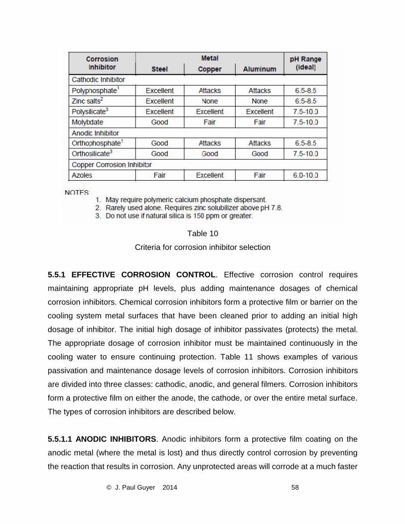
of cooling water systems. Table 10 shows criteria for the selection of corrosion inhibitors.
The principal strategy for a cooling system corrosion protection program is to ensure
protection of the metal in the heat exchanger (that is the thinnest metal in the system).
The secondary goal is to provide protection from corrosion of the mild steel piping. When
galvanized steel cooling towers are part of the cooling system, specialized corrosion
inhibitors are the best control method. Galvanized steel is corroded at pH levels above
9.0 and below 6.0.
Figure 19
Effect of pH on corrosion rate of unprotected mild steel in water
Page 59
© J. Paul Guyer 2014 58
Table 10
Criteria for corrosion inhibitor selection
5.5.1 EFFECTIVE CORROSION CONTROL. Effective corrosion control requires
maintaining appropriate pH levels, plus adding maintenance dosages of chemical
corrosion inhibitors. Chemical corrosion inhibitors form a protective film or barrier on the
cooling system metal surfaces that have been cleaned prior to adding an initial high
dosage of inhibitor. The initial high dosage of inhibitor passivates (protects) the metal.
The appropriate dosage of corrosion inhibitor must be maintained continuously in the
cooling water to ensure continuing protection. Table 11 shows examples of various
passivation and maintenance dosage levels of corrosion inhibitors. Corrosion inhibitors
are divided into three classes: cathodic, anodic, and general filmers. Corrosion inhibitors
form a protective film on either the anode, the cathode, or over the entire metal surface.
The types of corrosion inhibitors are described below.
5.5.1.1 ANODIC INHIBITORS. Anodic inhibitors form a protective film coating on the
anodic metal (where the metal is lost) and thus directly control corrosion by preventing
the reaction that results in corrosion. Any unprotected areas will corrode at a much faster
Page 60
© J. Paul Guyer 2014 59
rate than the protected areas, a factor that could result in pitting or localized attack of the
unprotected areas. Examples of anodic inhibitors include orthophosphate, nitrite, and
orthosilicates. Under certain conditions, molybdate can function as an anodic inhibitor.
5.5.1.2 CATHODIC INHIBITORS. Cathodic inhibitors form a protective film coating of the
cathodic metal (where metal is not lost) and thus indirectly prevent corrosion by interfering
with the current flow required for the electrochemical reaction to proceed between the
cathodic and anodic metals. The corrosion reaction rate is governed by the size and type
of the cathode relative to the anode. Even when cathodic areas are not completely
covered by the protective film, corrosion will occur, but usually more slowly and uniformly
than when using anodic inhibitors alone. The occurrence of localized corrosion or pitting
attack is greatly reduced. Examples of cathodic inhibitors include zinc salts,
polyphosphates, and polysilicates. Under most conditions, molybdate will function as a
cathodic inhibitor.
5.5.1.3 GENERAL INHIBITORS. General inhibitors produce a protective film on the
surfaces of all metals. These corrosion inhibitors are organic compounds, such as certain
phosphonates, amines, and other nitrogen chemicals. They may be used in cooling water
systems.
5.5.1.4 CORROSION INHIBITORS FOR SPECIFIC METALS. Some corrosion inhibitors
provide corrosion control for specific metals. The protection of copper and copper alloys
requires the use of azoles, such as tolyltriazole (TTA), benzotriazole (BZT), and
butylbenzo-thiazole, which can be added to the system separately from, or as part of a
blend of, other treatment chemicals.
5.5.1.5 GALVANIC OR CREVICE CORROSION. Control of galvanic or crevice corrosion
is achieved primarily by engineering and mechanical design. These types of corrosion
can also be partially controlled by physical and chemical considerations. A dielectric
coupling (insulator), used to separate two different metallurgies, can help prevent galvanic
Page 61
© J. Paul Guyer 2014 60
corrosion. From a chemical perspective, adjusting the pH and using proper corrosion
inhibitors will reduce corrosion.
5.5.1.6 DEPOSIT CORROSION. Control of deposit corrosion requires maintaining
deposit-free metal surfaces. This applies to any form of deposit, such as scale, biomass,
corrosion products, or foulants. The occurrence of most types of deposits is prevented by
dispersants, scale inhibitors, or biocides, along with the maintenance of adequate flow
velocities. Routine, adequate cleaning of filters and tower sumps will help reduce
deposits.
5.5.1.7 MIC. MIC is best prevented by stopping conditions that foster biological growth
and by using an effective microbiological control program. A MIC prevention program
includes adequate control (prevention) of deposits and fouling, avoidance of low-flow and
dead-leg conditions, and implementation of a consistently effective microbiological
program.
Table 11
Guidelines for Passivation Film Formation and Subsequent Maintenance
Page 62
© J. Paul Guyer 2014 61
6. DEVELOPING AN EFFECTIVE COOLING WATER TREATMENT PROGRAM. An
effective and complete cooling water treatment program addresses many factors,
including those associated with compliance and safety, protection of equipment, and cost.
Compliance and safety considerations are mandatory components of the program.
Achieving or exceeding minimally acceptable equipment protection at the lowest possible
cost is an advisable outcome for a well-designed program. The overall cost of the
treatment program includes not only the cost of chemical treatment, but also the costs of
water, disposal, manpower, and equipment. Development of an appropriate cooling water
treatment program is dependent upon knowledge of both the specific equipment to be
protected and the quality of the water to be used (source water and system water).
6.1 EQUIPMENT. Corrosion inhibitors are selected based on the metallurgy of individual
pieces of cooling system equipment. Typical systems include equipment components of
different metals. For example, systems may include smooth and enhanced copper tube
bundles, mild steel transfer piping, and galvanized cooling tower components; therefore,
to select the proper corrosion inhibitor, it is important to identify all metals contacted by
the cooling water. (See Table 10 for corrosion inhibitor selection criteria.)
6.2 OPERATIONAL FEATURES AND PARAMETERS. Operational features and
parameters of the cooling water system must be known to select the proper scale and
deposit inhibitors. This requirement refers to operational parameters such as maximum
temperature, minimum velocities, usage patterns, and whether or not layup periods occur.
The best chemical treatment programs cannot overcome the stresses of poorly operated
systems. A good example of system stress is intermittent chiller operation that allows for
SS accumulation (deposits) in chiller tube surfaces due to low flow or lack of flow. This
situation creates a strong potential for under-deposit corrosion and for MIC that the
chemical treatment may not be able to overcome completely. Stagnant water can also
cause deposits and corrosion. High water temperatures can cause scale. The maximum
water temperature should be known so that the proper scale-control method can be used.
Page 63
© J. Paul Guyer 2014 62
6.3 WATER QUALITY. Water quality within the cooling water system is a critical
consideration. The source may be potable or reuse or recycled water. The various water
constituents must be known so appropriate water treatment chemicals can be selected
for controlling specific water quality parameters.
6.4 COOLING WATER TREATMENT PROGRAMS
6.4.1 CATEGORIES. For the purpose of developing a water treatment program, cooling
tower recirculating water systems can be divided into three basic categories:
Small-sized towers – capacity less than 88 kilowatts (25 tons)
Medium-sized towers – 88 to 352 kilowatts (25 to 100 tons)
Large-sized towers – greater than 352 kilowatts (100 tons)
The water treatment program selected for cooling tower systems will vary depending on
the size of the tower (among other factors). Treatment program considerations are
described in Paragraphs 6.5 and 6.6 for small-, medium-, and large-sized towers,
respectively.
6.4.2 CYCLES OF CONCENTRATION (COC). The COC of small, medium, and large
cooling towers may be controlled by blowdown, either automatic or manual, to avoid the
high levels of silica and calcium salts that can lead to scale. If the cooling tower is not
chemically treated, the COC should be adjusted to be slightly less than the lowest
allowable COC value based on all scale-forming water ingredients. The use of chemical
treatment permits a higher COC, which is usually limited by either the chemical
effectiveness or the water treatment control.
EXAMPLE 5: An untreated cooling tower system can operate at 10 COC based on the
level of silica without scale forming, but can operate at only 2 COC based on the level of
calcium carbonate. Accordingly, the tower system should be operated at a maximum of
Page 64
© J. Paul Guyer 2014 63
2 COC. The system can likely be operated at 5 to 6 COC when an effective chemical
treatment is applied and maintained to control calcium carbonate.
6.5 TREATMENT PROGRAM FOR SMALL COOLING TOWERS. Typically a small
cooling tower will have a rating of less than 88 kilowatts (25 tons). The treatment program
used for small towers should be designed to be simple to control and easy to apply, with
very little operator attention required. This does not mean that no attention is required,
only less than that required for medium-sized systems. The treatment program for small
systems is shown in Table 12.
Table 12
Small Cooling Tower Treatment Program
6.5.1 TREATMENT. Small systems can be treated with a low dosage (5 to 10 ppm) of a
slowly soluble phosphate chemical (sodium/calcium polyphosphate) by placing a nylon
mesh bag containing the product into the cooling tower. The product, if applied in this
manner, will usually provide adequate scale and corrosion control. Microbiological control
can be obtained by the use of a dry, pelletized, oxidizing biocide, such as bromo-
chlorohydantoin or isocyanuric acid plus sodium bromide (see Paragraph 4-4.4.1). Either
of these biocides can be fed continuously via a feeder or suspended in a mesh bag in the
cooling tower water. The cooling tower sump should be kept clean of SS and other debris
by the use of a filter and periodic washdowns.
6.5.2 TESTING. Testing is usually limited to assurance that the optimum COC value is
being maintained and that the chemical treatment agents are present in the water. The
bag with the chemical treatment should not be allowed to become less than one-half full.
Page 65
© J. Paul Guyer 2014 64
The frequency for refilling the bag will vary; once every 1 to 2 months is typical. Initially,
the treatment level should be checked to assure that adequate, but not excessive, levels
of both phosphate and the biocide are present in the cooling water.
6.6 TREATMENT PROGRAM FOR MEDIUM AND LARGE COOLING TOWERS. The
chemical treatment program for these cooling tower systems (typically greater than 88
kilowatts [25 tons]) requires sufficient, regular testing as well as water and chemical
control to protect the equipment in contact with the cooling water. Usually treatment
includes control of scale, fouling, microbiological growth, and corrosion. The composition
of an optimum chemical treatment program for cooling towers on a military installation
depends on the quality of the water available, the operating conditions of the cooling
system, and the environmental constraints placed on treatment chemicals in the
blowdown water (effluent discharge limitations). Conditions at a particular installation may
require variation of the quantity or mix of the chemicals suggested in Table 13.
6.6.1 TREATMENT. Medium and large cooling towers are usually, but not always, treated
with a liquid formulation containing both scale inhibitors and corrosion inhibitors. These
are often simply referred to as an "inhibitor.” Inhibitor products are usually fed on a
continuous basis using automated control and feed equipment. The concentration of
these formulated products varies greatly from vendor to vendor. Biocides are usually, but
not always, liquid products. It is common to use an oxidizing biocide as a primary biocide
and a non-oxidizing biocide as a secondary biocide, as needed, to control bacteria and
other biological growth. Oxidizing biocides can either be fed continuously at a low level
or dosed periodically at a higher level. Non-oxidizers are dosed as needed and only when
oxidizing biocides are either ineffective or not used at all.
Page 66
© J. Paul Guyer 2014 65
Table 13
Treatment programs for medium and large cooling towers
6.6.2 TESTING. Testing should be done regularly to insure that COC, chemical levels,
and bacteria levels are within the targeted control range. This requirement could demand
a testing frequency of three times per week, or even daily.
6.7 COOLING TOWER OPERATOR DUTIES. If detected early, problems associated with
scaling, corrosion and fouling in a cooling tower system can be minimized by corrective
action. Some of the things the operator should look for when on-site are described below.
6.7.1 COOLING TOWER DISTRIBUTION DECK. It is important to look for the presence
of algae, debris, or anything that has plugged water distribution holes causing an uneven
water flow through the tower, thus lowering tower efficiency. Clean plugged holes and
replace damaged water distribution spray nozzles.
Page 67
© J. Paul Guyer 2014 66
In addition, look for the presence of algae deposits. If algae deposits are present, increase
the level or frequency of biocide or algaecide treatment, and cover the deck if uncovered.
6.7.2 COOLING TOWER FILL, AIR INTAKE SLATS, AND BASIN
6.7.2.1 SCALE DEPOSITS ON COOLING TOWER FILL. The presence of deposits,
particularly on cooling tower fill, can be established by removing some fill to determine if
partial plugging has occurred. Scale can range in color from white to gray or reddish
depending on the scale composition. Scale formation on the cooling tower fill usually
indicates a severe scaling situation. If possible, obtain a sample of the scale for analysis
and, based on the result, select a scale inhibitor for that specific scale.
6.7.2.2 SCALE DEPOSITS ON AIR INTAKE SLATS. Scale can form on the air intake
slats of a cooling tower. This buildup is due mostly to water splashing and evaporating,
causing deposition of soluble salts or minerals. This situation does not indicate a serious
problem. These deposits can be, and should be, washed off periodically, but ideally not
into the cooling tower basin. Chemical treatment can provide some reduction in the
occurrence deposits.
6.7.2.3 SLIME DEPOSITS. Slime deposits (microbiological) can sometimes be detected
by feeling below the water level on the distribution deck and on the walls of the cooling
tower basin. Most microbiological growth will have a slimy feel. If slime deposits are
present, increase biocide frequency or increase the dosage.
6.7.2.4 SUSPENDED SOLIDS. The purpose of a dispersant is to keep particulate solids
in suspension and to prevent them from settling or from adhering to heat transfer surfaces.
Adequate water flow is required to prevent them from settling. Particulate solids in
suspension are removed with the blowdown water. The tower water should be turbid if
the dispersant is doing its job. Keep the cooling tower sump clean of SS by cleaning
periodically and using a filter.
Page 68
© J. Paul Guyer 2014 67
6.7.3 CORROSION TEST COUPONS. When removing corrosion coupons, always note
and record the visual appearance with regard to the presence of scale, rust, or biomass.
Take photographs of the corrosion coupons. Submit (or evaluate) coupons for corrosion
rate and for the type of corrosion that is occurring.
6.7.4 INSIDE SURFACE OF HEAT EXCHANGER TUBES. To effectively examine the
inside (water-contacted) surfaces of heat exchanger tubes, a boroscope is needed
because only a few inches of the interior can be seen visually using a flashlight. Scale
deposits, typically hard and tightly adhered to the tube surface, range in color from white
to gray or reddish depending on the composition of the scale. No scale should be present.
It is important to inspect heat exchanger tubes at least once per year. Fouling-type
deposits may look similar to scale deposits. Unlike scale, these deposits usually adhere
loosely to the tube surface. Biomass will appear slimy and feel slippery, and they will
usually adhere loosely.
6.7.5 CHILLER PERFORMANCE. Degradation of chiller performance or chiller efficiency
may be a strong indication of scale or fouling problems in the chiller. If a reduction in
chiller capacity occurs while cooling water is being cooled efficiently and within design
parameters, then the chiller condenser section should be opened and examined. The
chiller evaporator section may not contain water material scale but may be fouled with
corrosion products. You should open and examine the chiller evaporator if chilled water
could possibly be inadequately treated.
6.7.6 COOLING TOWER SURFACES. Cooling towers made of galvanized steel should
be examined for white rust or possible rusty surfaces that may indicate that the
galvanizing is no longer present on the metal surfaces and the steel is rusting. Cooling
towers constructed of wood should be examined for wood deterioration or decay.
Page 69
© J. Paul Guyer 2014 68
7. COOLING WATER SYSTEM START-UP AND LAYUP REQUIREMENTS. The startup
of a new cooling water system requires special consideration. Proper cooling water
system layup is also important, especially for chiller tube bundles or other heat exchange
equipment. For a new cooling tower system, it is important to make sure that the
equipment that contacts the cooling water is clean and properly protected from initial
corrosion. Also, disinfection is needed to eliminate the presence of microbiological
organisms that can cause corrosion, deposits, and growth of pathogenic organisms such
as Legionella bacteria. Implementation of a proper layup process is critical to prevent
corrosion and microbiological growth during stagnant water conditions.
7.1 STAND-BY CONDITIONS. The term “stand-by” is often applied to a chiller that is in
rotation with other chillers on-line. This stand-by period could be of varying duration, from
a few days to a few weeks. Rotating chillers frequently is important for minimizing
stagnant conditions that lead to under-deposit and MIC corrosion. It is a good practice to
run the recirculation pumps through a stand-by chiller for at least 15 minutes each day to
minimize corrosion. A chiller that must be left on stand-by for an extended period of weeks
without recirculation should be laid up wet or dry according to procedures described in
Paragraph 7.4.
7.2 COMMON PROBLEMS DURING LAYUP OR DUE TO IMPROPER INITIAL START-
UP. Common problems that occur during layup or due to improper initial start-up include
corrosion of tubes and transfer piping (sometimes to the point of failure), micro-biological
growth with potential for MIC corrosion, and growth of pathogenic microorganisms.
7.3 START-UP OF NEW COOLING WATER TOWER SYSTEMS
7.3.1 INITIAL CLEANING. A new cooling water tower system will contain dirt, oils, greasy
films, and rust located on the metal surfaces as a result of system fabrication. A pre-
operational alkaline cleaning process is required to remove the dirt, oil, grease, and rust,
and to prepare metal surfaces for initial corrosion control. When galvanized steel is
involved, special care must be taken so that the pH does not exceed 8.5 during the
Page 70
© J. Paul Guyer 2014 69
cleaning and passivation process to avoid conditions that promote white rust. The
cleaning and passivating procedure for a new cooling tower system is usually part of a
new system construction project and, as such, is not in the direct control of the cooling
system operations personnel. Verification of the completion of these important steps is
obtained from the contracting officer involved with the project. A cleaning and passivation
procedure for cooling tower systems with galvanized steel is provided below. The
procedure is similar for systems that do not contain galvanized steel, except that the pH
restriction does not apply.
7.3.2 CLEANING AND PASSIVATION PROCEDURES. In the startup of new cooling
tower systems containing complex metallurgies that include galvanized steel, follow the
cleaning and passivation procedures for cooling tower systems containing galvanized
steel, stainless steel, mild steel, or copper. These procedures should not be used for
cleaning and passivating aluminum. Conventional chemical cleaners and typical heating,
ventilation, and air conditioning (HVAC) water treatment programs use highly alkaline,
high-pH water, which can initiate white rust formation on galvanized surfaces and copper
tubes. Galvanized steel can simply be passivated by exposure to highly aerated water
and a phosphate or polysilicate treatment. This treatment forms a zinc corrosion inhibition
layer which is a natural, dense, adherent, and protective corrosion product film. High pH
(above 8.5) produces unwanted white rust that is fragile and not protective against
corrosion. The following procedures are recommended.
7.3.2.1 HYDROSTATIC TESTING. PERFORM HYDROSTATIC TESTING:
a) Inspect and remove all debris.
b) Fill the system with treated water and circulate. This should include orthophosphate or
hexametaphosphate (as PO4) at 40 to 60 ppm, and tolyltriazole (active) at 10 to 20 ppm.
7.3.2.2 PRE-OPERATIONAL CLEANING PROCEDURE. If the system passes
hydrostatic testing, proceed immediately to this pre-operational cleaning and passivation
procedure. Do not allow untreated water to be added to the system.
Page 71
© J. Paul Guyer 2014 70
a) Drain and flush any debris from hydrostatic testing.
b) Dose and circulate (for 24 hours) a sufficient amount of a cleaning formula based on
the volume of the system. A formulation is provided below.
c) Drain and flush the system, and clean all strainers.
d) Fill the system with makeup water and circulate for 30 minutes.
e) Take a sample of system water while it is circulating. The sample should match the
makeup water supply for clarity and SS; conductivity ±10%; and pH ±0.3 pH units from
7.5 to 8.5.
If necessary, repeat steps (a) through (e) until the system water matches this description.
The system should now be clean and passivated.
7.3.2.3 CHEMICAL CLEANING AND PASSIVATION FORMULATION. Apply this
chemical cleaning and passivation formulation when the water system pH is 7.5 to 8.5;
adjust pH as required. Formulation limitations may require adding separate components
to keep things in solution. Other formulations may be used.
• Orthophosphate (or) hexametaphosphate (as PO4): 60 ppm
• Polyacrylate (active): 20 ppm
• Tolyltriazole (active): 10 ppm
• Sodium gluconate: 50 ppm
• Pluronic L-61 (active) (non-ionic surfactant with antifoam): 400 ppm
• Phosphate scale inhibitor: 50 ppm
7.3.2.4 PASSIVATION OF THE SYSTEM. Supplemental corrosion inhibitors may be
used in conjunction with the phosphate but are not required. Maintain and circulate the
levels for the time required. After passivation, proceed to operational readiness or layup
as required. Tables 14 and 15 show chemical technology used for passivation.
7.3.2.5 OPERATIONAL READINESS. If system operation is not required for a period of
a week or more, proceed to layup. For normal operation, allow corrosion inhibitor levels
Page 72
© J. Paul Guyer 2014 71
to subside to maintenance levels through normal blowdown. Proceed to the maintenance
water treatment program.
Table 14
Required Chemical Technology
Table 15
Supplemental Chemical Technology
7.4 LAYUP OF COOLING TOWER SYSTEMS
7.4.1 WET LAYUP OF COOLING WATER SYSTEMS AND EQUIPMENT. Systems and
system equipment such as heat exchangers, chiller tube bundles and the like can be laid
up wet, but first they require a physical cleaning to remove all the suspended materials.
Apply corrosion inhibitors at increased dosages, usually at a level of about 4 to 5 times
the normal maintenance dosage. Apply an increased dosage (within EPA limits) of a non-
oxidizing biocide that has a long half-life, such as glutaraldehyde or isothiazolone.
7.4.2 DRY LAYUP OF COOLING WATER SYSTEMS AND EQUIPMENT. Systems and
equipment can be laid up dry, although dry layup is more appropriate for a single piece
of equipment such as a chiller’s condenser tube bundle or other heat exchanger. All metal
surfaces must be completely dry; residual moisture is not acceptable. In humid climates
Page 73
© J. Paul Guyer 2014 72
you should use a desiccant such as a quicklime gel or an equivalent. Place the desiccant
in as many locations as necessary and replace as required.