An Approved Continuing Education Provider PDHonline Course C659 (2 PDH) An Introduction to Geotextiles in Erosion Control J. Paul Guyer, P.E., R.A. 2013 PDH Online | PDH Center 5272 Meadow Estates Drive Fairfax, VA 22030-6658 Phone & Fax: 703-988-0088 www.PDHonline.org www.PDHcenter.com
(This publication is adapted from the Unified Facilities Criteria of the United States government which are in the public domain, have been authorized for unlimited distribution and are not copyrighted.) (Figures, tables and equations in this publication are at times at times a little difficult to read, but they are the best available. DO NOT PURCHASE THIS PUBLICATION IF THIS LIMITATION IS UNACCEPTABLE TO YOU.)
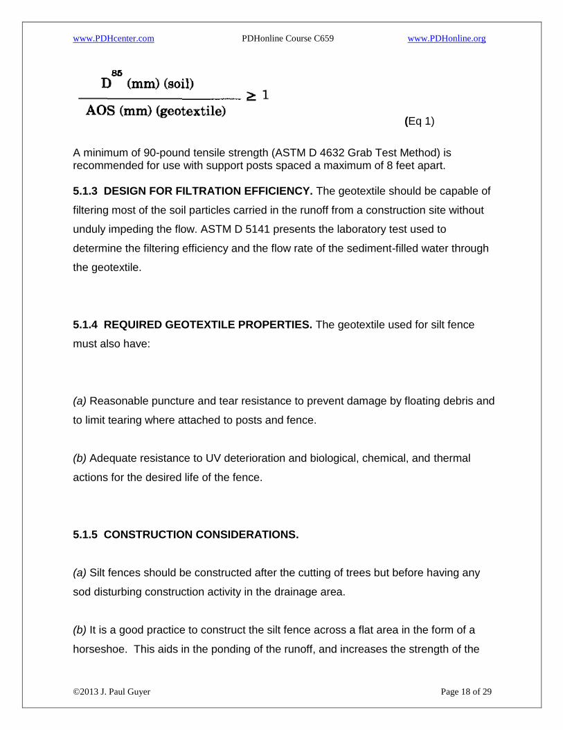
A minimum of 90-pound tensile strength (ASTM D 4632 Grab Test Method) is recommended for use with support posts spaced a maximum of 8 feet apart. 5.1.3 DESIGN FOR FILTRATION EFFICIENCY. The geotextile should be capable of
filtering most of the soil particles carried in the runoff from a construction site without
unduly impeding the flow. ASTM D 5141 presents the laboratory test used to
determine the filtering efficiency and the flow rate of the sediment-filled water through
the geotextile.
5.1.4 REQUIRED GEOTEXTILE PROPERTIES. The geotextile used for silt fence
must also have:
(a) Reasonable puncture and tear resistance to prevent damage by floating debris and
to limit tearing where attached to posts and fence.
(b) Adequate resistance to UV deterioration and biological, chemical, and thermal
actions for the desired life of the fence.
5.1.5 CONSTRUCTION CONSIDERATIONS.
(a) Silt fences should be constructed after the cutting of trees but before having any
sod disturbing construction activity in the drainage area.
(b) It is a good practice to construct the silt fence across a flat area in the form of a
horseshoe. This aids in the ponding of the runoff, and increases the strength of the
6. REFERENCES Al-Hussaini, M. M., “Field Experiment of Fabric Reinforced Earth Wall,” Proceedings of the International Conference on the Use of Fabrics in Geotechnics, Paris, Apr 20-22, Vol. 1, pp. 119-121, 1977.
Al-Hussaini, M., and Perry, E. B., “Analysis of A Rubber- Membrane Strip Reinforced Earth Wall,” SoilReinforcing and Stabilizing Techniques in Engineering Practice, Proceedings of a Symposium Jointly Organized by the New South Wales Institute of Technology and the University of New South Wales,Sydney, Australia, 1978.
Andrawes, K. Z., McGowan, A., Wilson-Fahmy, R. F., and Mashhour, M. M., “The Finite-Element Method of Analysis Applied to Soil-Geotextile Systems,” Proceedings of the 2nd International Conference on Geotextiles, Las Vegas, Aug l-6, Vol. 3, pp. 695-700, 1982.
Baker, R., “Tensile Strength, Tension Cracks and Stability of Slopes,” Soils and Foundations, Journal of the Japanese Society of Soil Mechanics and Foundations Engineering, Vol. 21, No. 2, pp. 1-17, 1981.
Baker, R., and Garber, M., “Variational Approach to Slope Stability,” Proceedings of the 9th International Conference on Soil Mechanics and Foundation Engineering, Vol. 2, pp. 9-12, Tokyo, 1977.
Baker, R., and Garber, M., “Theoretical Analysis of the Stability of Slopes,” Geotechnique, Vol. 28, No. 4, pp. 395-411, 1978.
Barrett, R. K., “Geotextiles in Earth Reinforcement,” Geotechnical Fabrics Report, Mar/Apr, Vol. 3, No. 2, pp. 15-99, 1988.
Bell, J. R., Barrett, R. K., and Ruckman, A. C., “Geotextile Earth-Reinforced Retaining Wall Tests: Glenwood Canyon, Colorado,” Transportation Research Record, 916, pp. 59-69, 1983.
Bell, J. R., Greenway, D. R., and Vischer, W., “Construction and Analysis of a Fabric-Reinforced Low Embankment on Muskeg,” Proceedings, International Conference on the Use of Fabrics in Geotechniques, Paris, Vol. 1, pp. 71-76, 1977.
Bell, J. R., and Hicks, R. G., “Evaluation of Test Methods and Use Criteria for Geotechnical Fabrics in Highway Applications, Final Report,” Federal Highway Administration, Washington, DC, 1983.
Bell, J. R., and Steward, J. E., “Construction and Observation of Fabric Retained Soil Walls,” Proceedings of the International Conference on the Use of Fabrics in Geotechnics, April 20-22, Vol. 1, pp. 123-128, 1977.
Bell, J. R., Stilley, A. N., and Vandre, B., “Fabric Retained Earth Walls,” Proceedings of the 13th Annual Engineering Geology and Soils Engineering Symposium, University of Idaho, Moscow, Idaho, April 2-4, pp. 271-287, 1975.
Blair, J. C., Bell, J. R., and Hicks, R. G., “Permeability Testing of Geotextiles,” Transportation Research Record, 826, pp. 1-6, 1981.
Broms, B. B., “Design of Fabric Reinforced Retaining Structures,” Proceedings of the Symposium on Earth Reinforcement, American Society of Civil Engineers, Pittsburgh, Penn., 1978.
Campbell, D. H., et al., “Erosion Objective: Storm Water Drainage Channel Needs Erosion Protection,” Geotechnical Fabrics Report, p. 20, 1985.
Cedergren, H. R., Seepage, Drainage, and Flownets, Wiley, New York, 1977.
Chassie, R. G., “Geotextile Retaining Walls: Some Case History Examples,” paper prepared for presentation at the 1984 NW Roads and Streets Conference, Corvalis, Oreg., 1984.
Chen, W. F., Limit Analysis and Soil Plasticity, Elsevier Pub., Amsterdam, The Netherlands, 1975.
Christie, I. F., and E-Hadi, K. M., “Some Aspects of the Design of Earth Dams Reinforced with Fabric,” Proceedings of the International Conference on the Use of Fabrics in Geotechnics, Paris, April 20-22, Vol. 1, pp. 99-103, 1977.
Christopher, B. R. 1983. “Evaluation of Two Geotextile Installations in Excess of a Decade Old,” Transportation Research Record 916, National Academy of Sciences, Washington, DC, p 79-88.
Christopher, B. R., and Holtz, R. D., “Geotextile Engineering Manual,” Report No. FHWA-TS-861203, STS Consultants Ltd, Northbrook, Ill under contract FHWA No. DTFH61-83-C-00094, 1984.
Civil Works Construction Guide Specification, No. CW 02215, “Plastic Filter Fabric,” Department of the Army Corps of Engineers, Office of the Chief of Engineers, Washington, DC, 1986.
Couch, F. B., Jr., “Geotextile Applications to Slope Protection for the Tennessee-Tombigbee Waterway Divide Cut,” Second International Conference on Geotextiles, Las Vegas, Nev., 1982.
Coutermarsh, B. A. and G. Phetteplace, “Numerical Analysis of Frost Shields,” in Proceedings, American Society of Civil Engineers/Canadian Geotechnical Society Sixth International Cold Regions Specialty Conference, W. Lebanon, NH, February 26-28, 1991, p. 178-190.
Coutermarsh, B. A. and G. Phetteplace, “Analysis of Frost Shields Using the Finite Element Method,” Seventh International Conference on Numerical Methods in Thermal Problems, Stanford, CA, Pineridge Press, Swansea, UK, p. 123-132.
De Ment, L. E., “Two New Methods of Erosion Protection for Louisiana,” Shore Beach, Vol. 45, No. 1, p. 8, 1977.
Douglas, G. E., “Design and Construction of Fabric-Reinforced Retaining Walls by New York State,” Transportation Research Record, 872, pp. 32-37, 1982.
El-Fermaoui, A., and Nowatzki, E., “Effect of Confining Pressure on Performance of Geotextiles in Soils,” Proceedings of the 2nd International Conference on Geotextiles, Las Vegas, Aug l-6, Vol. 3, pp. 799-804, 1982.
Engineering and Design, “Use of Geotextiles Under Riprap,” Engineer Technical Letter No. 1110-2-286, Department of the Army, US Army Corps of Engineers, Washington, DC, 1984.
Ford, H. W., “Estimating the Potential for Ochre Clogging Before Installing Drains,” Transactions of the American Society of Civil Engineers 25(6), pp. 1597-1600, 1982a.
Ford, H. W., “Some Fundamentals of Iron and Slime Deposition in Drains,” Proceedings of the Second International Drainage Workshop, Washington, DC, pp. 207-212, 1982b.
Fowler, Jack, “Analysis of Fabric-Reinforced Embankment Test Section at Pinto Pass, Mobile, Alabama,” thesis submitted in partial fulfillment of the requirements for the degree of Doctor of Philosophy, Oklahoma State University, Stillwater, Okla., 1979.
Fowler, J., “Theoretical Design Considerations for Fabric-Reinforced Embankments,” Proceedings of the 2nd International Conference on Geotextiles, Las Vegas, Aug l-6, Vol. 3, pp. 665-670, 1982.
Geotextiles and Geomembranes, T. S. Ingold, Ed., published by Elsevier Applied Science Publishers, Essex, England, containing articles on geotextiles and geomembranes, began publication in 1984.
Geotechnical Fabrics Report, Published by Industrial Fabrics Association International since 1981, St. Paul, Minn.
Giroud, J. P., “Filter Criteria for Geotextiles,” Proceedings of the Second International Conference on Geotextiles, Vol. I, pp. 103-108, 1982.
Gulden, W., and Brown, D., “Treatments for Reduction of Reflective Cracking of Asphalt Overlays on Jointed-Concrete Pavements in Georgia,” Transportation Research Record 916, Transportation Research Board, Washington, DC, 1983.
Haliburton, T. A., “Design of Test Section for Pinto Pass Dike, Mobile, Alabama,” Report prepared by Haliburton Associates, Stillwater, Okla., under Contract No. DACW0l-78-C-0092, for US Army Engineer District, Mobile, Mobile, Ala., 1978.
Haliburton, T. A., “Evaluation of Construction Procedure for Fabric-Reinforced Embankment Test Section, Pinto Pass, Mobile Harbor, Alabama,” conducted by Haliburton Associates, Stillwater, Okla., under Contract No. DACW39-78-M-4002, for US Army Engineer Waterways Experiment Station, Vicksburg, Miss., 1979.
Haliburton, T. A., Anglin, C. C., and Lawmaster, J. D., “Selection of Geotechnical Fabrics for Embankment Reinforcement,” School of Civil Engineering, Oklahoma State University, Stillwater, Okla., 1978.
Haliburton, T. A., Fowler, J., and Langan, J. P., “Design and Construction of Fabric-Reinforced Embankment Test Section at Pinto Pass, Mobile, Alabama,” Transportation Research Record, 249, pp. 27-34, Washington, DC, 1980.
Haliburton, T. A., Lawmaster, J. D., and King, J. J., “Potential Use of Geotechnical Fabric in Airfield Runway Design,” Contract No. AFOSR79-00871, Air Force Office of Scientific Research, School of Civil Engineering, Oklahoma State University, Stillwater, Okla., 1980.
Haliburton, T. A., Lawmaster, J. D., and McGuffie, V. C., “Use of Engineering Fabrics in Transportation Related Applications,” Haliburton Associates Engineering Consultants, Under Contract No. DTFH-80-C-0094, Stillwater, Okla., 1981.
Hammer, D. P., and Blackburn, E. D., “Design and Construction of Retaining Dikes for Containment of Dredged Material,” Technical Report TR-D-77-9, US Army Engineer District, Savannah, Savannah, Ga., 1977.
Henry, K. S., “Geotextiles as Capillary Barriers,” Geotechnical Fabrics Report, March/April, pp. 30-36.
Henry, K. S., “Laboratory Investigation of the Use of Geotextiles to Mitigate Frost Heave,” CRREL Report 90-6, CRREL, Hanover, NH USA, 28 p.
Henry, K. S., “Use of Geotextiles to Mitigate Frost Heave in Soils,‘, in Proceedings, V International Conference on Permafrost in Trondheim, Norway, Vol. 2, p. 1096-1011.
Henry, K. S., S. Taylor and J. Ingersoll, “Effects of Freezing on the Microstructure of Two Geotextiles,” in Geosynthetics: Microstructure and Performance, ASTM STP 1076, pp. 147-164.
Henry, Karen S., “Effect of Geotextiles on Water Migration in Freezing Soils and the Influence of Freezing on Performance,” Proceedings, Geosynthetics, 91, Atlanta, GA, Industrial Fabrics Association International, St. Paul, MN.
Horz, R. C., “Geotextiles for Drainage, Gas Venting, and Erosion Control at Hazardous Waste Sites,” Report No. EPA/600/2-86/085, US Environmental Protection Agency, Cincinnati, Ohio, 1986.
Ingold, T. S., “An Analytical Study of Geotextile Reinforced Embankments,” Proceedings of the 2nd International Conference on Geotextiles, Las Vegas, Aug l-6, Vol. 3, pp. 683-688, 1982.
Instruction for Use of Construction Specification No. 210, “Plastic Filter Cloth,” Department of the Army Corps of Engineers, Office of the Chief of Engineers, Washington, DC, 1981.
Jewell, R. A., “A Limit Equilibrium Design Method for Reinforced Embankments of Soft Foundations,” Proceedings of the 2nd International Conference on Geotextiles, Las Vegas, Aug l-6, Vol. 3.) pp. 671-676, 1982.
Jones, C. J. F. P., Earth Reinforcement and Soil Structures, Butterworth and Co., Ltd., London, 1985.
Keown, M. P., and Oswalt, N. R., “US Army Corps of Engineers Experience with Filter Fabric for Streambank Protection Applications, Flexible Armored Revetments Incorporating Geotextiles,” Proceedings of the International Conference Organized by the Institution of Civil Engineers, London, 1984.
Koerner, R. M., Designing with Geosynthetics, Prentice-Hall, Englewood Cliffs, N.J., 1986.
Koerner, R. M., and Bove, J. A., “In-Plane Hydraulic Properties of Geotextiles,” Geotechnical Testing Journal, Vol. 6, No. 4, pp. 190-195, 1983.
Koerner, R. M., and Welsh, J. P., Construction and Geotechnical Engineering Using Synthetic Fabrics,’Wiley, New York, 1980.
Lamb, T. W., and Whitman, R. V., Soil Mechanics, SI Version, Wiley, New York, 1979.
Lee, K. L., Adams, B. D., and Vagneron, J-M. J., “Reinforced Earth Retaining Walls,” Journal of the Soil Mechanics and Foundations Division, American Society of Civil Engineers, Vol. 99, No. SM10, pp. 745-764, 1973.
Leshchinsky, D., “Geotextile Reinforced Earth, Part I & II,” Research Report Nos. CE 84-44/45, Department of Civil Engineering, University of Delaware, Newark, Del., 1984.
Leshchinsky, D., Baker, R., and Silver, M. L., “Three Dimensional Analysis of Slope Stability,” International Journal for Numerical and Analytical Methods in Geomechanics, Vol. 9, pp. 199-223, 1985.
Leshchinsky, D., and Boedeker, R. H., “Geosynthetic Reinforced Soil Structures,” Journal of the Geotechnical Engineering, American Society of Civil Engineers, Vol. 115, No. 10, pp. 1459-1478, 1989.
Leshchinsky, D., and Field, D. A., “In-Soil Load Elongation, Tensile Strength and Interface Friction of Nonwoven Geotextiles,” Proceedings of the Geosynthetics ‘87 Conference, New Orleans, Feb 24-25, Vol. 1, pp. 238-249, 1987.
Leshchinsky, D., and Perry, E. B., “On the Design of Geosynthetic-Reinforced Walls,” Geotextiles and Geomembranes, (in press), 1989.
Leshchinsky, D., and Reinschmidt, A. J., “Stability of Membrane Reinforced Slopes,” Journal of the Geotechnical Engineering, American Society of Civil Engineers, Vol. 111, No. 11, pp. 1285-1300, 1985.
Leshchinsky, D., and Volk, J. C., “Stability Charts for Geotextile Reinforced Walls,” Transportation Research Record, 1031, pp. 5-16, 1985.
McGhee, K. H., “Efforts to Reduce Reflective Cracking of Bituminous Concrete Overlays of Portland Cement Concrete Pavements,” Virginia Highway and Transportation Research ‘Council, Charlottesville, Va., 1975.
McGowan, A., Andrawes, K. Z., and Kabir, M. H., “Load-Extension Testing of Geotextiles Confined In-Soil,” Proceedings of the 2nd International Conference on Geotextiles, Las Vegas, Aug l-6, Vol. 3, pp. 793-798, 1982.
Meyerhof, G. G., “The Bearing Capacity of Foundations Under Eccentric and Inclined Loads,” Proceedings, 34th International Conference on Soil Mechanics and Foundation Engineering, Zurich, Vol. 1, pp. 440-445, 1953.
Mitchell, J. K., “Earth Walls,” Transportation News, Transportation Research Board, National Research Council, No. 114, pp. 24-31, 1984.
Mohney, J., “Fabric Retaining Wall-Olympic N. F.,” Highway Focus, Vol. 9, No. 1, pp. 88-103, 1977.
Murray, R. T., “Fabric Reinforced Earth Walls: Development of Design Equations,” Ground Engineering, Vol. 13, No. 7, pp. 29-36, 1980.
Murray, R. T., “Fabric Reinforced Earth Walls: Development of Design Equations,” Supplementary Report 496, Structures Department, Transport and Road Research Laboratory, Crowthorne, Berkshire, United Kingdom, 1981.
Murray, R., “Fabric Reinforcement of Embankments and Cuttings,” Proceedings of the 2nd International Conference on Geotextiles, Las Vegas, Aug l-6, Vol. 3, pp. 707-713, 1982.
Perloff, W. H., Pressure Distribution and Settlement, Chapter 4 in Foundation Engineering Handbook, ed. by Winterkorn and Fang, Van Nostrand Reinhold Company, New York, 1975.
Perloff, W. H., and Baron, W., Soil Mechanics: Principles and Applications, Wiley, 1976.
Proceedings, International Conference on the Use of Fabrics in Geotechnics, Ecole Nationale des Ponts et Chaussees, Paris, 3 Vol., 1977.
Proceedings of the First Canadian Symposium on Geotextiles (Calgary, Canada, Sep 1980), published by the Canadian Geotechnical Society, 700 EIC Bldg, 2050 Mansfield St., Montreal, Quebec, Canada, 1980.
Proceedings, Second International Conference on Geotextiles, Industrial Fabrics Association International, St. Paul, Minn., 4 Vol., 1982.
Rankilor, P. R., Membranes in Ground Engineering, Wiley, Chichester, United Kingdom, 1981.
Raymond, G. P., “Installation Factors that Affect Performance of Railroad Geotextiles,” Transportation Research Record 1071, Transportation Research Board, Washington, DC, 1986.
Richards, D. L., and Middleton, L. M., “Best Management Practices for Erosion and Sediment Control,” Federal Highway Administration, Arlington, Va., 1978.
Risseeuw, Ir. P., “Stabilenka Woven Reinforcement Fabric in Raising Mounds on Soft Soil,” Report NO. R.O. 5300.005, Akzo Research Laboratories, Department, C.T.I., Arnhem, The Netherlands, 1977.
Rowe, R. K., “Reinforced Embankments: Analysis and Design,” Journal of the Geotechnical Engineering, American Society of Civil Engineers, Vol. 110, No. 2, pp. 231-246, 1984.
Sherard, J. L., “Sinkholes in Dams of Coarse, Broadly Graded Soils,” Thirteenth Conference of the International Congress on Large Dams, New Delhi, India, Vol. 2, pp. 25-35, 1979.
Shoop, S. A. and K. Henry, “The Effect of a Geotextile on Water Migration and Frost Heave in Large-Scale Tests,” preprint 910532, Transportation Research Board, 70th Annual Meeting, January 13-17, 1991.
Spangler, M. G., Soil Engineering, International Textbook Company, New York, 1951.
Stilley, A. N., “A Model Study of Fabric Reinforced Earth Walls,” thesis submitted in partial fulfillment of the requirements for the Degree of Master of Science to Oregon State University, Corvalis, Oreg., 64 pp., 1974.
Terzaghi, K., and Peck, R. B., Soil Mechanics in Engineering Practice, 2nd Ed., Wiley, New York, 1967.
US Department of Transportation, “Sample Specifications for Engineering Fabrics,” FHWA Report TS-78-211, Federal Highway Administration, Washington, DC, 1978.
Van Zanten, R. V., Geotextiles and Geomembranes in Civil Engineering, A. A. Balkema, Rotterdam, The Netherlands, 1986.
Volk, J. C., “Analysis and Design of Geotextile Reinforced Walls,” thesis submitted in partial fulfillment of the requirements for the Degree of Master of Civil Engineering to the Faculty of the University of Delaware, Newark, Del., 1984.
Weimar, R. D., Jr., “Mechanism of the Geotextile Performance in Soil-Fabric Systems for Drainage and Erosion Control,” Transportation Research Record No. 916, pp. 37-40, Transportation Research Board, 1983.
Winterkorn, H. F., and Fang, H-Y, Foundation Engineering Handbook, Van Nostrand Reinhold Company, New York, 1975.
Wyant, David C., “Evaluation of Filter Fabrics for Use as Silt Fences,” Report No. VHTRC 80-R49, Virginia Highway and Transportation Research Council, Charlottesville, Va., 1980.