68
An Introduction to SystemVerilog
| Date post: | 17-Jul-2018 |
| Category: |
Documents |
| Upload: | nguyennhan |
| View: | 236 times |
| Download: | 1 times |

An Introduction toSystemVerilog

This Presentation will…
Define what is “SystemVerilog”
Provide an overview of the major features in “SystemVerilog”
How it’s different from other languages
Prime goal is to make you understand the significance of SystemVerilog

References
Websources:
1. www.systemverilog.org
2. www.asic-world.com/systemverilog/index.html
3. http://svug.org/
Books :
1. Writing Testbenches using SystemVerilog - Janick Bergeron 2. Verification Methodology Manual - Janick Bergeron 3. SystemVerilog For Verification - Chris Spear

What is SystemVerilog?
SystemVerilog is a hardware description and Verification language(HDVL)
SystemVerilog is an extensive set of enhancements to IEEE 1364 Verilog-2001 standards
It has features inherited from Verilog HDL,VHDL,C,C++
Adds extended features to verilog
What is SystemVerilog?
System verilog is the superset of verilog
It supports all features of verilog plus add on features
It’s a super verilog
additional features of system verilog will be discussed
What is SystemVerilog?

Why SystemVerilog ?

System VerilogAssertions
OOP support
Constrained Randomization
New data types ie,logic
Coverage support
Easy c model integration
Narrow gap b/w design & verification engineer
Why SystemVerilog?

Design entry
Module level verification
Module level design
Gate level simulations
System level verification
Unified language to span almost the entire SoC design flow
VerilogVerilog System VerilogSystem Verilog
SystemVerilog Intent

Relaxed data type rules
Strict about usage of wire & reg data type
Variable types are 4 state – 0,1,X,Z
Logic data type can be used so no need to worry about reg & wire
2 state data type added – 0, 1 state
2 state variable can be used in test benches,where X,Z are not required
2 state variable in RTL model may enable simulators to be more efficient
VerilogVerilog System VerilogSystem Verilog
Memory Management
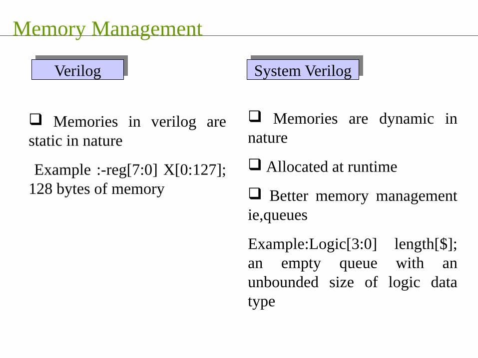
Memories in verilog are static in nature
Example :-reg[7:0] X[0:127]; 128 bytes of memory
Memories are dynamic in nature
Allocated at runtime
Better memory management ie,queues
Example:Logic[3:0] length[$]; an empty queue with an unbounded size of logic data type
VerilogVerilog System VerilogSystem Verilog
Complexity
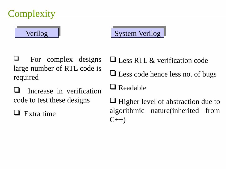
For complex designs large number of RTL code is required
Increase in verification code to test these designs
Extra time
Less RTL & verification code
Less code hence less no. of bugs
Readable
Higher level of abstraction due to algorithmic nature(inherited from C++)
VerilogVerilog System VerilogSystem Verilog

Hardware specific procedures
It uses the “always” procedure to represent
Sequential logic
Combinational logic
Latched logic
It uses three new procedures
always_ff - sequential logic
always_comb - combinational logic
always_latch - latched logic
VerilogVerilog System VerilogSystem Verilog
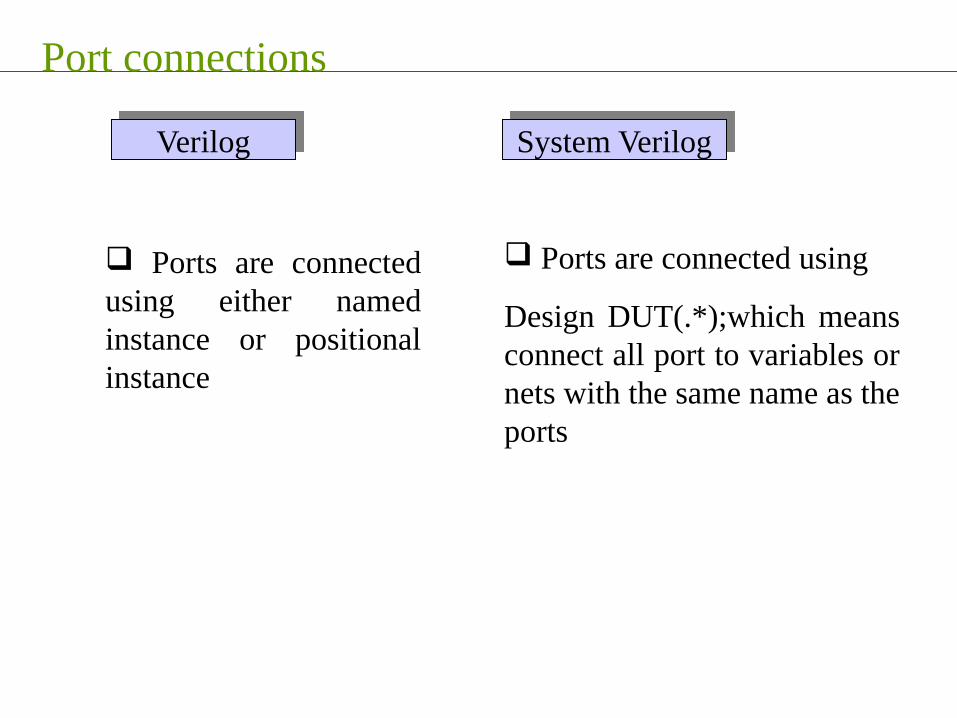
Port connections
Ports are connected using either named instance or positional instance
Ports are connected using
Design DUT(.*);which means connect all port to variables or nets with the same name as the ports
VerilogVerilog System VerilogSystem Verilog

Synthesis support
Extensive support for verilog-2001 in simulation and synthesis
Synthesis tool support for system verilog is limited
VerilogVerilog System VerilogSystem Verilog
“This is a major drawback which is restricting people to accept SystemVerilog as a Design language”
SystemVerilog Concepts

System Verilog Concepts
reg r; // 4-state Verilog-2001 logic w; // 4-valued logic, see belowbit b; // 2-state bit 0 or 1 integer i; // 4-state, 32-bits, signed Verilog-2001byte b8; // 8 bit signed integerint i; // 2-state, 32-bit signed integershortint s;// 2-state, 16-bit signed integerlongint l; // 2-state, 64-bit signed integer
Explicit 2-state variables allow compileroptimizations to improve performance
logic is has single driver (procedural assignments or a continuous assignment), can replace reg and single driver wire. (Equivalent to “std_ulogic” in VHDL)
Bit subsallowed
Data types :
System Verilog Concepts
join
fork
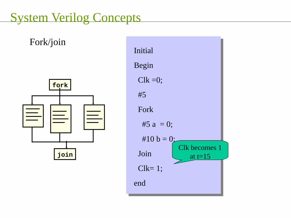
Fork/joinInitial
Begin
Clk =0;
#5
Fork
#5 a = 0;
#10 b = 0;
Join
Clk= 1;
end
Clk becomes 1 at t=15

System Verilog Concepts
Join_any
fork
Fork/join_any
Clk becomes 1 at t=10
Initial
Begin
Clk =0;
#5
Fork
#5 a = 0;
#10 b = 0;
Join_any
Clk= 1;
end
System Verilog Concepts
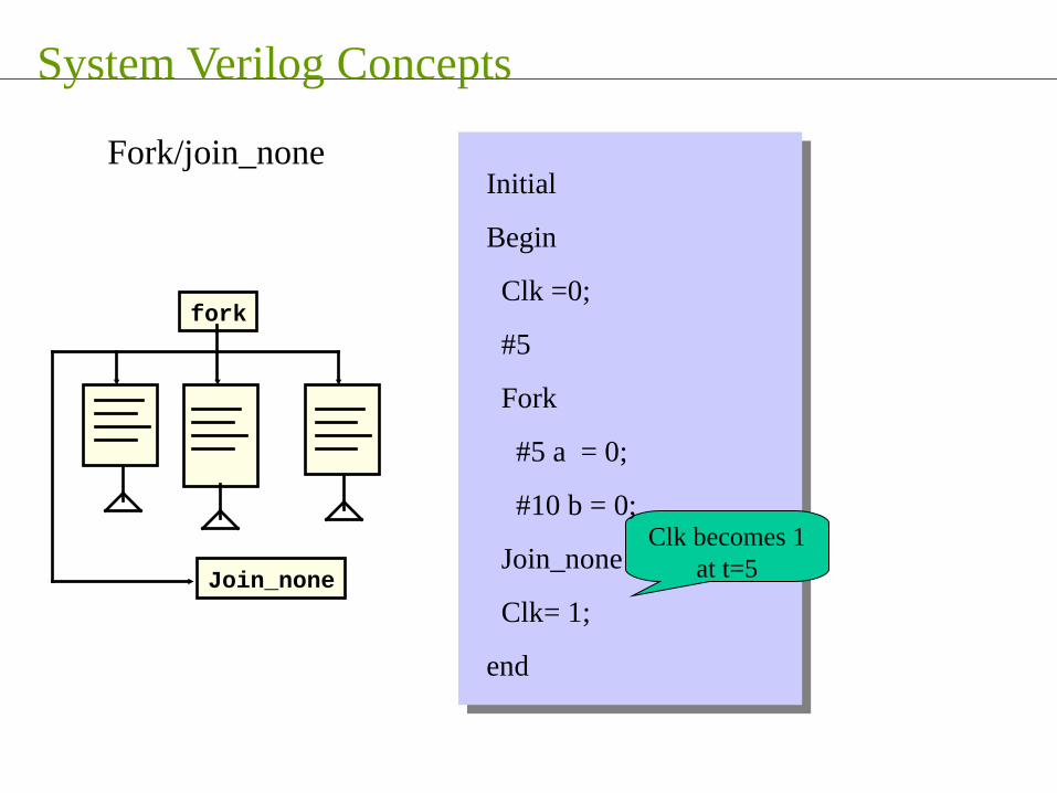
Join_none
fork
Fork/join_none
Clk becomes 1 at t=5
Initial
Begin
Clk =0;
#5
Fork
#5 a = 0;
#10 b = 0;
Join_none
Clk= 1;
end
System Verilog Concepts
Final block
Executes at the end of simulation
It can not have delays
Used in verification to print simulation results, such as error report, code coverage reports
System Verilog Concepts
Tasks & Functions
No begin end required
Return can be used in task
Function return values can have a “void return type”
Functions can have any number of inputs,outputs and inouts including none

System Verilog Concepts
DPI(Direct Programming interface )
DPI’s are used to call C, C++, System C functions
System verilog has a built in C interface
Simple to used as compared to PLI’s
Values can be passed directly

System Verilog Concepts
DPI(Direct Programming interface )
Imported functions
Exported functions
• System verilog calls the C functions
• C calls the system verilog function
Both sides of DPI are fully independent
• System verilog does not analyze the C-code
• C complier does not have to analyze the system verilog code

System Verilog Concepts
Top SystemVerilog Testbench Constructs
Queue
Mailbox
Fork/join
Class
Constraint
Covergroup
Program
Virtual interface
Clocking Block
modports

Verification Targeted Capabilities

DUT
Driver
Transactor
Monitor
Supplies datato the DUT
Supplies datato the DUT
Observesdata
from DUT
Observesdata
from DUT
Executestransactions
Executestransactions
Identifiestransactions
Identifiestransactions
Checkscorrectness
Checkscorrectness
Createsstimulus
Createsstimulus
TestbenchTestbench
Assertions
Test
Checker
Self Check
VerificationEnvironment
VerificationEnvironment
Verification environment

Verification targeted capabilities
File I/o
Random number generation
Fork/join
Initial block
Task & functions
PLI
All verilog features
Constrained random number generation
Classes
Fork/join_any,fork/join_none
Final block
Task & function enhancements
DPI
VerilogVerilog System VerilogSystem Verilog

OOP Concepts
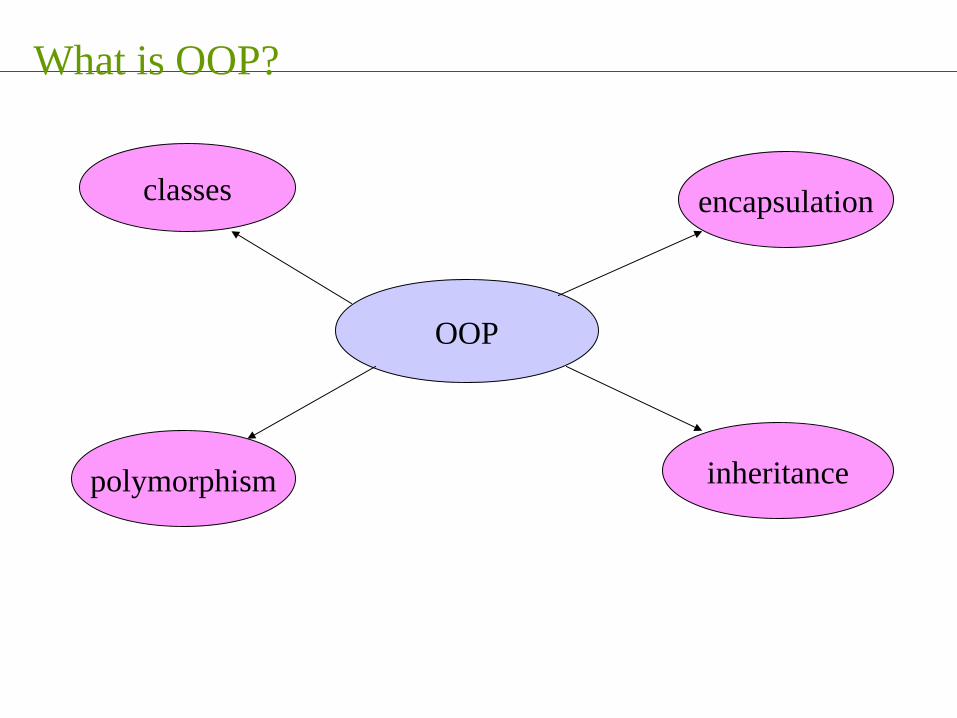
What is OOP?
OOP
encapsulationclasses
polymorphism inheritance
OOP is object oriented programming
Classes form the base of OOP programming
Encapsulation - OOP binds data & function together
Inheritance –extend the functionality of existing objects
Polymorphism – wait until runtime to bind data with functions
What is OOP?

What is OOP?
OOP breaks a testbench into blocks that work together to accomplish the verification goal
Why OOP
• Highly abstract system level modelling
• Classes are intended for verification
• Classes are easily reused and extended
• Data security
• Classes are dynamic in nature
• Easy debugging, one class at a time

Why system Verilog?
Why Not C++?
Why not C++

C++C++ System VerilogSystem Verilog
Superset of Verilog
RTL/Verification language
Assertion language
Constraint language
Code coverage language
No relation to verilog
Interface is required to interact with Verilog
Why not C++

Inheritance
Inheritance is to reuse the existing code
Inheritance allows to add new
• Data members(properties)
• New Methods
Inheritance is to share code between classes

Inheritance
Advantages
• Common code can be grouped into one class
• No need to modify the existing classes
• Add new features to existing class by means of new derived classes
• Easy debug & easy to maintain the code base

Randomization
Randomization
Why Randomization ?
• Random generation of stimulus
• Random setting of parameters
• Hard-to-reach corner cases can be reached

Shift from directed to random
Randomization
DirectedDirected RandomRandom
Detect the expected bugs
Time consuming
Detects unexpected bugs (corner cases)
Tremendously reduce the efforts

Randomization
Constrained Randomization
Improves the result
Speed-up the bug finding process
More interesting cases can be achieved within the constrained boundary

Assertions

Assertion
Used primarily to validate the behaviour of a design
An assertion is a statement about a designs intended behaviour
In-line assertions are best added by design engineers
Interface assertions are best added by verification engineers
An assertion’s sole purpose is to ensure consistency between the designer’s intention and design implementation
It increases the bug detection possibility during RTL design phase
Crux
Crux
SystemVerilog
Is a unified language (HDVL)
Reduce the design cycle
Verify that designs are functionally correct
Greatly increase the ability to model huge designs
Incorporates the capability of Vera & powerful assertion constructs
Bridges the gap between Hardware design engineer and verification engineer


Verification withSystemVerilog

This Presentation is…
Focused on “SystemVerilog” Testbench constructs
It’s a platform for open discussion on “SystemVerilog”
References
Websources:
1. www.systemverilog.org
3. http://svug.org/
Books :
1. Writing Testbenches using SystemVerilog - Janick Bergeron 2. Verification Methodology Manual - Janick Bergeron 3. SystemVerilog For Verification - Chris Spear

Top SystemVerilog Testbench Constructs
Queue
Mailbox
Fork/join
Semaphore
Constraint
Covergroup
Program
Interface
Clocking Block
modports
We will discuss…

Queue…
Data storage array [$]• Variable size array with automatic sizing
• Searching, sorting and insertion methods

Mailbox
Fifo with flow control• passes data between two processes
• put() – stimgen calls put() to pass data to bfm
• get() – bfm calls get() to retrieve data from stimgen
mailbox
stimgen bfm
put() get()

Mailbox
mailbox mbx;
mbx = new(); // allocate mailbox
mbx.put(data); // Put data object into mailbox
mbx.get(data); // data will be updated with data from FIFO
success = mbx.try_get(ref data); // Non-blocking version
mbx.peek(data); // Look but don’t remove
count = mbx.num(); // Number of elements in mailbox

Fork/join
join
fork
Fork/joinInitial
Begin
Clk =0;
#5
Fork
#5 a = 0;
#10 b = 0;
Join
Clk= 1;
end
Clk becomes 1 at t=15

Fork/join
Join_any
fork
Fork/join_any
Clk becomes 1 at t=10
Initial
Begin
Clk =0;
#5
Fork
#5 a = 0;
#10 b = 0;
Join_any
Clk= 1;
end

Fork/join
Join_none
fork
Fork/join_none
Clk becomes 1 at t=5
Initial
Begin
Clk =0;
#5
Fork
#5 a = 0;
#10 b = 0;
Join_none
Clk= 1;
end
Semaphore
Used for Synchronization• Variable number of keys can be put and removed
• controlled access to a shared object
• think of two people wanting to drive the same car – the key is a semaphore

Constraint
Control randomization• Values for random variable can be controlled through constraint expressions
• These are declared within constraint block
Class packet ;
rand logic [7:0] src;
rand logic [7:0] dest;
Constraint my_constraints {
src[1:0] == 2’b00; // constraint expression
…………… // always set src[1:0] to 0
}
endclass:packet
Class packet ;
rand logic [7:0] src;
rand logic [7:0] dest;
Constraint my_constraints {
src[1:0] == 2’b00; // constraint expression
…………… // always set src[1:0] to 0
}
endclass:packet

Covergroup
Captures results from a random simulation
Encapsulates the coverage specification• bins
• transitions
Covergroup check @(posedge top.valid );
coverpoint global;
coverpoint top.test;
endgroup:check
………………
check chk = new();
Covergroup check @(posedge top.valid );
coverpoint global;
coverpoint top.test;
endgroup:check
………………
check chk = new();

Program Block
Benefits:• Encapsulates the testbench
• Separates the testbench from the DUT
• Provides an entry point for execution
• Creates a scope to encapsulate program-wide data
Functionality:• Can be instantiated in any hierarchical location
Typically at the top level
• Ports can be connected in the same manner as any other module
• Executes in the SV reactive region

Program Block
The testbench (program) runs separately from design (module)
• Triggered by clock
• Samples just before clock edge, drives just after clock
clock
Sampleinputs
Driveoutputs
Design
Testbench
Interface
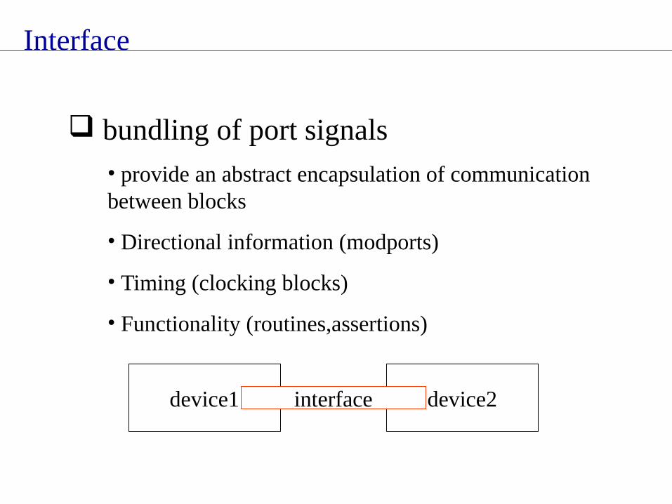
bundling of port signals• provide an abstract encapsulation of communication between blocks
• Directional information (modports)
• Timing (clocking blocks)
• Functionality (routines,assertions)
device1 device2interface
Interface
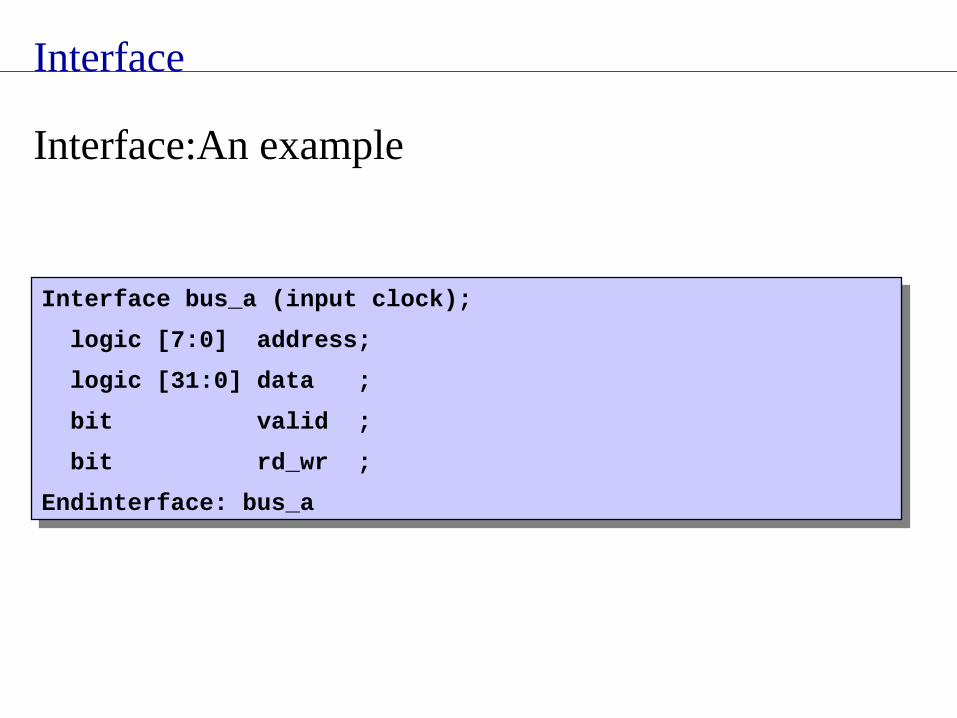
Interface bus_a (input clock);
logic [7:0] address;
logic [31:0] data ;
bit valid ;
bit rd_wr ;
Endinterface: bus_a
Interface bus_a (input clock);
logic [7:0] address;
logic [31:0] data ;
bit valid ;
bit rd_wr ;
Endinterface: bus_a
Interface:An example

Clocking Block
Specify synchronization characteristics of the design
Offer a clean way to drive and sample signals
Features• Clock specification
• Input skew,output skew
• Cycle delay (##)
Clocking Block
Can be declared inside interface,module or program
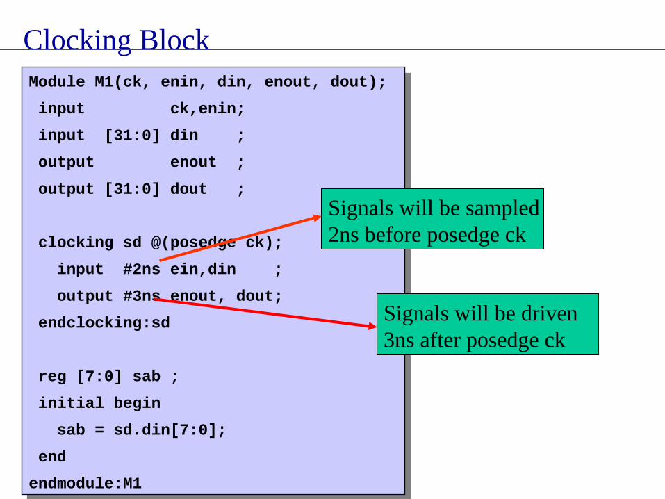
Clocking Block
Module M1(ck, enin, din, enout, dout);
input ck,enin;
input [31:0] din ;
output enout ;
output [31:0] dout ;
clocking sd @(posedge ck);
input #2ns ein,din ;
output #3ns enout, dout;
endclocking:sd
reg [7:0] sab ;
initial begin
sab = sd.din[7:0];
end
endmodule:M1
Module M1(ck, enin, din, enout, dout);
input ck,enin;
input [31:0] din ;
output enout ;
output [31:0] dout ;
clocking sd @(posedge ck);
input #2ns ein,din ;
output #3ns enout, dout;
endclocking:sd
reg [7:0] sab ;
initial begin
sab = sd.din[7:0];
end
endmodule:M1
Signals will be sampled 2ns before posedge ck
Signals will be driven 3ns after posedge ck
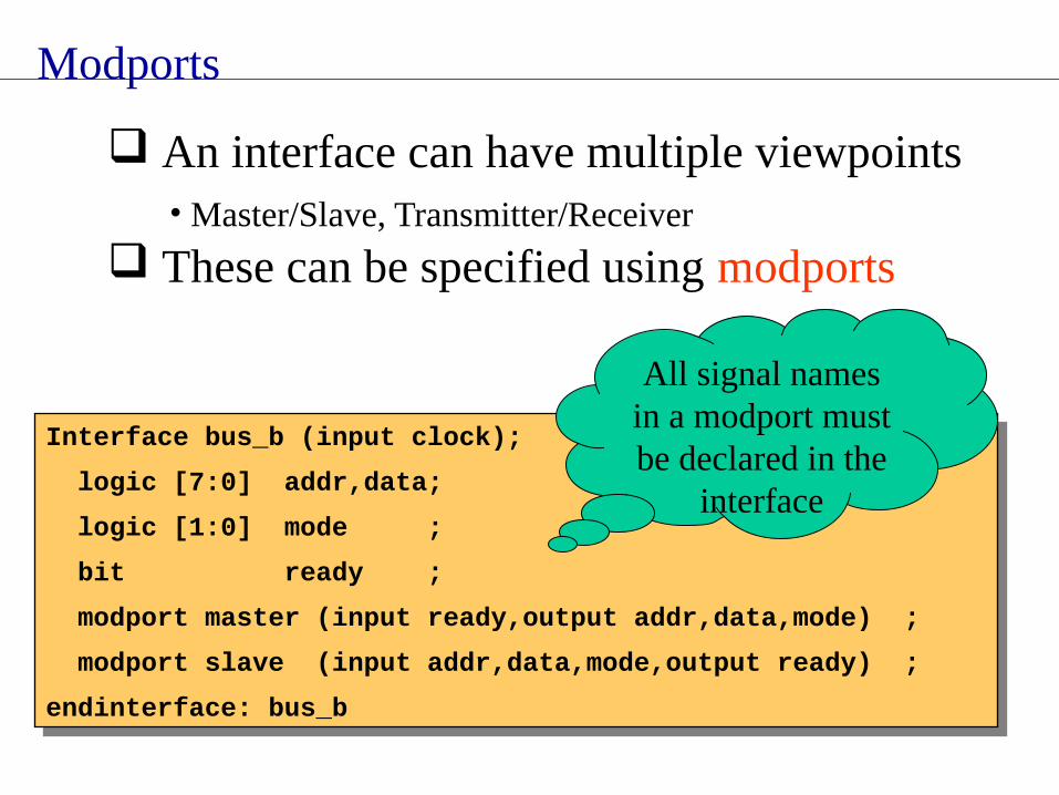
Modports
An interface can have multiple viewpoints• Master/Slave, Transmitter/Receiver
These can be specified using modports
Interface bus_b (input clock);
logic [7:0] addr,data;
logic [1:0] mode ;
bit ready ;
modport master (input ready,output addr,data,mode) ;
modport slave (input addr,data,mode,output ready) ;
endinterface: bus_b
Interface bus_b (input clock);
logic [7:0] addr,data;
logic [1:0] mode ;
bit ready ;
modport master (input ready,output addr,data,mode) ;
modport slave (input addr,data,mode,output ready) ;
endinterface: bus_b
All signal names in a modport must be declared in the
interface

Conclusion
Some of SystemVerilog Testbench constructs were discussed
But still a long way to go……..

Thank you


