Page 1
An Approved Continuing Education Provider
PDHonline Course M506 (4 PDH)
An Introduction to Steam Boilers and
Turbines for Power Plants
J. Paul Guyer, P.E., R.A.
2013
PDH Online | PDH Center
5272 Meadow Estates Drive
Fairfax, VA 22030-6658
Phone & Fax: 703-988-0088
www.PDHonline.org
www.PDHcenter.com
Page 2
www.PDHcenter.com PDHonline Course M506 www.PDHonline.org
©2013 J. Paul Guyer Page 2 of 61
An Introduction to Steam Boilers and
Turbines for Power Plants
J. Paul Guyer, P.E., R.A.
CONTENTS
1. POWER PLANT STEAM GENERATION
2. STEAM TURBINE DESIGN
(This publication is adapted from the Unified Facilities Criteria of the United States government which are in the public domain, have been authorized for unlimited distribution, and are not copyrighted.) (Figures, tables and formulas in this publication may at times be a little difficult to read, but they are the best available. DO NOT PURCHASE THIS PUBLICATION IF THIS LIMITATION IS UNACCEPTABLE TO YOU.)
Page 3
www.PDHcenter.com PDHonline Course M506 www.PDHonline.org
©2013 J. Paul Guyer Page 3 of 61
1. POWER PLANT STEAM GENERATION
1.1 STEAM GENERATORS (BOILERS). For collateral reading and further detailed
information, see (1) Steam Generation and Use, by Babcock & Wilcox, 1978 and (2)
Combustion/Fossil Power Systems, by Combustion Engineering, Inc, 1981.
1.2 STEAM PRESSURES AND TEMPERATURES
1.2.1 RATED PRESSURE AND TEMPERATURE. The boiler shall be specified for the
maximum operating steam pressure required at the superheater outlet for operation of
the turbine generator. The specified operating pressure is the maximum operating
pressure at the turbine throttle valve inlet plus the main steam line pressure drop
(between the superheater outlet and turbine throttle valve inlet at the maximum
continuous rating of the boiler) rounded to the next higher unit of 5 psi (34 kPa gage).
Based on the specified operating pressure, the boiler manufacturers will design the
boiler parts and safety valve pressure settings in accordance with the ASME Boiler
and Pressure Vessel Code, Section 1, Power Boilers. The boiler shall be specified for
the maximum steam temperature required at the superheater outlet for operation of
the turbine generator. The specified temperature is equal to the sum of the operating
temperature at the turbine throttle valve inlet plus the main steam temperature drop
(between the superheater outlet and turbine throttle valve inlet) with the sum rounded
out to the next higher unit of 5 degrees F.
1.2.2 MAXIMUM ALLOWABLE WORKING PRESSURE. The maximum allowable
working pressure (MAWP) of a boiler is an absolute limit of pressure in psig at which a
boiler is permitted to operate. The ASME Boiler and Pressure Vessel Code states that
no boiler shall be operated at a pressure higher than the MAWP except when the
safety valve or valves are discharging (blowing).
Page 4
www.PDHcenter.com PDHonline Course M506 www.PDHonline.org
©2013 J. Paul Guyer Page 4 of 61
1.2.2.1 SAFETY VALVES AND SAFETY RELIEF VALVES. In accordance with the
rules of the ASME Boiler and Pressure Vessel Code, one or more safety valves on the
boiler shall be set at or below the MAWP. If additional safety valves are used, the
highest pressure setting shall not exceed the MAWP by more than 3 percent. The
capacity of all safety valves or safety relief valves for each boiler shall be such that the
valves will discharge all the steam that can be generated without allowing the pressure
to rise more than 6 percent above the highest pressure at which any valve is set and in
no case higher than 6 percent above the MAWP.
1.2.2.2 NORMAL OPERATING PRESSURE. In order to avoid excessive use and
wear of safety or safety relief valves, the maximum boiler operating pressure in the
boiler steam drum or at the superheater outlet is usually not greater than 95 percent of
the lowest set pressure of the relief valves at these points. This allows operation of the
boiler below the blowdown range of the safety valves, which is usually 3 to 4 percent
of the set pressure.
1.3 NATURAL GAS FIRING. For natural gas characteristics and application, see the
technical literature.
1.4 FUEL OIL FIRING. For fuel oil characteristics, application, handling, storage, and
burning, see the technical literature.
1.5 COAL FIRING. For characteristics, application, handling, and storage of
coal, see the technical literature.
1.5.1 DEFINITIONS OF BOILER AND STOKER CRITERIA.
1.5.1.1 STOKER GRATE BURNING RATE. Burning rate is the higher heating value
(in Btu) of the type of coal used multiplied by the number of pounds of coal burned per
hour to obtain the rated boiler capacity; divided by the total active burning area, in
square feet, of the stoker grate. The maximum values shown are based on the
Page 5
www.PDHcenter.com PDHonline Course M506 www.PDHonline.org
©2013 J. Paul Guyer Page 5 of 61
assumption that furnace walls are water cooled, that there is adequate furnace
volume, and that the most desirable type of coal for the unit is used; in the absence of
these conditions, values should be reduced to ensure satisfactory combustion.
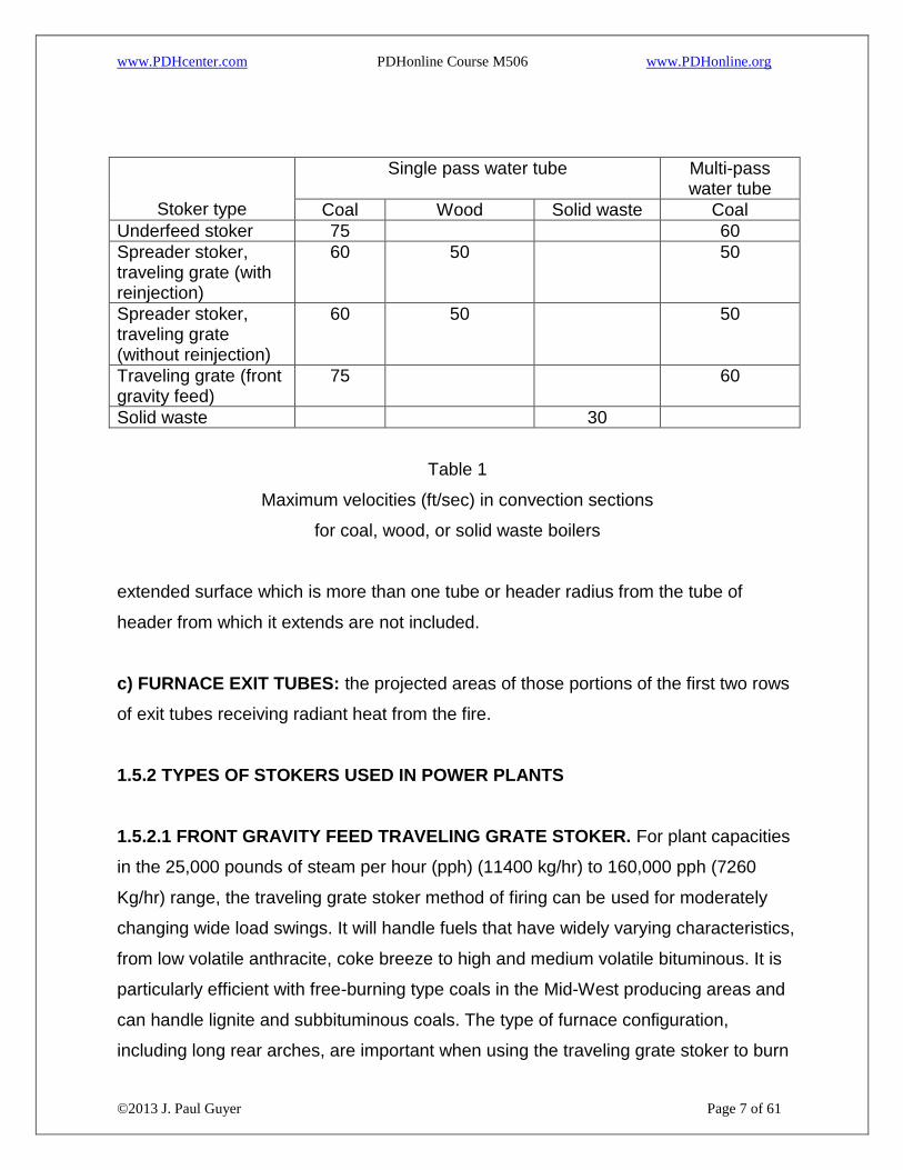
1.5.1.2 VELOCITIES IN CONVECTION SECTIONS OF BOILERS. To prevent undue
erosion of boiler convection tubes, the gas velocities through the convection section
shall not exceed velocities shown in Table 1 for the specific boiler, stoker, and fuel
combination.
1.5.1.3 FURNACE VOLUME. For water-tube boilers, furnace volume is defined as the
cubical volume between the top grate surface (coal) or the floor (gas, oil) and the first
plane of entry into or between the tubes. If screen tubes are utilized, they constitute
the plane of entry.
1.5.1.4 EFFECTIVE RADIANT HEATING SURFACE. Effective radiant heating surface
is defined as the heat-exchange surface within the furnace boundaries and, in solid-
fuel furnaces, above the grate surface that is directly exposed to radiant heat of the
flame on one side and to the medium being heated on the other. This surface consists
of plain or finned tubes and headers and plain surfaces, which may be bare, metal-
covered, or metallic-ore-covered. Refractory-covered surfaces should not be counted.
The surface shall be measured on the side receiving heat. Computations of effective
radiant heating surface for water tube boilers shall be based on the following:
a) BARE, METAL-COVERED, OR METALLIC-ORE-COVERED TUBES AND
HEADERS: projected area (external diameter times length of tube) of the tubes or
header.
b) EXTENDED SURFACE (METAL AND METALLIC SURFACES EXTENDING
FROM THE TUBES OR HEADERS): Sixty percent of the flat projected area, except
that metal blocks not integral with tubes or headers, extended surfaces less than 1/4
Page 6
www.PDHcenter.com PDHonline Course M506 www.PDHonline.org
©2013 J. Paul Guyer Page 6 of 61
inch (6.35 mm) thick or more than 1-1/4 inches (31.75 mm) in length, and the part of
the
Page 7
www.PDHcenter.com PDHonline Course M506 www.PDHonline.org
©2013 J. Paul Guyer Page 7 of 61
Stoker type
Single pass water tube Multi-pass water tube
Coal Wood Solid waste Coal
Underfeed stoker 75 60
Spreader stoker, traveling grate (with reinjection)
60 50 50
Spreader stoker, traveling grate (without reinjection)
60 50 50
Traveling grate (front gravity feed)
75 60
Solid waste 30
Table 1
Maximum velocities (ft/sec) in convection sections
for coal, wood, or solid waste boilers
extended surface which is more than one tube or header radius from the tube of
header from which it extends are not included.
c) FURNACE EXIT TUBES: the projected areas of those portions of the first two rows
of exit tubes receiving radiant heat from the fire.
1.5.2 TYPES OF STOKERS USED IN POWER PLANTS
1.5.2.1 FRONT GRAVITY FEED TRAVELING GRATE STOKER. For plant capacities
in the 25,000 pounds of steam per hour (pph) (11400 kg/hr) to 160,000 pph (7260
Kg/hr) range, the traveling grate stoker method of firing can be used for moderately
changing wide load swings. It will handle fuels that have widely varying characteristics,
from low volatile anthracite, coke breeze to high and medium volatile bituminous. It is
particularly efficient with free-burning type coals in the Mid-West producing areas and
can handle lignite and subbituminous coals. The type of furnace configuration,
including long rear arches, are important when using the traveling grate stoker to burn
Page 8
www.PDHcenter.com PDHonline Course M506 www.PDHonline.org
©2013 J. Paul Guyer Page 8 of 61
very low volatile fuels, such as anthracite or coke breeze. Front arches are used with
the high volatile and free-burning Mid-Western type coals. The feature of the traveling
grate stoker that provides for the utilization of such a wide variety of fuel types is the
undergrate air zoning. These units normally have from five to nine individual air zones
which can control the amount of air admitted to the fuel bed as it travels from the free
end of the stoker to the discharge. This provides the stoker operation with tremendous
flexibility to obtain complete combustion with the various sizes and types of fuel. Since
the fuel bed on the traveling grate stoker is not agitated by vibration as the bed usually
4 inches (101.6 mm) to 6 inches (152.4 mm) depth is moving from the feed end toward
the discharge end, the amount of particulate fluidization is very low. This means that
the traveling grate stoker has a low particulate pollution characteristic as compared to
other fuel burning stokers. Chain grate stokers are not recommended except to burn
low fusion coals with high clinkering tendencies.
1.5.2.2 OVERFEED SPREADER STOKER WITH TRAVELING GRATE. The spreader
stoker is characterized by a thin bed and partial burning of coal particles in
suspension. Suspension burning gives rapid response to load changes which is an
important characteristic for many industrial process steam plants that need rapid
changes in steam production. This characteristic, together with a nonclinkering thin
bed on the grate, provides a unit capable of firing a wide range of coal grades and
types. The spreader stoker has high availability, ease of operation, and good
efficiency. The suspension burning causes a high particulate loading of the burning
gases within the furnace which, without fly ash reinjection, would result in a high
carbon loss in the fly ash. Front discharge traveling grates are commonly used with
spreader stokers. (Dump, vibrating, reciprocating, and oscillating grates are also
available). With a high particulate loading, the spreader stoker requires the use of
electrostatic precipitator or baghouse
collectors to prevent particulate pollution.
Page 9
www.PDHcenter.com PDHonline Course M506 www.PDHonline.org
©2013 J. Paul Guyer Page 9 of 61
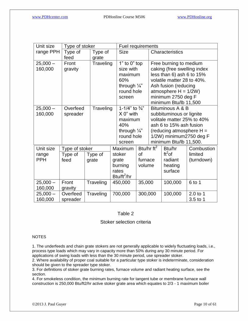
1.5.3 STOKER CRITERIA. See Table 2, Stoker Selection Criteria, for information
necessary for proper selection of a stoker type. Information included in the table are
average criteria gathered from several boiler-stoker manufacturers' recommendations.
1.5.4 PULVERIZED COAL
1.5.4.1 COAL FEEDERS. For use with each pulverizer, the coal feeding function can
be accomplished by the use of a separate rotary feeder or combined with the weighing
Function using a volumetric or gravimetric feeder. Pulverizers, depending on type, may
operate with either a negative or positive internal pressure and will also contain hot
circulating air. Coal feeders cannot act as a seal for the pulverizer air, therefore, a
height (head) of coal must be provided and maintained above the feeder inlet to
prevent pulverizer air backflow.
Page 10
www.PDHcenter.com PDHonline Course M506 www.PDHonline.org
©2013 J. Paul Guyer Page 10 of 61
Unit size range PPH
Type of stoker Fuel requirements
Type of feed
Type of grate
Size Characteristics
25,000 – 160,000
Front gravity
Traveling 1” to 0” top size with maximum 60% through ¼” round hole screen
Free burning to medium caking (free swelling index less than 6) ash 6 to 15% volatile matter 28 to 40%. Ash fusion (reducing atmosphere H = 1/2W) minimum 2750 deg F minimum Btu/lb 11,500
25,000 – 160,000
Overfeed spreader
Traveling 1-1/4” to ¾” X 0” with maximum 40% through ¼” round hole screen
Bituminous A & B subbituminous or lignite volitale matter 25% to 40% ash 6 to 15% ash fusion (reducing atmosphere H = 1/2W) minimum2750 deg F minimum Btu/lb 11,500.
Unit size range PPH
Type of stoker Maximum stoker grate burning rates Btu/ft2/hr
Btu/hr ft2 of furnace volume
Btu/hr ft2of radiant heating surface
Combustion limited (turndown)
Type of feed
Type of grate
25,000 – 160,000
Front gravity
Traveling 450,000 35,000 100,000 6 to 1
25,000 – 160,000
Overfeed spreader
Traveling 700,000 300,000 100,000 2.0 to 1 3.5 to 1
Table 2
Stoker selection criteria
NOTES 1. The underfeeds and chain grate stokers are not generally applicable to widely fluctuating loads, i.e., process type loads which may vary in capacity more than 50% during any 30 minute period. For applications of swing loads with less than the 30 minute period, use spreader stoker. 2. Where availability of proper coal suitable for a particular type stoker is indeterminate, consideration should be given to the spreader type stoker. 3. For definitions of stoker grate burning rates, furnace volume and radiant heating surface, see the section. 4. For smokeless condition, the minimum burning rate for tangent tube or membrane furnace wall construction is 250,000 Btu/ft2/hr active stoker grate area which equates to 2/3 - 1 maximum boiler
Page 11
www.PDHcenter.com PDHonline Course M506 www.PDHonline.org
©2013 J. Paul Guyer Page 11 of 61
turndown, with a tube and tile (spaced tubes backed by refractory) or refractory furnace. This release rate can be reduced to 200,000 Btu/ft2/hr which equates to 3.5 - 1 maximum boiler turndown 5. All grate heat release rates are based on maximum continuous rating (MCR) with allowance for 110% rating for 2 hour emergency peak per 24 hours. 6. Coal with volatile content less than indicated should not be applied, as loss of ignition could result. 7. Some chain grate designs are applicable for anthracite coal firing. 8. Further turndown beyond that indicated under Note 4 may be obtainable dependent upon allowable emission requirements and/or pollution abatement equipment applied. 9.. Consult boiler and stoker manufacturers for predicted excess air requirements at various loads. 10. In cases where coal quality is less than in above tables, consult NAVFAC headquarters Code 04 for direction.
1.5.4.2 PULVERIZERS. Pulverizers are used to reduce crushed coal to a powder-like
fineness usually in the order of 70 percent passing through a 200 mesh screen. To
facilitate the pulverizing and pneumatic circulation of the coal fuel within the pulverizer,
hot air (up to 650 degrees F (343 degrees C)) is introduced into the pulverizer for the
purpose of drying the coal. A pulverizer fan is used either as a blower or exhauster
which either forces or draws hot primary air through the pulverizer and through the
discharge coal-air piping to the burners. If a blower is used, one pulverizer will usually
furnish coal directly to several burners. If an exhauster is used, a distributor located
beyond the fan discharge is used to distribute the coal-air mixture to several burners.
1.5.4.2.1 TYPES OF PULVERIZERS. The principal types of pulverizers are as
follows:
(1) Ball and race
(2) Roll and race
(3) Ball tube
(4) Attrition
The various types are described in detail in the following boiler manufacturers'
literature: (1) Babcock & Wilcox, 1978, (2) Combustion Engineering, Inc, 1981.
1.5.4.2.2 TURNDOWN RATIO. The operating range of all types of pulverizers, without
reducing the number of burners fed from the pulverizer(s) is approximately 35 percent
Page 12
www.PDHcenter.com PDHonline Course M506 www.PDHonline.org
©2013 J. Paul Guyer Page 12 of 61
to 100 percent of the maximum pulverizer coal capacity. This is usually stated as not
more than 3 to 1 turndown range or ratio.
1.5.4.2.3 PULVERIZER SIZING. Base pulverizer selection on coal feed is required at
maximum boiler load plus 10 percent for load pickup and continuous boiler output at
maximum steam load. Pulverizer output varies with coal grindability index and fineness
(percent through 200 mesh) of grind. These factors must also be taken into account in
selecting number and size of pulverizers. Emergency loss of one pulverizer must be
considered and the remaining pulverizer capacity must be sufficient to carry maximum
boiler steam load. The minimum boiler load will depend on the number of pulverizers
and burners installed and primary air velocities in the coal-air piping and coal burners.
It is desirable to have at least a 3 to 1 turndown on automatic control with all burners
and pulverizers in service. During boiler startup, the firing rate may be further reduced
by reducing the number of pulverizers and number of burners per pulverizer in service.
Sizing of pulverizers must be coordinated with the boiler manufacturer and usually
requires the development of a set of coordination curves of the various factors
involved.
1.5.4.2.4 COAL FEED SIZE. Crushed coal is used as the feed stock for pulverizers.
The maximum coal feed size is dependent upon pulverizer size. The larger the
pulverizer size, the larger is the coal size which can be accommodated. Coal feed size
ranges from 3/4" (19.05 mm) x 0" to 1-1/2" (38.1 mm) x 0" with 3/4" x 0" being a size
which is commonly used.
1.5.5 PULVERIZED COAL FIRING VS. STOKER COAL FIRING. The choice between
the use of pulverizers or stokers can only be determined by making an economical
evaluation of life cycle costs which include cost of equipment and installation, fuel,
maintenance labor and parts, operating labor, electrical energy, electrical demand, and
supplies. For many years, for industrial power applications, the boiler size breakpoint
was approximately 300,000 pph (136 000 kg/hr) with pulverizers predominantly used
at this boiler load and above. Presently there is a downward trend and the breakpoint
Page 13
www.PDHcenter.com PDHonline Course M506 www.PDHonline.org
©2013 J. Paul Guyer Page 13 of 61
for boiler size is approximately 250,000 pph (113 000 kg/hr). Pulverized coal systems
are of high installation costs, high power costs to drive mills, more rigid coal
specifications, and need highly trained personnel.
1.5.6 COAL SCALES. Coal scales are also used to measure coal feed to stokers or
pulverizers. These are located at the in-plant bunker outlet and may be of the batch
weigh bucket, volumetric (volume rate of flow measurement) belt, or gravimetric
(weight rate of flow measurement) belt type.
1.6 WOOD FIRING. The usual practice when burning wood is to propel the wood
particles into the furnace through injectors, along with preheated air, with the purpose
of inducing high turbulence in the boiler. The wood is injected high enough in the
combustion chamber so that it is dried, and all but the largest particles are burned
before they reach the grate at the bottom of the furnace. Spreader stokers and cyclone
burners work well for this application. For burning wood as a fuel to produce steam or
high temperature water (HTW), methods should be researched thoroughly and their
successful operation, adequate source of fuel, and economics evaluated.
1.6.1 SUSPENSION BURNING. Small wood chips or saw dust are blown into the
furnace chamber and burned in suspension. The ash or unburned particles are
collected on traveling grate and transported to ash pit. In wood burning applications,
heat releases have been as high as 1,000,000 Btu/ft2/hr. (11 357 373 kJ/m2/hr) of
active grate area.
1.7 SOOT BLOWERS. Soot blowers are required for No. 6 fuel oil, coal, and wood
and may or may not be required for No. 2 fuel oil.
1.8 ECONOMIZERS. Economizers are located in the boiler flue gas outlet duct and
are used to heat the incoming feedwater by reducing the flue gas temperature. The
result is an increase in boiler efficiency.
Page 14
www.PDHcenter.com PDHonline Course M506 www.PDHonline.org
©2013 J. Paul Guyer Page 14 of 61
1.9 AIR HEATERS. Air heaters should be used to burn bark and wood chips and may
be used for other fuels if economically justified or required for combustion.
1.10 FORCED DRAFT FANS. For forced draft fan size, types, drives, and general
requirements, refer to the technical literature.
1.11 INDUCED DRAFT FANS. When flue gas scrubbers are used, the induced draft
fans must be able to accommodate the boiler full test steam load when the scrubbers
are not in operation. In addition, allowances must be made for leakage and pressure
requirements for air pollution control equipment.
1.12 PRIMARY AIR FANS. Primary air fans may be used on large pulverized coal
fired boilers in lieu of pulverizer blowers or exhausters. Primary air fans usually provide
both hot and cold air which can be tempered before being introduced into the
pulverizers. The cold air is atmospheric air supplied from the fan discharge. Part of the
fan discharge goes through a section of the air heater or separate air heater which in
turn raises the temperature to 500 degrees F (260 degrees C) or 600 degrees F (315
degrees C). The hot air is then ducted and tempered with the cold air to provide the
motive and drying air to the pulverizers at the proper temperature.
1.13 OVERFIRE AIR FANS. Overfire air fans are used on stoker fed coal fired boilers
to reduce smoke and to improve combustion efficiency by mixing with unburned gases
and smoke. The quantity of overfire air is usually between 5 and 15 percent of the total
air needed for combustion of the coal fuel. The pressure and volume of overfire air
must be sufficient to produce the proper turbulence for efficient burnup of the
unburned gases and suspended fuel particles. Fan size is determined by the boiler
manufacturer and furnished with the boiler.
1.14 CINDER RETURN FANS. Cinder return fans are used on some stoker fed coal
fired boilers for reinjection of fly ash from last pass hoppers and mechanical dust
Page 15
www.PDHcenter.com PDHonline Course M506 www.PDHonline.org
©2013 J. Paul Guyer Page 15 of 61
collectors. Fan size is determined by the boiler manufacturer and furnished with the
boiler.
1.15 STACKS. For description and sizing of stacks, see the technical literature.
1.16 BLOWDOWN EQUIPMENT. For information relative to boiler blowdown and
blowdown equipment, refer to the technical literature.
1.17 ESSENTIAL PLANT EQUIPMENT
1.17.1 STEAM DRIVE AUXILIARIES. On coal stoker-fired installations, steam driven
boiler feed pumps, with total pumping capacity to suit the ultimate plant capacity, are
required to satisfy the ASME Boiler and Pressure Vessel Code (Section 1, Paragraph
PG-61) requirement of two means of feeding water. These pumps shall be primarily
connected to the boiler feed header from the deaerator and also to the treated water
line for an emergency water source for the boilers.
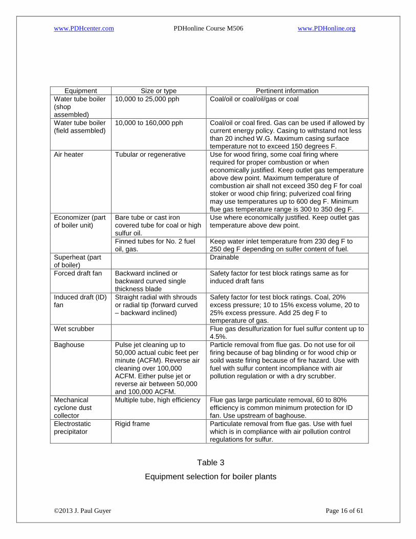
1.18 EQUIPMENT SELECTION. For design information and requirements needed to
design boiler plants, see Table 3.
Page 16
www.PDHcenter.com PDHonline Course M506 www.PDHonline.org
©2013 J. Paul Guyer Page 16 of 61
Equipment Size or type Pertinent information
Water tube boiler (shop assembled)
10,000 to 25,000 pph Coal/oil or coal/oil/gas or coal
Water tube boiler (field assembled)
10,000 to 160,000 pph Coal/oil or coal fired. Gas can be used if allowed by current energy policy. Casing to withstand not less than 20 inched W.G. Maximum casing surface temperature not to exceed 150 degrees F.
Air heater Tubular or regenerative Use for wood firing, some coal firing where required for proper combustion or when economically justified. Keep outlet gas temperature above dew point. Maximum temperature of combustion air shall not exceed 350 deg F for coal stoker or wood chip firing; pulverized coal firing may use temperatures up to 600 deg F. Minimum flue gas temperature range is 300 to 350 deg F.
Economizer (part of boiler unit)
Bare tube or cast iron covered tube for coal or high sulfur oil.
Use where economically justified. Keep outlet gas temperature above dew point.
Finned tubes for No. 2 fuel oil, gas.
Keep water inlet temperature from 230 deg F to 250 deg F depending on sulfer content of fuel.
Superheat (part of boiler)
Drainable
Forced draft fan Backward inclined or backward curved single thickness blade
Safety factor for test block ratings same as for induced draft fans
Induced draft (ID) fan
Straight radial with shrouds or radial tip (forward curved – backward inclined)
Safety factor for test block ratings. Coal, 20% excess pressure; 10 to 15% excess volume, 20 to 25% excess pressure. Add 25 deg F to temperature of gas.
Wet scrubber Flue gas desulfurization for fuel sulfur content up to 4.5%.
Baghouse Pulse jet cleaning up to 50,000 actual cubic feet per minute (ACFM). Reverse air cleaning over 100,000 ACFM. Either pulse jet or reverse air between 50,000 and 100,000 ACFM.
Particle removal from flue gas. Do not use for oil firing because of bag blinding or for wood chip or soild waste firing because of fire hazard. Use with fuel with sulfur content incompliance with air pollution regulation or with a dry scrubber.
Mechanical cyclone dust collector
Multiple tube, high efficiency Flue gas large particulate removal, 60 to 80% efficiency is common minimum protection for ID fan. Use upstream of baghouse.
Electrostatic precipitator
Rigid frame Particulate removal from flue gas. Use with fuel which is in compliance with air pollution control regulations for sulfur.
Table 3
Equipment selection for boiler plants
Page 17
www.PDHcenter.com PDHonline Course M506 www.PDHonline.org
©2013 J. Paul Guyer Page 17 of 61
Equipment Size or type Pertinent information
Soot blowers Compressed air or steam operated
Required for burning No. 6 fuel oil and coal and possibly for No. 2 fuel oil. Not required for gas firing.
Condensate receiver
60 to 180 minute storage capacity at ultimate plant capacity.
Steel plate tank with corrosion resistant liner suitable for 250 deg F.
For automatic extraction plant use 180 minutes. For straight condensing plant use 60 to 90 minutes.
Deaerating heater and tank
15 to 20 minutes storage capacity at ultimate plant capacity
Tray type to be used. Use with multiport back pressure relief valve.
Boiler feed pumps (centrifugal)
Coal fired plants and oil or gas fired boilers: one motor driven pump per boiler. Pump to be 1.25 x boiler steaming capacity; plus two steam driven pumps 1.25 x half of ultimate plant capacity.
For adequate minimum pump flow, use automatic flow control valve or automatically controlled discharge system for each pump. Discharge water to deaerator storage tank. Consider variable speed drive and steam turbine drive with clutch to permit instantaneous changeover from one drive to the other.
Condenser condensate pumps
Two per condenser. Size each for 1.25 x condenser maximum flow rate.
Horizontal split case or vertical can type pumps.
Condensate transfer pumps
Two motor driven pumps per boiler. Each pump to be 1.25 x boiler steaming capacity. Consider one steam driven pump on lieu of one of the motor driven pumps.
Provide bypass orifice at each pump. Discharge of bypass to go to condensate tank. Consider variable speed drive if over 10 hp. Horizontal split case or vertical can type pumps.
Feedwater regulators
Two element (steam flow/drum level) pump control or three element (drum level, steam flow, water flow) pump control.
Use three element pump control where boilers are operated simultaneously or have severely fluctuating loads.
Steam turbines for mechanical drive
Size for maximum horsepower required under all possible operating conditions
Can be used for condensate transfer pump, boiler feed pump, forced draft fan, induced draft fan, over fire fan. Use to reduce electric consumption of heating plant. Assure sufficient electric auxiliaries to preclude atmospheric exhaust during low-load periods. Consider both motor drive and steam turbine drive with overrunning clutch or units to permit instantaneous changeover from one drive to the other.
Table 3 (continued)
Equipment selection for boiler plants
Page 18
www.PDHcenter.com PDHonline Course M506 www.PDHonline.org
©2013 J. Paul Guyer Page 18 of 61
2. STEAM TURBINE DESIGN
2.1 TYPICAL PLANTS AND CYCLES
2.1.1 DEFINITION. The cycle of a steam power plant is the group of interconnected
major equipment components selected for optimum thermodynamic characteristics,
including pressures, temperatures, and capacities, and integrated into a practical
arrangement to serve the electrical (and sometimes by-product steam) requirements of
a particular project. Selection of the optimum cycle depends upon plant size, cost of
money, fuel costs, non-fuel operating costs, and maintenance costs.
2.1.2 STEAM TURBINE PRIME MOVERS
2.1.2.1 SMALLER TURBINES. Turbines under 1,000 kW may be single stage units
because of lower first cost and simplicity. Single stage turbines, either back pressure
or condensing, are not equipped with extraction openings.
2.1.2.2 LARGER TURBINES. Turbines for 5,000 kW to 30,000 kW shall be multi-
stage,
multi-valve units, either back pressure or condensing types.
2.1.2.2.1 BACK PRESSURE TURBINES. Back pressure turbine units usually exhaust
at pressures between 5 psig (34 kPa gage) and 300 psig (2068 kPa gage) with one or
two controlled or uncontrolled extractions. However, there is a significant price
difference between controlled and uncontrolled extraction turbines, the former being
more expensive. Controlled extraction is normally applied where the bleed steam is
exported to process or district heat users.
Page 19
www.PDHcenter.com PDHonline Course M506 www.PDHonline.org
©2013 J. Paul Guyer Page 19 of 61
2.1.2.2.2 CONDENSING TURBINES. Condensing units exhaust at pressures
between 1 inch of mercury absolute (Hga) and 5 inches Hga, with up to two controlled,
or up to
five uncontrolled extractions.
2.1.3 SELECTION OF CYCLE CONDITIONS. The function or purpose for which the
plant is intended determines the conditions, types, and sizes of steam generators and
turbine drives and extraction pressures.
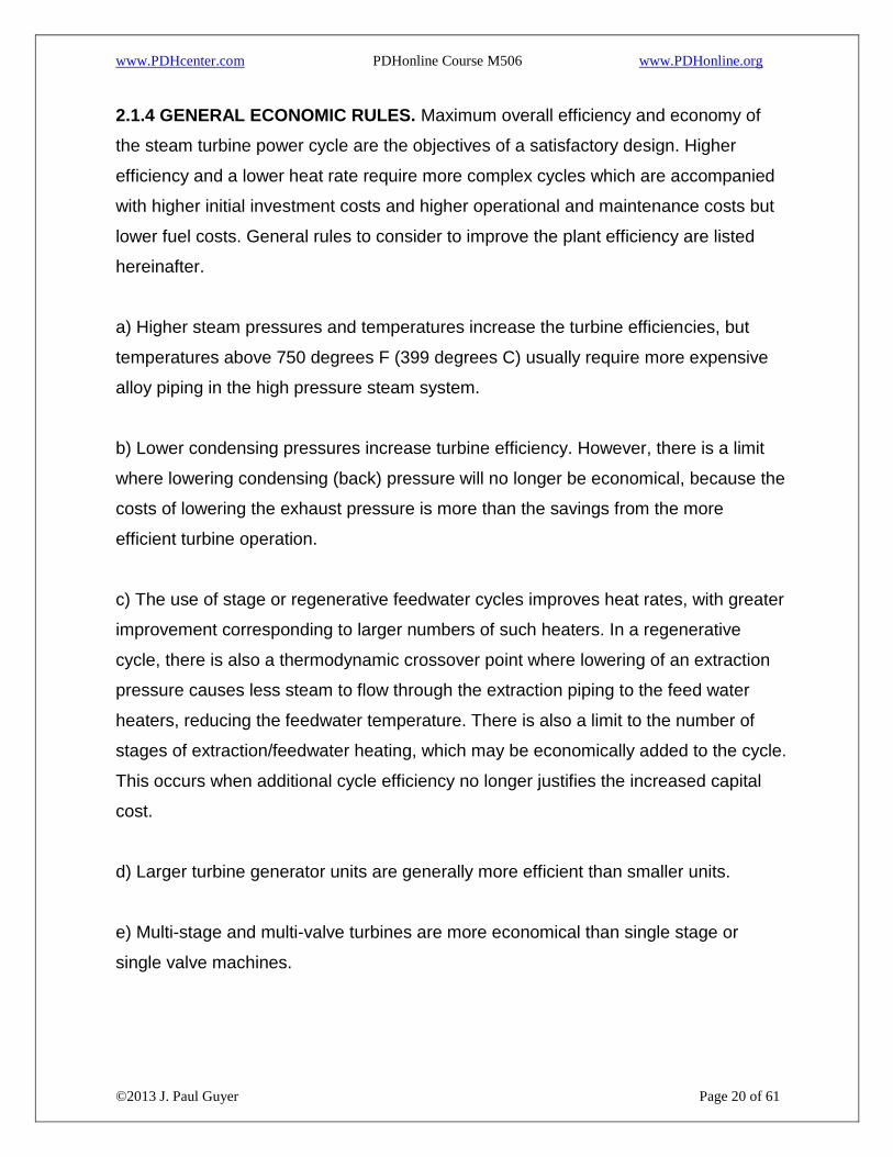
2.1.3.1 SIMPLE CONDENSING CYCLES. Straight condensing cycles or condensing
units with uncontrolled extractions are applicable to plants or situations where security
or isolation from public utility power supply is more important than lowest power cost.
Because of their higher heat rates and operating costs per unit output, it is not likely
that simple condensing cycles will be economically justified for some power plant
applications as compared with that associated with public utility purchased power
costs. A schematic diagram of an uncontrolled extraction-cycle is shown in Figure 1.
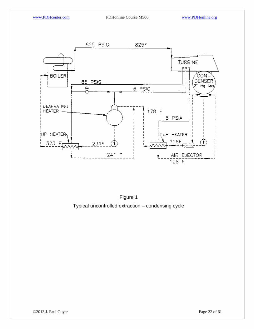
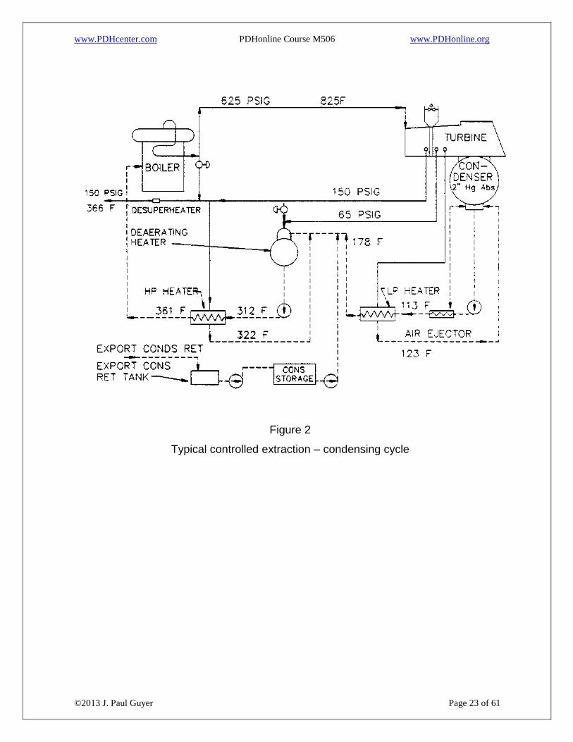
2.1.3.2 CONTROLLED EXTRACTION-CONDENSING CYCLES AND BACK
PRESSURE CYCLES. Back pressure and controlled extraction-condensing cycles are
attractive and applicable to a cogeneration plant, which is defined as a power plant
simultaneously supplying either electric power or mechanical energy and heat energy.
A schematic diagram of a controlled extraction-condensing cycle is shown in Figure 2.
A schematic diagram of a back pressure cycle is shown in Figure 3.
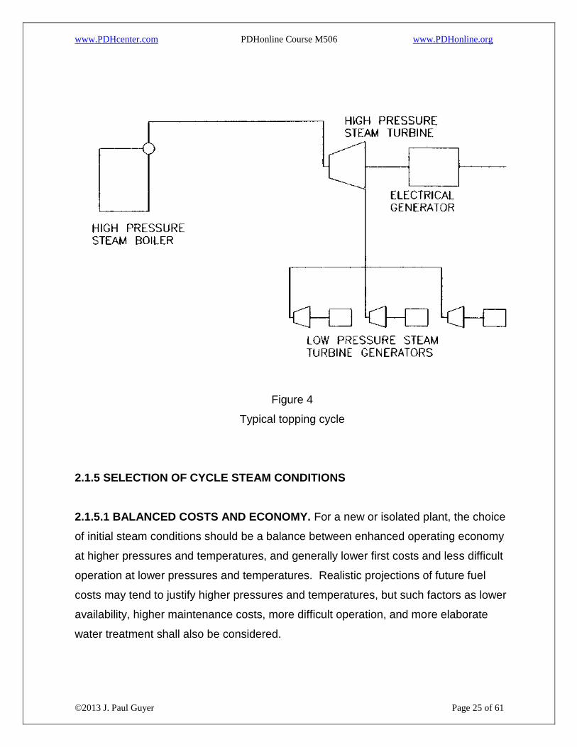
2.1.3.3 TOPPING CYCLE. A schematic diagram of a topping cycle is shown in Figure
4. The topping cycle consists of a high pressure steam boiler and turbine generator
with the high pressure turbine exhausting steam to one or more low pressure steam
turbine generators. High pressure topping turbines are usually installed as an addition
to an existing lower pressure steam electric plant.
Page 20
www.PDHcenter.com PDHonline Course M506 www.PDHonline.org
©2013 J. Paul Guyer Page 20 of 61
2.1.4 GENERAL ECONOMIC RULES. Maximum overall efficiency and economy of
the steam turbine power cycle are the objectives of a satisfactory design. Higher
efficiency and a lower heat rate require more complex cycles which are accompanied
with higher initial investment costs and higher operational and maintenance costs but
lower fuel costs. General rules to consider to improve the plant efficiency are listed
hereinafter.
a) Higher steam pressures and temperatures increase the turbine efficiencies, but
temperatures above 750 degrees F (399 degrees C) usually require more expensive
alloy piping in the high pressure steam system.
b) Lower condensing pressures increase turbine efficiency. However, there is a limit
where lowering condensing (back) pressure will no longer be economical, because the
costs of lowering the exhaust pressure is more than the savings from the more
efficient turbine operation.
c) The use of stage or regenerative feedwater cycles improves heat rates, with greater
improvement corresponding to larger numbers of such heaters. In a regenerative
cycle, there is also a thermodynamic crossover point where lowering of an extraction
pressure causes less steam to flow through the extraction piping to the feed water
heaters, reducing the feedwater temperature. There is also a limit to the number of
stages of extraction/feedwater heating, which may be economically added to the cycle.
This occurs when additional cycle efficiency no longer justifies the increased capital
cost.
d) Larger turbine generator units are generally more efficient than smaller units.
e) Multi-stage and multi-valve turbines are more economical than single stage or
single valve machines.
Page 21
www.PDHcenter.com PDHonline Course M506 www.PDHonline.org
©2013 J. Paul Guyer Page 21 of 61
f) Steam generators of more elaborate design and with heat saving accessory
equipment are more efficient.
Page 22
www.PDHcenter.com PDHonline Course M506 www.PDHonline.org
©2013 J. Paul Guyer Page 22 of 61
Figure 1
Typical uncontrolled extraction – condensing cycle
Page 23
www.PDHcenter.com PDHonline Course M506 www.PDHonline.org
©2013 J. Paul Guyer Page 23 of 61
Figure 2
Typical controlled extraction – condensing cycle
Page 24
www.PDHcenter.com PDHonline Course M506 www.PDHonline.org
©2013 J. Paul Guyer Page 24 of 61
Figure 3
Typical back pressure cycle
Page 25
www.PDHcenter.com PDHonline Course M506 www.PDHonline.org
©2013 J. Paul Guyer Page 25 of 61
Figure 4
Typical topping cycle
2.1.5 SELECTION OF CYCLE STEAM CONDITIONS
2.1.5.1 BALANCED COSTS AND ECONOMY. For a new or isolated plant, the choice
of initial steam conditions should be a balance between enhanced operating economy
at higher pressures and temperatures, and generally lower first costs and less difficult
operation at lower pressures and temperatures. Realistic projections of future fuel
costs may tend to justify higher pressures and temperatures, but such factors as lower
availability, higher maintenance costs, more difficult operation, and more elaborate
water treatment shall also be considered.
Page 26
www.PDHcenter.com PDHonline Course M506 www.PDHonline.org
©2013 J. Paul Guyer Page 26 of 61
2.1.5.2 EXTENSION OF EXISTING PLANT. Where a new steam power plant is to be
installed near an existing steam power or steam generation plant, careful
consideration shall be given to extending or paralleling the existing initial steam
generating conditions. If existing steam generators are simply not usable in the new
plant cycle, it may be appropriate to retire them or to retain them for emergency or
standby service only. If boilers are retained for standby service only, steps shall be
taken in the project design for protection against internal corrosion.
2.1.5.3 SPECIAL CONSIDERATIONS. Where the special circumstances of the
establishment to be served are significant factors in power cycle selection, the
following considerations may apply:
2.1.5.3.1 ELECTRICAL ISOLATION. Where the proposed plant is not to be
interconnected with any local electric utility service, the selection of a simpler, lower
pressure plant may be indicated for easier operation and better reliability.
2.1.5.3.2 GEOGRAPHIC ISOLATION. Plants to be installed at great distances from
sources of spare parts, maintenance services, and operating supplies may require
special consideration of simplified cycles, redundant capacity and equipment, and
highest practical reliability. Special maintenance tools and facilities may be required,
the cost of which would be affected by the basic cycle design.
2.1.5.3.3 WEATHER CONDITIONS. Plants to be installed under extreme weather
conditions require special consideration of weather protection, reliability, and
redundancy. Heat rejection requires special design consideration in either very hot or
very cold weather conditions. For arctic weather conditions, circulating hot water for
the heat distribution medium has many advantages over steam, and the use of an
antifreeze solution in lieu of pure water as a distribution medium should receive
consideration.
2.1.6 STEAM POWER PLANT ARRANGEMENT
Page 27
www.PDHcenter.com PDHonline Course M506 www.PDHonline.org
©2013 J. Paul Guyer Page 27 of 61
2.1.6.1 GENERAL. Small units utilize the transverse arrangement in the turbine
generator bay, while the larger utility units are very long and require end-to-end
arrangement of the turbine generators.
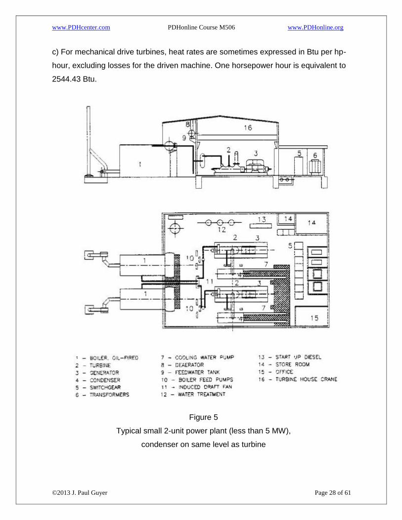
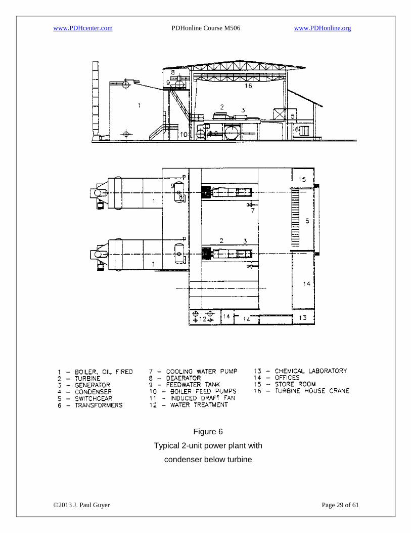
2.1.6.2 TYPICAL SMALL PLANTS. Figures 5 and 6 show typical transverse small
plant arrangements. Small units less than 5,000 kW may have the condensers at the
same level as the turbine generator for economy, as shown in Figure 5. Figure 7
indicates the critical turbine room bay clearances.
2.1.7 HEAT RATES. The final measure of turbine cycle efficiency is represented by
the turbine heat rate. It is determined from a heat balance of the cycle, which accounts
for all flow rates, pressures, temperatures, and enthalpies of steam, condensate, or
feedwater at all points of change in these thermodynamic properties. Heat rate is an
excellent measure of the fuel economy of power generation.
2.1.7.1 HEAT RATE UNITS AND DEFINITIONS. The economy or efficiency of a
steam power plant cycle is expressed in terms of heat rate, which is total thermal input
to the cycle divided by the electrical output of the units. Units are Btu/kWh.
a) Conversion to cycle efficiency, as the ratio of output to input energy, may be made
by dividing the heat content of one kWh, equivalent to 3412.14 Btu by the heat rate, as
defined. Efficiencies are seldom used to express overall plant or cycle performance,
although efficiencies of individual components, such as pumps or steam generators,
are commonly used.
b) Power cycle economy for particular plants or stations is sometimes expressed in
terms of pounds of steam per kilowatt hour, but such a parameter is not readily
comparable to other plants or cycles and omits steam generator efficiency.
Page 28
www.PDHcenter.com PDHonline Course M506 www.PDHonline.org
©2013 J. Paul Guyer Page 28 of 61
c) For mechanical drive turbines, heat rates are sometimes expressed in Btu per hp-
hour, excluding losses for the driven machine. One horsepower hour is equivalent to
2544.43 Btu.
Figure 5
Typical small 2-unit power plant (less than 5 MW),
condenser on same level as turbine
Page 29
www.PDHcenter.com PDHonline Course M506 www.PDHonline.org
©2013 J. Paul Guyer Page 29 of 61
Figure 6
Typical 2-unit power plant with
condenser below turbine
Page 30
www.PDHcenter.com PDHonline Course M506 www.PDHonline.org
©2013 J. Paul Guyer Page 30 of 61
Figure 7
Critical turbine room bay clearances
Page 31
www.PDHcenter.com PDHonline Course M506 www.PDHonline.org
©2013 J. Paul Guyer Page 31 of 61
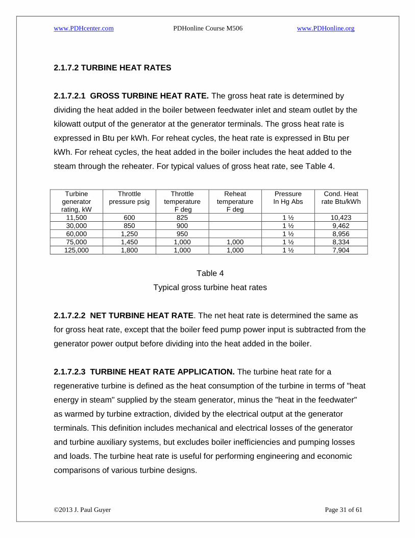
2.1.7.2 TURBINE HEAT RATES
2.1.7.2.1 GROSS TURBINE HEAT RATE. The gross heat rate is determined by
dividing the heat added in the boiler between feedwater inlet and steam outlet by the
kilowatt output of the generator at the generator terminals. The gross heat rate is
expressed in Btu per kWh. For reheat cycles, the heat rate is expressed in Btu per
kWh. For reheat cycles, the heat added in the boiler includes the heat added to the
steam through the reheater. For typical values of gross heat rate, see Table 4.
Turbine generator rating, kW
Throttle pressure psig
Throttle temperature
F deg
Reheat temperature
F deg
Pressure In Hg Abs
Cond. Heat rate Btu/kWh
11,500 600 825 1 ½ 10,423
30,000 850 900 1 ½ 9,462
60,000 1,250 950 1 ½ 8,956
75,000 1,450 1,000 1,000 1 ½ 8,334
125,000 1,800 1,000 1,000 1 ½ 7,904
Table 4
Typical gross turbine heat rates
2.1.7.2.2 NET TURBINE HEAT RATE. The net heat rate is determined the same as
for gross heat rate, except that the boiler feed pump power input is subtracted from the
generator power output before dividing into the heat added in the boiler.
2.1.7.2.3 TURBINE HEAT RATE APPLICATION. The turbine heat rate for a
regenerative turbine is defined as the heat consumption of the turbine in terms of "heat
energy in steam" supplied by the steam generator, minus the "heat in the feedwater"
as warmed by turbine extraction, divided by the electrical output at the generator
terminals. This definition includes mechanical and electrical losses of the generator
and turbine auxiliary systems, but excludes boiler inefficiencies and pumping losses
and loads. The turbine heat rate is useful for performing engineering and economic
comparisons of various turbine designs.
Page 32
www.PDHcenter.com PDHonline Course M506 www.PDHonline.org
©2013 J. Paul Guyer Page 32 of 61
2.1.7.3 PLANT HEAT RATES. Plant heat rates include inefficiencies and losses
external to the turbine generator, principally the inefficiencies of the steam generator
and piping systems; cycle auxiliary losses inherent in power required for pumps and
fans; and related energy uses such as for soot blowing, air compression, and similar
services.
2.1.7.3.1 GROSS PLANT HEAT RATE. This heat rate (Btu/kWh) is determined by
dividing the total heat energy (Btu/hour) in fuel added to the boiler by the kilowatt
output of the generator.
2.1.7.3.2 NET PLANT HEAT RATE. This heat rate is determined by dividing the total
fuel energy (Btu/hour) added to the boiler by the difference between power
(kilowatts/hour) generated and plant auxiliary electrical power consumed.
2.1.7.4 CYCLE PERFORMANCE. Both turbine and plant heat rates, as above, are
usually based on calculations of cycle performance at specified steady state loads and
well defined, optimum operating conditions. Such heat rates are seldom achieved in
practice except under controlled or test conditions.
2.1.7.5 LONG TERM AVERAGES. Plant operating heat rates are actual long term
average heat rates and include other such losses and energy uses as non-cycle
auxiliaries, plant lighting, air conditioning and heating, general water supply, startup
and shutdown losses, fuel deterioration losses, and related items. The gradual and
inevitable deterioration of equipment, and failure to operate at optimum conditions, are
reflected in plant operating heat rate data.
2.1.7.6 PLANT ECONOMY CALCULATIONS. Calculations, estimates, and
predictions of steam plant performance shall allow for all normal and expected losses
and loads and should, therefore, reflect predictions of monthly or annual net operating
heat rates and costs. Electric and district heating distribution losses are not usually
charged to the power plant but should be recognized and allowed for in capacity and
Page 33
www.PDHcenter.com PDHonline Course M506 www.PDHonline.org
©2013 J. Paul Guyer Page 33 of 61
cost analyses. The designer is required to develop and optimize a cycle heat balance
during the conceptual or preliminary design phase of the project. The heat balance
depicts, on a simplified flow diagram of the cycle, all significant fluid mass flow rates,
fluid pressures and temperatures, fluid enthalpies, electric power output, and
calculated cycle heat rates based on these factors. A heat balance is usually
developed for various increments of plant load such as 25, 50, 75, 100 percent and
VWO (valves, wide open). Computer programs have been developed which can
quickly optimize a particular cycle heat rate using iterative heat balance calculations.
Use of such a program should be considered.
2.1.8 STEAM RATES
2.1.8.1 THEORETICAL STEAM RATE. When the turbine throttle pressure and
temperature and the turbine exhaust pressure (or condensing pressure) are known,
the theoretical steam rate can be calculated based on a constant entropy expansion or
can be determined from published tables. See Theoretical Steam Rate Tables, The
American Society of Mechanical Engineers, 1969. See Table 5 for typical theoretical
steam rates.
Page 34
www.PDHcenter.com PDHonline Course M506 www.PDHonline.org
©2013 J. Paul Guyer Page 34 of 61
Pin, PSIG
Tin, F 100 Sat
200 Sat
250 550
400 750
600 825
850 900
1250 950
1450 1000
1600 1000
Exhaust, P
1” HGA 10.20 9.17 8.09 6.85 6.34 5.92 5.62 5.43 5.40
2” HGA 11.31 10.02 8.78 7.36 6.76 6.28 5.94 5.73 5.69
3” HGA 12.12 10.62 9.27 7.71 7.05 6.53 6.16 5.93 5.89
0 PSIG 22.73 17.52 14.57 11.19 9.82 8.81 8.10 7.72 7.62
5 PSIG 26.07 19.35 15.90 11.99 10.42 9.29 8.49 8.07 7.96
10 PSIG 29.52 21.10 17.15 12.71 10.96 9.71 8.83 8.38 8.26
15 PSIG 33.20 22.83 18.35 13.38 11.44 10.08 9.14 8.66 8.52
20 PSIG 37.17 24.56 19.53 14.02 11.90 10.43 9.42 8.91 8.76
25 PSIG 41.56 26.31 20.70 14.63 12.34 10.76 9.68 9.14 8.98
50 PSIG 74.80 35.99 26.75 17.56 14.31 12.22 10.80 10.15 9.94
100 PSIG 66.60 42.40 23.86 18.07 14.77 12.65 11.78 11.46
150 PSIG 71.80 31.93 22.15 17.33 14.35 13.26 12.79
200 PSIG 43.15 26.96 20.05 16.05 14.72 14.08
300 PSIG 40.65 26.53 19.66 17.74 16.70
400 PSIG 78.30 35.43 23.82 21.10 19.52
500 PSIG 49.03 28.87 25.03 22.69
600 PSIG 73.10 35.30 29.79 26.35
Table 5
Theoretical steam rates, lb/KWH
The equation for the theoretical steam rate is as follows:
TSR. = 3413/(h1 - h2) (eq 1)
where:
TSR. = theoretical steam rate of the turbine, lb/kWh
h1 = throttle enthalpy at the throttle pressure and temperature, Btu/lb
h2 = extraction or exhaust enthalpy at the exhaust pressure based on isentropic
expansion, Btu/1b.
2.1.8.2 TURBINE GENERATOR ENGINE EFFICIENCY. The engine efficiency is an
overall efficiency and includes the entire performance and mechanical and electrical
Page 35
www.PDHcenter.com PDHonline Course M506 www.PDHonline.org
©2013 J. Paul Guyer Page 35 of 61
losses of the turbine and generator. The engine efficiency can be calculated using the
following equation:
ne = (h1 - he)ntng/(h1 - h2) (eq 2)
where:
ne = Turbine generator engine efficiency
h1 and h2 = (see Equation 1)
he = Actual extraction or exhaust enthalpy, Btu/lb
nt = Turbine mechanical efficiency
ng = Generator efficiency
Engine efficiency is usually obtained from turbine generator manufacturers or their
literature. Therefore, it is not usually necessary to calculate engine efficiency.
2.1.8.3 ACTUAL STEAM RATE. The actual steam rate of a turbine can be determined
by dividing the actual throttle steam flow rate in pounds per hour by the actual
corresponding kilowatts, at the generator terminals, produced by that amount of
steam. The resulting steam rate is expressed in pounds of steam per kWh. The actual
steam rate can also be determined by dividing the theoretical steam rate by the engine
efficiency of the turbine generator.
ASR = TSR./ne (eq 3)
where:
ASR = actual steam rate of the turbine, lb/kWh.
2.2 COGENERATION IN STEAM POWER PLANTS. Cogeneration in a steam power
plant affects the design of the steam turbine relative to the type of cycle used, the
Page 36
www.PDHcenter.com PDHonline Course M506 www.PDHonline.org
©2013 J. Paul Guyer Page 36 of 61
exhaust or extraction pressures required, the loading of the steam turbine, and the
size of the steam turbine.
2.2.1 DEFINITION. In steam power plant practice, cogeneration normally describes an
arrangement whereby high pressure steam is passed through a turbine prime mover to
produce electrical power, and thence from the turbine exhaust (or extraction) opening
to a lower pressure steam (or heat) distribution system for general heating,
refrigeration, or process use.
2.2.2 COMMON MEDIUM. Steam power cycles are particularly applicable to
cogeneration situations because the actual cycle medium, steam, is also a convenient
medium for area distribution of heat.
a) The choice of the steam distribution pressure should be a balance between the
costs of distribution, which are slightly lower at high pressure, and the gain in electrical
power output by selection of a lower turbine exhaust or extraction pressure.
b) Often, the early selection of a relatively low steam distribution pressure is easily
accommodated in the design of distribution and utilization systems, whereas the hasty
selection of a relatively high steam distribution pressure may not be recognized as a
distinct economic penalty on the steam power plant cycle.
c) Hot water heat distribution may also be applicable as a district heating medium with
the hot water being cooled in the utilization equipment and returned to the power plant
for reheating in a heat exchange with exhaust (or extraction) steam.
2.2.3 RELATIVE ECONOMY. When the exhaust (or extraction) steam from a
cogeneration plant can be utilized for heating, refrigeration, or process purposes in
reasonable phase with the required electric power load, there is a marked economy of
fuel energy because the major condensing loss of the conventional steam power plant
(Rankine) cycle is avoided. If a good balance can be attained, up to 75 per cent of the
Page 37
www.PDHcenter.com PDHonline Course M506 www.PDHonline.org
©2013 J. Paul Guyer Page 37 of 61
total fuel energy can be utilized, as compared with about 40 percent for the best and
largest Rankine cycle plants and about 25 to 30 percent for small Rankine cycle
systems.
2.2.4 CYCLE TYPES. The two major steam power cogeneration cycles, which may be
combined in the same plant or establishment, are the back pressure and extraction-
condensing cycles.
2.2.4.1 BACK PRESSURE CYCLE. In a back pressure turbine, the entire flow to the
turbine is exhausted (or extracted) for heating steam use. This cycle is more effective
for heat economy and for relatively lower cost of turbine equipment, because the prime
mover is smaller and simpler and requires no condenser and circulating water system.
Back pressure turbine generators are limited in electrical output by the amount of
exhaust steam required by the heat load and are often governed by the exhaust steam
load. They, therefore, usually operate in electrical parallel with other generators.
2.2.4.2 EXTRACTION-CONDENSING CYCLE. Where the electrical demand does not
correspond to the heat demand, or where the electrical load must be carried at times
of very low (or zero) heat demand, then condensing-controlled extraction steam
turbine prime movers, as shown in Figure 2, may be applicable. Such a turbine is
arranged to carry a specified electrical capacity either by a simple condensing cycle or
a combination of extraction and condensing. While very flexible, the extraction
machine is relatively complicated, requires complete condensing and heat rejection
equipment, and must always pass a critical minimum flow of steam to its condenser to
cool the low pressure buckets.
2.2.5 CRITERIA FOR COGENERATION. For minimum economic feasibility,
cogeneration cycles will meet the following criteria:
Page 38
www.PDHcenter.com PDHonline Course M506 www.PDHonline.org
©2013 J. Paul Guyer Page 38 of 61
2.2.5.1 LOAD BALANCE. There should be a reasonably balanced relationship
between the peak and normal requirements for electric power and heat. The
peak/normal ratio should not exceed 2:1.
2.2.5.2 LOAD COINCIDENCE. There should be a fairly high coincidence, not less
than 70 percent, of time and quantity demands for electrical power and heat.
2.2.5.3 SIZE. While there is no absolute minimum size of steam power plant which can
be built for cogeneration, a conventional steam (cogeneration) plant will be practical
and economical only above some minimum size or capacity, below which other types
of cogeneration, diesel, or gas turbine become more economical and convenient.
2.2.5.4 DISTRIBUTION MEDIUM. Any cogeneration plant will be more effective and
economical if the heat distribution medium is chosen at the lowest possible steam
pressure or lowest possible hot water temperature. The power energy delivered by the
turbine is highest when the exhaust steam pressure is lowest. Substantial cycle
improvement can be made by selecting an exhaust steam pressure of 40 psig (276
kPa gage) rather than 125 psig (862 kPa gage), for example. Hot water heat
distribution should also be considered where practical or convenient, because hot
water temperatures of 200 to 240 degrees F (93 to 116 degrees C) can be delivered
with exhaust steam pressure as low as 20 to 50 psig (138 to 345 kPa gage). The
balance between distribution system and heat exchanger costs, and power cycle
effectiveness should be optimized.
2.3 TURBINE TYPES
2.3.1 CONDENSING TYPES
2.3.1.1 HIGH PRESSURE EXTRACTION TYPE. Turbines with throttle pressures
generally above 400 psig (2758 kPa gage) are considered high pressure machines;
however, the exact demarcation between high, intermediate, and low pressure
Page 39
www.PDHcenter.com PDHonline Course M506 www.PDHonline.org
©2013 J. Paul Guyer Page 39 of 61
turbines is not definite. Turbines built with provisions for extraction of steam from the
turbine at intermediate pressure points below the throttle pressure are called extraction
turbines. The extracted steam may be used for process systems, feed water heating,
and environmental heating. A typical cycle using a high pressure extraction type
turbine is shown in Figure 2.
2.3.1.2 HIGH PRESSURE NON-EXTRACTION TYPE. The high pressure non-
extraction type of turbine is basically the same as the extraction type described in
2.3.1.1 above, except no steam is extracted from the turbine. High pressure steam
enters the turbine throttle and expands through the turbine to the condenser. The
condenser pressure is comparable to that with high pressure extraction machines.
2.3.1.3 AUTOMATIC EXTRACTION TYPE. Automatic extraction turbines usually
operate with high pressure, high temperature throttle steam supply to a high pressure
turbine section. The exhaust pressure of the high pressure turbine is held constant by
means of automatic extraction gear (valve) that regulates the amount of steam passing
to the low pressure turbine. Single automatic extraction turbines provide steam at a
constant pressure from the automatic extraction opening, usually in the range of 50 to
150 psig (345 to 1034 kPa gage). Double automatic extraction turbines consist of a
high, intermediate, and low pressure turbine section and provide steam in the range of
50 to 150 psig (345 to 1034 kPa gage) at one automatic extraction opening and 10 to
15 psig (69 to 103 kPa gage) at the other automatic extraction opening. Automatic
extraction turbine generators operating automatically meet both automatic extraction
steam and electrical demands by adjusting the flow of steam through the low pressure
turbine. A typical automatic extraction cycle is shown in Figure 8. Automatic extraction
turbines may be either condensing (condenser pressure 1.0 to 4.0 inches of Hg Abs.)
or noncondensing (usually 5 to 15 psig (34 to 103 kPa gage) back pressure).
2.3.1.4 MIXED PRESSURE OR INDUCTION TYPE. The mixed pressure or induction
type turbine is supplied with steam to the throttle and also to other stages or sections
at a pressure lower than throttle pressure. This type of machine is also called an
Page 40
www.PDHcenter.com PDHonline Course M506 www.PDHonline.org
©2013 J. Paul Guyer Page 40 of 61
admission type. The steam admitted into the lower pressure openings may come from
old low pressure boilers, or it may be the excess from auxiliary equipment or
processes. The mixed pressure turbine is the same as an automatic extraction turbine
described in 2.3.1.3 above, except steam is admitted instead of extracted at the
automatic controlled opening.
2.3.1.5 LOW PRESSURE TYPE. Low pressure turbines are those with throttle
pressures generally below 400 psig (2758 kPa gage). However, the pressure dividing
point varies, depending on the manufacturer and type of turbine (industrial, mechanical
drive, etc.). The variations as described in 2.3.1.1, 2.3.1.2, and 2.3.1.3 above are also
applicable to low pressure turbines.
2.3.2 NONCONDENSING TYPES
2.3.2.1 SUPERPOSED OR TOPPING TYPE. Refer to para 2.1.3.3, and Figure 4 in
this publication for a description of topping turbine and cycle.
Page 41
www.PDHcenter.com PDHonline Course M506 www.PDHonline.org
©2013 J. Paul Guyer Page 41 of 61
Figure 8
Typical automatic extraction cycle
2.3.2.2 BACK PRESSURE TYPE. Back pressure turbines usually operate with high
pressure, high temperature throttle steam supply, and exhaust at steam pressures in
the range of 5 to 300 psig (34 to 2068 kPa gage). Un-controlled steam extraction
openings can be provided depending on throttle pressure and exhaust pressures. Two
methods of control are possible. One of the methods modulates the turbine steam flow
Page 42
www.PDHcenter.com PDHonline Course M506 www.PDHonline.org
©2013 J. Paul Guyer Page 42 of 61
to be such as to maintain the turbine exhaust pressure constant and, in the process,
generate as much electricity as possible from the steam passing through the turbine.
The amount of electricity generated, therefore, changes upward or downward with like
changes in steam demand from the turbine exhaust. A typical back pressure cycle is
shown in Figure 3. The other method of control allows the turbine steam flow to be
such as to provide whatever power is required from the turbine by driven equipment.
The turbine exhaust steam must then be used, at the rate flowing through the turbine,
by other steam consuming equipment or excess steam, if any, must be vented to the
atmosphere.
2.3.2.3 ATMOSPHERIC EXHAUST. Atmospheric exhaust is the term applied to
mechanical drive turbines which exhaust steam at pressures near atmospheric. These
turbines are used in power plants to drive equipment such as pumps and fans.
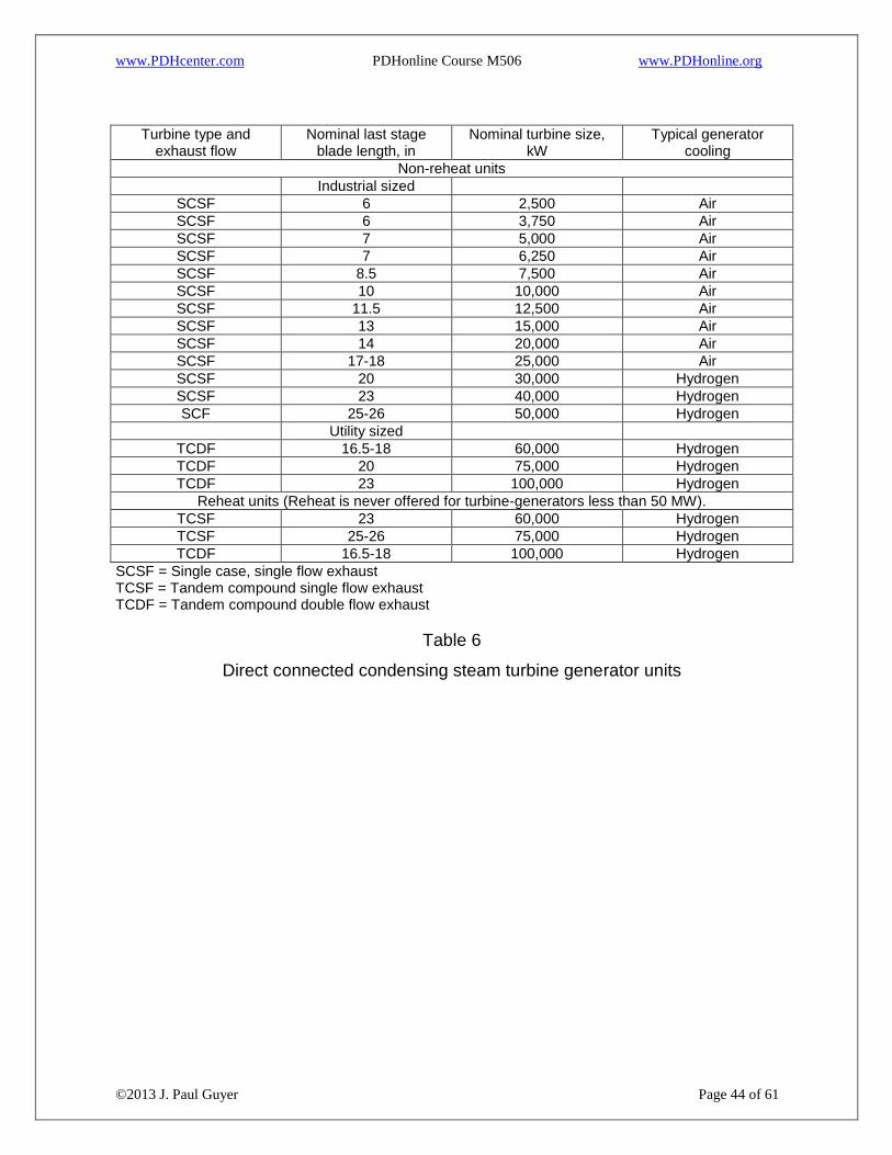
2.4 TURBINE GENERATOR SIZES. See Table 6 for nominal size and other
characteristic data for turbine generator units.
2.4.1 NONCONDENSING AND AUTOMATIC EXTRACTION TURBINES. The sizes of
turbine generators and types of generator cooling as shown in Table 9 generally apply
also to these types of turbines.
2.4.2 GEARED TURBINE GENERATOR UNITS. Geared turbine generator units
utilizing multistage mechanical drive turbines are available in sizes ranging generally
from 500 to 10,000 kW. Single stage geared units are available in sizes from 100 kW
to 3,000 kW. Multistage units are also available as single valve or multi-valve, which
allows further division of size range. Because of overlapping size range, the alternative
turbine valve and stage arrangements should be considered and economically
evaluated within the limits of their capabilities.
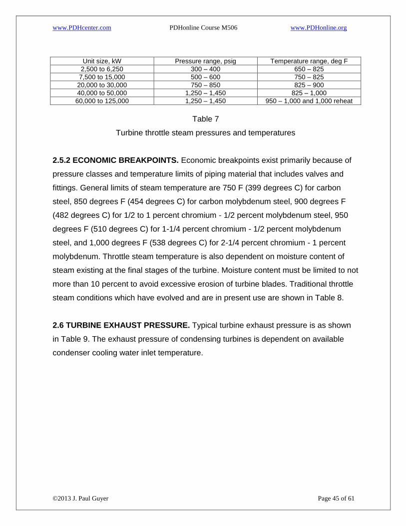
2.5 TURBINE THROTTLE PRESSURE AND TEMPERATURE. Small, single stage
turbines utilize throttle steam at pressures from less than 100 psig (689 kPa gage) and
Page 43
www.PDHcenter.com PDHonline Course M506 www.PDHonline.org
©2013 J. Paul Guyer Page 43 of 61
saturated temperatures up to 300 psig and 150 (66 degrees C) to 200 degrees F (93
degrees C) of superheat. Steam pressures and temperatures applicable to larger
multistage turbines are shown in Table 7.
2.5.1 SELECTION OF THROTTLE PRESSURE AND TEMPERATURE. The selection
of turbine throttle pressure and temperature is a matter of economic evaluation
involving performance of the turbine generator and cost of the unit including boiler,
piping, valves, and fittings.
Page 44
www.PDHcenter.com PDHonline Course M506 www.PDHonline.org
©2013 J. Paul Guyer Page 44 of 61
Turbine type and
exhaust flow Nominal last stage
blade length, in Nominal turbine size,
kW Typical generator
cooling
Non-reheat units
Industrial sized
SCSF 6 2,500 Air
SCSF 6 3,750 Air
SCSF 7 5,000 Air
SCSF 7 6,250 Air
SCSF 8.5 7,500 Air
SCSF 10 10,000 Air
SCSF 11.5 12,500 Air
SCSF 13 15,000 Air
SCSF 14 20,000 Air
SCSF 17-18 25,000 Air
SCSF 20 30,000 Hydrogen
SCSF 23 40,000 Hydrogen
SCF 25-26 50,000 Hydrogen
Utility sized
TCDF 16.5-18 60,000 Hydrogen
TCDF 20 75,000 Hydrogen
TCDF 23 100,000 Hydrogen
Reheat units (Reheat is never offered for turbine-generators less than 50 MW).
TCSF 23 60,000 Hydrogen
TCSF 25-26 75,000 Hydrogen
TCDF 16.5-18 100,000 Hydrogen
SCSF = Single case, single flow exhaust TCSF = Tandem compound single flow exhaust TCDF = Tandem compound double flow exhaust
Table 6
Direct connected condensing steam turbine generator units
Page 45
www.PDHcenter.com PDHonline Course M506 www.PDHonline.org
©2013 J. Paul Guyer Page 45 of 61
Unit size, kW Pressure range, psig Temperature range, deg F
2,500 to 6,250 300 – 400 650 – 825
7,500 to 15,000 500 – 600 750 – 825
20,000 to 30,000 750 – 850 825 – 900
40,000 to 50,000 1,250 – 1,450 825 – 1,000
60,000 to 125,000 1,250 – 1,450 950 – 1,000 and 1,000 reheat
Table 7
Turbine throttle steam pressures and temperatures
2.5.2 ECONOMIC BREAKPOINTS. Economic breakpoints exist primarily because of
pressure classes and temperature limits of piping material that includes valves and
fittings. General limits of steam temperature are 750 F (399 degrees C) for carbon
steel, 850 degrees F (454 degrees C) for carbon molybdenum steel, 900 degrees F
(482 degrees C) for 1/2 to 1 percent chromium - 1/2 percent molybdenum steel, 950
degrees F (510 degrees C) for 1-1/4 percent chromium - 1/2 percent molybdenum
steel, and 1,000 degrees F (538 degrees C) for 2-1/4 percent chromium - 1 percent
molybdenum. Throttle steam temperature is also dependent on moisture content of
steam existing at the final stages of the turbine. Moisture content must be limited to not
more than 10 percent to avoid excessive erosion of turbine blades. Traditional throttle
steam conditions which have evolved and are in present use are shown in Table 8.
2.6 TURBINE EXHAUST PRESSURE. Typical turbine exhaust pressure is as shown
in Table 9. The exhaust pressure of condensing turbines is dependent on available
condenser cooling water inlet temperature.
Page 46
www.PDHcenter.com PDHonline Course M506 www.PDHonline.org
©2013 J. Paul Guyer Page 46 of 61
Pressure, psig Temperature, degrees F
250 500 or 550
400 650 or 750
600 750 or 825
850 825 or 900
1,250 900 or 950
1,450 950 or 1,000
1600 1,000
Table 8
Typical turbine throttle steam pressure-temperature conditions
Turbine type Condensing, In Hg Abs Non-condensing, psig
Multivalve multistage 0.5 – 4.5 0 – 300
Superposed (topping) 200 – 600
Single valve multistage 1.5 – 4.0 0 – 300
Single valve single stage 2.5 – 3.0 1 – 100
Back pressure 5 – 300
Atmospheric pressure 0 - 50
Table 9
Typical turbine exhaust pressure
2.7 LUBRICATING OIL SYSTEMS
2.7.1 SINGLE STAGE TURBINES. The lubricating oil system for small, single stage
turbines is self-contained, usually consisting of water jacketed, water-cooled, rotating
ring-oiled bearings.
2.7.2 MULTISTAGE TURBINES. Multistage turbines require a separate pressure
lubricating oil system consisting of oil reservoir, bearing oil pumps, oil coolers,
pressure controls, and accessories.
a) The oil reservoir's capacity shall provide a 5 to 10 minute oil retention time based on
the time for a complete circuit of all the oil through the bearings.
Page 47
www.PDHcenter.com PDHonline Course M506 www.PDHonline.org
©2013 J. Paul Guyer Page 47 of 61
b) Bearing oil pump types and arrangement are determined from turbine generator
manufacturers' requirements. Turbine generators should be supplied with a main oil
pump integral on the turbine shaft. This arrangement is provided with one or more
separate auxiliary oil pumps for startup and emergency backup service. At least one of
the auxiliary oil pumps shall be separately steam turbine driven or DC motor driven.
For some hydrogen cooled generators, the bearing oil and hydrogen seal oil are
served from the same pumps.
c) Where separate oil coolers are necessary, two full capacity, water cooled oil coolers
shall be used. Turbine generator manufacturers' standard design for oil coolers is
usually based on a supply of fresh cooling water at 95 degrees F (35 degrees C) at
125 psig (862 kPa gage). These design conditions shall be modified, if necessary, to
accommodate actual cooling water supply conditions. Standard tube material is
usually inhibited admiralty or 90-10 copper-nickel. Other tube materials are available,
including 70-30 copper-nickel, aluminum-brass, arsenical copper, and stainless steel.
2.7.3 OIL PURIFIERS. Where a separate turbine oil reservoir and oil coolers are used,
a continuous bypass purification system with a minimum flow rate per hour equal to 10
percent of the turbine oil capacity shall be used. Refer to ASME Standard LOS-1M,
ASTM-ASME-NEMA Recommended Practices for the Cleaning, Flushing, and
Purification of Steam and Gas Turbine Lubricating Systems. The purification system
shall be either one of the following types.
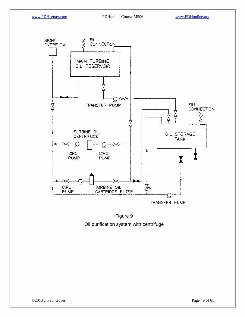
2.7.3.1 CENTRIFUGE WITH BYPASS PARTICLE SIZE FILTER. See Figure 9 for
arrangement of equipment. Because of the additives contained in turbine oils, careful
selection of the purification equipment is required to avoid the possibility of additive
removal by use of certain types of purification equipment such as clay filters or heat
and vacuum units. Both centrifuge and particle size filters are suitable for turbine oil
purification. Particle filters are generally sized for not less than 5 microns to avoid
removal of silicone foam inhibitors if present in the turbine oil used. The centrifuge is
used periodically for water removal from the turbine oil. The particle filter, usually of
Page 48
www.PDHcenter.com PDHonline Course M506 www.PDHonline.org
©2013 J. Paul Guyer Page 48 of 61
the cellulose cartridge type, is used continuously except during times the centrifuge is
used.
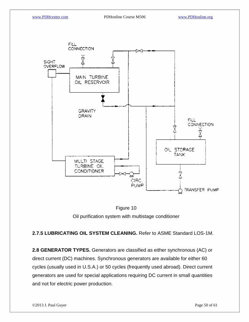
2.7.3.2 MULTISTAGE OIL CONDITIONER. See Figure 10 for arrangement of
equipment. The typical multistage conditioner consists of three stages: a precipitation
compartment where gross free water is removed by detention time and smaller
droplets are coalesced on hydrophobic screens, a gravity filtration compartment
containing a number of cloth-covered filter elements, and a storage compartment
which contains a polishing filter consisting of multiple cellulose cartridge filter
elements. The circulating pump receives oil from the storage compartment and pumps
the oil through the polishing filter and back to the turbine oil reservoir. The storage
compartment must be sized to contain the flowback oil quantity contained in the
turbine generator bearings and oil supply piping. The oil conditioner in this type of
purification system operates continuously.
2.7.4 LUBRICATING OIL STORAGE TANKS. As a minimum, provide one storage
tank and one oil transfer pump. The storage tank capacity should be equal to, or
greater than the largest turbine oil reservoir. The transfer pump is used to transfer oil
between the turbine oil reservoir and the storage tank. The single tank can be used to
receive oil from, or return oil to the turbine oil reservoir. Usually a separate portable oil
filter press is used for oil purification of used oil held in the storage tank. Two storage
tanks can be provided when separate tanks are desired for separate storage of clean
and used oil. This latter arrangement can also be satisfied by use of a two
compartment single tank. Only one set of storage tanks and associated transfer pump
is needed per plant. However, it may be necessary to provide an additional oil transfer
pump by each turbine oil reservoir, depending on plant arrangement.
Page 49
www.PDHcenter.com PDHonline Course M506 www.PDHonline.org
©2013 J. Paul Guyer Page 49 of 61
Figure 9
Oil purification system with centrifuge
Page 50
www.PDHcenter.com PDHonline Course M506 www.PDHonline.org
©2013 J. Paul Guyer Page 50 of 61
Figure 10
Oil purification system with multistage conditioner
2.7.5 LUBRICATING OIL SYSTEM CLEANING. Refer to ASME Standard LOS-1M.
2.8 GENERATOR TYPES. Generators are classified as either synchronous (AC) or
direct current (DC) machines. Synchronous generators are available for either 60
cycles (usually used in U.S.A.) or 50 cycles (frequently used abroad). Direct current
generators are used for special applications requiring DC current in small quantities
and not for electric power production.
Page 51
www.PDHcenter.com PDHonline Course M506 www.PDHonline.org
©2013 J. Paul Guyer Page 51 of 61
2.9 GENERATOR COOLING
2.9.1 SELF VENTILATION. Generators, approximately 2,000 kVA and smaller, are air
cooled by drawing air through the generator by means of a shaft-mounted propeller
fan.
2.9.2 AIR COOLED. Generators, approximately 2,500 kVA to 25,000 kVA, are air
cooled with water cooling of air coolers (water-to-air heat exchangers) located either
horizontally or vertically within the generator casing. Coolers of standard design are
typically rated for 95 degrees F (35 degrees C) cooling water at a maximum pressure
of 125 psig (862 kPa gage) and supplied with 5/8-inch minimum 18 Birmingham wire
gage (BWG) inhibited admiralty or 90-10 copper-nickel tubes. Design pressure of 300
psig (2068 kPa gage) can be obtained as an alternate. Also, alternate tube materials
such as aluminum-brass, 70-30 copper-nickel, or stainless steel are available.
2.9.3 HYDROGEN COOLED. Generators, approximately 30,000 kVA and larger, are
hydrogen cooled by means of hydrogen to air heat exchangers. The heat exchangers
are similar in location and design to those for air-cooled generators. Hydrogen
pressure in the generator casing is typically 30 psig (207 kPa gage).
2.10 TURBINE GENERATOR CONTROL. For turbine generator control description,
see the technical literature.
2.11 TURNING GEAR. In order to thermally stabilize turbine rotors and avoid rotor
warpage, the rotors of turbine generators size 12,500 kW and larger are rotated by a
motor-driven turning gear at a speed of approximately 5 rpm immediately upon taking
the turbine off the line. The rotation of the turbine generator rotor by the turning gear is
continued through a period of several hours to several days, depending on the size of
the turbine and the initial throttle temperature, until the turbine shaft is stabilized. The
turning gear and turbine generator rotor are then stopped until the turbine generator is
Page 52
www.PDHcenter.com PDHonline Course M506 www.PDHonline.org
©2013 J. Paul Guyer Page 52 of 61
about to be again placed in service. Before being placed in service, the turbine
generator rotor is again stabilized by turning gear rotation for several hours to several
days, depending on the turbine size. Turbine generators smaller than 12,500 kW are
not normally supplied with a turning gear, since the normal throttle steam temperature
is such that a turning gear is not necessary. However, should a turbine be selected for
operation at higher than usual throttle steam temperature, a turning gear would be
supplied. During turning gear operation, the turbine generator bearings are lubricated
by use of either the main bearing oil pump or a separate turning gear oil pump,
depending on size and manufacturer of the turbine generator.
2.12 TURBINE GENERATOR FOUNDATIONS. Turbine generator foundations shall
be designed in accordance with the technical literature.
2.13 AUXILIARY EQUIPMENT. For description of steam jet air ejectors, mechanical
air exhausters, and steam operated hogging ejectors, see the technical literature.
2.14 INSTALLATION. Instructions for turbine generator installation are definitive for
each machine and for each manufacturer. For turbine generators, 2,500 kW and
larger, these instructions shall be specially prepared for each machine by the turbine
generator manufacturer and copies (usually up to 25 copies) shall be issued to the
purchaser.
The purchase price of a turbine generator shall include technical installation, start-up,
and test supervision furnished by the manufacturer at the site of installation.
2.15 CLEANUP, STARTUP, AND TESTING
2.15.1 PIPE CLEANING
2.15.1.1 BOILER CHEMICAL BOIL OUT. Chemical or acid cleaning is the quickest
and most satisfactory method for the removal of water side deposits. Competent
chemical supervision should be provided, supplemented by consultants on boiler-
Page 53
www.PDHcenter.com PDHonline Course M506 www.PDHonline.org
©2013 J. Paul Guyer Page 53 of 61
water and scale problems during the chemical cleaning process. In general, four steps
are required in a complete chemical cleaning process for a boiler.
a) The internal heating surfaces are washed with an acid solvent containing a proper
inhibitor to dissolve the deposits completely or partially and to disintegrate them.
b) Clean water is used to flush out loose deposits, solvent adhering to the surface, and
soluble iron salts. Any corrosive or explosive gases that may have formed in the unit
are displaced.
c) The unit is treated to neutralize and "passivate" the heating surfaces. The
passivation treatment produces a passive surface or forms a very thin protective film
on ferrous surfaces so that formation of "after-rust" on freshly cleaned surfaces is
prevented.
d) The unit is flushed with clean water as a final rinse to remove any remaining loose
deposits. The two generally accepted methods in chemical cleaning are continuous
circulation and soaking.
e) Continuous Circulation. In the circulation method, after filling the unit, the hot
solvent is recirculated until cleaning is completed. Samples of the return solvent are
tested periodically during the cleaning. Cleaning is considered complete when the acid
strength and the iron content of the returned solvent reach equilibrium indicating that
no further reaction with the deposits is taking place. The circulation method is
particularly suitable for cleaning once-through boilers, superheaters, and economizers
with positive liquid flow paths to assure circulation of the solvent through all parts of
the unit.
f) Soaking. In cleaning by the soaking method after filling with the hot solvent, the unit
is allowed to soak for a period of four to eight hours, depending on deposit conditions.
To assure complete removal of deposits, the acid strength of the solvent must be
Page 54
www.PDHcenter.com PDHonline Course M506 www.PDHonline.org
©2013 J. Paul Guyer Page 54 of 61
somewhat greater than that required by the actual conditions, since, unlike the
circulation method, control testing during the course of the cleaning is not conclusive,
because samples of solvent drawn from convenient locations may not truly represent
conditions in all parts of the unit. The soaking method is preferable for cleaning units
where definite liquid distribution to all circuits by the circulation method is not possible
without the use of many chemical inlet connections or where circulation through all
circuits at an appreciable rate cannot be assured, except by using a circulating pump
of impractical size.
2.15.1.2 MAIN STEAM BLOWOUT. The main steam lines, reheat steam lines,
auxiliary steam lines from cold reheat and auxiliary boiler, and all main turbine seal
steam lines shall be blown with steam after erection and chemical cleaning until all
visible signs of mill scale, sand, rust, and other foreign substances are blown free.
Cover plates and internals for the main steam stop valves, reheat stop, and intercept
valves, shall be removed. Blanking fixtures, temporary cover plates, temporary vent
and drain piping, and temporary hangers and braces to make the systems safe during
the blowing operation shall be installed. After blowing, all temporary blanking fixtures,
cover plates, vent and drain piping, valves, hangers, and braces shall be removed.
The strainers, valve internals, and cover plates shall be reinstalled. The piping
systems, strainers, and valves shall be restored to a state of readiness for plant
operation.
2.15.1.2.1 TEMPORARY PIPING. Temporary piping shall be installed at the inlet to
the main turbine and the boiler feed pump turbine to facilitate blowout of the steam to
the outdoors. Temporary piping shall be designed in accordance with the requirements
of the Power Piping Code, ANSI/ASME B31.1. The temporary piping and valves shall
be sized to obtain a cleaning ratio of 1.0 or greater in all permanent piping to be
cleaned. The cleanout ratio is determined using the following equation.
R = (Qc/Qm)2 x [(Pv)c/(Pv)m x (Pm/Pc) (eq 4)
Page 55
www.PDHcenter.com PDHonline Course M506 www.PDHonline.org
©2013 J. Paul Guyer Page 55 of 61
where
R = cleaning ratio
Qc = flow during cleaning, lb/hr
Qm = Maximum load flow, lb/hr
(Pv)c = pressure-specific volume product during cleaning at boiler outlet, ft3/in2
(Pv)m = pressure-specific volume product at maximum load flow at boiler outlet, ft3/in2
Pm = pressure at maximum load flow at boiler outlet, psia
Pc = Pressure during cleaning at boiler outlet, psia
This design procedure is applicable to fossil fuel-fired power plants, and is written
specifically for drum (controlled circulation) type boilers but may be adapted to once-
through (combined circulation) type boilers by making appropriate modifications to the
procedure. The same basic concepts for cleaning piping systems apply to all boiler
types.
2.15.1.2.2 BLOWOUT SEQUENCE. Boiler and turbine manufacturers provide a
recommended blowout sequence for the main and reheat steam lines. The most
satisfactory method for cleaning installed piping is to utilize the following cleaning
cycle:
(1) Rapid heating (thermal shock helps remove adhered particles).
(2) High velocity steam blowout to atmosphere.
(3) Thermal cool down prior to next cycle.
The above cycle is repeated until the steam emerging from the blowdown piping is
observed to be clean.
2.15.1.3 INSTALLATION OF TEMPORARY STRAINERS. Temporary strainers shall
be installed in the piping system at the suction of the condensate and boiler feed
pumps to facilitate removal of debris within the piping systems resulting from the
Page 56
www.PDHcenter.com PDHonline Course M506 www.PDHonline.org
©2013 J. Paul Guyer Page 56 of 61
installation procedures. The strainers shall be cleaned during the course of all flushing
and chemical cleaning operations. The temporary strainers shall be removed after
completion of the flushing and chemical cleaning procedures.
2.15.1.4 CONDENSER CLEANING. All piping systems with lines to the condenser
should be completed and the lines to the condenser flushed with service water. Lines
not having spray pipes in the condenser may be flushed into the condenser. Those
with spray pipes should be flushed before making the connection to the condenser.
Clean the interior of the condenser and hot well by vacuuming and by washing with an
alkaline solution and flushing with hot water. Remove all debris. Open the condensate
pump suction strainer drain valves and flush the pump suction piping. Prevent flush
water from entering the pumps. Clean the pump suction strainers. 5.15.1.5
Condensate System Chemical Cleaning. Systems to be acid and alkaline cleaned are
the condensate piping from condensate pump to deaerator discharge, boiler feedwater
piping from deaerator to economizer inlet, feedwater heater tube sides, air preheat
system piping, and chemical cleaning pump suction and discharge piping. Systems to
be alkaline cleaned only, are the feedwater heater shell sides, building heating heat
exchanger shell sides, and the feedwater heater drain piping. The chemicals and
concentrations for alkaline cleaning are 1000 mg/L disodium phosphate, 2,000 mg/L
trisodium phosphate, non-foaming wetting agent as required, and foam inhibitors as
required. The chemicals and concentrations for acid cleaning are 2.0 percent
hydroxyacetic acid, 1.0 percent formic acid, 0.25 percent ammonium bifluoride, and
foaming inhibitors and wetting agents as required.
2.15.1.4.1 DEAERATOR CLEANING. Prior to installing the trays in the deaerator and
as close to unit start-up as is feasible, the interior surfaces of the deaerator and
deaerator storage tank shall be thoroughly cleaned to remove all preservative coatings
and debris. Cleaning shall be accomplished by washing with an alkaline service water
solution and flushing with hot service water. The final rinse shall be with demineralized
water. After cleaning and rinsing, the deaerator and deaerator storage tank shall be
protected from corrosion by filling with treated demineralized water.
Page 57
www.PDHcenter.com PDHonline Course M506 www.PDHonline.org
©2013 J. Paul Guyer Page 57 of 61
2.15.1.4.2 CYCLE MAKEUP AND STORAGE SYSTEM. The cycle makeup and
storage system, condensate storage tank, and demineralized water storage tank shall
be flushed and rinsed with service water. The water storage tanks should require only
a general hose washing. The makeup water system should be flushed until the flush
water is clear. After the service water flush, the cycle makeup and storage system
shall be flushed with demineralized water until the flushing water has a clarity equal to
that from the demineralizer.
2.15.1.4.3 CONDENSATE-FEEDWATER AND AIR PREHEAT SYSTEMS. The
condensate-feedwater and air preheat systems (if any) shall be flushed with service
water. The condensate pumps shall be used for the service water flushing operations.
Normal water level in the condenser should be maintained during the service water
flushing operation by making up through the temporary service water fill line. After the
service water flush, the condensate-feedwater and air preheat systems shall be
flushed with demineralized water. After the demineralized water flush, the
condensate-feedwater and air preheat systems shall be drained and refilled with
demineralized water.
2.15.1.4.4 ALKALINE CLEANING. The condensate-feedwater and air preheat water
systems shall be alkaline cleaned by injecting the alkaline solution into circulating
treated water, preheated to 200 degrees F (93.3 degrees C) by steam injection, until
the desired concentrations are established. The alkaline solution should be circulated
for a minimum of 24 hours with samples taken during the circulation period. The
samples should be analyzed for phosphate concentration and evidence of free oil. The
feedwater heaters and drain piping shall be alkaline cleaned by soaking with hot
alkaline cleaning solution in conjunction with the condensate-feedwater and air
preheat water system alkaline cleaning. The heater shells and drain piping should be
drained once every six hours during the circulation of the alkaline cleaning solution
through the condensate feedwater and air preheat water systems. After the alkaline
Page 58
www.PDHcenter.com PDHonline Course M506 www.PDHonline.org
©2013 J. Paul Guyer Page 58 of 61
cleaning is completed, flush the condensate-feedwater, air preheat water, feedwater
heater, and drain piping systems with demineralized water.
2.15.1.4.5 ACID CLEANING. Acid cleaning of the condensate feedwater and air
preheat water systems shall be similar to the alkaline cleaning, except that the
circulation period shall only be six hours. The condensate-feedwater and air preheat
water system shall be heated to 200 degrees F (93 degrees C) and hydrazine and
ammonia injected into the circulating water to neutralize the acid solution. The systems
shall then be flushed with demineralized water until all traces of acid are removed.
2.15.1.6 TURBINE LUBE OIL FLUSH AND RECIRCULATION. The lubricating and
seal oil systems of the turbine generator shall be cleaned as recommended by the
manufacturer. Oil samples shall be tested to determine contamination levels. The
cleaning shall be a cold flushing of the system and cleaning of the oil reservoir. This
shall be followed by cycling of circulating hot and cold oil until the system is clean.
2.15.2 EQUIPMENT STARTUP
2.15.2.1 PRELIMINARY CHECKS. Preliminary checks and inspection, and any
required corrective work shall be performed on all equipment in accordance with the
equipment manufacturer's recommendations.
2.15.2.1.1 SHAFT ALIGNMENT. All bearings, shafts, and other moving parts shall be
checked for proper alignment.
2.15.2.1.2 LINKAGE ALIGNMENT. Manual set of all linkages shall be performed,
ensuring open and close limit adjustment. Operational linkage adjustment shall be
performed as required.
2.15.2.1.3 SAFETY EQUIPMENT. All coupling guards, belt guards, and other
personnel safety items shall be installed.
Page 59
www.PDHcenter.com PDHonline Course M506 www.PDHonline.org
©2013 J. Paul Guyer Page 59 of 61
2.15.2.1.4 PIPING. All power actuated valves shall be checked for correct valve action
and seating and the actuators and converters shall be given initial adjustment. All
manual valves shall be operated to ensure correct operation and seating. All safety
valves shall be checked for correct settings. All piping shall be nondestructively
tested, hydrostatically tested, leak tested, or air tested, as applicable, and shall be
flushed or blown clean. All temporary shipping braces, blocks, or tie rods shall be
removed from expansion joints. All spring type pipe hangers shall be checked for
proper cold settings.
2.15.2.1.5 PITS. All pump suction pits shall be free of trash.
2.15.2.1.6 LUBRICATION. Each lubricating oil system shall be flushed and the filters
inspected. All oil tanks, reservoirs, gear cases, and constant level type oilers shall be
checked for proper oil levels. All points requiring manual lubrication shall be greased
or oiled as required.
2.15.2.1.7 BELTS, PULLEYS, AND SHEAVES. All belts, pulleys, and sheaves shall
be checked for correct alignment and belt tension.
2.15.2.1.8 COOLING AND SEALING WATER. All cooling and sealing water supplies
shall be flushed and checked for proper operation.
2.15.2.1.9 PUMP SUCTION STRAINERS. All pump suction strainers shall be
installed.
2.15.2.1.10 STUFFING BOXES AND PACKING. All stuffing boxes shall be checked
for correct takeup on the packing.
2.15.2.1.11 MECHANICAL SEALS. All mechanical seals shall be removed as
required to ensure clean sealing surfaces prior to starting. Seal water piping shall be
Page 60
www.PDHcenter.com PDHonline Course M506 www.PDHonline.org
©2013 J. Paul Guyer Page 60 of 61
cleaned to the extent necessary to ensure no face contamination. Seal adjustments
shall be performed as required by the manufacturer.
2.15.2.1.12 TANKS AND VESSELS. All tanks and vessels shall be thoroughly
inspected internally before securing.
2.15.2.2 INITIAL PLANT STARTUP. The following steps shall be followed for plant
startup:
Operate demineralizer and fill condensate storage/return tank.
Fill boiler, deaerator, and condenser.
Start boiler feed pumps.
Warm up boiler using manufacturer's recommendations.
Start cooling water system pumps.
Start condensate pumps.
Start condenser exhauster (air ejectors).
Start turbine lubricating oil system.
Roll turbine using manufacturer's startup procedures.
2.15.3 TESTING. For testing requirements, see the technical literature.
2.16 OPERATION
2.16.1 TRIAL OPERATION. After all preliminary checks and inspections are
completed, each piece of equipment shall be given a trial operation. Trial operation of
all equipment and systems shall extend over such period of time as is required to
reveal any equipment weaknesses in bearings, cooling systems, heat exchangers, and
other such components, or any performance deficiencies which may later handicap the
operation of main systems and the complete plant. All rotating equipment shall be
checked for overheating, noise, vibration, and any other conditions which would tend
to shorten the life of the equipment.
Page 61
www.PDHcenter.com PDHonline Course M506 www.PDHonline.org
©2013 J. Paul Guyer Page 61 of 61
2.16.2 MAIN SYSTEM OPERATION. Main systems should be trial operated and
tested after each individual piece of equipment has been trial operated and ready for
operation. All functional and operational testing of protective interlocking, automatic
controls, instrumentation, alarm systems, and all other field testing should be
conducted during initial plant startup. All piping should be visually inspected for leaks,
improper support adjustment, interferences, excessive vibration, and other abnormal
conditions. Steam traps should be verified for proper operation and integral strainers
cleaned.
2.16.3 OPERATION CONTROL. A system of control to protect personnel and
equipment as the permanent plant equipment and systems are completed and capable
of energization, pressurization, or being operated, should be established. The system
should consist of placing appropriate tags on all equipment and system components.
Tags should indicate status and the mandatory clearances required from designated
personnel to operate, pressurize, energize, or remove from service such equipment or
systems. The controls established should encompass the following phases.
2.16.3.1 EQUIPMENT OR SYSTEMS COMPLETED to the point where they may be
energized, pressurized, or operated, but not yet checked out, shall be tagged. The
sources of power or pressure shall be turned off and tagged.
2.16.3.2 EQUIPMENT AND SYSTEMS RELEASED for preoperational check-out
shall be so tagged. When a request to remove from service is made, all controls and
sources of power or pressure shall be tagged out and shall not be operated under any
circumstances.