Page 1
An Introduction to Water Cooling Towers Course No: M02-054
Credit: 2 PDH
J. Paul Guyer, P.E., R.A., Fellow ASCE, Fellow AEI
Continuing Education and Development, Inc. 9 Greyridge Farm Court Stony Point, NY 10980 P: (877) 322-5800 F: (877) 322-4774 [email protected]
Page 2
J. Paul Guyer, P.E., R.A. Editor Paul Guyer is a registered civil engineer, mechanical engineer, fire protection engineer and architect with 35 years of experience designing buildings and related infrastructure. For an additional 9 years he was a principal staff advisor to the California Legislature on capital outlay and infrastructure issues. He is a graduate of Stanford University and has held numerous national, state and local offices with the American Society of Civil Engineers, Architectural Engineering Institute and National Society of Professional Engineers. He is a Fellow of ASCE and AEI.
An Introduction to Water Cooling Towers
Page 3
CONTENTS
1. TYPES OF COOLING TOWERS 2. COOLING TOWER WATER CALCULATIONS
(This publication is adapted from the Unified Facilities Criteria of the United States government which are in the public domain, have been authorized for unlimited distribution, and are not copyrighted.)
Page 4
© J. Paul Guyer 2016 1
1. TYPES OF COOLING TOWER SYSTEMS. Cooling water systems remove heat
generated from a variety of industrial processes. There are three basic types of cooling
water systems: once-through, open recirculating, and closed recirculating cooling water
systems. This discussion describes once-through and open recirculating systems.
Chapter 5 describes the closed recirculating system.
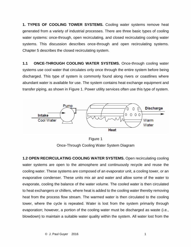
1.1 ONCE-THROUGH COOLING WATER SYSTEMS. Once-through cooling water
systems use cool water that circulates only once through the entire system before being
discharged. This type of system is commonly found along rivers or coastlines where
abundant water is available for use. The system contains heat exchange equipment and
transfer piping, as shown in Figure 1. Power utility services often use this type of system.
Figure 1
Once-Through Cooling Water System Diagram
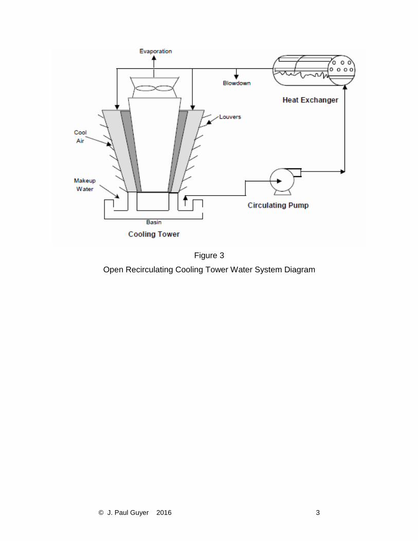
1.2 OPEN RECIRCULATING COOLING WATER SYSTEMS. Open recirculating cooling
water systems are open to the atmosphere and continuously recycle and reuse the
cooling water. These systems are composed of an evaporator unit, a cooling tower, or an
evaporative condenser. These units mix air and water and allow some of the water to
evaporate, cooling the balance of the water volume. The cooled water is then circulated
to heat exchangers or chillers, where heat is added to the cooling water thereby removing
heat from the process flow stream. The warmed water is then circulated to the cooling
tower, where the cycle is repeated. Water is lost from the system primarily through
evaporation; however, a portion of the cooling water must be discharged as waste (i.e.,
blowdown) to maintain a suitable water quality within the system. All water lost from the
Page 5
© J. Paul Guyer 2016 2
system is replaced by makeup water. Recirculating cooling water systems are found in
most air conditioning chiller operations, as well as many heat exchange operations.
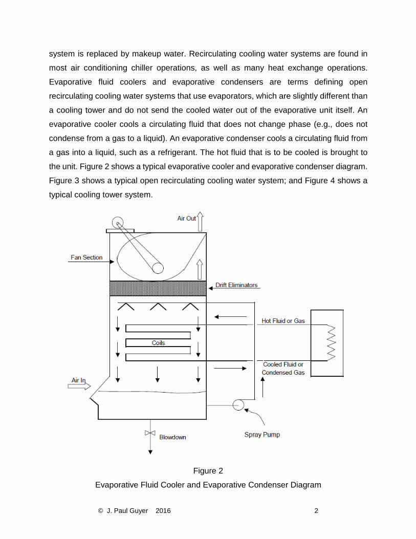
Evaporative fluid coolers and evaporative condensers are terms defining open
recirculating cooling water systems that use evaporators, which are slightly different than
a cooling tower and do not send the cooled water out of the evaporative unit itself. An
evaporative cooler cools a circulating fluid that does not change phase (e.g., does not
condense from a gas to a liquid). An evaporative condenser cools a circulating fluid from
a gas into a liquid, such as a refrigerant. The hot fluid that is to be cooled is brought to
the unit. Figure 2 shows a typical evaporative cooler and evaporative condenser diagram.
Figure 3 shows a typical open recirculating cooling water system; and Figure 4 shows a
typical cooling tower system.
Figure 2
Evaporative Fluid Cooler and Evaporative Condenser Diagram
Page 6
© J. Paul Guyer 2016 3
Figure 3
Open Recirculating Cooling Tower Water System Diagram
Page 7
© J. Paul Guyer 2016 4
Figure 4
Cooling Tower Water System
1.3 TYPES OF COOLING TOWERS. Types of cooling towers include natural draft,
induced draft, and forced draft.
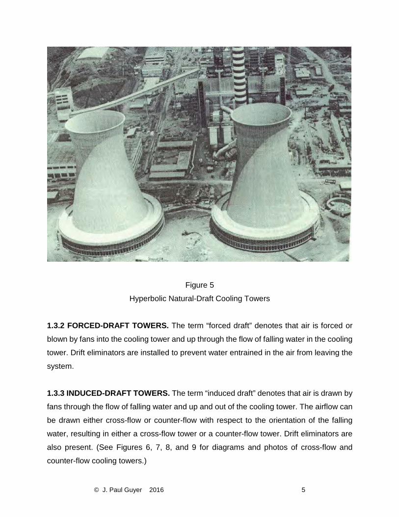
1.3.1 NATURAL-DRAFT TOWERS. In natural-draft towers, airflow through the tower is
achieved naturally (i.e., without any mechanical means such as fans). Air flows across
the falling water and up through the cooling tower as a result of the differential density
between the lighter, heated and humidified, air within the tower and the cooler and dryer
outside air. Fitting the tower with spray nozzles, which create more mixing of air and water
droplets and improve the evaporation efficiency, produces increased water-cooling rates.
Large utility power plants use these large natural-draft cooling towers, which are called
hyperbolic cooling towers due to their hyperbolic shape (see Figure 5).
Page 8
© J. Paul Guyer 2016 5
Figure 5
Hyperbolic Natural-Draft Cooling Towers
1.3.2 FORCED-DRAFT TOWERS. The term “forced draft” denotes that air is forced or
blown by fans into the cooling tower and up through the flow of falling water in the cooling
tower. Drift eliminators are installed to prevent water entrained in the air from leaving the
system.
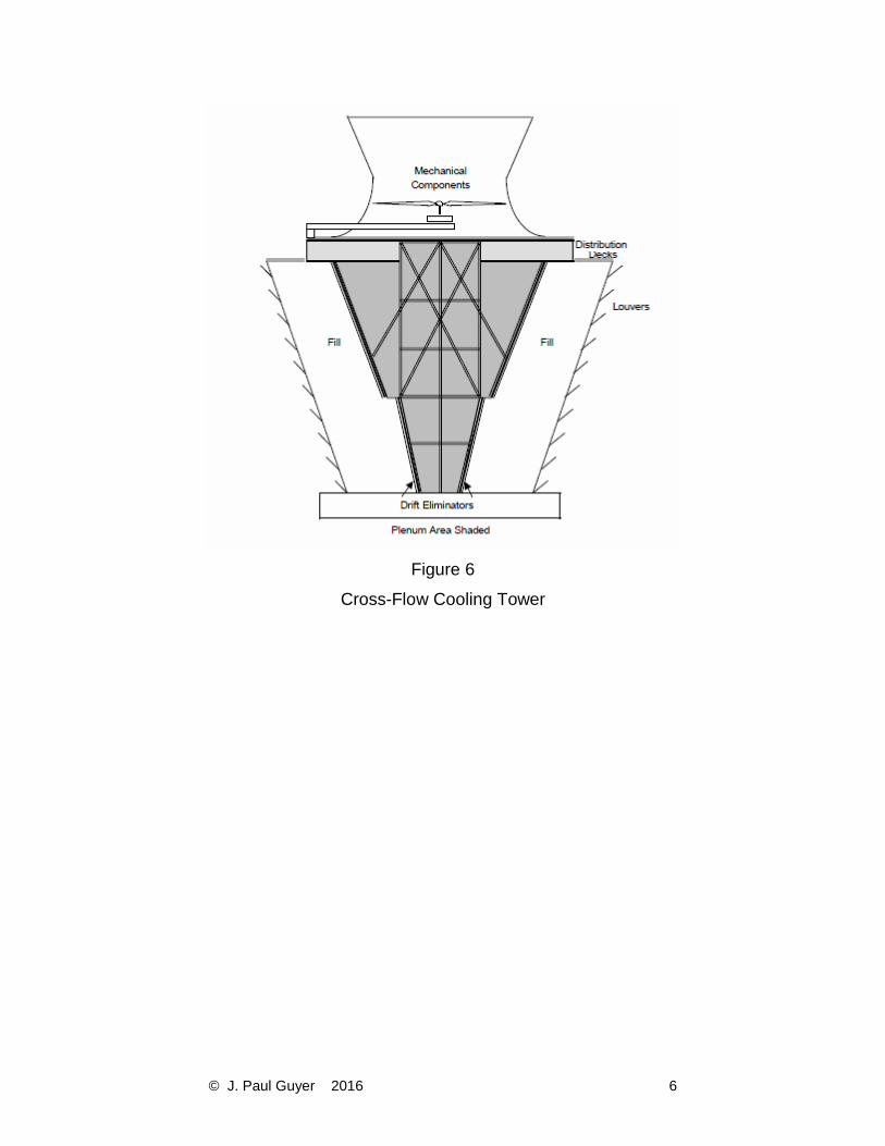
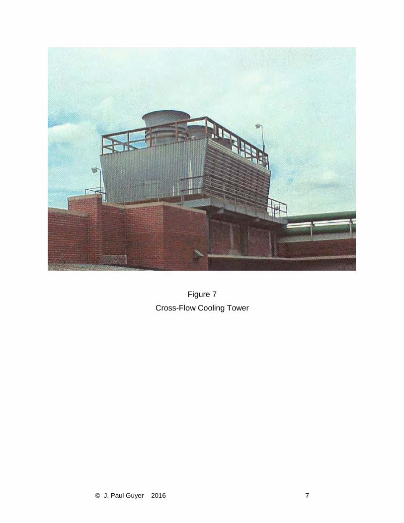
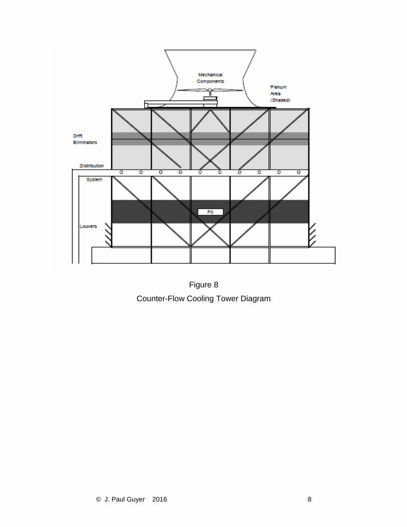
1.3.3 INDUCED-DRAFT TOWERS. The term “induced draft” denotes that air is drawn by
fans through the flow of falling water and up and out of the cooling tower. The airflow can
be drawn either cross-flow or counter-flow with respect to the orientation of the falling
water, resulting in either a cross-flow tower or a counter-flow tower. Drift eliminators are
also present. (See Figures 6, 7, 8, and 9 for diagrams and photos of cross-flow and
counter-flow cooling towers.)
Page 9
© J. Paul Guyer 2016 6
Figure 6
Cross-Flow Cooling Tower
Page 10
© J. Paul Guyer 2016 7
Figure 7
Cross-Flow Cooling Tower
Page 11
© J. Paul Guyer 2016 8
Figure 8
Counter-Flow Cooling Tower Diagram
Page 12
© J. Paul Guyer 2016 9
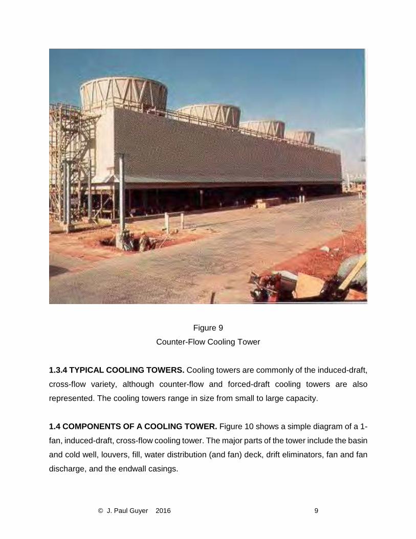
Figure 9
Counter-Flow Cooling Tower
1.3.4 TYPICAL COOLING TOWERS. Cooling towers are commonly of the induced-draft,
cross-flow variety, although counter-flow and forced-draft cooling towers are also
represented. The cooling towers range in size from small to large capacity.
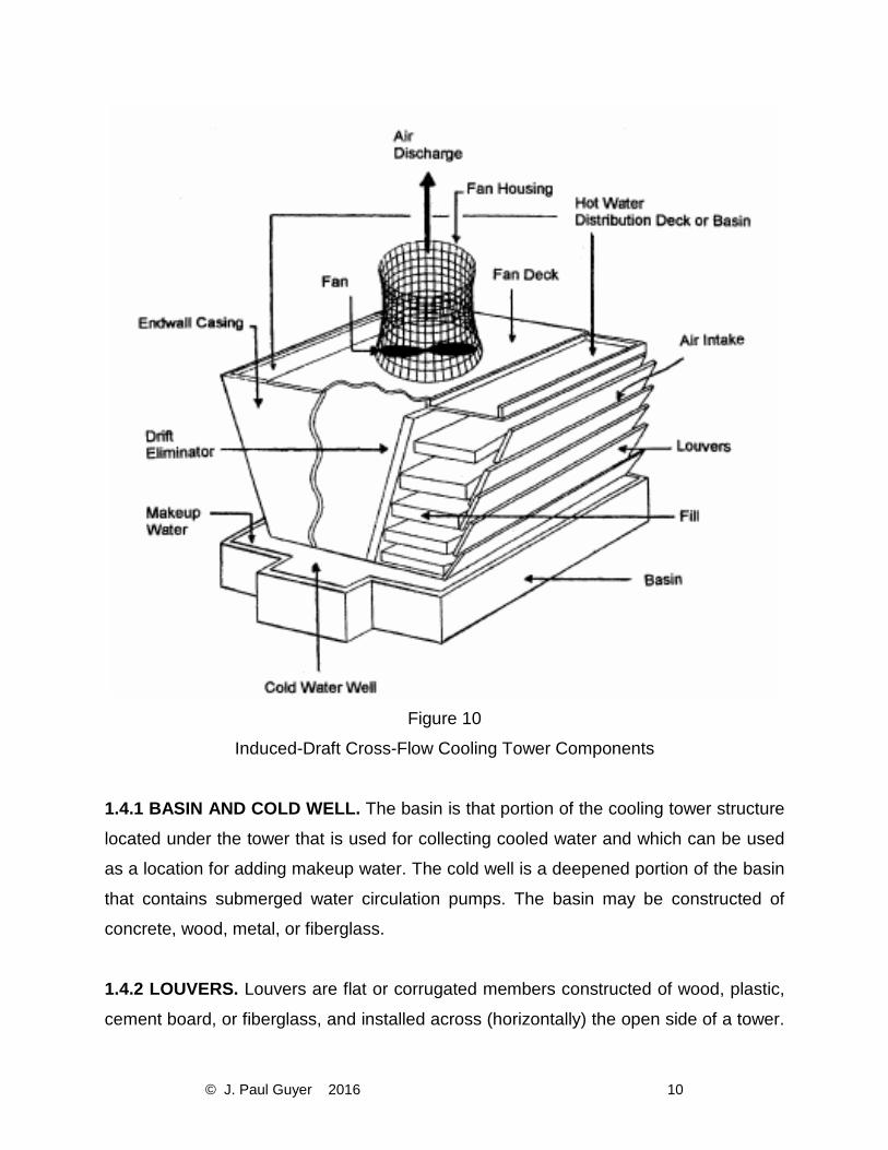
1.4 COMPONENTS OF A COOLING TOWER. Figure 10 shows a simple diagram of a 1-
fan, induced-draft, cross-flow cooling tower. The major parts of the tower include the basin
and cold well, louvers, fill, water distribution (and fan) deck, drift eliminators, fan and fan
discharge, and the endwall casings.
Page 13
© J. Paul Guyer 2016 10
Figure 10
Induced-Draft Cross-Flow Cooling Tower Components
1.4.1 BASIN AND COLD WELL. The basin is that portion of the cooling tower structure
located under the tower that is used for collecting cooled water and which can be used
as a location for adding makeup water. The cold well is a deepened portion of the basin
that contains submerged water circulation pumps. The basin may be constructed of
concrete, wood, metal, or fiberglass.
1.4.2 LOUVERS. Louvers are flat or corrugated members constructed of wood, plastic,
cement board, or fiberglass, and installed across (horizontally) the open side of a tower.
Page 14
© J. Paul Guyer 2016 11
The main function of louvers is to prevent water from splashing out of the cooling tower
through the openings where air enters the tower. Louvers are usually set at an angle to
the direction of airflow.
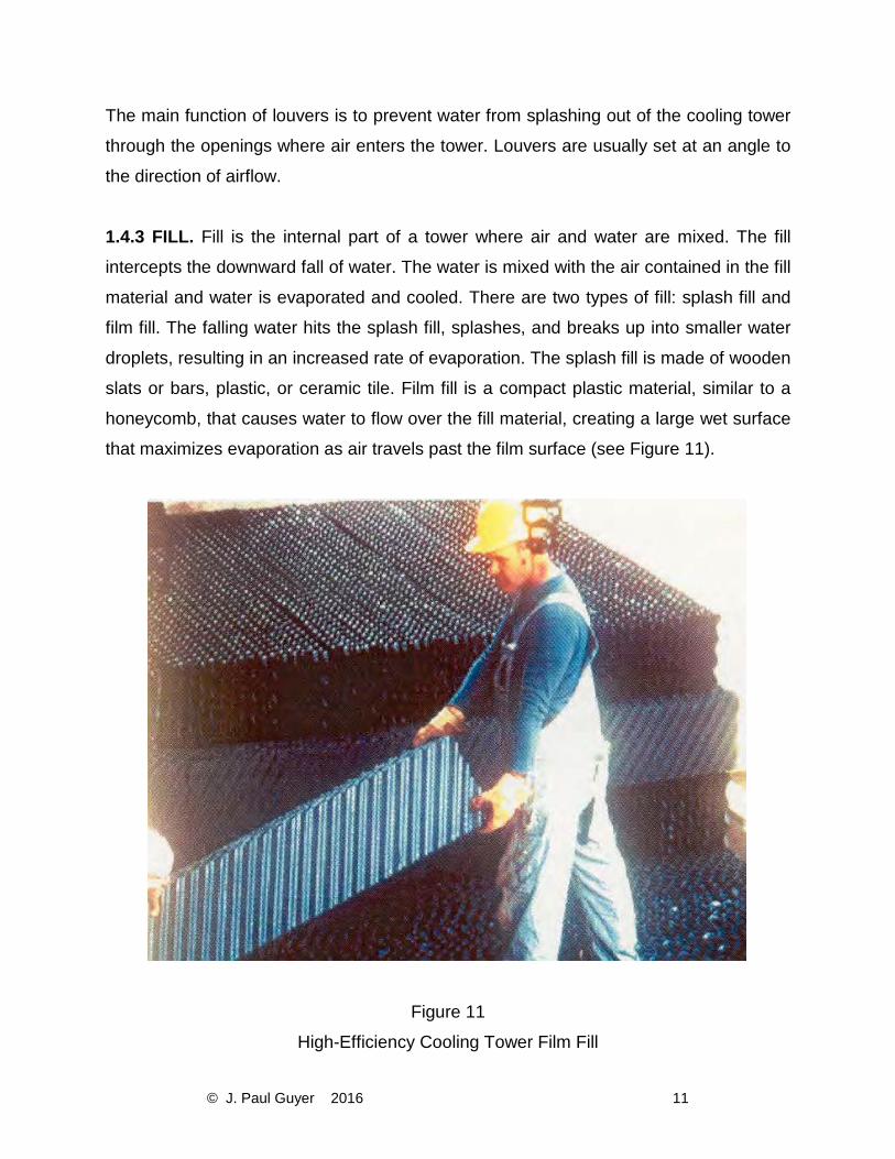
1.4.3 FILL. Fill is the internal part of a tower where air and water are mixed. The fill
intercepts the downward fall of water. The water is mixed with the air contained in the fill
material and water is evaporated and cooled. There are two types of fill: splash fill and
film fill. The falling water hits the splash fill, splashes, and breaks up into smaller water
droplets, resulting in an increased rate of evaporation. The splash fill is made of wooden
slats or bars, plastic, or ceramic tile. Film fill is a compact plastic material, similar to a
honeycomb, that causes water to flow over the fill material, creating a large wet surface
that maximizes evaporation as air travels past the film surface (see Figure 11).
Figure 11
High-Efficiency Cooling Tower Film Fill
Page 15
© J. Paul Guyer 2016 12
1.4.4 DRIFT ELIMINATORS. The drift eliminators efficiently remove water droplets from
the air and return the recovered water to the cooling tower, thereby minimizing the loss
of cooling tower water. They are located in areas that are situated after the fill and water
sprays and just before the area where the air exits the cooling tower (see Figures 6 and
8). Drift eliminators are also known as “mist eliminators.”
1.4.5 WATER DISTRIBUTION AND FAN DECK. In a cross-flow cooling tower, the hot
water basin is used to distribute the warm return water flow uniformly over the tower fill
(see Figure 6). In a counter-flow cooling tower, water sprays are used to distribute the
warm water (see Figure 8). The fan deck supports the motor and fan of the water spray
system. The stack is the structure (typically a cylinder) that encloses the fan and directs
warm, humid discharge air upward and out of the cooling tower.
1.4.6 CELL. This is the smallest subdivision of a large cooling tower in which the fan can
operate as an independent unit. A midwall casing must separate each end of the cell from
the adjacent cells to ensure all air flow induced by the cell fan is drawn only through the
cell fill and mist eliminator air path. Figure 7 illustrates a typical three-cell cross-flow
cooling tower. Figure 9 illustrates a typical four-cell counter-flow cooling tower.
1.5 COMMON COOLING WATER SYSTEM PROBLEMS. Water-related problems can
cause system downtime, loss of equipment efficiency, the need for capital replacement
of equipment, and can increase the risk of disease from pathogenic microorganisms. An
open recirculating cooling tower system has a greater potential for these problems than
does a once-through cooling water system, due to the air- and water-mixing design of the
open recirculating system. These problems are associated with water-caused deposits,
corrosion, or microbiological organisms, and occur for various reasons:
• The cooling tower is essentially a huge air scrubber that can introduce materials
such as microorganisms, gases, dust, and dirt into the circulating water, which
provides an excellent growth environment for pathogenic microorganisms. These
materials can contribute to the formation of deposits and cause corrosion.
Page 16
© J. Paul Guyer 2016 13
• If the water is not properly treated and its quality maintained, corrosion and scale
and solids deposition can occur. The potential for these problems results from the
nature of the cooling system design and the operating conditions, including water
evaporation, mineral concentration, and water temperatures of up to 54 °C (130
°F).
• The constant addition of makeup water results in increased quantities of mineral
constituents that can form scale, deposits, and corrosion. Blowdown control and
proper water treatment can minimize these problems.
• The film fill contains small water and air passages that can become plugged,
thereby causing a reduction in cooling tower operational efficiency due to reduced
water evaporation (see paragraph 4-1.4.3).
• Current designs for heat exchangers and cooling towers provide for more efficient
operation than in the past, but unexpected water problems may occur.
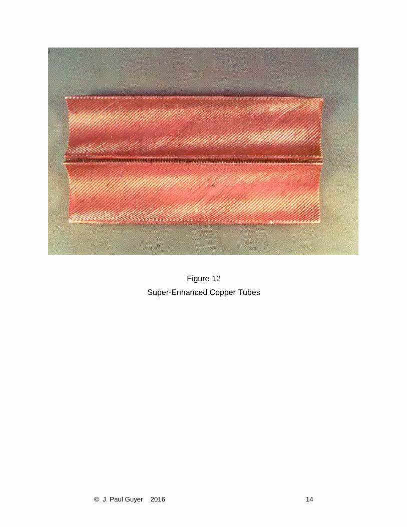
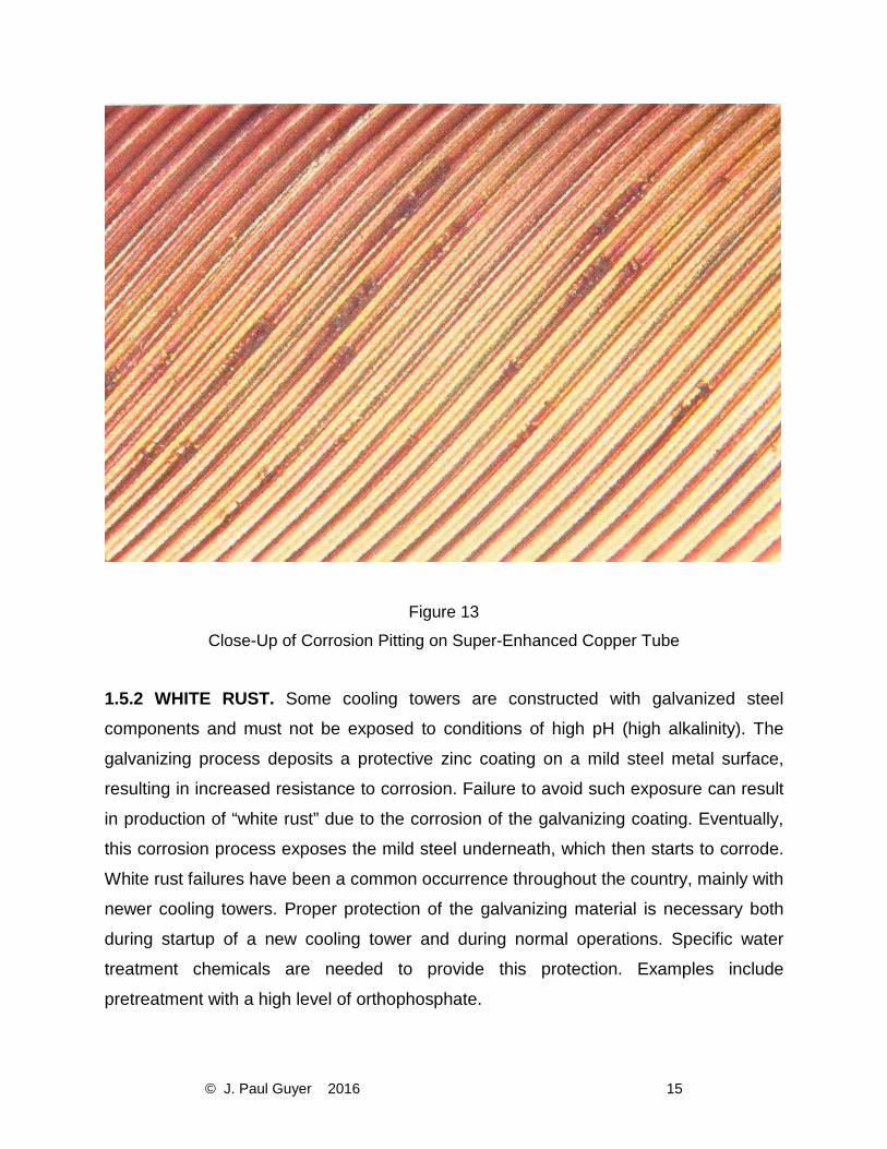
1.5.1 ENHANCED AND SUPER-ENHANCED CHILLER CONDENSER TUBING. Recent
air conditioning chiller equipment designs incorporate enhanced and super-enhanced
chiller condenser tubes. Previous designs have used smooth-bored waterside condenser
tubing. The enhanced tube is machined with rifled grooves that provide an increased
surface area and a resultant increase in heat transfer; however, the rifled grooves and
ridges tend to entrap SS (i.e., dirt, silt, sand, and old corrosion products), which are
deposited from the cooling water as it passes through the tube. This deposition of material
on metal surfaces can create a type of localized corrosion called “under-deposit
corrosion.” This situation has resulted in numerous cases of tube failure. The super-
enhanced chiller tubes have even finer grooves and ridges, making this type of tubing
even more susceptible to under-deposit corrosion. (See Figures 12 and 13, which show
photos of super-enhanced copper tubes.)
Page 17
© J. Paul Guyer 2016 14
Figure 12
Super-Enhanced Copper Tubes
Page 18
© J. Paul Guyer 2016 15
Figure 13
Close-Up of Corrosion Pitting on Super-Enhanced Copper Tube
1.5.2 WHITE RUST. Some cooling towers are constructed with galvanized steel
components and must not be exposed to conditions of high pH (high alkalinity). The
galvanizing process deposits a protective zinc coating on a mild steel metal surface,
resulting in increased resistance to corrosion. Failure to avoid such exposure can result
in production of “white rust” due to the corrosion of the galvanizing coating. Eventually,
this corrosion process exposes the mild steel underneath, which then starts to corrode.
White rust failures have been a common occurrence throughout the country, mainly with
newer cooling towers. Proper protection of the galvanizing material is necessary both
during startup of a new cooling tower and during normal operations. Specific water
treatment chemicals are needed to provide this protection. Examples include
pretreatment with a high level of orthophosphate.
Page 19
© J. Paul Guyer 2016 16
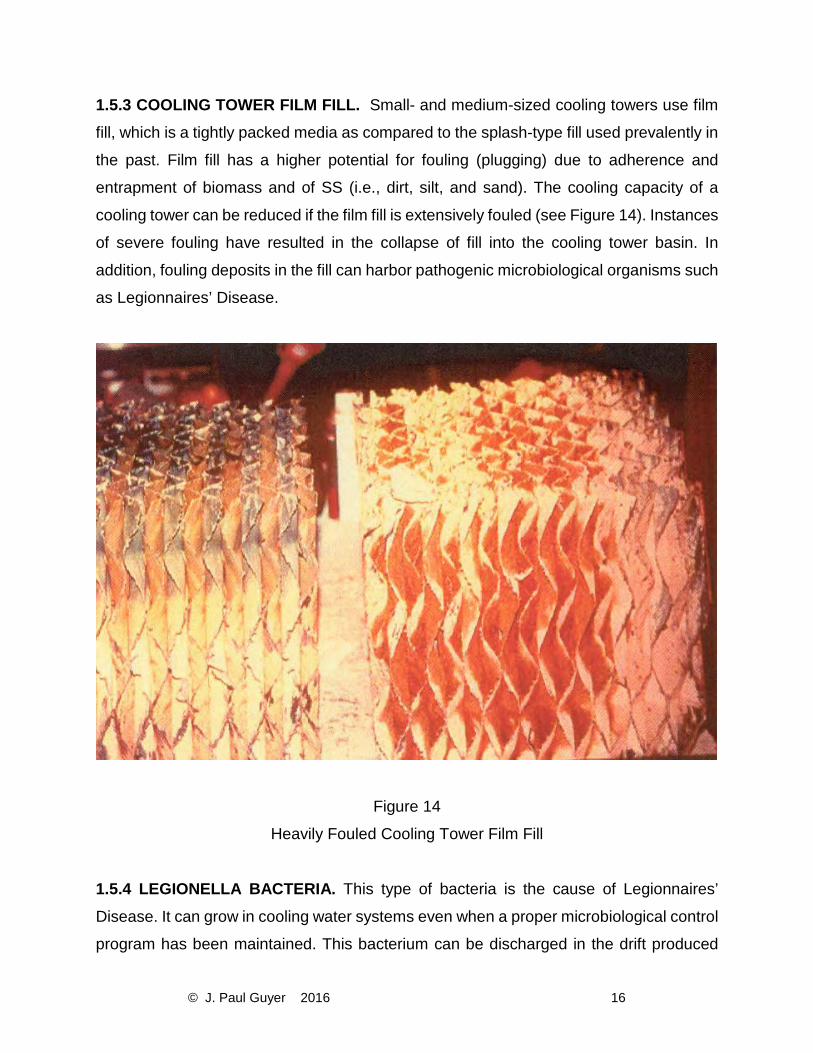
1.5.3 COOLING TOWER FILM FILL. Small- and medium-sized cooling towers use film
fill, which is a tightly packed media as compared to the splash-type fill used prevalently in
the past. Film fill has a higher potential for fouling (plugging) due to adherence and
entrapment of biomass and of SS (i.e., dirt, silt, and sand). The cooling capacity of a
cooling tower can be reduced if the film fill is extensively fouled (see Figure 14). Instances
of severe fouling have resulted in the collapse of fill into the cooling tower basin. In
addition, fouling deposits in the fill can harbor pathogenic microbiological organisms such
as Legionnaires’ Disease.
Figure 14
Heavily Fouled Cooling Tower Film Fill
1.5.4 LEGIONELLA BACTERIA. This type of bacteria is the cause of Legionnaires’
Disease. It can grow in cooling water systems even when a proper microbiological control
program has been maintained. This bacterium can be discharged in the drift produced
Page 20
© J. Paul Guyer 2016 17
from all types of cooling tower systems. If a susceptible person inhales the bacteria, the
disease could possibly develop. Due to increased awareness by cooling tower operators
and the water treatment industry in general, the risk of being infected by Legionella
Pneumophila or other pathogenic microorganism from a cooling tower system is probably
not much greater today than it was a few years ago. Still, a number of outbreaks of
Legionnaires’ Disease are reported each year throughout the country. See paragraph 4-
4.7 for more information on controlling Legionella.
Page 21
© J. Paul Guyer 2016 18
2. COOLING TOWER WATER CALCULATIONS 2.1 PRINCIPLES OF COOLING TOWER SYSTEM OPERATIONS. The function of a
cooling tower is to dissipate heat from water-cooled refrigeration, air-conditioning and
industrial process systems. Water is typically the heat transfer medium used to dissipate
the heat. A cooling tower uses a combination of heat and mass transfer (evaporation) to
cool the water flowing through the tower. Conductive heat transfer accounts for 20 to 30%
of the total heat dissipated. The remaining 70 to 80% of total cooling is the result of
evaporative cooling of about 1 to 2% of the recirculating water, depending on the
decrease in temperature across the tower. It takes approximately 2,326,000 joules to
evaporate 1 kilogram of water (1000 BTU per 1 pound of water). If this amount of heat is
extracted from 454 kilograms (1000 pounds) of water, approximately 0.45 kilogram (1
pound) of water will be evaporated and the temperature will drop 0.55 oC (1 oF). If 4.5
kilograms (10 pounds) of water are evaporated, the water temperature will drop 5.5 oC
(10 oF). The water lost by evaporation is replaced with makeup water. Water is also added
to replace water lost through tower drift (loss of water from the tower as a fine mist), leaks
in the system (unintentional blowdown), and water discharged as intentional blowdown.
Water that is added to the cooling tower to replace all of these losses is known as cooling
tower makeup water.
2.1.1 RELATIONSHIP BETWEEN EVAPORATION, BLOWDOWN, AND MAKEUP. The
operation of cooling towers can be described by the relationship between evaporation,
blowdown, and makeup. Makeup water must equal blowdown water plus water
evaporation to maintain a constant operating water level in the system:
EQUATION | M = B + E (1)
Where
M = makeup water, liters/sec (gpm)
B = blowdown, liters/sec (gpm) (all sources)
E = evaporation, liters/sec (gpm)
Page 22
© J. Paul Guyer 2016 19
NOTE: Blowdown (B) includes discharge to sewer, drift loss, and any leaks from the
systems.
EXAMPLE: M = 6.3 liters/sec (100 gpm)
B = 0.63 liters/sec (100 gpm)
E = 5.67 liters/sec (90 gpm)
2.1.2 CYCLES OF CONCENTRATION (COC). One of the common terms used in
describing the water use efficiency of cooling tower water systems is COC. COC
represents the relationship between the makeup water quantity and blowdown quantity.
COC is a measure of the total amount of minerals that is concentrated in the cooling tower
water relative to the amount of minerals in the makeup water or to the volume of each
type of water. The higher the COC, the greater the water use efficiency. Most cooling
tower systems operate with a COC of 3 to 10, where 3 represents acceptable efficiency
and 10 represents very good efficiency. It has been found that the range of 5 to 7 COC
represents the most cost-effective situation.
2.1.2.1 CALCULATING COC BY VOLUME. If both makeup and blowdown water
volumes are known, COC by volume can be calculated. The term is defined as:
EQUATION | C = M / B (2)
Where
C = COC, no units
M = makeup water, kg/hr (gpm)
B = blowdown losses, kg/hr (gpm)
EXAMPLE: M = 6.3 liters/sec (100 gpm)
B = 0.63 liters/sec (10 gpm)
C = M/B = 10
2.1.2.2 DETERMINING COC BY WATER ANALYSES. To determine COC, you must
know the mineral content of both makeup and blowdown water. For example, you must
Page 23
© J. Paul Guyer 2016 20
determine both the conductivity of the recirculating cooling tower water and the
conductivity of the makeup water. (Note that the blowdown water will have the same
conductivity as the recirculating water.) Conductivity is commonly measured in
micromhos (μmhos). You can also estimate COC by using other water quality parameters
such as chlorides, silica, or sulfates. The relationship is represented by this equation:
EQUATION | C = Bµmhos
Mµmhos or BCI
MCI (3)
Where
C = COC, no units
Bμmhos = conductivity of blowdown (recirculating water), micromhos
(μmhos)
Mμmhos = conductivity of makeup water, μmhos
CI = chlorides in blowdown, ppm
CI = chlorides in makeup water, ppm
EXAMPLE:
The measured conductivity of the blowdown (recirculating water) is 800 micromhos and
the makeup is 300 micromhos.
The COC is:
C = µmhosµmhos
C = 800/300 = 2.67 NOTE: The parameters of conductivity or chloride concentration are used commonly for such measurements. Other water quality parameters can be used, but sometimes with inaccurate results (i.e., calcium, magnesium, alkalinity, and silica can form deposits, meaning they drop out of solution). COC based on these parameters could be considerably less than that based on conductivity or chlorides. Similarly, chemical additions of sulfuric acid can yield higher sulfate levels than those species cycled up naturally.
2.1.2.3 CONTROLLING COC. A simple, sometimes overlooked rule: To increase COC,
decrease blowdown; to decrease COC, increase blowdown.
Page 24
© J. Paul Guyer 2016 21
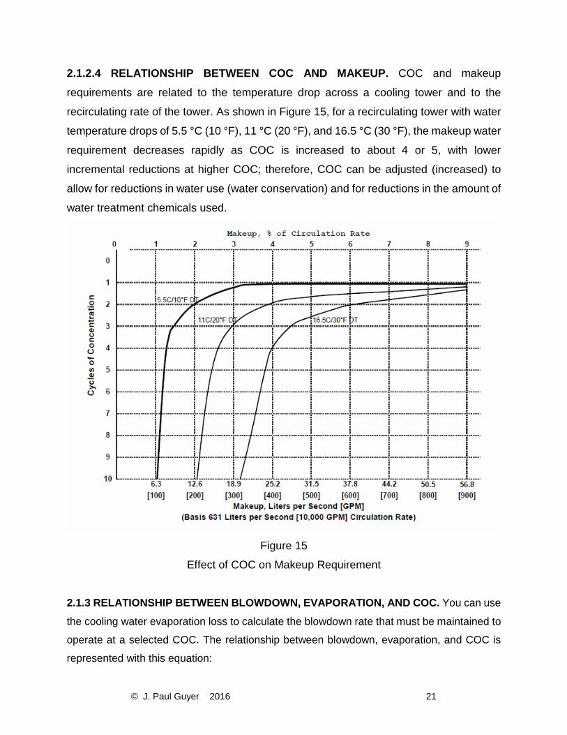
2.1.2.4 RELATIONSHIP BETWEEN COC AND MAKEUP. COC and makeup
requirements are related to the temperature drop across a cooling tower and to the
recirculating rate of the tower. As shown in Figure 15, for a recirculating tower with water
temperature drops of 5.5 °C (10 °F), 11 °C (20 °F), and 16.5 °C (30 °F), the makeup water
requirement decreases rapidly as COC is increased to about 4 or 5, with lower
incremental reductions at higher COC; therefore, COC can be adjusted (increased) to
allow for reductions in water use (water conservation) and for reductions in the amount of
water treatment chemicals used.
Figure 15
Effect of COC on Makeup Requirement
2.1.3 RELATIONSHIP BETWEEN BLOWDOWN, EVAPORATION, AND COC. You can use
the cooling water evaporation loss to calculate the blowdown rate that must be maintained to
operate at a selected COC. The relationship between blowdown, evaporation, and COC is
represented with this equation:
Page 25
© J. Paul Guyer 2016 22
EQUATION | B = E / (C − 1) (4)
Where
B = blowdown liters per day or liters per second (gpd or gpm)
E = evaporation, liters per day or liters per second (gpd or gpm)
C = COC, no units
EXAMPLE:
A cooling tower evaporates 37.8 liters per second (600 gallons per minute) and operates at
4 COC:
EQUATION | B = 37.8 I/sec (600 gpm)/(4 − 1) = 12.6 l/sec (gpm) (5)
a) This formula is derived using data from previously presented equations:
(7) M = B+E from paragraph 2.1.1 (Equation 1)
(8) C = M/B from paragraph 2.1.2.1 (Equation 2)
(9) C = (B+E)/B from Equations (7) and (8) above
(10) C = 1+(E/B) rearranging Equation (9)
(11) (C-1) = E/B rearranging Equation (10)
(12) B = E/(C-1) rearranging Equation (11)
a) If you know the quantity of evaporation, you can calculate the blowdown
required for a given value of COC. You can estimate the evaporation using
simple “rule of thumb” estimates:
b) For a typical recirculating cooling tower water system, approximately 1% of the
recirculating rate (R) of the cooling water is evaporated for every 5.5 °C (10 °F)
temperature drop in the cooling water as it passes through the tower; therefore,
you may calculate the evaporation rate (E) this way:
EQUATION | E(l/sec) = 0.01 ∗ R(l/sec) ∗△ T drop in °C / 5.5 °C (13)
Since 0.01 / 5.5 = 0.0018, this can be condensed to:
EQUATION | E = R ∗△ T ∗ 0.0018 (14)
Or
EQUATION | E = R ∗△ T/550 (15)
NOTE: Newer cooling towers can have 0.75% of the recirculation rate evaporated for
every 5.5 °C (10 °F) drop.
Page 26
© J. Paul Guyer 2016 23
EXAMPLE 4-2:
c) A cooling system operates at 315 liters per second (5000 gallons per minute).
The temperature drop through the tower is 7.8 °C (14 °F). The evaporation
estimate is represented by this equation:
EQUATION | E = 0.01 ∗ 315 l/sec (5000 gpm) ∗ 7.8 °C (14 °F)/5.5 °C(10 °F) =
4.5 l/sec (70 gpm) (16)
Or
EQUATION | E = 315 ∗ 7.8/550 = 4.5 l/sec (70 gpm) (17)
d) For a cooling tower system serving air conditioner and chiller operations, the
evaporation rate used depends on the type of chiller:
7. Approximately 20 liters per hour per kilowatt (1.5 gallons per hour per
ton) for centrifugal, reciprocating, and screw-type chillers.
8. Approximately 40 liters per hour per kilowatt (3 gallons per hour per ton)
for absorption-type chillers.