Page 1
ADVANCES in NATURAL and APPLIED SCIENCES
ISSN: 1995-0772 Published BYAENSI Publication EISSN: 1998-1090 http://www.aensiweb.com/ANAS
2017 March 11(3): pages 182-189 Open Access Journal
ToCite ThisArticle: Velmurugan Ramakrishnan, Mahadevan Krishnan, Professor, Ramesh Ramamoorthy, An Inverter with Interleaved FlyBack Topology Using DCM And MPPT For Photovoltaic System. Advances in Natural and Applied Sciences. 11(3); Pages: 182-189
An Inverter with Interleaved FlyBack Topology Using DCM And MPPT For Photovoltaic System
1Velmurugan Ramakrishnan, 2Mahadevan Krishnan, 3Professor, Ramesh Ramamoorthy, 1Assistant Professor, Department of EEE, Christian College of Engineering &Tech, Oddanchatram, Dindigul, Tamilnadu, India. 2Department of EEE, P.S.N.A college of Engineering & Tech,Dindigul , Tamilnadu, India. 3PG Scholar Department of EEE, Christian College of Engineering and Technology, Oddanchatram, Dindigul, India.
Received 18 January 2017; Accepted 22 March 2017; Available online 28 March 2017
Address For Correspondence: Velmurugan Ramakrishnan, Assistant Professor, Department of EEE, Christian College of Engineering &Tech, Oddanchatram, Dindigul, Tamilnadu, India.
Copyright © 2017 by authors and American-Eurasian Network for ScientificInformation (AENSI Publication). This work is licensed under the Creative Commons Attribution International License (CC BY). http://creativecommons.org/licenses/by/4.0/
ABSTRACT This Paper presents analysis, design, and implementation of an isolated grid-connected inverter for photovoltaic (PV) application based on interleaved flyback converter topology operating in discontinuous current mode (DCM). In today’s PV inverter technology, the simple and the low-cost advantage of the flyback topology is promoted only at very low power as micro inverter. Therefore, the primary objective of this study is to design the flyback converter at high power and demonstrate its practicality with good performance as a central type PV inverter. For this purpose, an inverter system rated at 2KW is developed by interleaving of only three flyback cells with added benefit of reduced size of passive filtering elements. A simulation model is developed in the piecewise linear electrical circuit simulator(PLECS). Then, the design is verified and optimized for the best performance based on the simulation result. Finally, a prototype at rated power is built and evaluated under the realistic conditions. The efficiency of the inverter, the total harmonic distortion(THD) of the grid current, and the power factor are measured as 90.16%, 4.42%, and 0.998%, respectively. Consequently, it is demonstrated that the performance of the proposed system is comparable to the commercial isolated PV inverters in the market, but it may have some cost advantage.
KEYWORDS: Flyback converter, harmonics, interleaved converters, photovoltaic inverters.
INTRODUCTION
The solar energy is considered as one of the most renewable and freely available source of energy and the
candidate to plat a greater role in the energy market of the world in the near future. Therefore, the research and
development in the solar technology field in the rise. However, the high cost of the technology still limits its
usage globally. The Low cost is greatly important for commercialization especially in small electric power
system including the residential applications. Therefore, the primary objective of the study presented in this
paper is to contribute to the research and development in the photovoltaic inverter technology by trying the
flyback topology at high power. If it is implemented effectively with good performance, the developed inverter
system can be a low cost alternative to the commercial isolated grid-connected PV inverter in the market.
The simple structure of the flyback topology and easy power flow control with high power quality at the
grid recognized as the lowest cost converter among the isolated topologies since it uses the least number of
components. This advantage comes from the ability of the flyback topology combining the energy storage
inductor with the transformer. In other type of isolated topologies, the energy storage inductor and the
Page 2
183 Velmurugan Ramakrishnan et al., 2017/Advances in Natural and Applied Sciences. 11(3) March 2017, Pages: 182-189
transformer are separate elements. While the inductor is responsible for energy storage, the transformer on the
other hand is responsible for energy transfer over a galvanic isolation [7]. The combination of these two
components in a flyback topology eliminates the bulky and costly energy storage inductor and therefore leads to
a reduction in cost and size of the converter. However, we have to make it clear here that the cost depends on
the implementation as much as the selected topology, so not every implementation of the flyback topology leads
to a low-cost converter. For this reason, as we try to achieve the high-power implementation of the flyback
converter with good performance, which is our primary research contribution, we will also try to preserve the
cost advantage during the final implementation step.
Practical implementation of a transformer with relatively large energy storage capability is always a
challenge. The air gap is where the energy is stored, so a high-power flyback converter design needs a relatively
large air gap. As a result of this, the magnetizing inductance is going to be quite small. The aforementioned
challenge is actually achieving such as a small magnetizing inductance with low leakage inductance. A flyback
converter built with a transformer that has large leakage flux and poor coupling will have poor energy transfer
efficiency. Mainly for this reason, the flyback converters are generally not designed for high power. As a result,
the flyback topology finds a limited role in photovoltaic applications only at very low power as a microinverter
[10]-[13]. In this technology, every PV panel comes with a dedicated energy conversion unit; a microinverter
attached to the output terminals. For this reason, the technology is also named as AC PV module application
[14]-[18]. In this practice, many such AC PV modules are connected in parallel to get the desired power output.
The maximum harvesting of solar energy in this method is the best since there is a dedicated maximum power
point tracker (MPPT) for each PV panel [19]. However, the overall cost of this application is higher compared
to the central type inverter systems.
Nevertheless, when advanced design methods are employed effectively, single-stage flyback converters can
be designed and used in high power applications as well. Furthermore, the interleaving of these high-power
flyback stages (cells) facilitates developing a central type PV inverter. The added benefit of interleaving is that
the frequency of the ripple components (undesired harmonics) at the waveforms are increased in proportion to
the number of interleaved cells. This feature facilitates easy filtering of the ripple components or using smaller
sized filtering elements. The ability to reduce the size of passive elements is beneficial for reducing the cost and
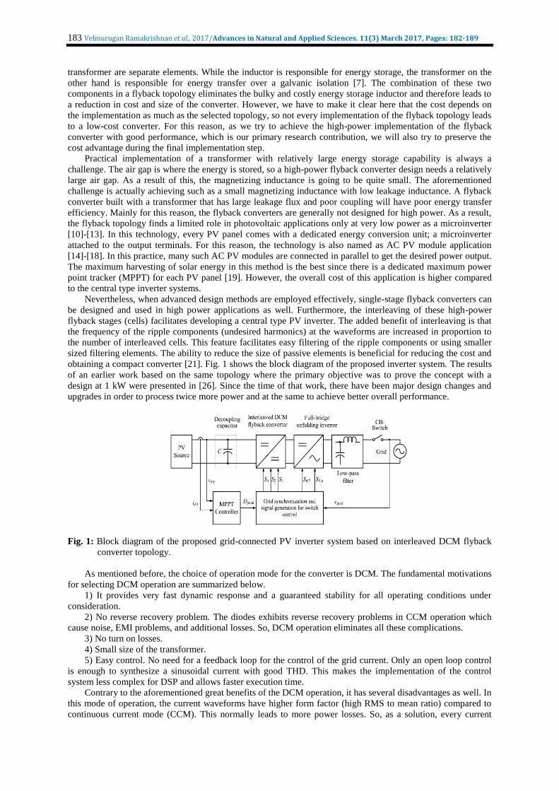
obtaining a compact converter [21]. Fig. 1 shows the block diagram of the proposed inverter system. The results
of an earlier work based on the same topology where the primary objective was to prove the concept with a
design at 1 kW were presented in [26]. Since the time of that work, there have been major design changes and
upgrades in order to process twice more power and at the same to achieve better overall performance.
Fig. 1: Block diagram of the proposed grid-connected PV inverter system based on interleaved DCM flyback
converter topology.
As mentioned before, the choice of operation mode for the converter is DCM. The fundamental motivations
for selecting DCM operation are summarized below.
1) It provides very fast dynamic response and a guaranteed stability for all operating conditions under
consideration.
2) No reverse recovery problem. The diodes exhibits reverse recovery problems in CCM operation which
cause noise, EMI problems, and additional losses. So, DCM operation eliminates all these complications.
3) No turn on losses.
4) Small size of the transformer.
5) Easy control. No need for a feedback loop for the control of the grid current. Only an open loop control
is enough to synthesize a sinusoidal current with good THD. This makes the implementation of the control
system less complex for DSP and allows faster execution time.
Contrary to the aforementioned great benefits of the DCM operation, it has several disadvantages as well. In
this mode of operation, the current waveforms have higher form factor (high RMS to mean ratio) compared to
continuous current mode (CCM). This normally leads to more power losses. So, as a solution, every current
Page 3
184 Velmurugan Ramakrishnan et al., 2017/Advances in Natural and Applied Sciences. 11(3) March 2017, Pages: 182-189
carrying path including the switching devices should have low resistivity. Another drawback of DCM operation
is the current pulses with large peaks and high amount of discontinuity in the waveforms. Device paralleling is a
way to handle the high peak currents. Nevertheless, these disadvantages can be considerably reduced by
interleaving of several cells. As a first benefit, the current in each cell will have much less peak but the same
amount of discontinuity. However, the discontinuity will be significantly reduced as soon as the cells connect at
the common point. All this benefits come from the ability of phase-shifted several cells spreading the power
flow evenly over the switching cycle with minimum discontinuity at the source and grid side. In brief, the
effective interleaving has the potential to solve or greatly reduce the adverse effects of the DCM operation [21].
Consequently, the circuit diagram of the proposed inverter system based on three-cell interleaved DCM flyback
converter topology is shown in Fig. 2
Fig. 2: Circuit schematic of the proposed PV inverter system based on three-cell interleaved flyback converter
topology
In conclusion, this study has developed and presented the technology in full detail to produce a grid-tied,
isolated, and central type inverter based on the flyback converter topology at 2 kW, which is not available in
today’s PV market. The developed system has performed satisfactorily according to major specifications such as
the efficiency and the THD of the grid current. Moreover, the study has developed high-power flyback
transformers at 700 W and below with extremely low leakage inductance. We also consider this outcome as the
significant research contribution since this technology may lead to the development of different applications
where the low-cost and simplicity are always an issue.
The remainder of the paper is organized as follows. Section II describes the converter topology and defines
the operating principles. Section III performs the analysis of the converter and derives the design equations.
Section IV presents the design of the converter in steps. Section V and VI give the simulation and the
experimental results, respectively. Finally, Section VII provides the conclusions.
Converter Description And Operating Principles:
As shown in Fig. 2, the PV source is applied to a three-cell interleaved flyback converter through a
decoupling capacitor. Each flyback converter uses a metal–oxide–semiconductor field-effect transistor
(MOSFET) for switching at the primary side, a flyback transformer, and a diode at the secondary side. The
topology also has to employ a full-bridge inverter and a low-pass filter for proper interface to the grid. When the
flyback switches (S1, S2, S3) are turned on, a current flows from the common point (the PV source) into the
magnetizing inductance of the flyback transformers, and energy is stored in the form of magnetic field. During
the on time of the switches, no current flows to the output due to the position of the secondary side diodes;
therefore, energy to the grid is supplied by the capacitor and the inductor. When the flyback switches are turned
off, the energy stored in the magnetizing inductances is transferred into the grid in the form of current. So, the
flyback inverter acts like a voltage-controlled current source.
The converter is operated in DCM for easy and stable generation of AC currents at the grid interface. The
DCM operation of converter under open-loop control produces triangular current pulses at every switching
period. If sinusoidal PWM method is used for control, the inverter will regulate these current pulses into a
sinusoidal current in phase with the grid voltage [22]. Such currents are shown in Figs. 3 and 4 for a conceptual
case. Specifically, Fig. 3 shows the conceptual flyback converter input currents and Fig. 4 shows the output
currents. As it is seen, the instantaneous currents are composed of discontinuous current pulses with peaks that
fall within a sinusoidal envelope since their pulse widths are sinusoidally modulated.
Page 4
185 Velmurugan Ramakrishnan et al., 2017/Advances in Natural and Applied Sciences. 11(3) March 2017, Pages: 182-189
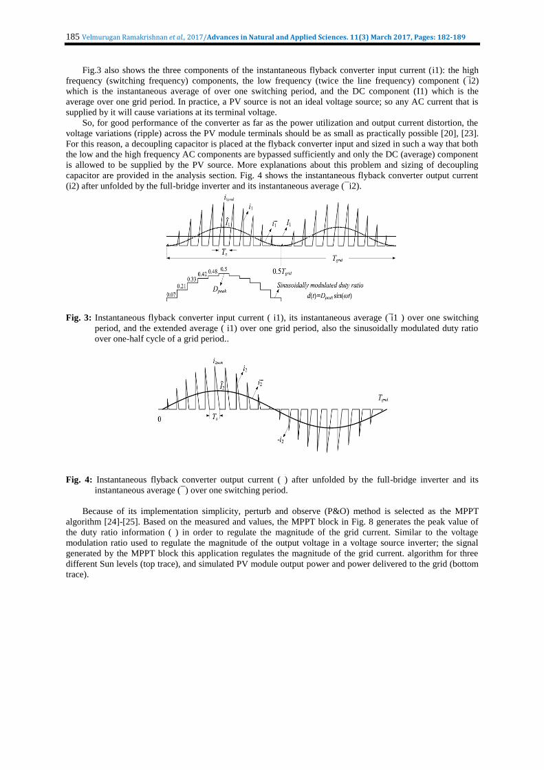
Fig.3 also shows the three components of the instantaneous flyback converter input current (i1): the high
frequency (switching frequency) components, the low frequency (twice the line frequency) component ( ̅i2)
which is the instantaneous average of over one switching period, and the DC component (I1) which is the
average over one grid period. In practice, a PV source is not an ideal voltage source; so any AC current that is
supplied by it will cause variations at its terminal voltage.
So, for good performance of the converter as far as the power utilization and output current distortion, the
voltage variations (ripple) across the PV module terminals should be as small as practically possible [20], [23].
For this reason, a decoupling capacitor is placed at the flyback converter input and sized in such a way that both
the low and the high frequency AC components are bypassed sufficiently and only the DC (average) component
is allowed to be supplied by the PV source. More explanations about this problem and sizing of decoupling
capacitor are provided in the analysis section. Fig. 4 shows the instantaneous flyback converter output current
(i2) after unfolded by the full-bridge inverter and its instantaneous average ( ̅ i2).
Fig. 3: Instantaneous flyback converter input current ( i1), its instantaneous average ( ̅i1 ) over one switching
period, and the extended average ( i1) over one grid period, also the sinusoidally modulated duty ratio
over one-half cycle of a grid period..
Fig. 4: Instantaneous flyback converter output current ( ) after unfolded by the full-bridge inverter and its
instantaneous average ( ̅ ) over one switching period.
Because of its implementation simplicity, perturb and observe (P&O) method is selected as the MPPT
algorithm [24]-[25]. Based on the measured and values, the MPPT block in Fig. 8 generates the peak value of
the duty ratio information ( ) in order to regulate the magnitude of the grid current. Similar to the voltage
modulation ratio used to regulate the magnitude of the output voltage in a voltage source inverter; the signal
generated by the MPPT block this application regulates the magnitude of the grid current. algorithm for three
different Sun levels (top trace), and simulated PV module output power and power delivered to the grid (bottom
trace).
Page 5
186 Velmurugan Ramakrishnan et al., 2017/Advances in Natural and Applied Sciences. 11(3) March 2017, Pages: 182-189
Simulation diagram:
Fig. 4: PLECS model of the proposed PV inverter system including the power stage and the controller
Fig. 5: Inner block diagramt
Fig. 6: Implemented PLL structure based on the T/4 transport delay echnique
Page 6
187 Velmurugan Ramakrishnan et al., 2017/Advances in Natural and Applied Sciences. 11(3) March 2017, Pages: 182-189
Simulation results:
Fig. 7: Peak value of duty ratio generated by the P&O MPPT
Fig. 8: Simulated waveforms of the grid voltage and current.
Fig. 9: Simulated waveforms of the PV module terminal voltage and the grid current.
Conclusion:
A central type photovoltaic inverter for small electric power system applications rated at 2 kW is
implemented based on the interleaved flyback converter topology. The 2 kW power level is achieved by
interleaving of three flyback cells each rated at 700 W. The flyback topology is selected because of its simple
structure and easy power flow control with high power quality outputs at the grid interface. The experimental
results prove the successful operation of the inverter and compliance to the specifications. The energy
harvesting efficiency of the MPPT controller and the inverter static efficiency are measured as 98.5% and
90.16%, respectively. Also, the THD of the grid current is measured as 4.42% and the power factor is 0.998,
which are confirming the high power quality interface to the grid. Consequently, it is demonstrated that
interleaved flyback topology is practical at high power as a central type PV inverter, which is the main
contribution of this study. Furthermore, the performance of the proposed system is comparable to the
Page 7
188 Velmurugan Ramakrishnan et al., 2017/Advances in Natural and Applied Sciences. 11(3) March 2017, Pages: 182-189
commercial isolated grid-connected PV inverters in the market, but it may have some cost advantage due to its
topological benefit.
REFERENCES
1. “Solar energy,” 2013. Available: http://www.conserve-energy-future.com/SolarEnergy.php.
2. “Global market outlook for photovoltaics 2013-2017,” Europe photovoltaic industry association (EPIA),
(2013, July 23). Available: http://www.epia.org/news/publications.
3. Xue, Y., L. Chang, S.B. Kjaer, J. Bordonau and T. Shimizu, 2004. “Topologies of single-phase inverters for
small distributed power generators: An overview,” IEEE Trans. Power Electron., 19(5): 1305-1314.
4. Kjaer, S.B., J.K. Pedersen and F. Blaabjerg, 2005. “A review of single-phase grid-connected inverters for
photovoltaic modules,” IEEE Trans. Ind. Appl., 41(5): 1292-1306.
5. Li, Y. and Oruganti, 2012. “A low cost flyback CCM inverter for AC module application,” IEEE Trans.
Power Electron., 27(3): 1295-1303.
6. Kasa, N., T. Iida and L. Chen, 2005. “Flyback inverter controlled by sensorless current MPPT for
photovoltaic power system,” IEEE Trans. Ind. Elec., 52(4): 1145-1152.
7. Mohan, N., T.M. Undelandand W.P. Robbins, 2002. Power Electronics: Converters, Applications, and
Design, John Wiley.
8. Olalla, C., D. Clement, M. Rodriguez and D. Maksimovic, 2013. “Architectures and control of submodule
integrated DC–DC converters for photovoltaic applications,” IEEE Trans. Ind. Appl., 28(6): 2980-2997.
9. Tan, G.H., J.Z. Wang and Y.C. Ji, 2007. “Soft-switching flyback inverter with enhanced power decoupling
for photovoltaic applications,” Electric Power Applications, 1(2): 264-274.
10. Zhang, Z., X.-F. He and Y.-F. Liu, 2013. “An optimal control method for photovoltaic grid-tied-interleaved
flyback microinverters to achieve high efficiency in wide load range,” IEEE Trans. Ind. Appl., 28(11):
5074-5087.
11. Hu, H., S. Harb, X. Fang, D. Zhang, Q. Zhang, Z.J. Shen and I. Batarseh, 2012. “A three-port flyback for
PV microinverter applications with power pulsation decoupling capability,” IEEE Trans. Power Electron.,
27(9): 3953-3964.
12. Hu, H., S. Harb, N.H. Kutkut, Z.J. Shen and I. Batarseh, 2013. “A single-stage microinverter without using
electrolytic capacitors,” IEEE Trans. Power Electron., 28(6): 2667-2687.
13. Chen, Y.M. and C.Y. Liao, 2011. “Three-port flyback-type single-phase micro-inverter with active power
decoupling circuit,” in IEEE Energy Conversion Congress and Exposition (ECCE), pp: 501-506.
14. 2001. IEEE Trans. Power Electron., 16(2): 256-263.
15. Gao, M., M. Chen, Q. Mo, Z. Qian, and Y. Luo, 2011. “ esearch on output current of interleaved-flyback in
boundary conduction mode for photovoltaic AC module application,” in IEEE Energy Conversion
Congress and Exposition (ECCE), pp: 770-775.
16. Nanakos, A.C., E.C. Tatakis and N.P. Papanikolaou, 2012. “A weighted-efficiency-oriented design
methodology of flyback inverter for AC photovoltaic modules,” IEEE Trans. Power Electron., 27(7): 3221-
3233.
17. Kim, Y.-H., Y.-H. Ji, J.-G. Kim, Y.-C. Jung and C.-Y. Won, 2013. “A new control strategy for improving
weighted efficiency in photovoltaic AC module-type interleaved flyback inverters,” IEEE Trans. Power
Electron., 28(6): 2688-2699.
18. Shimizu, T., K. Wada and N. Nakamura, 2006. "Flyback-type single-phase utility interactive inverter with
power pulsation decoupling on the DC input for an AC photovoltaic module system," IEEE Trans. Power
Electron., 21(5): 1264-1272.
19. Kim, Y.-H., J.-G. Kim, Y.-H. Ji, C.-Y. Won, and T.-W. Lee, 2010. “Flyback inverter using voltage
sensorless MPPT for AC module systems,” International Power Electronics Conference (IPEC), pp: 948-
953.
20. Liang, Z., R. Guo, J. Li and A.Q. Huang, 2011. “A high-efficiency PV module integrated DC/DC converter
for PV energy harvest in FREEDM systems,” IEEE Trans. Power Electron., 26(3): 897-909.
21. Zengin, S., F. Deveci, M. Boztepe, 2013. “Decoupling capacitor selection in DCM flyback PV
microinverters considering harmonic distortion," IEEE Trans. Power Electron., 28(2): 816-825.
22. Tamyurek, B. and D.A. Torrey, 2011. “A three-phase unity power factor single-stage AC–DC converter
based on an interleaved flyback topology,” IEEE Trans. Power Electron., 26(1): 308-318.
23. Kyritsis, A.C., E.C. Tatakis and N.P. Papanikolaou, 2008. “Optimum design of the current-source flyback
inverter for decentralized grid-connected photovoltaic systems,” IEEE Trans. Energy Convers., 23(1): 281-
293.
24. Benavides, N.D. and P.L. Chapman, 2008. “Modeling the effect of voltage ripple on the power output of
photovoltaic modules,” IEEE Trans. Ind. Electron., 55(7): 2638-2643.
Page 8
189 Velmurugan Ramakrishnan et al., 2017/Advances in Natural and Applied Sciences. 11(3) March 2017, Pages: 182-189
25. Esram, T. and P.L. Chapman, 2007. “Comparison of photovoltaic array maximum power point tracking
techniques,” IEEE Trans. Energy Convers., 22(2): 439-449.
26. Housheng, Z., 2010. “ esearch on MPPT for solar cells based on flyback converter,” in International
Conference on Intelligent Computation Technology and Automation (ICICTA), pp: 36-39.
27. Tamyurek, B. and B. Kirimer, 2013. “An interleaved flyback inverter for residential photovoltaic
applications,” in 15th European Conference on Power Electronics and Applications (EPE), pp: 1-10.
28. Kang, S.H., D. Maksimović, I. Cohen, 2012. “Efficiency optimization in digitally controlled flyback DC–
DC converters over wide ranges of operating conditions,” IEEE Transactions on Power Electronics, 27(8):
3734-3748.
29. Teodorescu, M. Liserre, P. odríguez, 2011. “Grid synchronization in single-phase power converters,” in
Grid Converters for Photovoltaic and Wind Power Systems, Chichester, UK: John Wiley, pp: 63-64.