Heat Transfer Engineering, 28(2):163–172, 2007 Copyright C Taylor and Francis Group, LLC ISSN: 0145-7632 print / 1521-0537 online DOI: 10.1080/01457630601023666 An Investigation of a Falling Film Desiccant Dehumidification/ Regeneration Cooling System SCOTT FEYKA Remec Defense and Space, San Diego, California, USA KAMBIZ VAFAI Department of Mechanical Engineering, University of California at Riverside, Riverside, California, USA The present work outlines a liquid desiccant refrigeration cycle with a significantly higher efficiency, as compared to a traditional chiller cycle operating between the same two thermal reservoirs. The present investigation includes a general cooling design under nominal values. A parametric study enables the determination of the overall cooling and humidity levels as compared to the ambient conditions. Typical cooling achieved by this analysis is approximately 17 ◦ C below the ambient temperature, and the relative humidity of the inlet air can be reduced up to 22 percent. The proposed cycle yields a 18–23 percent higher coefficient of performance as compared to a chiller cycle operating between the same temperatures. The proposed dehumidifier displays close agreement when compared to a standard cross-flow heat exchanger and the general trends and performance of this cycle compare well with previous studies on falling film dehumidifiers. INTRODUCTION Desiccant dehumidification has been studied extensively dur- ing the past several years as a way to dramatically reduce energy consumption of a vapor compression cooling cycle. In this type of system, the water vapor is removed from the air as it is routed to the evaporator in an effort to reduce the cooling load on the air conditioning system. This modified air conditioning cycle, known as a hybrid cooling system, has been shown to help in- crease the coefficient of performance (COP) of the cycle while reducing evaporator and condenser sizes. Analysis of a hybrid system [1] has revealed that the compressor power consumption can be reduced by 25% with an evaporation and condensation area reduction of 34% as compared to a standard vapor com- pression cycle. Two types of liquid desiccant structures have been studied. The first involves a packed bed design first proposed by Lof [2] in 1955 using a triethylene glycol solution as the desiccant. This design incorporates a porous packing material, sprinklers, and a solution pump. The concentrated liquid desiccant is sprayed over the packing material, which forms a thin film along the bed. Address correspondence to Prof. Kambiz Vafai, Department of Mechanical Engineering, University of California at Riverside, A363 Bourns Hall, Riverside, California, 92521-0425 USA. E-mail: [email protected]Similar to a cooling tower design, the inlet air is forced through the packed bed structure in a counter-flow direction, where the weight of the desiccant enables collection at the bottom of the bed. The packed bed structure has been extensively studied by Factor and Grossman [3] with exit condition predictions using a one-dimensional model. Their analysis included a set of differ- ential equations derived from energy and mass balances along a differential slice of the packed column. A finite difference scheme was used to solve these sets of differential equations, revealing the temperature and humidity profiles along the bed. Along the same lines, Radhwan et al. [4] solved a set of four first-order differential equations based on energy and mass bal- ances along a differential slice. They observed that performance enhancements occur by an increase in height and transfer area of the packed bed. Falling film dehumidification was developed in response to the relatively large pressure drops and occasional inconsistent mixing of a packed bed structure. In addition, the falling desic- cant film helps to purify and filter the conditioned air from large organic molecules and prevents the growth of mold, mildew, bacteria, and other airborne microorganisms [5]. The present work is based on a numerical and experimen- tal study of a cross-flow fin tube falling film desiccant dehu- midifier designed and analyzed by Park et al. [6]. The results of this two-dimensional model under isothermal channel flow 163
An Investigation of a FallingFilm Desiccant Dehumidification/Regeneration Cooling System
SCOTT FEYKA
Remec Defense and Space, San Diego, California, USA
KAMBIZ VAFAI
Department of Mechanical Engineering, University of California at Riverside, Riverside, California, USA
The present work outlines a liquid desiccant refrigeration cycle with a significantly higher efficiency, as compared to atraditional chiller cycle operating between the same two thermal reservoirs. The present investigation includes a generalcooling design under nominal values. A parametric study enables the determination of the overall cooling and humiditylevels as compared to the ambient conditions. Typical cooling achieved by this analysis is approximately 17◦C below theambient temperature, and the relative humidity of the inlet air can be reduced up to 22 percent. The proposed cycle yields a18–23 percent higher coefficient of performance as compared to a chiller cycle operating between the same temperatures.The proposed dehumidifier displays close agreement when compared to a standard cross-flow heat exchanger and the generaltrends and performance of this cycle compare well with previous studies on falling film dehumidifiers.
INTRODUCTION
Desiccant dehumidification has been studied extensively dur-ing the past several years as a way to dramatically reduce energyconsumption of a vapor compression cooling cycle. In this typeof system, the water vapor is removed from the air as it is routedto the evaporator in an effort to reduce the cooling load on theair conditioning system. This modified air conditioning cycle,known as a hybrid cooling system, has been shown to help in-crease the coefficient of performance (COP) of the cycle whilereducing evaporator and condenser sizes. Analysis of a hybridsystem [1] has revealed that the compressor power consumptioncan be reduced by 25% with an evaporation and condensationarea reduction of 34% as compared to a standard vapor com-pression cycle.
Two types of liquid desiccant structures have been studied.The first involves a packed bed design first proposed by Lof [2]in 1955 using a triethylene glycol solution as the desiccant. Thisdesign incorporates a porous packing material, sprinklers, anda solution pump. The concentrated liquid desiccant is sprayedover the packing material, which forms a thin film along the bed.
Address correspondence to Prof. Kambiz Vafai, Department of MechanicalEngineering, University of California at Riverside, A363 Bourns Hall, Riverside,California, 92521-0425 USA. E-mail: [email protected]
Similar to a cooling tower design, the inlet air is forced throughthe packed bed structure in a counter-flow direction, where theweight of the desiccant enables collection at the bottom of thebed. The packed bed structure has been extensively studied byFactor and Grossman [3] with exit condition predictions using aone-dimensional model. Their analysis included a set of differ-ential equations derived from energy and mass balances alonga differential slice of the packed column. A finite differencescheme was used to solve these sets of differential equations,revealing the temperature and humidity profiles along the bed.
Along the same lines, Radhwan et al. [4] solved a set of fourfirst-order differential equations based on energy and mass bal-ances along a differential slice. They observed that performanceenhancements occur by an increase in height and transfer areaof the packed bed.
Falling film dehumidification was developed in response tothe relatively large pressure drops and occasional inconsistentmixing of a packed bed structure. In addition, the falling desic-cant film helps to purify and filter the conditioned air from largeorganic molecules and prevents the growth of mold, mildew,bacteria, and other airborne microorganisms [5].
The present work is based on a numerical and experimen-tal study of a cross-flow fin tube falling film desiccant dehu-midifier designed and analyzed by Park et al. [6]. The resultsof this two-dimensional model under isothermal channel flow
163
164 S. FEYKA AND K. VAFAI
Figure 1 Proposed desiccant cooling cycle under nominal operating conditions.
indicate enhanced performance under lower airflow using tri-ethylene glycol as the desiccant. This effect was primarily dueto increased contact time between the air and desiccant. Themodel was validated from experimental data for a cross-flowdehumidifier using both triethylene glycol and lithium bromideas the desiccant.
A comprehensive and detailed simulation of a cross-flow de-humidifier by Ali et al. [7] confirmed Park’s results with ad-ditional performance recommendations. Ali et al.’s [7] studydemonstrated that further dehumidification and cooling couldbe achieved by increasing the height and length of the chan-nel while decreasing the channel width. In addition, they alsodemonstrated marginal heat and mass transfer enhancements bythe addition of conductive ultra fine particles within the liquiddesiccant [8].
Ali and Vafai [9] established the optimal airflow directionand plate inclination effects on a falling film dehumidifier, andfound that optimal cooling and absorption occur under parallelflow configurations. In addition, they demonstrated the occur-rence of heat and mass transfer enhancements under an inclinedconfiguration due to the heightened flow velocities through thechannel. The falling film model was modified and studied by Ra-hamah et al. [10] to incorporate fin temperature variations using
an annular fin approximation under a parallel flow configuration.This parametric study provided correlations along with generaldevice performance and limitations using a calcium chloridedesiccant solution.
ANALYSIS
The proposed cycle is shown in Figure 1 under nominal op-erating conditions. The cycle contains two main loops: a chilledwater loop and a desiccant loop consisting of an aqueous so-lution of calcium chloride. As a result of the relatively highspecific heat of the desiccant solution, optimal inlet desiccanttemperatures were suggested as ranging from 20–30◦C [3, 4].A nominal inlet desiccant temperature is taken as an averagewithin this suggested range as 25◦C. The circulating chilled wa-ter helps to maintain low base and desiccant temperatures topromote heat and mass transfer through the dehumidifier. Theheated exit water temperature is then cooled back to the initialtemperature by a chiller.
As the desiccant absorbs moisture from the air, significantdilution occurs within the desiccant (increased water concen-tration). This weak solution is then regenerated to initialize
heat transfer engineering vol. 28 no. 2 2007
S. FEYKA AND K. VAFAI 165
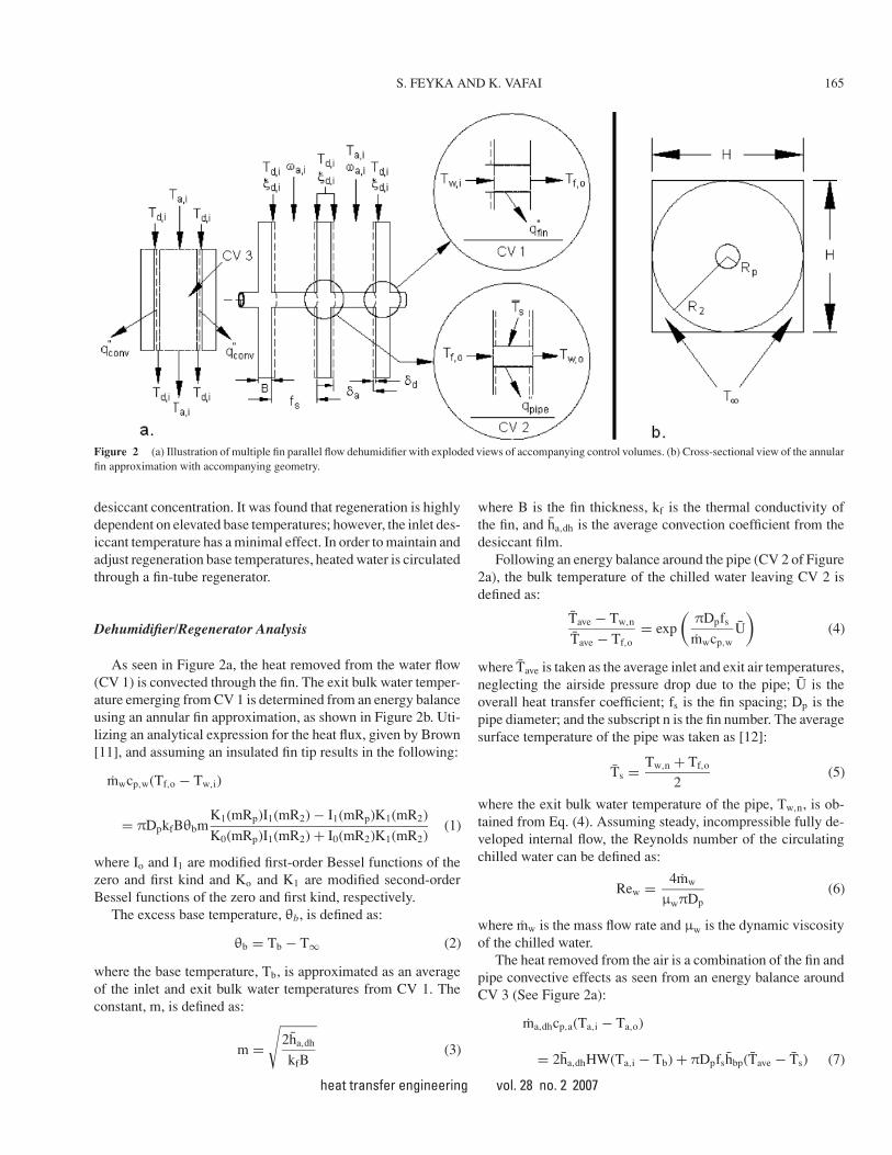
Figure 2 (a) Illustration of multiple fin parallel flow dehumidifier with exploded views of accompanying control volumes. (b) Cross-sectional view of the annularfin approximation with accompanying geometry.
desiccant concentration. It was found that regeneration is highlydependent on elevated base temperatures; however, the inlet des-iccant temperature has a minimal effect. In order to maintain andadjust regeneration base temperatures, heated water is circulatedthrough a fin-tube regenerator.
Dehumidifier/Regenerator Analysis
As seen in Figure 2a, the heat removed from the water flow(CV 1) is convected through the fin. The exit bulk water temper-ature emerging from CV 1 is determined from an energy balanceusing an annular fin approximation, as shown in Figure 2b. Uti-lizing an analytical expression for the heat flux, given by Brown[11], and assuming an insulated fin tip results in the following:
mwcp,w(Tf,o − Tw,i)
= πDpkfBθbmK1(mRp)I1(mR2) − I1(mRp)K1(mR2)
K0(mRp)I1(mR2) + I0(mR2)K1(mR2)(1)
where Io and I1 are modified first-order Bessel functions of thezero and first kind and Ko and K1 are modified second-orderBessel functions of the zero and first kind, respectively.
The excess base temperature, θb, is defined as:
θb = Tb − T∞ (2)
where the base temperature, Tb, is approximated as an averageof the inlet and exit bulk water temperatures from CV 1. Theconstant, m, is defined as:
m =√
2ha,dh
kfB(3)
where B is the fin thickness, kf is the thermal conductivity ofthe fin, and ha,dh is the average convection coefficient from thedesiccant film.
Following an energy balance around the pipe (CV 2 of Figure2a), the bulk temperature of the chilled water leaving CV 2 isdefined as:
Tave − Tw,n
Tave − Tf,o= exp
(πDpfs
mwcp,wU
)(4)
where Tave is taken as the average inlet and exit air temperatures,neglecting the airside pressure drop due to the pipe; U is theoverall heat transfer coefficient; fs is the fin spacing; Dp is thepipe diameter; and the subscript n is the fin number. The averagesurface temperature of the pipe was taken as [12]:
Ts = Tw,n + Tf,o
2(5)
where the exit bulk water temperature of the pipe, Tw,n, is ob-tained from Eq. (4). Assuming steady, incompressible fully de-veloped internal flow, the Reynolds number of the circulatingchilled water can be defined as:
Rew = 4mw
μwπDp(6)
where mw is the mass flow rate and μw is the dynamic viscosityof the chilled water.
The heat removed from the air is a combination of the fin andpipe convective effects as seen from an energy balance aroundCV 3 (See Figure 2a):
ma,dhcp,a(Ta,i − Ta,o)
= 2ha,dhHW(Ta,i − Tb) + πDpfshbp(Tave − Ts) (7)
heat transfer engineering vol. 28 no. 2 2007
166 S. FEYKA AND K. VAFAI
where W is the channel width and hbp is the airside convectioncoefficient of the bare pipe.
The convection coefficient, hc, has been correlated under lowfree stream turbulence for flow around a cylinder provided byChurchill and Bernstein [13], assuming a constant surface tem-perature, negligible flow blockage and end-effects, small tem-perature differences, and negligible free convection.
The convection coefficient for a fin-tube falling film dehu-midifier was correlated by Rahamah et al. [10] as:
ha,dh = 0.00641
(kf
Dh
)Pr1.84
a Re0.9a,dh
(H
0.6
)−0.69( fs
0.0033
)0.789
(8)
where Dh is the hydraulic diameter of the channel and H is thechannel height.
Assuming steady, incompressible, fully developed flow, theReynolds number describing the air and desiccant flow throughthe channel is defined as:
Rea = 4ma
μaW(9)
Red = 4md
μdW(10)
where μa and μd are the dynamic viscosity of air and desiccant,respectively.
Applying a moisture balance around the channel (see Figure2a), the exit humidity ratio can be determined as:
ma,dh(ωi − ωo) = 2hmaHW(ωi − ω∗) (11)
where ω is the humidity ratio of the air stream. ω∗ is the inter-facial humidity ratio [14]:
ω∗ = 0.62185pz
pt − pz(12)
where pt is the total vapor pressure (Pa). The partial vapor pres-sure of the desiccant, pz, is equal to [10]:
pz = pws
(1.0 − .828 − 1.496Z2 + Z
Tb − 40
350
)(13)
where pws is the saturated vapor pressure of water and Z is thesalt concentration of the desiccant.
From a Sherwood number correlation provided by Rahamahet al. [10], the mass convective term is defined as:
hma = 0.00641
(Ca
Dh
)Sc1.84Re0.9
(H
0.6
)−0.69( fs
0.0033
)1.197
(14)
where Sc is the Schmidt number and Ca is the diffusion coeffi-cient of air.
The exit desiccant temperature was determined from an en-ergy balance around half of the channel considering both evap-orative and convective effects at the desiccant/fin and the desic-cant/air interfaces. Using the channel centerline for symmetry,the exiting desiccant enthalpy is simply double each convective
term, as both sides of the channel are considered:
where hfg is the heat of vaporization of water and Td,i and Td,o
are the inlet and exit desiccant temperatures, respectively.A general convection coefficient from the desiccant to the fin
is given by Rahamah et al. [10] for both the dehumidificationand regeneration cases as:
hd = 0.00688kd
Dh(RedPrd)0.77 (16)
where kd is the thermal conductivity of the desiccant and Red
and Prd are the Reynolds and Prandtl numbers of the desiccant,respectively.
In addition, exit desiccant concentration predictions were ob-tained from a mass balance around the channel (see Figure 2a):
ma,dh(ωi − ωo) = 2md(ξo − ξi) (17)
where ξ is the water concentration of the desiccant and md is themass flow rate of the desiccant.
It should be noted that the inlet desiccant temperature forthe dehumidifier will tend to fall below the suggested optimalrange as it rejects heat to the regeneration desiccant stream. Asmentioned from previously published data [10], this may lead todesiccant crystallization depending on the salt concentration andtemperature of the solution. In order to stabilize localized desic-cant areas from crystallization, the proposed design includes apre-heater, which uses the ambient air to heat the desiccant backto quiescent conditions. As a consequence, the sensible load ofthe dehumidifier is also reduced, leading to slightly higher cycleefficiencies.
From an energy balance around the pre-heater (see Figure 1),the inlet air temperature to the dehumidifier is defined as:
0 = md(hd,pi − hd,po) + ma(ha,∞ − ha,po) (18)
Assuming a constant specific heat of air, the above energy bal-ance reduces to:
macp,a(Ta,po − T∞) = md(hd,i − hd,o) (19)
where T∞ is the ambient air temperature, Ta,po is the pre-heaterexit air temperature, and hd,pi and hd,po are the inlet and exitdesiccant enthalpies of the pre-heater, respectively.
Based on Eq. (11), desiccant regeneration occurs as the in-terfacial humidity ratio exceeds the humidity levels of the airstream. The exit regeneration air temperature was determinedfrom an energy balance around CV 3 (see Figure 2a):
ma,rcp,a(T∞ − Ta,o)
= 2ha,rHW(T∞ − Tb) + πDpfshbp(Tave,r − Ts,r) (20)
where Tave,r is taken as an average between the inlet and exitregeneration air temperatures, and the average pipe surface tem-perature, Ts,r, is taken from Eq. (5) for the regeneration case.
heat transfer engineering vol. 28 no. 2 2007
S. FEYKA AND K. VAFAI 167
The convection coefficient [10] for the regenerator is givenas:
ha,r = 0.00551kf
DhPr1.51
a Re0.9a,r (21)
The same basic conservation laws are applied for regenerationperformance predictions in the form of energy and mass bal-ances, starting with a moisture balance given by:
ma,r(ωo − ωi) = 2hmaHW(ωi − ω∗) (22)
The exit desiccant temperature was determined from an energybalance along the film thickness as given below:
mdcp,d(Td,o − Td,i) = 2hdHW(Tb − Td,i)
−2ha,rHW(Tb − T∞) − 2ma,rhfg(ωo − ωi) (23)
From a mass balance along the desiccant film:
ma,r(ωo − ωi) = 2md(ξo − ξi) (24)
In order to maintain cycle reliability and performance, theregenerator design is set so that the exit desiccant concentrationfrom the regenerator will regain the inlet dehumidifier condi-tion. Based on this condition, Eqs. (22) and (24) were solvedsimultaneously and equated to the definition of the interfacialhumidity ratio, as defined by Eq. (12). When combined with apartial pressure desiccant correlation based from tabulated data[15], this procedure yields the required base temperature neces-sary to satisfy the exit concentration constraint.
Chiller Modeling and Analysis
Chiller modeling (see Figure 3) and power consumption pre-dictions are based on an analysis of a vapor compression cycleoperating between the inlet and exit dehumidifier water temper-atures. As seen in Figure 3, the evaporator performs as a counter-
Figure 3 Dehumidifier section with vapor compression chiller cycle.
flow heat exchanger. The required power from the compressor,assuming isentropic and adiabatic compression, is:
Wc = mR(h2s − h1) (25)
where h2s is the isentropic exit enthalpy of the compressor (State2s of Figure 3) and mR is the refrigerant mass flow rate. Equation(25) can be expressed in terms of compressor efficiency as:
Wc = ηcmR(h2 − h1) (26)
where ηc is defined as the compressor efficiency. For this study,a nominal compressor efficiency of 80 percent is considered.
The refrigerant mass flow rate is obtained from an energybalance around the evaporator (CV 4 of Figure 3). As the re-frigerant’s cooling effect is primarily due to its phase change,complete phase change from liquid to saturated vapor is assumedunder constant temperature conditions, leading to:
mwcp,w(Tw,o − Tw,i) = mRhfg (27)
Electric Heating
The required power to the heater is determined as:
QEH = mwcp,w(Tb − Tw,ro) (28)
where Tw,ro is the exit water temperature from the regenerator.Similarly, the heat removed from the water is transferred to
the air as given from an energy balance around the regenerator,assuming that the specific heat of air remains constant:
mwcp,w(Tb − Tw,ro) = ma,r(ha,ro − ha,ri) (29)
leading to:
QEH = ma,r(ha,ro − ha,ri) (30)
where ma,r is the mass flow rate of air through the regenerator,and ha,ri and ha,ro are the inlet and exit enthalpies of air throughthe regenerator, respectively. The enthalpy of the regenerator airis defined as:
ha,r = hdry + ωahv (31)
where the enthalpy of dry air, hdry , has been correlated basedon tabulated data [16]. The enthalpy of the moisture, hv, hasbeen approximated as the enthalpy of saturated water vapor andcorrelated from tabulated data [17] for liquid water.
COP
The coefficient of performance (COP) of the proposed cyclehas been defined for a combined cycle with both work and heatadded. As the steady-flow work is proportional to the specificvolume of the desiccant, the work input from the liquid pumpsis very small and neglected in the cycle analysis. Therefore, theCOP can be approximated as:
COP ∼= QL
QEH + Wc(32)
heat transfer engineering vol. 28 no. 2 2007
168 S. FEYKA AND K. VAFAI
From an energy balance around the dehumidifier, the heat loadof the dehumidifier, QL, is the total amount of heat removedfrom the chilled water:
QL = mwcp,w(Tw,o − Tw,i) (33)
Therefore,
COP ∼= mwcp,whfg(Tw,o − Tw,i)
QEHhfg + ηcmwcp,w(Tw,o − Tw,i)(h2 − h1)(34)
RESULTS AND DISCUSSION
A parametric study is employed to investigate the overallcycle performance. Although the main focus of this investigationis to show improvements of the overall cycle efficiency (COP)as compared to a refrigeration cycle, the study also describesnominal cycle operating parameters and general cooling anddehumidification trends.
Effects of Airflow on Conditioned Air Humidity
and Temperature
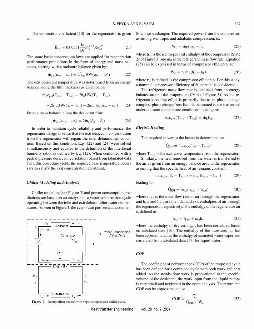
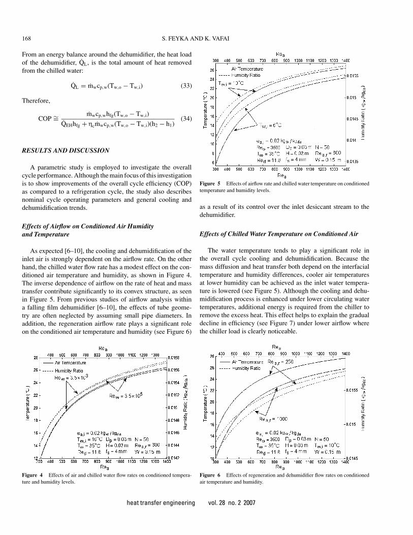
As expected [6–10], the cooling and dehumidification of theinlet air is strongly dependent on the airflow rate. On the otherhand, the chilled water flow rate has a modest effect on the con-ditioned air temperature and humidity, as shown in Figure 4.The inverse dependence of airflow on the rate of heat and masstransfer contribute significantly to its convex structure, as seenin Figure 5. From previous studies of airflow analysis withina falling film dehumidifier [6–10], the effects of tube geome-try are often neglected by assuming small pipe diameters. Inaddition, the regeneration airflow rate plays a significant roleon the conditioned air temperature and humidity (see Figure 6)
Figure 4 Effects of air and chilled water flow rates on conditioned tempera-ture and humidity levels.
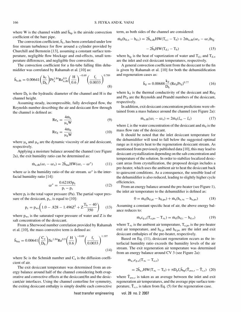
Figure 5 Effects of airflow rate and chilled water temperature on conditionedtemperature and humidity levels.
as a result of its control over the inlet desiccant stream to thedehumidifier.
Effects of Chilled Water Temperature on Conditioned Air
The water temperature tends to play a significant role inthe overall cycle cooling and dehumidification. Because themass diffusion and heat transfer both depend on the interfacialtemperature and humidity differences, cooler air temperaturesat lower humidity can be achieved as the inlet water tempera-ture is lowered (see Figure 5). Although the cooling and dehu-midification process is enhanced under lower circulating watertemperatures, additional energy is required from the chiller toremove the excess heat. This effect helps to explain the gradualdecline in efficiency (see Figure 7) under lower airflow wherethe chiller load is clearly noticeable.
Figure 6 Effects of regeneration and dehumidifier flow rates on conditionedair temperature and humidity.
heat transfer engineering vol. 28 no. 2 2007
S. FEYKA AND K. VAFAI 169
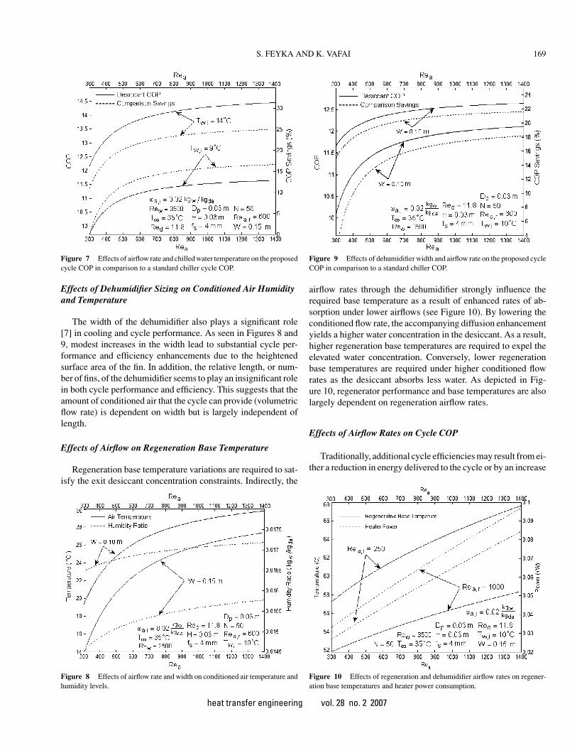
Figure 7 Effects of airflow rate and chilled water temperature on the proposedcycle COP in comparison to a standard chiller cycle COP.
Effects of Dehumidifier Sizing on Conditioned Air Humidity
and Temperature
The width of the dehumidifier also plays a significant role[7] in cooling and cycle performance. As seen in Figures 8 and9, modest increases in the width lead to substantial cycle per-formance and efficiency enhancements due to the heightenedsurface area of the fin. In addition, the relative length, or num-ber of fins, of the dehumidifier seems to play an insignificant rolein both cycle performance and efficiency. This suggests that theamount of conditioned air that the cycle can provide (volumetricflow rate) is dependent on width but is largely independent oflength.
Effects of Airflow on Regeneration Base Temperature
Regeneration base temperature variations are required to sat-isfy the exit desiccant concentration constraints. Indirectly, the
Figure 8 Effects of airflow rate and width on conditioned air temperature andhumidity levels.
Figure 9 Effects of dehumidifier width and airflow rate on the proposed cycleCOP in comparison to a standard chiller COP.
airflow rates through the dehumidifier strongly influence therequired base temperature as a result of enhanced rates of ab-sorption under lower airflows (see Figure 10). By lowering theconditioned flow rate, the accompanying diffusion enhancementyields a higher water concentration in the desiccant. As a result,higher regeneration base temperatures are required to expel theelevated water concentration. Conversely, lower regenerationbase temperatures are required under higher conditioned flowrates as the desiccant absorbs less water. As depicted in Fig-ure 10, regenerator performance and base temperatures are alsolargely dependent on regeneration airflow rates.
Effects of Airflow Rates on Cycle COP
Traditionally, additional cycle efficiencies may result from ei-ther a reduction in energy delivered to the cycle or by an increase
Figure 10 Effects of regeneration and dehumidifier airflow rates on regener-ation base temperatures and heater power consumption.
heat transfer engineering vol. 28 no. 2 2007
170 S. FEYKA AND K. VAFAI
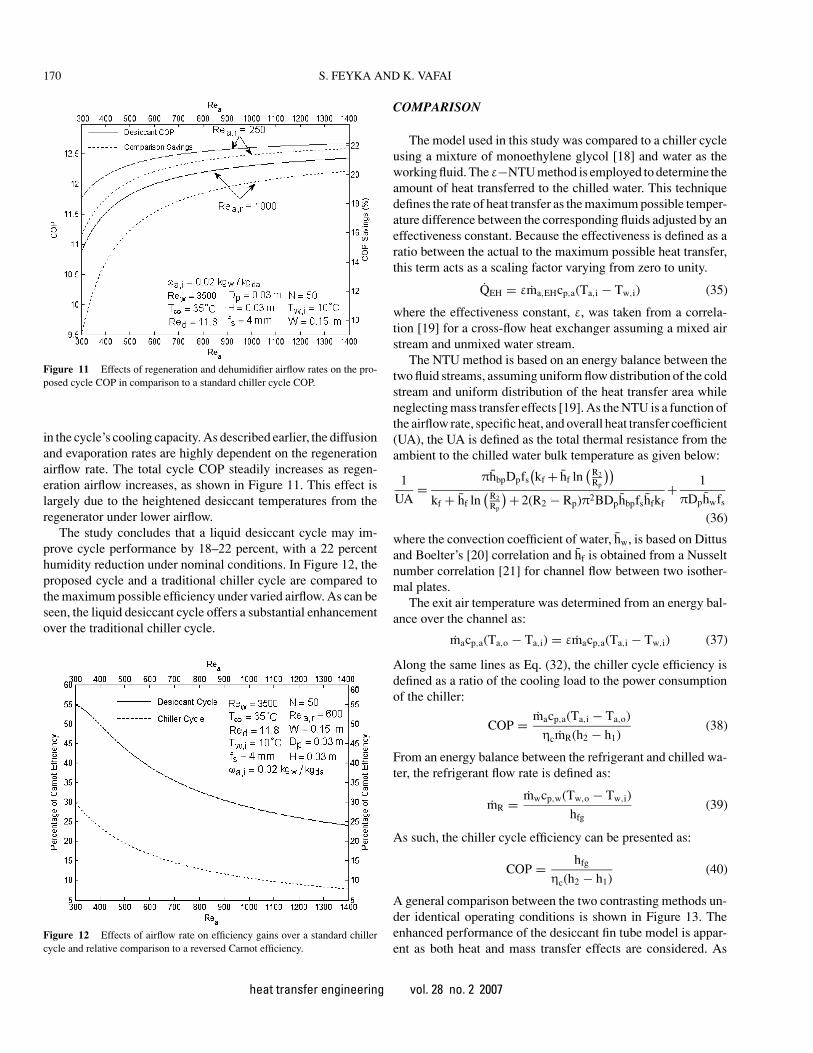
Figure 11 Effects of regeneration and dehumidifier airflow rates on the pro-posed cycle COP in comparison to a standard chiller cycle COP.
in the cycle’s cooling capacity. As described earlier, the diffusionand evaporation rates are highly dependent on the regenerationairflow rate. The total cycle COP steadily increases as regen-eration airflow increases, as shown in Figure 11. This effect islargely due to the heightened desiccant temperatures from theregenerator under lower airflow.
The study concludes that a liquid desiccant cycle may im-prove cycle performance by 18–22 percent, with a 22 percenthumidity reduction under nominal conditions. In Figure 12, theproposed cycle and a traditional chiller cycle are compared tothe maximum possible efficiency under varied airflow. As can beseen, the liquid desiccant cycle offers a substantial enhancementover the traditional chiller cycle.
Figure 12 Effects of airflow rate on efficiency gains over a standard chillercycle and relative comparison to a reversed Carnot efficiency.
COMPARISON
The model used in this study was compared to a chiller cycleusing a mixture of monoethylene glycol [18] and water as theworking fluid. Theε−NTU method is employed to determine theamount of heat transferred to the chilled water. This techniquedefines the rate of heat transfer as the maximum possible temper-ature difference between the corresponding fluids adjusted by aneffectiveness constant. Because the effectiveness is defined as aratio between the actual to the maximum possible heat transfer,this term acts as a scaling factor varying from zero to unity.
QEH = εma,EHcp,a(Ta,i − Tw,i) (35)
where the effectiveness constant, ε, was taken from a correla-tion [19] for a cross-flow heat exchanger assuming a mixed airstream and unmixed water stream.
The NTU method is based on an energy balance between thetwo fluid streams, assuming uniform flow distribution of the coldstream and uniform distribution of the heat transfer area whileneglecting mass transfer effects [19]. As the NTU is a function ofthe airflow rate, specific heat, and overall heat transfer coefficient(UA), the UA is defined as the total thermal resistance from theambient to the chilled water bulk temperature as given below:
1
UA=
πhbpDpfs(kf + hf ln
(R2Rp
))kf + hf ln
(R2Rp
) + 2(R2 − Rp)π2BDphbpfshfkf+ 1
πDphwfs
(36)
where the convection coefficient of water, hw, is based on Dittusand Boelter’s [20] correlation and hf is obtained from a Nusseltnumber correlation [21] for channel flow between two isother-mal plates.
The exit air temperature was determined from an energy bal-ance over the channel as:
macp,a(Ta,o − Ta,i) = εmacp,a(Ta,i − Tw,i) (37)
Along the same lines as Eq. (32), the chiller cycle efficiency isdefined as a ratio of the cooling load to the power consumptionof the chiller:
COP = macp,a(Ta,i − Ta,o)
ηcmR(h2 − h1)(38)
From an energy balance between the refrigerant and chilled wa-ter, the refrigerant flow rate is defined as:
mR = mwcp,w(Tw,o − Tw,i)
hfg(39)
As such, the chiller cycle efficiency can be presented as:
COP = hfg
ηc(h2 − h1)(40)
A general comparison between the two contrasting methods un-der identical operating conditions is shown in Figure 13. Theenhanced performance of the desiccant fin tube model is appar-ent as both heat and mass transfer effects are considered. As
heat transfer engineering vol. 28 no. 2 2007
S. FEYKA AND K. VAFAI 171
Figure 13 Comparison between a standard heat exchanger model and theproposed fin tube dehumidifier model.
can be seen, the general cooling trends between both methodscompare particularly well.
CONCLUSIONS
A liquid desiccant cooling cycle has been investigated andcompared to a standard chiller cycle for overall performanceand efficiency. The results under nominal values indicate that theproposed cycle has a maximum cooling capacity of 17◦C anda humidity reduction of 22 percent while boosting the overallcycle efficiency by 18–22 percent. The proposed cooling per-formance of the dehumidifier varies substantially with airflowand geometry, depending on its application. Furthermore, the fintube desiccant model compares well with similar methods usinga standard heat exchanger analysis. Although liquid desiccantcooling is relatively ineffective for required temperature reduc-tions above 20◦C, it is well suited for tropical climates withsmall diurnal temperature swings and high relative humidity.Furthermore, cycle efficiency enhancements may be achievedby using ammonia as the chiller refrigerant due to its high evap-orative energy [22], resulting in both lower conditioned air tem-peratures and overall reduction in compressor power. Additionalefficiencies may be realized, as higher performance desiccantsare selected with better absorption properties while maintain-ing low regeneration temperatures. With these additional im-provements, liquid desiccant refrigeration and freezing may bepossible while maintaining a COP above a standard vapor com-pression or chiller cycle.
NOMENCLATURE
B fin thickness, cmC diffusion coefficient, m2/scp specific heat, kJ/kg·KCV control volumeD diameter, mfs fin spacing, m
H fin height, mh enthalpy, kJ/kgh average convection coefficient, W/m2·Khfg heat of vaporization, kJ/kgk thermal conductivity, W/m·Km fin constant (m−1) defined by Eq. (3) or mass, kgm mass flow rate per unit width, kg/s · mN fin numberNTU number of units transferredp pressure, kPaPr Prandtl numberQ rate of heat transfer, kJ/sq′′ heat flux, W/m2
R radius, mRe Reynolds numberSc Schmidt numberT temperature, ◦CT average bulk temperature, ◦CUA overall heat transfer coefficient, W/◦CW channel width, mW power, kJZ salt concentration of the liquid desiccant, msalt/msolution
ξ water concentration of the liquid desiccant, mw/msolution
ρ density, kg/m3
Subscripts
a airb basebp bare pipec compressord desiccantda dry airdh dehumidifierEH electric heaterf finh hydraulici inL loadma mass transfern fin numbero outp pipe, preheaterR refrigerantr regenerator
heat transfer engineering vol. 28 no. 2 2007
172 S. FEYKA AND K. VAFAI
s surfacet totalv vaporw waterws wet saturationz salt concentration of the liquid desiccant1 saturated refrigerant vapor2 annular fin2s isentropic vapor compression3 saturated liquid refrigerant4 saturated liquid refrigerant∞ ambient
REFERENCES
[1] Howell, J. R., and Peterson, J. L., Preliminary Performance Evalu-ation of a Hybrid Vapor Compression/Liquid Desiccant Air Condi-tioning System, ASME Paper 86-WA/Sol. 9, Anaheim, California,1986.
[2] Lof, G. O. G, Cooling with Solar Energy, Proceedings of the WorldSymposium on Applied Solar Energy, Phoenix, Arizona, Novem-ber 1–5, pp. 171–189, 1955.
[3] Factor, H. M., and Grossman, G., A Packed Bed Dehumidi-fier/Regenerator for Solar Air Conditioning with Liquid Desic-cant, International Journal of Solar Energy, vol. 24, pp. 541–550,1980.
[4] Radhwan, A. M., Gari, H. N., and Elsayed, M. M., ParametricStudy of a Packed Bed Dehumidifier/Regenerator Using CaCl2
Liquid Desiccant, International Journal of Renewable Energy,vol. 3, no. 1, pp. 49–60, 1993.
[5] ASHRAE Systems and Equipment Handbook, SI ed., AmericanSociety of Heating, Refrigeration, and Air-Conditioning, Atlanta,Georgia, pp. 22.6–22.7, 1996.
[6] Park, M. S., Howell, J. R., Vliet, G. C., and Peterson, J., Numericaland Experimental Results for Coupled Heat and Mass Transferbetween a Desiccant Film and Air in a Cross Flow, InternationalJournal of Heat and Mass Transfer, vol. 37, Suppl. 1, pp. 395–402,1994.
[7] Ali, A., Vafai, K., and Khaled, A.-R. A., Analysis of Heat andMass Transfer between Air and Falling Film in a Cross FlowConfiguration, International Journal of Heat and Mass Transfer,vol. 47, pp. 743–755, 2004.
[8] Ali, A., Vafai, K., and Khaled, A.-R. A., Comparative Study be-tween Parallel and Counter Flow Configurations between Air andFalling Film Desiccant with the Presence of Nanoparticle Suspen-sions, International Journal of Energy Resources, vol. 27, no. 8,pp. 725–745, 2003.
[9] Ali, A., and Vafai, K., An Investigation of Heat and Mass Trans-fer between Air and Desiccant Film in an Inclined Parallel andCounter Flow Channels, International Journal of Heat and MassTransfer, vol. 47, pp. 1745–1760, 2004.
[10] Rahamah, A., Elsayed, M. M., and Al-Najem, N. M., A NumericalSolution for Cooling and Dehumidification of Air by a FallingDesiccant Film in Parallel Flow, Renewable Energy, vol. 13, no.3, pp. 305–322, 1998.
[11] Brown, A., Optimum Dimensions of Uniform Annular Fins,International Journal of Heat and Mass Transfer, vol. 8, no. 4,pp. 655–662, 1965.
[12] Kang, Y. T., Christensen, R. N., and Vafai, K., Analysis of Ab-sorption Process in a Smooth Tube Heat Exchanger with a PorousMedium, Heat Transfer Engineering, vol. 15, no. 4, pp. 42–55,1994.
[13] Churchill, S. W., and Bernstein, M., Correlating Equations forForced Convection from Gases and Liquids to a Circular Cylinderin Crossflow, Journal of Heat Transfer-Transactions of the ASME,vol. 99, no. 2, pp. 300–306, 1977.
[14] ASHRAE Handbook of Fundamentals, SI ed., American Societyof Heating, Refrigeration, and Air-Conditioning, Atlanta, Georgia,pp. 6.12–6.13, 1989.
[15] Dow Chemical Company, Calcium Chloride Handbook: A Guideto Properties, Storage, and Handling, Midland, Michigan, 2003.
[16] Keenan, J. H., and Keyes, F. G., Gas Tables, Wiley Press, NewYork, 1945.
[17] Keenan, J. H., Keyes, F. G., Hill, P. G., and Moore, J. G., SteamTables, Wiley Press, New York, 1969.
[19] Kays, W. M., and London, A. L., Compact Heat Exchangers, 3rded., McGraw-Hill, New York, 1984.
[20] Dittus, F. W., and Boelter, L. M. K., Publications on Engineering,vol. 2, University of California, Berkeley, California, pp. 443–461,1930.
[21] Edwards, D. K., Denny, V. E., and Mills, A. F., Transfer Processes:An Introduction to Diffusion, Convection, and Radiation, 2nd ed.,Hemisphere Publishing Corp., Washington, pp. 166–169, 1979.
[22] Haar, L., and Gallagher, J. S., Thermodynamic Properties of Am-monia, Journal of Physical Chemistry Reference Data, vol. 7,pp. 635–792, 1978.
Scott Feyka is a mechanical engineer for anaerospace subcontractor located in San Diego,California. He received his Masters degree in me-chanical engineering from the University ofCalifornia, Riverside, in 2005, and his bachelor’sdegree in Electrical Engineering from the Univer-sity of San Diego in 2002. Currently, he is a leadmechanical engineer for the development of In-tegrated Microwave Assemblies, where his spe-cialization in heat transfer and thermodynamics
plays a critical role in product modeling and analysis.
Kambiz Vafai started his university career at TheOhio State University, where he received the out-standing research award as an assistant, associate,and full professor. He has authored more thantwo hundred journal publications, book chapters,books, and edited symposium volumes, and hasbeen an invited visiting professor at the Techni-cal University of Munich in Germany, Universityof Bordeaux, and Paul Sabatier University (mul-tiple times) in France and Technical University
of Naples in Italy. He is a Fellow of ASME (1992), Fellow of AAAS (2002),Associate Fellow of AIAA (1998), and Fellow of WIF (2003). He has beenselected by the ISI among the very limited number of highly cited scientists.He has received the ASME Heat Transfer Classic Paper Award in 1999 and theHeat Transfer Memorial Award (2006). He is the editor in chief of the Journal ofPorous Media, editor of both editions of the Handbook of Porous Media, and onthe editorial board of several technical journals. He has been an associate editorof the ASME Journal of Heat Transfer. He is currently Professor of MechanicalEngineering at the University of California, Riverside.


![The role of porous media in biomedical engineering as …vafai/Publications/new/PDF Papers...Bejan [3], Vafai [4, 5], Hadim and Vafai [6] and Vafai and Hadim [7]. Significant advances](https://static.documents.pub/doc/80x56/5ac2de947f8b9ae06c8b84ac/the-role-of-porous-media-in-biomedical-engineering-as-vafaipublicationsnewpdf.jpg)


