39
An ISO-19109 Primer (and comparison to the ComplexFeature effort in GeoTools) Bryce Nordgren USDA Forest Service Page 1

An ISO19109 Primer
(and comparison to the ComplexFeature effort in GeoTools)
Bryce NordgrenUSDA Forest Service
Page 1

LegalNOTICE OF RELEASE TO THE PUBLIC DOMAIN
This work was created by employees of the USDA Forest Service's Fire Science Lab on official time funded by public money. It is therefore ineligible for copyright under title 17, section 105 of the United States Code. You may treat it as you would treat any public domain work: it may be used, changed, copied, or redistributed, with or without permission of the authors, for free or for compensation. You may not claim exclusive ownership of this work because it is already owned by everyone. Use this documentation entirely at your own risk. No warranty of any kind is given.
Complete details are provided via the US Government's public websites:
• http://www.copyright.gov/title17/92chap1.html#105
• http://www.gpoaccess.gov/uscode/ (enter "17USC105" in the search box.)
Legal Page 2

Table of ContentsLegal.......................................................................................................................................................................2Introduction.............................................................................................................................................................5Some basic definitions............................................................................................................................................6The fourlayer modeling process ..........................................................................................................................6Modeling Dynamic Features...................................................................................................................................7
ISO 19100 as a metalibrary..............................................................................................................................8Metalibrary Application Schema Services........................................................................................................8
The role of ComplexFeatures.................................................................................................................................9Requirements of an implementation.....................................................................................................................10
Real world requirements..................................................................................................................................11Common requirements....................................................................................................................................15Specification Requirements.............................................................................................................................16Summary of Needed Work on ComplexFeatures............................................................................................18
Where does the model stop?................................................................................................................................19The Eclipse Modeling Framework (EMF)..............................................................................................................20Creation of GeoAPI GFM Interfaces.....................................................................................................................20
Instantiating the GFM......................................................................................................................................21Components of the GFM............................................................................................................................21Attributes in the GFM..................................................................................................................................25Associations in the GFM.............................................................................................................................26Behavior in the GFM...................................................................................................................................27
Introduction to Ecore .......................................................................................................................................27Ecore elements...........................................................................................................................................28Ecore Inheritance, Association and Attributes............................................................................................29Ecore Behavior...........................................................................................................................................30Dynamic Ecore...........................................................................................................................................30
Prerequisite tools from ISO 19103...................................................................................................................31Multiplicity...................................................................................................................................................31Namespaces...............................................................................................................................................32Records......................................................................................................................................................33
The GeoAPI Feature Model Proposal..............................................................................................................34Proposed package: org.opengis.feature.....................................................................................................35Proposed package: org.opengis.feature.model..........................................................................................36Proposed package: org.opengis.feature.schema.......................................................................................37
ComplexFeatures as an Application Schema.......................................................................................................38Specialization of the GFM................................................................................................................................38Proposed package: org.opengis.appschema.xml............................................................................................39
Legal Page 3

Table of FiguresFigure 1: Top level categorization of the requirements.........................................................................................11Figure 2: Requirements imposed by the intended or desired use of the feature model implementation...............12Figure 3: Mapping of classes and objects in a software model of a FeatureType metamodel..............................13Figure 4: Requirements common to GIS Users and Developers..........................................................................15Figure 5: Requirements of Application Schema Designers and Implementors.....................................................17Figure 6: Application space model of the GFM MetaModel. ...............................................................................23Figure 7: Attribute Types in the Application layer model of the GFM....................................................................25Figure 8: Permissible associations in the application space model of the GFM....................................................26Figure 9: Model of behavior in the application space model of the GFM..............................................................27Figure 10: The core elements of the Ecore model................................................................................................28Figure 11: Inheritance, Association, and Attributes in the Ecore model................................................................29Figure 12: Behavioral elements of the Ecore model.............................................................................................30Figure 13: Proposal for inclusion of Multiplicity into GeoAPI.................................................................................31Figure 14: Proposal for inclusion of a NameSpace into GeoAPI...........................................................................32Figure 15: Proposal for the inclusion of Schema, Records, and RecordTypes into GeoAPI.................................33Figure 16: Proposed package: org.opengis.feature..............................................................................................35Figure 17: Proposed package: org.opengis.feature.model...................................................................................36Figure 18: Proposed package: org.opengis.feature.schema.................................................................................37Figure 19: ComplexFeatures proposal represented as an application schema....................................................38Figure 20: Proposed package: org.opengis.appschema.xml................................................................................39
Legal Page 4
IntroductionThe title of this document might lead one to believe that ISO 19109 “Geographic Information—Rules for application schema” contains some classes or interfaces which are applicable to the GeoAPI/GeoTools environment. With most other specifications, implementation is simply a matter of translating the UML diagrams more or less directly into corresponding Java interfaces and classes. But ISO 19109 is different, as it describes a metamodel framework for the definition of Features and Application Schema. As such, ISO 19109 could be implemented in GeoAPI transparently, via the implementation of other standards (e.g., 19123) which abide by the rules set forth in 19109.
This document is written as the GeoTools ComplexFeature effort draws close to release. This effort has taken place mainly to harness features of GML3 which could not be exploited under the former feature model. The resulting model includes the ability to specify inheritance, the notion of namespaces and the ability to restrict the “reported” feature instances with a filter. As such, this model is heavily driven by an implementation tied to XML and GML. For example, the proposal for inclusion into GeoAPI uses javax.xml.namespace.QName to implement namespaces1.
ISO 19109 contains many of the same concepts as the GeoAPI ComplexFeature proposal. As one can imagine, because the two efforts were carried out with no reference to each other, there are attributes from one model which are not in the other and attributes which are the same for all intents and purposes. There is, of course, the additional problem of comparing the ComplexFeature model (which is at the Application level2), with the General Feature Model (GFM) in ISO19109 (which is at the Meta level). Overall, though, the problem of comparing the two may be considered from the standpoint of trying to connect the GFM (which reaches down from the heavens of ethereal abstractions) to the ComplexFeature model (which tries to wrest abstractions out of the muck and grime of an implementation).
The GFM lays out rules for the formal modeling of features, their relationships, and their interactions. The target audience is the community of data producers, who must design an information model. It is not intended to prescribe robust software methods applicable to an environment where data are merely used. It does not describe a flexible means of discerning the data model unambiguously from the data files alone. These needs are addressed by the ComplexFeature effort, which offers absolutely no advice, help, guidelines or rules for those designing application schemas. Each has a unique intent, and the respective problem domains are almost completely complementary, if not mutually exclusive.
Even so, solutions in the two problem domains must parallel each other. The GFM does not require that compliant application schemas be machine readable (e.g., one could draw a compliant schema on the back of a napkin in a restaurant.) As such, the GFM primarily embodies metadata about the structure and behavior of data intended for a human audience. Software, on the other hand, is typically expected to handle whatever data is thrown at it, provided that it understands the format in which the data is stored. Obviously, software which is expected to handle data products resulting from the ISO 19109 design process must be capable of supporting all
1 Early feedback from Jody indicates that it is GeoAPI policy to directly reference standard java extensions whenever possible, if they provide equivalent functionality. The main question is: does javax.xml.namespace.QName provide a mapping between names and objects, which is the stated purpose of ISO19103's NameSpace.
2 The application and meta levels are described in the section “The fourlayer modeling process.”
Introduction Page 5

the features of data structures3 outlined in ISO 19109.
The intent of this document is to articulate the role played by the ComplexFeature effort with respect to ISO 19109 application schemas. The first step is to explore the fourlayer modeling process defined in ISO 19109. An understanding of the General Feature Model will be gained at the meta level. The relationship of the GFM to the standardized schemas (e.g., ISO 19123) and to finalized application schemas will be fleshed out. With this understanding of the application and meta levels of the model, we will attempt to define a relationship between the ComplexFeature effort and the GFM in terms of the role of ComplexFeature in an ISO 19109 world. Finally, this document will evaluate the ComplexFeature model in the context of its relationship to the GFM.
Some basic definitions● Application schema: a collection of feature types, their relations and behaviors which, taken together
make a complete information model of a phenomenon. (“conceptual schema for data required by one or more applications” ISO 19109)
● Conceptual model: model that defines concepts from the universe of discourse [ISO 19109]
● Conceptual schema: formal description of a conceptual model [ISO 19109]
● Feature type: an instance of GF_FeatureType in the Application layer of the four level modeling architecture. It describes the data attributes, associations with other feature types, and inheritance of a particular conceptual unit in the formalism of UML as constrained by the General Feature Model.
● Feature instance: a particular instance of a feature type. At this level, data are merely plugged into the data model which has been defined by the Feature Type.
● General Feature Model: The collection of UML classes stereotyped “<<Metaclass>>” in the Meta level of the four level architecture. Taken together, these form a general model which permits the expression of inheritance, associations, behavior, and data attributes.
● Universe of discourse: view of the real or hypothetical world that includes everything of interest.
The fourlayer modeling process The folllowing table helps explain what the term “feature” means at the four levels of the architecture. It also defines the four levels. It has been copied directly from Annex B of ISO 19109:2005(E).
3 It may never be possible to unambiguously transport behavior in a platform neutral, generic manner.
The fourlayer modeling process Page 6

Level in architecture Use of the term “feature”
Meta Meta level “feature” as the general concept, not specified being type or instance
Meta level A CLASS in the UMLexpressed General Geature Model, with the CLASSname “GF_FeatureType”
Application level A specific feature type representing a class of realworld phenomena, e.g. “Road”
an instance of the CLASS “GF_FeatureType” of the General Feature Model expressed in an application schema. The result in an application schema in UML is a CLASS called “Road”.
Data level Feature instance representing a set of data for an instance of the feature type, e.g., the road “Route 66”
Table 1: Feature used in different levelscopied from ISO 19109, Annex B.
The general concept of modeling is simple and straightforward. The “meta meta” level represents the process which transpires in your head: isolating a concept and figuring out what distinguishes one thing from another. At the Meta level, there is only one feature, and all it does is define the rules which all feature types must obey. The Application Level contains what is commonly known as a “Feature Type”. This is a formalized expression of the characteristics which were isolated in the meta meta level, and it follows the rules laid out by the meta classes of the General Feature Model. When many feature types are organized into an information model, this becomes known as an application schema. Finally, a particular instance of a feature is conveyed at the data level, using the structure defined by the application schema. Shorthand for this is the term: feature instance.
Modeling Dynamic FeaturesThe most straightforward application of ISO 19109 involves the creation of statically defined features and features organized into application schema. These features may be implemented directly by code on target platform, but all features require documentation. There are defined mappings to express the layout of the application schema in UML. ISO 19109 is primarily useful for the design of complex information models. The defined framework does not require dynamic modeling. Given the extensive attention to mapping application schemas into UML, schema could be communicated via XMI4. Alternatively, schemas could be expressed in any other standard format, like GML3.
ComplexFeatures models FeatureTypes based on data encountered at run time. It does not include a documentation capability. It can not be used to visually communicate design of application schemas. It can read what schema information is encoded in file formats which support such encoding (e.g. GML3).
The two must parallel each other if ComplexFeatures is to implement ISO 19109 features. ComplexFeatures is just an example of the implementation which every software system must perform in order to internally model a feature. The kernel of this implementation is the modeling of the “meta” layer with classes and objects. Such a ubiquitous requirement should be the topic of standardization, but is not part of ISO 19109.
4 XML Metadata Interchange (XMI) has well defined mappings to encode the content and relationships of UML diagrams. ISO 19109, in turn, supplies well defined mappings and rules to encode an application schema in UML class diagrams.
Modeling Dynamic Features Page 7

ISO 19100 as a metalibraryThus far, discussion of dynamic modeling has been constrained to data structures only. Modeling of behavior has not been proposed. The primary impediment to dynamic modeling of behavior is the lack of a single, welldefined execution environment within which to write code which implements behavior. In short, to implement an application schema on a platform, the behavioral component must be tailored to the language and library which compose the platform.
This problem succinctly encapsulates the state of crossplatform compatibility 15 years ago, when the first step in writing any program was to decide the platform for which it was intended. Any program written in C for Xwindows on SunOS was unlikely to run on a DOS machine with no GUI. The solutions to this problem in the intervening years are varied, and provide differing levels of crossplatform compatibility. Specific libraries have been written to tackle specific problems. GTK and Qt address crossplatform GUI issues. Portable threading libraries have been developed. At the extreme end of the spectrum are environments like the Java Runtime Environment, or Python, both of which strive to provide complete compatibility environments, implementing a “write once, run anywhere” capability.
The ISO 19100 series of standards is like a metalibrary which exists to address crossplatform compatibility for items of geospatial interest. This metalibrary lays out the structure for any particular instance, regardless of the implementation language or execution environment. So while a crossplatform compatibility library exists to enable code written in a single language to run in multiple execution environments, and JRE or Python each provide a single, completely synthetic environment, the metalibrary ensures that the same concepts and structure will be present in any conforming implementation, regardless of implementation language or execution environment.
Choosing to provide a metalibrary inherently describes the intended crossplatform compatibility. First, the metalibrary is a collection of geospatially useful concepts, meant to be grasped by humans, not machines. Second, any compliant execution environment will embody compatible concepts, which represent the implementation of the metalibrary's concepts in a language and using libraries appropriate to the environment. Third, any component which leverages the metalibrary could be expressed at the same level as the library (e.g., UML, using the components defined in the standards), thus adding functionality to any environment choosing to implement the userdefined component. In short, the 19100 series of standards strives to provide a common environment for geospatial development which does not require a particular OS, computer hardware, or programming language. This is accomplished by using humans to map concepts into a particular execution environment.
Metalibrary Application Schema ServicesThe metalibrary provides a metamodel of an application schema in the GFM. This metamodel specifies the construction of data structures, their relationships with one another (both associations and inheritance roles), and allows behavior to be described. In this metamodel, FeatureTypes parallel the object oriented notion of a “Class” so closely that the implementation of relationships (especially inheritance) and behavior could be completely turned over to the environment (e.g., the Java language.) Allowing the language to handle objectoriented relationships is the most straightforward way to handle inheritance, and it is hard to imagine any other way to handle behavior.
Metalibrary Application Schema Services Page 8
Explicitly modeling in software all the things that an object oriented implementation language implicitly handles is certainly not prohibited by the metalibrary. In fact, there are a number of benefits to this approach:
● Control over the object oriented model grants control over the creation of model elements. Languages like Java and C++ require a compiler to create model elements, and not all execution environments have access to a compiler.
● Control over the creation of model elements allows dynamic creation of behaviorless application schema from one or more persistence formats. This in turn permits crossplatform communication of a large part of the model5.
● Behavior is generally static. Therefore, particular behaviors may be coded separately and merged with the FeatureType after creation but before use. Note that behaviors are still specific to FeatureTypes, and still must be coded on each platform which supports that feature. The benefit is that behavior is the only part of the application schema which must be separately coded on each platform. Everything else may be (but is not required to be) automatically generated.
● The GFM is a subset of allowable objectoriented representations. It is constrained by rules which the Java or C++ compilers do not know. Explicitly implementing the model permits validation of these rules.
● And most importantly, explicit implementation of the GFM provides a common class within each execution environment for all application schema to inherit from. This is absolutely indispensable to statically typed object oriented programming languages. For these environments, explicitly modeling the GFM becomes the only workable solution.
The role of ComplexFeaturesComplexFeatures, then, would be an implementation of the GFM at the application level. As such, GeoAPI is where the GFM meets ComplexFeatures. The GFM needs to be modeled in application space as GeoAPI interfaces, and ComplexFeatures should be adapted to implement these GeoAPI interfaces.
This is not to suggest that GeoAPI/GeoTools should support more than one implementation of the GFM. ComplexFeatures is considered an implementation of the GFM because other implementations are required for other environments.
ComplexFeatures renders all the benefits of the previous section, and must provide the following functionality:
● Correctly model application schema and all relationships and behavior.
● Serve as a common object or set of objects from which all Features in the GeoAPI/GeoTools environment may inherit (or implement, in the case of an interface).
● Control the dynamic creation of application schema, feature types, and feature instances.
● Provide a stable, welldefined interface for use by an array of persistence engines. These engines may
5 Cross platform communication is possible only if the persistence formats have a standard grammar and a standard library of concepts. If XMI is used to convey the UML representation of an application schema, for instance, then the UML diagram should use the UML classes and packages defined by the metalibrary. Concepts from the metalibrary are mapped into the implementation of the local environment as the XMI file is read in. For GeoAPI/GeoTools, CV_Coverage would be mapped to org.opengis.coverage.iso.Coverage.
The role of ComplexFeatures Page 9

persist a feature instance, feature type, or an entire application schema.
● Provide the capability to merge precompiled behavior into dynamically constructed application schema. (e.g., if the client calls “execute('myfunction', parameters)” on a schema where myfunction is defined, the correct precompiled code should be run.
● Provide levels of access, controlled on a perfeature basis: (e.g., dataonly, dataandbehavior, others?) It is entirely possible that a user could download an application schema but not have an implementation of behavior for their platform.
Requirements of an implementationThe requirements of any ISO19109 compliant implementation are broken down into three main categories. These categories are a superset of the requirements of the specification itself, due to the complementary roles played by ISO19109 and ComplexFeatures. In effect, ISO19109 caters to the needs of developers of application schema and ComplexFeatures must be robust enough to dynamically generate the schema of any data source it encounters. Pragmatically speaking, these are two sides of the same coin and must receive uniform treatment.
The top level categorization of requirements is shown in Figure 1. There are requirements which only apply to users, requirements which only apply to developers, and some common requirements. Each of these categories will be fleshed out more fully in the following sections.
Requirements of an implementation Page 10

Figure 1: Top level categorization of the requirements.
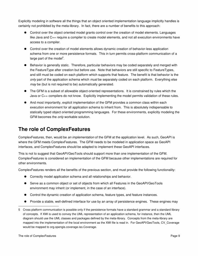
Real world requirementsReal world requirements are those requirements which are imposed by intended or desired use. These uses are fleshed out in Figure 2. The color code of the use case ovals is intended to be an evaluation of whether the ComplexFeatures implementation handles the use case or not. Green means that the use case is handled and red means that the use case is not handled. As should be expected from an implementation which grew out of immediate and pressing need, most real world uses are covered by ComplexFeatures. The weaknesses are strongly biased towards the behavioral aspects of features, which was not part of the immediate and pressing need from which ComplexFeatures grew.
The yellow box in Figure 2 is meant to represent an implementation choice. ISO 19109 permits an implementation of a feature to be coded entirely in the implementation language, without requiring a feature model at all. In this case, the implementor is required to validate their feature with the rules specified in ISO 19109, as the implementation environment contains no special knowledge of a “feature.” This choice is represented by the “Known, hardcoded features” ellipse. The gray box enclosing this option is meant to signify a rejection of this choice. Simply put, a GIS system which can only handle a predetermined set of feature types each implemented specifically in code, is useless.
The alternative to a predetermined set of hardcoded features is the implementation of some sort of feature model in the implementation language of choice. This feature model must represent the metamodel upon which
Real world requirements Page 11
it is based, and from which legal feature types may be generated. This process, however, maps the meta layer into the application layer, and in doing so, creates confusion.
Figure 2: Requirements imposed by the intended or desired use of the feature model implementation.
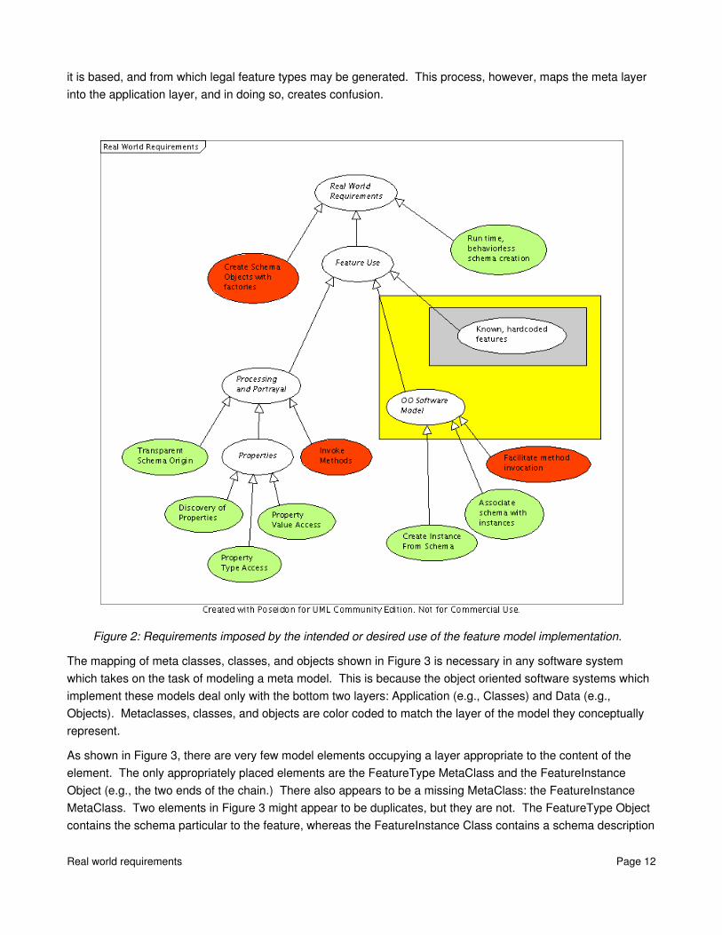
The mapping of meta classes, classes, and objects shown in Figure 3 is necessary in any software system which takes on the task of modeling a meta model. This is because the object oriented software systems which implement these models deal only with the bottom two layers: Application (e.g., Classes) and Data (e.g., Objects). Metaclasses, classes, and objects are color coded to match the layer of the model they conceptually represent.
As shown in Figure 3, there are very few model elements occupying a layer appropriate to the content of the element. The only appropriately placed elements are the FeatureType MetaClass and the FeatureInstance Object (e.g., the two ends of the chain.) There also appears to be a missing MetaClass: the FeatureInstance MetaClass. Two elements in Figure 3 might appear to be duplicates, but they are not. The FeatureType Object contains the schema particular to the feature, whereas the FeatureInstance Class contains a schema description
Real world requirements Page 12
mechanism which is configurable to any legal feature schema.
The difference between systems which merely leverage the bottom two layers embodied in object oriented languages and those which require the presence of the meta layer is the focus of Figure 3. If hard coding features were an acceptable practice, then Figure 3 would be a linear structure, with Objects instantiating Classes instantiating MetaClasses, and all elements occupying an appropriate level. Since hard coding features is not an acceptable practice, Figure 3 illustrates how model elements are displaced. It also illustrates that the metamodel is affected. The missing FeatureInstance MetaClass demonstrates that the implementation choice does make a difference at the metamodel level. Technically speaking, because the GFM is missing a FeatureInstance MetaClass, it does not permit a compliant architecture to model the meta level in software. Nevertheless, due to the sheer inappropriateness of hard coding every feature, GeoTools and GeoAPI shall model the meta level in software.
Figure 3: Mapping of classes and objects in a software model of a FeatureType metamodel.
Modeling the meta level in software will lead (and has already led) to confusion when trying to figure out how to deal with features in a general way. This is because relationships and facilities of the implementation language must be replicated by a software construct, leading to the objects which represent classes and classes which represent metaclasses. Users and implementors alike must keep in mind the distinction between what an element is and what it represents, a task which is complicated by the fact that the same set of terminology is used for both descriptions.
Dealing with data attributes is relatively straightforward to model, as FeatureType Objects own a configured schema of types and FeatureInstance Objects own a configured schema of values. Modeling of behavior is a topic of concern, however. A description of behavior is straightforward to model, as it is just another property of the feature. Implementation of behavior requires a compiler, as this is one aspect of the application schema which cannot be modeled. In fact, it is fair to say that implementation of behavior is not part of an application schema described by the GFM. Unfortunately, any application schema implementation requires implementations of behaviors to be merged with the descriptions of behaviors in the application schema. This is
Real world requirements Page 13
FeatureType MetaClass
Data(Objects)
Application(Class)
Meta(Metaclass)
Meta Meta
FeatureType Class
FeatureType Object
FeatureInstance Class
No structure
FeatureInstance Object
the hard part.
Note that the discussion thus far has not assumed a particular development environment. The problems encountered thus far are mainly conceptual and would be encountered by every statically typed object oriented programming environment of which I am aware6. Thus, this would seem to merit treatment by the standard by creating a recommended instance of the metamodel at the application layer, and adding the FeatureInstance MetaClass to the metamodel.
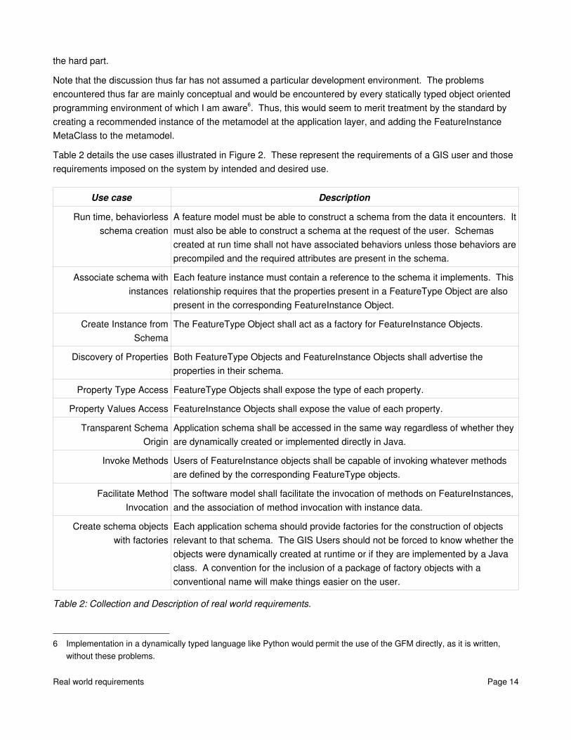
Table 2 details the use cases illustrated in Figure 2. These represent the requirements of a GIS user and those requirements imposed on the system by intended and desired use.
Use case Description
Run time, behaviorless schema creation
A feature model must be able to construct a schema from the data it encounters. It must also be able to construct a schema at the request of the user. Schemas created at run time shall not have associated behaviors unless those behaviors are precompiled and the required attributes are present in the schema.
Associate schema with instances
Each feature instance must contain a reference to the schema it implements. This relationship requires that the properties present in a FeatureType Object are also present in the corresponding FeatureInstance Object.
Create Instance from Schema
The FeatureType Object shall act as a factory for FeatureInstance Objects.
Discovery of Properties Both FeatureType Objects and FeatureInstance Objects shall advertise the properties in their schema.
Property Type Access FeatureType Objects shall expose the type of each property.
Property Values Access FeatureInstance Objects shall expose the value of each property.
Transparent Schema Origin
Application schema shall be accessed in the same way regardless of whether they are dynamically created or implemented directly in Java.
Invoke Methods Users of FeatureInstance objects shall be capable of invoking whatever methods are defined by the corresponding FeatureType objects.
Facilitate Method Invocation
The software model shall facilitate the invocation of methods on FeatureInstances, and the association of method invocation with instance data.
Create schema objects with factories
Each application schema should provide factories for the construction of objects relevant to that schema. The GIS Users should not be forced to know whether the objects were dynamically created at runtime or if they are implemented by a Java class. A convention for the inclusion of a package of factory objects with a conventional name will make things easier on the user.
Table 2: Collection and Description of real world requirements.
6 Implementation in a dynamically typed language like Python would permit the use of the GFM directly, as it is written, without these problems.
Real world requirements Page 14
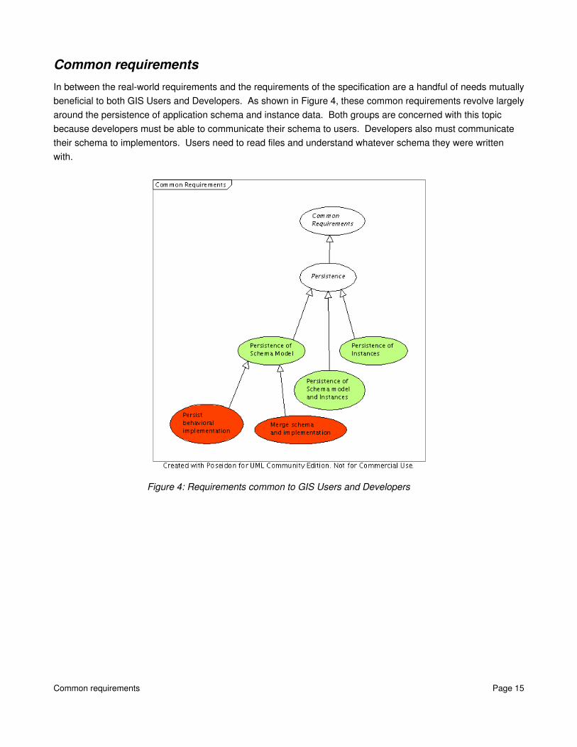
Common requirementsIn between the realworld requirements and the requirements of the specification are a handful of needs mutually beneficial to both GIS Users and Developers. As shown in Figure 4, these common requirements revolve largely around the persistence of application schema and instance data. Both groups are concerned with this topic because developers must be able to communicate their schema to users. Developers also must communicate their schema to implementors. Users need to read files and understand whatever schema they were written with.
Figure 4: Requirements common to GIS Users and Developers
Common requirements Page 15

Use Case Description
Persistence of instances The framework shall be capable of persisting instances without explicitly describing the schema. Conversely, a read operation must deduce the schema from the instance or merge a schema in with the data. This is also a mechanism to describe a schema which includes relationships between traditional, “flat” feature types, thus adding a higher level of organization.
Persistence of Schema Model The framework shall be capable of persisting the schema separately from instance data.
Persistence of Schema Model and Instances
The framework shall be capable of persisting both schema and model.
Persist behavioral implementation
Implementations of behavior in the GeoTools/GeoAPI environment shall be packaged Java code amenable to being merged with the description of behavior in the application schema.
Merge schema and implementation
The feature model shall associate the supplied implementation of behavior with the description of behavior in the application schema. This process enables the invocation of the behavior on the instance data.
Table 3: Description of requirements common to GIS Users and Developers
Specification RequirementsRequirements of the specification caters primarily to the needs of the developers of application schema. Functionally, it defines the characteristics which a compliant feature model must support. As shown in Figure 5, the ComplexFeature model does not include support for feature behavior, feature associations, or organization into feature libraries, but does support constraints, inheritance, and attributes.
Specification Requirements Page 16
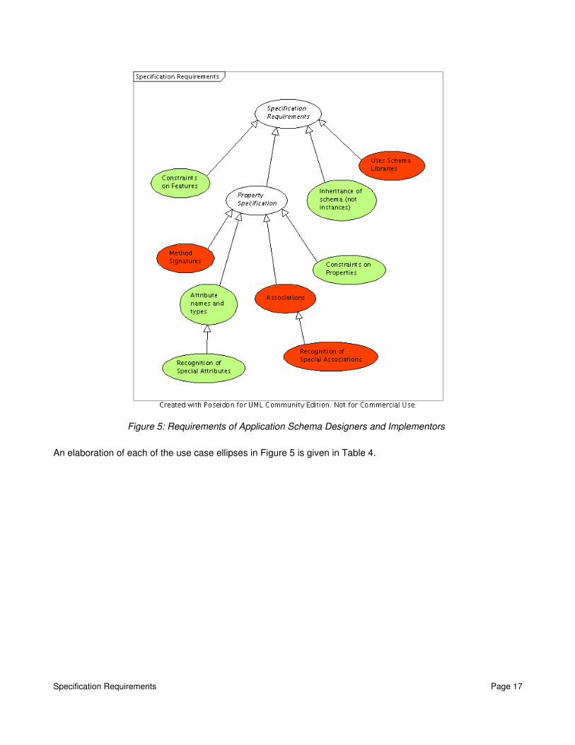
Figure 5: Requirements of Application Schema Designers and Implementors
An elaboration of each of the use case ellipses in Figure 5 is given in Table 4.
Specification Requirements Page 17

Use case Description
Constraints on Features The model shall be capable of implementing constraints on features.
Constraints on Properties The model shall be capable of implementing constraints on properties (attributes, behaviors, and associations)
Inheritance of schema (not instances)
The model shall ensure that schema in FeatureType Objects properly reflects the inherited properties from the parents. FeatureInstance Objects do not exhibit inheritance relationships, but their schema must correspond to the associated FeatureType Object.
Uses schema libraries The model shall be capable of assembling application schemas (or fragments thereof) into libraries for subsequent use.
Method Signatures The model shall be capable of indicating that a feature possess behavioral properties and shall be capable of describing that behavior in natural language or in a language appropriate to the implementation environment.
Attribute names and types The model shall be capable of specifying the names and types of attributes.
Recognition of special attributes
The model shall recognize the following special categories of attributes: temporal, spatial/geometric, spatial/topological, locations (e.g., gazetteer entries), metadata, metadata/data quality, and “thematic” (e.g., everything else).
Associations The model shall be capable of specifying associations between data sets.
Recognition of special associations
The model shall recognize at least the following special categories of associations: aggregation, spatial, and temporal.
Table 4: Requirements of the specification and of application schema developers.
Summary of Needed Work on ComplexFeaturesThis section has developed a set of requirements any feature model must implement in order to provide an acceptable level of service to clients which need features to possess attributes, associations, and methods. A major requirement of the acceptable level of service constraint is the dynamic creation and manipulation of feature types. Another major requirement is to support the application of feature behavior to the correct instance of feature data. Finally, access to feature attributes, associations, and behaviors must be transparent to the user: feature types may be modeled or may be directly implemented, but clients shouldn't know the difference. In essence, this section defines the characteristics of the Holy Grail of feature models with which it is possible to do anything which is possible in the implementation environment.
The red ellipses throughout this section indicate the requirements that the ComplexFeatures model does not currently support. A feature model implementation does not have to satisfy all these requirements right away, but to be used as a base for the implementation of coverages it must implement the behavioral aspects. So, if the coverage effort is to be modeled as a feature using the ComplexFeatures implementation, a behavioral capability must be added to the model.
This is not without its fair share of perils. Handling behavior correctly may take quite a bit of tinkering. The
Summary of Needed Work on ComplexFeatures Page 18
feature instance needs to hark back to the feature type in order to determine which behaviors it possesses. Then the feature instance data object must be provided to the implementation in the feature type object. This is normally handled automatically by the execution environment, but must now be performed in software. I have not thought this fully through yet, but it seems nontrivial.
Where does the model stop?
A wellknown scientist (some say it was Bertrand Russell) once gave a public lecture on astronomy. He described how the Earth orbits around the sun and how the sun, in turn, orbits around the centre of a vast collection of stars called our galaxy.
At the end of the lecture, a little old lady at the back of the room got up and said: "What you have told us is rubbish. The world is really a flat plate supported on the back of a giant tortoise."
The scientist gave a superior smile before replying, "What is the tortoise standing on?"
"You're very clever, young man, very clever," said the old lady. "But it's turtles all the way down."
http://en.wikipedia.org/wiki/Turtles_all_the_way_down(the version in Hawking's A Brief History of Time).
At some point between the UML class diagrams and the microprocessor's instruction fetch cycles, a model becomes an implementation. At this line, wherever it may be, it becomes necessary to refer to something which is not modeled in order to effect an action. The requirements in the previous section attempt to make the line fuzzy by specifying implementations of behavior separately from description of behavior. However, at some point, the execution of code will wander out of the carefully constructed and configurable feature model and into pure Java classes7. In fact, this will occur every time a feature's behavior is invoked.
This leads us directly back to the question of the relationship between coverages and features. ISO 19123 specifies coverage types as instances of the GF_FeatureType metaclass. Obviously, the expression of the coverage schema is performed in terms of classes in class diagrams. But our implementation environment is modeling the meta layer. Should coverages be modeled by the feature model or should they be instantiated directly as a separate Java classes, negating the advantages of having a common point in the class hierarchy? On which side of the line does the coverage schema lie?
Coverages are features which have a lot of behavior. Clearly, if coverages are to be modeled, implementation and use of coverages will be facilitated with a clean, efficient, and obvious means of treating behavioral components of features. Ideally, implementing and using a modeled coverage should be no different than using a hardcoded coverage. Practically, though, one must realize that the ideal will not be achieved.
So on the one hand, implementing coverages directly as Java classes provides clean, natural and direct access to all of the properties of a feature (including behavior), but breaks the clean class hierarchy by effectively treating a “coverage feature” as a data structure. On the other hand, modeling coverages keeps the class
7 Some might argue that this is merely a different model.
Where does the model stop? Page 19

hierarchy clean at the possible expense of efficiency, convenience, and maintainability. Both alternatives have very appealing pros and very discouraging cons.
The Eclipse Modeling Framework (EMF)Modeling the meta level in software is the only problem facing feature model implementation. Fortunately, it is not a problem unique to the modeling of features and so has been solved by others. The Eclipse Modeling Framework (http://www.eclipse.org/emf/) has been designed to solve exactly this problem. The EMF is mature, being the evolution of the XML Toolkit from IBM's Alphaworks labs. The EMF is separable from the Eclipse universal tool platform, within which it can run. It has a number of attractive features, summarized succinctly as follows:
● It is mature code actively maintained by someone else.● It supports the dynamic creation of models (features) at runtime (an absolute requirement).● It supports relationships between features, and generated code automatically maintains referential
integrity.● It has a “merging” code generator.
Code which is manually modified can be marked “off limits” to the generator within the source, by deleting a tag in the Javadocs. The same class may contain modeled and directly implemented components (e.g., the modeling granularity is at the property level, not at the class level.)
● It provides uniform access to properties and property discovery services to clients. Clients do not need to know whether the “class” is a Real Java Class or Just a Model. The EMF provides transparent access to both, and expects to be forced to deal with some combination of both.
● It can (de)serialize the model to(from) Java code, XML Schema, or XMI.● It can (de)serialize model instances to(from) XML (corresponding to the generated XML Schema) or
XMI.● It has a convention for the (optional) creation of singleton factories to support creation of all modeled
elements. This convention is configurable.● The reflective API is supposed to be faster than standard Java reflection.● The current model (application schema) can refer to external models (standard schemas) to include
model elements defined elsewhere (and stored in model libraries).
To summarize, if the EMF does indeed embody all of the capabilities required for the modeling of the coverage schema (backed, of course, by a concrete Java implementation), it may be the solution we didn't know we were looking for. Coverages may be modeled as features, they may be backed with a concrete implementation, and anything “upstream” which attempts to handle features in a generic way will be capable of addressing ComplexFeatures, SimpleFeatures, and Coverages in a uniform manner.
Creation of GeoAPI GFM InterfacesThe creation of GeoAPI interfaces to represent a GFM instance will occur in two steps. The first step involves the creation of an application layer model which can represent the GFM in software. The second step is the generation of interfaces from this application layer model.
Creation of GeoAPI GFM Interfaces Page 20

Instantiating the GFMThis section will show that someone (most likely me) does not understand what a metamodel is or how to use it. My current understanding is that a metaclass is to a class like a class is to an object. Therefore, metaclasses have instances which are classes, and from there objects are created like normal. This section is based on that understanding. In Figure 6 through Figure 9, I have instantiated all the various aspects of the feature metamodel. This is a reasonably straightforward process and involves some minor editing either to correct perceived errors or to make the model less unwieldy. The goal of this effort is to arrive at a model in application space which permits the dynamic construction of legal features inside the implementation environment.
Unfortunately, this point of view has been systematically contradicted by the rules for applying the metamodel to a UML model. These rules combine to permit a more “natural” UML expression of features at the application level. For instance, the literal implementation of the feature model in Figure 6 would indicate that attributes are a type of feature property, and all properties are held in a composition named “carrierOfCharacteristics”. So to get at an attribute by following the rules I understand, one needs to ask the “carrierOfCharacteristics” composition for a member of the appropriate name. The rules in Clause 8 of the spec simply declare that an alternate representation at the application level is the only valid representation, in this case, “An instance of GF_AttributeType shall be implemented as an ATTRIBUTE...” As previously indicated, this leads to a much more natural UML representation of feature types.
Behavior, as always, is the sticking point. Accepting that the rules specify how elements of the metamodel map to the applicationlevel representation, it is easy to see that the capabilities and constraints of the metamodel are accounted for by the mapping. For everything, that is, except behavior. My model of behavior in Figure 9 falls tragically short of representing the power and flexibility of the mapping rule: “An instance of GF_Operation shall be implemented as an OPERATION of the class representing the feature type that it characterizes, which shall have ASSOCIATIONS to other CLASSES from which the operation needs ATTRIBUTE VALUES.” There are a number of capabilities not modeled by Figure 9 which are permitted by the mapping rule, chief among them are: 1] return values; and 2] parameters. It is not possible to model the behavior permitted by the rule with the supplied metamodel.
To summarize, this section represents an early effort to explore the GFM meta model as the basis for building a feature model in software from scratch. For the most part, instantiating the GFM directly into the application layer appropriately represents the capabilities permitted by the mapping rules. Behavior is the exception, and extensive modification to Figure 9 is required before it represents the capabilities embodied in the only permitted UML representation8. In all, if a software model were to be built from scratch, the diagrams in this section provide a good picture of what it must look like.
Components of the GFMTODO: Ponder the role of metadata. As the GFM migrates from the meta level to the application level, does the metadata follow? If it follows, it must become optional...
8 This represents a flaw in the standard, as capabilities should be defined by the metamodel and implemented by the mapping rules. For the case of behavior, the mapping rule defines capabilities absent in the metamodel, and these mappingrulecapabilities are already exploited in the coverage schema to define methods with parameters and return values.
Components of the GFM Page 21

The following series of figures are highly derivative from the General Feature Model defined in the ISO19109 standard. This is to be expected as they represent an implementation of said model in software. The four figures in the series represent a first cut at designing an implementation of that model. As such, they represent less information than could be gleaned from the Javadocs of a completed implementation. More to the point, these four modified figures removed from the context of the 70 pages of accompanying documentation sit firmly in the realm of “fair use”. So if you want to know more, or if you'd like to deal directly with the source instead of being forced to read my interpretation of TC/211's intent, go buy the standard.
Components of the GFM Page 22

Figure 6: Application space model of the GFM MetaModel.
If we assume that we do not adopt the EMF as the GeoTools feature model, we are still forced to adopt or construct a model capable of expressing features at the application layer. Figure 6 represents a decent first cut at expressing the metamodel in the application layer. It is substantially similar to Figure 5 in ISO19109, but has been “ported” to the application layer. The package identifiers have been changed from GF to FM, to avoid
Components of the GFM Page 23

confusion with the metamodel. Notable changes for implementation purposes include the addition of a FM_FeatureInstance class, inheritance of FM_FeatureType and FM_FeatureInstance from RecordType and Record, respectively, FM_Constraint has been made abstract and given a single abstract method, and the omission of GF_InheritanceRelation, which will be dealt with later (and which has also been changed, but might be changed back).
This figure models:
● Multiple inheritance● Properties of a feature type
Data attributesOperation and behaviorAssociation roles
● Association types (distinct from association roles)
Components of the GFM Page 24
Attributes in the GFM
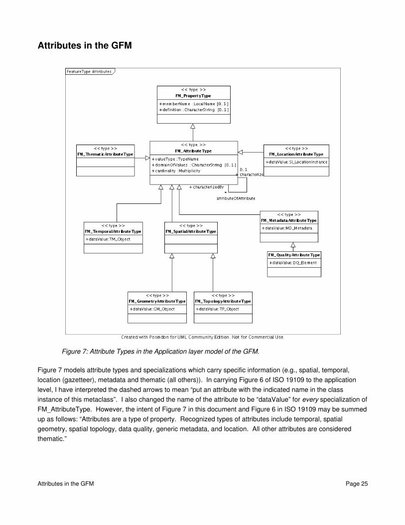
Figure 7: Attribute Types in the Application layer model of the GFM.
Figure 7 models attribute types and specializations which carry specific information (e.g., spatial, temporal, location (gazetteer), metadata and thematic (all others)). In carrying Figure 6 of ISO 19109 to the application level, I have interpreted the dashed arrows to mean “put an attribute with the indicated name in the class instance of this metaclass”. I also changed the name of the attribute to be “dataValue” for every specialization of FM_AttributeType. However, the intent of Figure 7 in this document and Figure 6 in ISO 19109 may be summed up as follows: “Attributes are a type of property. Recognized types of attributes include temporal, spatial geometry, spatial topology, data quality, generic metadata, and location. All other attributes are considered thematic.”
Attributes in the GFM Page 25
Associations in the GFM
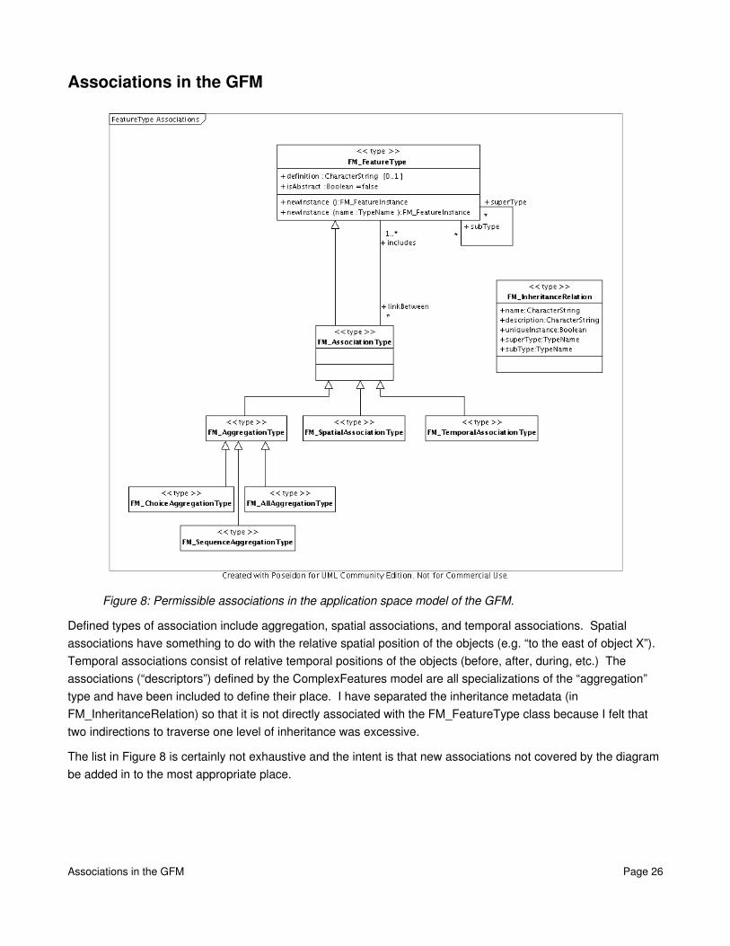
Figure 8: Permissible associations in the application space model of the GFM.
Defined types of association include aggregation, spatial associations, and temporal associations. Spatial associations have something to do with the relative spatial position of the objects (e.g. “to the east of object X”). Temporal associations consist of relative temporal positions of the objects (before, after, during, etc.) The associations (“descriptors”) defined by the ComplexFeatures model are all specializations of the “aggregation” type and have been included to define their place. I have separated the inheritance metadata (in FM_InheritanceRelation) so that it is not directly associated with the FM_FeatureType class because I felt that two indirections to traverse one level of inheritance was excessive.
The list in Figure 8 is certainly not exhaustive and the intent is that new associations not covered by the diagram be added in to the most appropriate place.
Associations in the GFM Page 26

Behavior in the GFM
Figure 9: Model of behavior in the application space model of the GFM.
This figure proposes a model for describing behavior. The methods it describes do not have return types, but they may observe, affect, and be triggered by values of the feature's attributes.
Introduction to Ecore The heart of the Eclipse Modeling Framework is called Ecore. “Ecore defines the structure of core models, which in turn define the structure of models we use to maintain application data,” says the EMF Bible9. The EMF shares a common heritage with ISO 19109, as both inherit much of their structure from MOF and UML. For instance, both ISO19109 and Ecore gather attributes into a composition of the class which owns them. Both provide identical mappings from the metamodel representation to representation on a class diagram (or in a Java class.) ISO 19109 states that all subclasses of GF_AttributeType shall be represented as attributes of the class which contains them. Ecore will make the identical translation when generating Java classes from the model. Ecore, however, has appropriately expressed the metamodel such that “operations” are permitted to have return types and parameters. Ecore also has a cleaner expression of bidirectional association pairs. The main shortcoming of Ecore with respect to ISO 19109 is that it only permits navigation of the “Feature Hierarchy” from the children to the parents.
9 The definitive reference is Eclipse Modeling Framework by Frank Budinsky, et. al. It is colloquially known as the EMF Bible.
Introduction to Ecore Page 27
Thus, features may be constructed and expressed in terms of the Ecore model, provided that an accepted mapping from ISO19109 concepts to Ecore concepts is established.
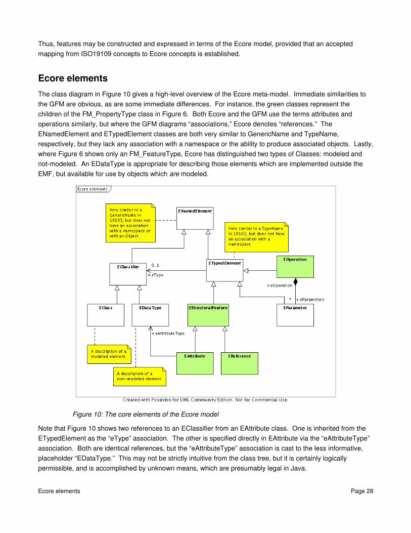
Ecore elementsThe class diagram in Figure 10 gives a highlevel overview of the Ecore metamodel. Immediate similarities to the GFM are obvious, as are some immediate differences. For instance, the green classes represent the children of the FM_PropertyType class in Figure 6. Both Ecore and the GFM use the terms attributes and operations similarly, but where the GFM diagrams “associations,” Ecore denotes “references.” The ENamedElement and ETypedElement classes are both very similar to GenericName and TypeName, respectively, but they lack any association with a namespace or the ability to produce associated objects. Lastly, where Figure 6 shows only an FM_FeatureType, Ecore has distinguished two types of Classes: modeled and notmodeled. An EDataType is appropriate for describing those elements which are implemented outside the EMF, but available for use by objects which are modeled.
Figure 10: The core elements of the Ecore model
Note that Figure 10 shows two references to an EClassifier from an EAttribute class. One is inherited from the ETypedElement as the “eType” association. The other is specified directly in EAttribute via the “eAttributeType” association. Both are identical references, but the “eAttributeType” association is cast to the less informative, placeholder “EDataType.” This may not be strictly intuitive from the class tree, but it is certainly logically permissible, and is accomplished by unknown means, which are presumably legal in Java.
Ecore elements Page 28

Ecore Inheritance, Association and AttributesInheritance in the Ecore model, as shown in Figure 11, is comprised of the two selfreferential associations “eAllSuperTypes” and “eSuperTypes.” The effect of these associations is to permit navigation of the class tree from any given modeled class back to the root object. Navigation in the opposite direction is not permitted. This is the single biggest shortcoming of the Ecore model when viewed from the perspective of implementing the GFM. Augmenting Ecore to permit bidirectional traversal of the class tree is not likely to be useful enough to merit the effort, so this will be postponed for future work.
Figure 11: Inheritance, Association, and Attributes in the Ecore model.
As shown, the EStructuralFeature class occupies the same place in the class tree of Figure 11 as FM_PropertyType does in Figure 6. It plays the role of gathering together associations and attributes under one umbrella. The difference is how Ecore handles operations. An operation is not a sibling of associations and attributes, as it is one level higher in the class tree. The EClass divides provides three separate compositions to implement the “carrierOfCharacteristics” composition in Figure 6: “eReferences” (for associations), “eAttributes” (for attributes), and “eOperations” (for Operations).
An EClass provides access to properties (meaning attributes, associations, and operations) defined in the current class separately from access to all properties both defined and inherited. This separation is present in a pattern of two directed associations from EClass to EAttribute, EOperation, and ERreference. Each of these properties of an Eclass has one association with an “eXXX” role name, and one with an “eAllXXX” role name
Ecore Inheritance, Association and Attributes Page 29

(where XXX is one of Attributes, Operations, or References.) EClass does combine associations and attributes into a single, derived role name: “eAllStructuralFeatures,” but it must be remembered that this omits the operations properties. When determining whether a property is present or not, one must remember to check the appropriate “eAllXXX” association, as this includes all the properties inherited by the EClass.
Ecore BehaviorOf the models investigated so far, Ecore is the only one which not only handles behavior properly, but is an implementation which has received widespread use and testing. There is nothing like a software release to discover bugs. One may assume that a mature package like Ecore is at least functional, and has probably suffered the removal of “features” which make the package awkward to use.
Figure 12: Behavioral elements of the Ecore model.
As shown in Figure 12, the relationship between EClass and EOperation possesses the same duality as associations and attributes. Namely, one may retrieve only the operations defined in this class, or one may obtain a list of all operations, both defined and inherited. An operation may throw an exception. It may contain parameters. It may have a return type (e.g., the type indicated via its inheritance from EtypedElement.)
The functionality shown in Figure 12 demonstrates how to model what is lacking in Figure 9. It is quite likely that the Ecore model accurately represents the intent of the GFM. The rule for mapping a GF_Operation to UML neglects to prohibit operations with return types or parameters. However, the mapping from either model to UML (and hence to Java) is the same: implement an operation as a method of the class. Regardless of what lies behind the scenes, the effect is the same.
Dynamic EcoreIf Ecore were completely static, there would be no benefit to using it to model features. After all, the model behind java.lang.Class is very similar to both Ecore and the GFM. Likewise, if we were only using the static code generation parts of EMF, there would be no need to learn anything about the model. The model understands itself. It can read Java interfaces and map to its own internal conceptual model without assistance.
Dynamic Ecore Page 30

Users of static EMF could get by without learning anything about Ecore at all.
Learning the model which backs EMF is only useful if a different method of constructing an application schema is desired. Dynamic creation of an application schema at runtime is an example of just such a situation. As features are just EClasses, one must learn how to programmatically create an EClass. Then one must learn how to add attributes of the desired type. Finally, if clients accesses the attributes using Ecore's reflective API, they are unaffected by differences in creation method: they may access attributes of a dynamically created EClass in exactly the same manner they access attributes of a coverage, which will be implemented with Java code.
TODO: Create a figure which shows the model for packages and factories. Explain the common pattern of getting the package to which the EClass belongs, getting the factory for that package, and then instantiating objects from the EClass. Note that EMF should handle the case where dynamic classes extend generated ones.
Prerequisite tools from ISO 19103The ISO/TC 211 metalibrary contains quite a few fundamental building blocks upon which more advanced structures are based. This library is vertically integrated in the sense that complex items like features are built from simpler concepts. The tools required for building a feature are: a notion of multiplicity; a namespace; and the concept of records. In the following sections, a proposed set of interfaces is advanced for each of these topics. An explanation of the need for the addition to GeoAPI accompanies each proposal. It should be stressed, however, that the use of these fundamental tools is not limited to the immediate usage I point out within these pages.
MultiplicityMultiplicity is a basic tool needed to specify a required characteristic of attributes and associations. This is a very simple tool which consists of two interfaces and should be self explanatory. This tool is documented in Figure 13.
Figure 13: Proposal for inclusion of Multiplicity into GeoAPI
Multiplicity Page 31

NamespacesThe current definition of namespaces in GeoAPI is QName. This is an XML implementation of namespaces and does not correspond with the purpose and functionality of the NameSpace defined in 19103. As defined in 19103, a namespace exists to form an association between names and objects, and to serve as a dictionary to retrieve an object based on the name. Names may have scopes. QName lacks the concept of aggregation into a dictionary and also lacks the association of a name with an object.
Pragmatically speaking, the structure of Figure 14 parallels the structure of the Ecore model of class properties. LocalName is related to ENamedElement in Figure 10. MemberName is related to a TypedElement, and EClassifier is related to TypeName. Implementing namespace as specified by 19103 facilitates the expression of the GFM in terms of TC211 standardized schema.
Figure 14: Proposal for inclusion of a NameSpace into GeoAPI.
Namespaces Page 32
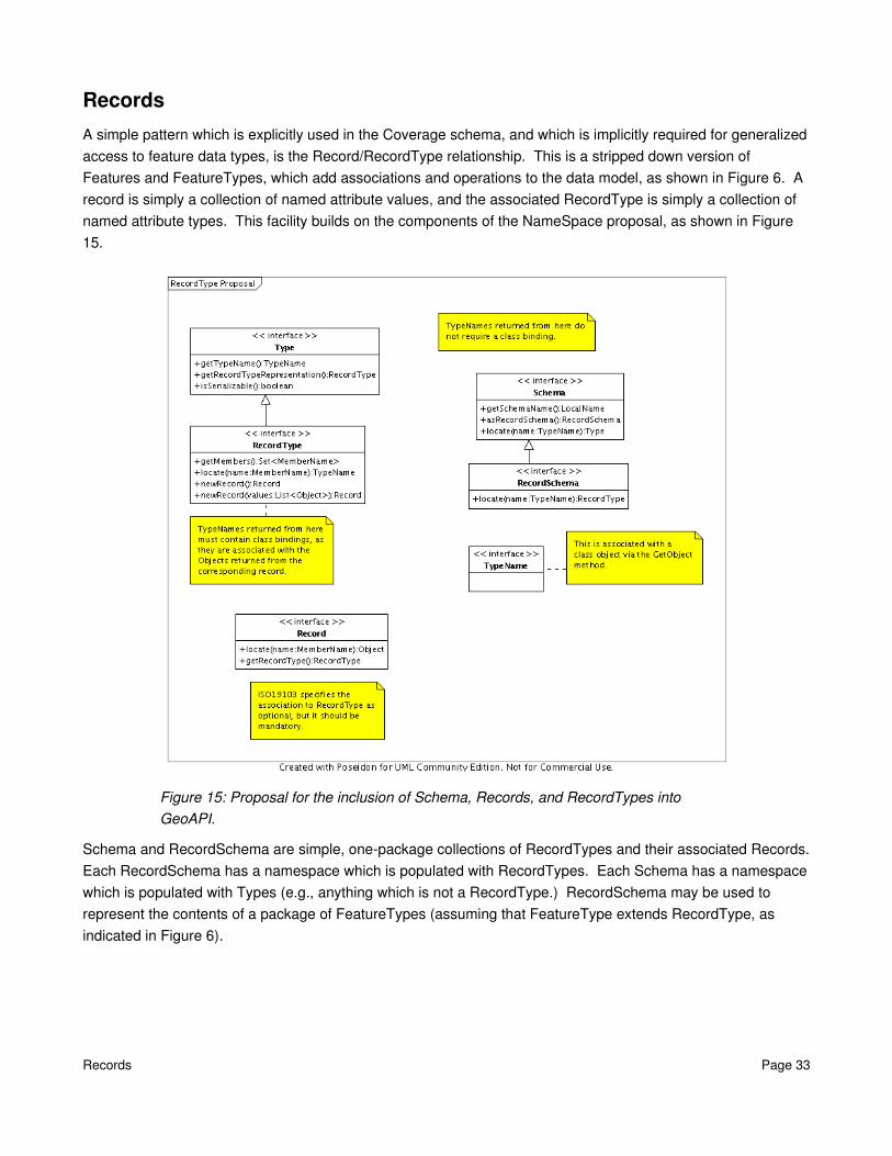
RecordsA simple pattern which is explicitly used in the Coverage schema, and which is implicitly required for generalized access to feature data types, is the Record/RecordType relationship. This is a stripped down version of Features and FeatureTypes, which add associations and operations to the data model, as shown in Figure 6. A record is simply a collection of named attribute values, and the associated RecordType is simply a collection of named attribute types. This facility builds on the components of the NameSpace proposal, as shown in Figure15.
Figure 15: Proposal for the inclusion of Schema, Records, and RecordTypes into GeoAPI.
Schema and RecordSchema are simple, onepackage collections of RecordTypes and their associated Records. Each RecordSchema has a namespace which is populated with RecordTypes. Each Schema has a namespace which is populated with Types (e.g., anything which is not a RecordType.) RecordSchema may be used to represent the contents of a package of FeatureTypes (assuming that FeatureType extends RecordType, as indicated in Figure 6).
Records Page 33

The GeoAPI Feature Model ProposalThe GFM and Ecore are two nearly identical models which both have one extremely desirable characteristic: most users will not need to be exposed to the complexities of the model! A user who receives a pregenerated Feature (e.g., from a data source), and who uses only the generic accessor methods, need only learn get/setAttribute(name) and get/setAssociation(name, value). (The basic difference between these two being that associations may only return FeatureTypes and attributes may return anything.) Users who need to do some basic reflection need to learn about a FeatureType. Advanced reflection supplies enough information to draw a correct UML diagram of the application schema, or give information on the resolution of proxy references.
This proposal is strongly influenced by the structure of the Ecore model, which is extremely similar to the GFM. A fraction of Ecore's full modeling vocabulary is harnessed, but the full expressive power of the GFM is represented. In the case of behavior, Ecore's representation was favored over the GFM's representation because the GFM's representation was just not capable of representing all the functionality of the rule which maps operations to UML.
However strongly influenced by Ecore this model is, it is still an implementation and we do not want to tie ourselves too closely to it. The similarity of the Ecore model and the GFM, as well as the fact that both are strongly derivative of a standard objectoriented model (MOF), means that Ecore will readily map onto the proposed modeling structure. If another modeling framework becomes fashionable in the future, it should also map well onto the proposed interfaces. The basic structure is imposed by the GFM, and so the interfaces should be written in terms of the GFM.
The main goals of these interfaces are:
1. To encourage users to use the generic accessor methods by making that task as easy as possible. Attribute values and types may be retrieved and set by simple Strings rather than full blown MemberNames.
2. To permit reflection of the application schema to whatever degree is required by the user.
3. To provide a convention that the creation of objects inside an application schema is the responsibility of the schema author. FeatureTypes are organized into packages, and each package has a factory for the objects it contains. Access to the package's factory is straightforward and consistent. All factories have a generic create() method, and all may have specific createFeatureX() methods if required.
The GeoAPI Feature Model Proposal Page 34

Proposed package: org.opengis.featureThe basic feature model is shown in Figure 16. As shown, features add functionality and expressiveness to the basic Record type. Records deal only with data attributes, but features allow for associations and operations to be defined. The record functionality of a feature permits generic access to the data attributes by name. Extending Record and RecordType also permit the use of RecordSchemas to represent FeatureFactories later on.
Figure 16: Proposed package: org.opengis.feature
Proposed package: org.opengis.feature Page 35
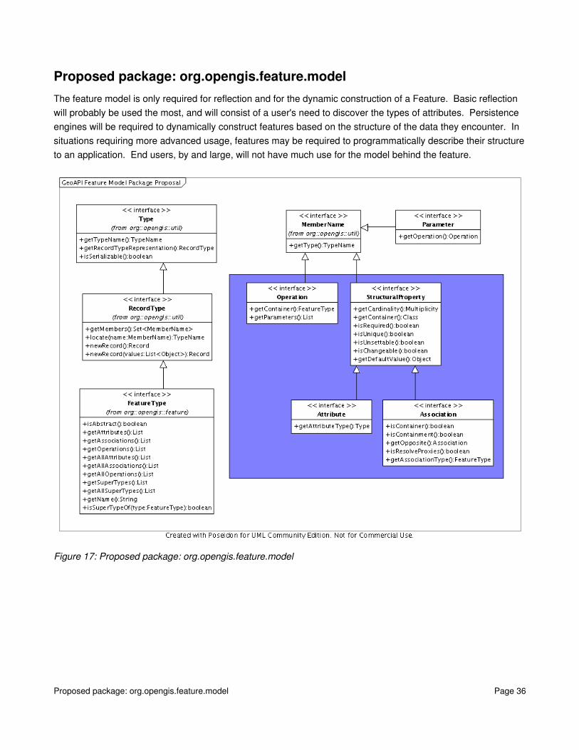
Proposed package: org.opengis.feature.modelThe feature model is only required for reflection and for the dynamic construction of a Feature. Basic reflection will probably be used the most, and will consist of a user's need to discover the types of attributes. Persistence engines will be required to dynamically construct features based on the structure of the data they encounter. In situations requiring more advanced usage, features may be required to programmatically describe their structure to an application. End users, by and large, will not have much use for the model behind the feature.
Figure 17: Proposed package: org.opengis.feature.model
Proposed package: org.opengis.feature.model Page 36
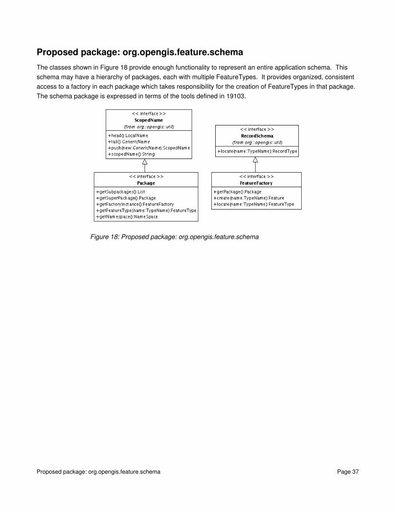
Proposed package: org.opengis.feature.schemaThe classes shown in Figure 18 provide enough functionality to represent an entire application schema. This schema may have a hierarchy of packages, each with multiple FeatureTypes. It provides organized, consistent access to a factory in each package which takes responsibility for the creation of FeatureTypes in that package. The schema package is expressed in terms of the tools defined in 19103.
Figure 18: Proposed package: org.opengis.feature.schema
Proposed package: org.opengis.feature.schema Page 37
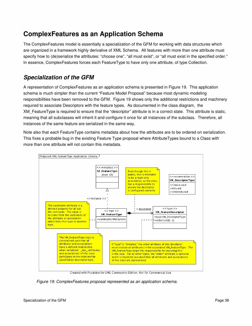
ComplexFeatures as an Application SchemaThe ComplexFeatures model is essentially a specialization of the GFM for working with data structures which are organized in a framework highly derivative of XML Schema. All features with more than one attribute must specify how to (de)serialize the attributes: “choose one”, “all must exist”, or “all must exist in the specified order.” In essence, ComplexFeatures forces each FeatureType to have only one attribute, of type Collection.
Specialization of the GFMA representation of ComplexFeatures as an application schema is presented in Figure 19. This application schema is much simpler than the current “Feature Model Proposal” because most dynamic modeling responsibilities have been removed to the GFM. Figure 19 shows only the additional restrictions and machinery required to associate Descriptors with the feature types. As documented in the class diagram, the XM_FeatureType is required to ensure that the “descriptor” attribute is in a correct state. This attribute is static, meaning that all subclasses will inherit it and configure it once for all instances of the subclass. Therefore, all instances of the same feature are serialized in the same way.
Note also that each FeatureType contains metadata about how the attributes are to be ordered on serialization. This fixes a probable bug in the existing Feature Type proposal where AttributeTypes bound to a Class with more than one attribute will not contain this metadata.
Figure 19: ComplexFeatures proposal represented as an application schema.
Specialization of the GFM Page 38

Proposed package: org.opengis.appschema.xmlWhether the need to specify attribute ordering is common enough to merit inclusion in a multiplatform interface library is a question I do not have enough information to answer. However, I have been told that this capability is key to the operation of Filter classes. It also provides a way for features deserialized from XML to retain enough information to reserialize them back to XML. An alternative to Figure 19 which would also accomplish this goal is to associate a complete XML Schema with the root Feature deserialized from the XML file.
Assuming that Figure 19 is both necessary and correct, Figure 20 represents a proposed representation as GeoAPI interfaces. The three green boxes in Figure 20 separate the definition of the Descriptors from the definition of the XMLFeatures, from the definition of XMLFeatureTypes.
It should be made clear that the implementors of the XMLFeatureType interface bear all responsibility for ensuring that the attributes and associations exposed via the org.opengis.feature reflection API are synchronized with the specialized XML Schema representation. However, this functionality is a good candidate for centralization in a single implementation class which is extended at will.
Figure 20: Proposed package: org.opengis.appschema.xml
Proposed package: org.opengis.appschema.xml Page 39


