Page 1
1 Copyright © 2013 by ASME
Proceedings of the ASME 2013 International Design Engineering Technical Conferences & Computers and Information in Engineering Conference
IDETC/CIE 2013 August 4-7, 2013, Portland, Oregon, USA
DETC2013-13132
AN MRI COIL-MOUNTED MULTI-PROBE ROBOTIC POSITIONER FOR CRYOABLATION
Faye Y. Wu Mechanical Engineering Department
Massachusetts Institute of Technology Cambridge, MA, USA
Meysam Torabi Wyss Institute for Biologically Inspired Engineering
School of Engineering and Applied Sciences Harvard University
Cambridge, MA, USA
Atsushi Yamada Department of Radiology
Brigham and Women’s Hospital Boston, MA, USA
Alex Golden School of Engineering and
Applied Sciences Harvard University
Cambridge, MA, USA
Gregory S. Fischer Mechanical Engineering
Department Worcester Polytechnic Institute
Worcester, MA, USA
Kemal Tuncali, M.D. Department of Radiology
Brigham and Women’s Hospital Boston, MA, USA
Dan D. Frey Mechanical Engineering
Department Massachusetts Institute of
Technology Cambridge, MA, USA
Conor Walsh Wyss Institute for Biologically
Inspired Engineering
School of Engineering and Applied Sciences Harvard University
Cambridge, MA, USA
ABSTRACT Cryoablation is a percutaneous procedure for treating
solid tumors using needle-like instruments. This paper presents
an interventional guidance device for faster and more accurate
alignment and insertion of multiple probes during cryoablation
performed in closed bore magnetic resonance (MR) imaging
systems. The device is compact and is intended to be mounted
onto a Siemens 110 mm MR loop coil. A cable-driven two-
degrees-of-freedom spherical mechanism mimics the wrist
motion as it orients the intervention probes about a remote
center of motion located 15 mm above the skin. A carriage
interfaces with the probes via a thumbscrew-fastened latch to
passively release the probes from their tracks, enabling them to
be inserted sequentially and freeing them to move with
respiration. Small actuator modules containing piezoelectric
encoder-based motors are designed to be snap-fit into the
device for ease of replacement and sterilization. The robot MRI
compatibility was validated with standard cryoablation
imaging sequences in 3T MR environment, yielding a maximum
of 4% signal to noise ratio during actuator motion. Bench-level
device characterization demonstrated a maximum error of
0.78° in the carriage movement. Needle-tip placement
experiments for multiple targets in gelatin were performed
using our image-guided navigation software, measuring an
average targeting error of 2.0 mm.
INTRODUCTION Cryoablation, a minimally invasive procedure, treats soft
tissue cancer found in the lung, liver, breast, kidney and prostate
through the precise placement of liquid nitrogen or pressurized
argon gas filled probes [1]. Recent interventional cryoablation
studies reported almost 100% efficacy for the treatment of small
renal tumors (≤4 cm) [2, 3]. This method is less painful, has
lower risk of developing metastatic disease and requires fewer
retreatments than radiofrequency ablation [4-6].
Page 2
2 Copyright © 2013 by ASME
Cryoablation is often performed in conjunction with
Magnetic Resonance Imaging (MRI) to track the position of
ablation probes, as well as to visualize the ice ball formation for
direct comparison between the kill zone and the tumor margin.
After interventionists determine the location of a lesion with an
initial scan, they would approximate an entry site for the probe
on the surface of the skin and make a small incision at the entry
site to facilitate insertion. The imaging data is used to estimate
the desired compound entry angle and the probe is inserted in
an iterative manner, a few centimeters at a time, each time
checking its trajectory with MR scans, until the tip reaches the
desired endpoint inside the patient. Given the limited space
within an MRI machine, the manual insertion and adjustment of
the intervention probe must be conducted outside the imaging
bore. The interventionist must compromise between efficiency
and precision, as each scan and adjustment necessitates sliding
the patient into and out of the bore. Additionally, the
simultaneous use of multiple probes is usually needed to create
a synergistic ice formation that encompasses the entire tumor
and ensure the tumor reaches the minimal required ablation
temperature of -40°C [7-9]. Due to the challenges in precisely
calculating the desired entry angle and subsequently inserting
the needle along it, more than half of the procedure time may be
spent correcting probe path [10]. Similarly, inserting the probe
precisely along its planned path was also observed to be the
most time-intensive portion of the operation for many CT-
guided interventions [11].
To solve the probe alignment challenge, a number of
devices have been developed in recent years. Taillant et al. [12]
and Hata et al. [13] introduced MRI compatible systems that
mount on the scanner bed and suspend over the patient. The
breast biopsy and intervention apparatus presented by Larson et
al. [14] uses telescopic rods to situate probes while keeping
ultrasonic actuators away from the imaging bore to minimize
any distortion effects to the MR images. Kokes et al. [15]
reported another MRI compatible needle driver for breast tumor
radiofrequency ablation, which employs a haptic device to
remotely control the robot. Rasmus et al. [16], Muntener et al.
[17] and Su et al. [18] developed bed-mounting robotic
mechanisms that targeted single probe treatment of the prostate
gland. Walsh et al. [19] designed a compact device that attaches
directly to the patient via adhesive pads and orients a single
probe for CT and ultrasound-image-guided biopsy.
The available technologies for placing probes are either
large plus expensive or designed to work with single probe
ablation only. Furthermore, unique to MR-image-guided
procedures, a flexible imaging coil must be affixed to the
patient over the region of interest to capture radio frequency
data coming from the body and produce high quality images.
Many mechanisms designed for CT or ultrasound-image-guided
procedures cannot accommodate imaging coil placements,
limiting their possibilities of redesigning for MR-guided
operations.
Therefore, there is a clear opportunity for an inexpensive,
small footprint MRI-compatible system that mounts directly to
the imaging coil and enables rapid, precise and accurate
guidance for multiple probes. This paper presents the design
and evaluation of such a system. The device is designed
primarily for cryoablation performed in the abdominal area,
where multiple probes are required, but it can also be used for
other image-guided percutaneous instrument insertions.
DEVICE DESIGN The robot presented in this paper is designed to work for
the most common clinical case, where three 17-gauge probes
(1.473 mm in diameter and 17.5 cm long) are placed, sharing
the approximate same probe insertion site on the skin, to reach
an average depth of 125 mm and maximum tilt of ±45°.
Typically, the tumor is 25-30 mm in diameter.
Mechanism Design Concept
The form factor of the device was greatly influenced by the
procedure work-flow and the ease of sterilization. It was
determined that a total of three degrees of freedom (DOFs) are
essential in the placement of multiple intervention probes: two
actuated DOFs for orienting the probe and one passive DOF for
releasing the probe from a guide after insertion. The action of
inserting the probe was decided to be performed manually to
ensure safety of the patient. Utilizing the device and
corresponding navigation software to set the angle of insertion,
the interventionist can accurately position the probes without
performing multiple scans. To optimally utilize the small
workspace inside a closed bore, a coil-mounted system that
places up to three cryoablation probes was designed as shown
in Fig. 1.
Figure 1. THE DEVICE CONTAINS TWO ACTUATED DOFS FOR ORIENTING THE PROBE AND ONE MANUALLY
CONTROLLED DOF FOR RELEASING THE PROBE. THE HOLLOW ROUND BASE ENABLES THE DEVICE TO BE MOUNTED TO AN IMAGING COIL AND ALLOWS THE
PHYSICIAN TO HAVE ACCESS TO THE INSERTION SITE.
Typically, the device and the enclosed imaging coil are
mounted on the patient with straps or adhesive pads. The probes
are placed one at a time, as shown in Fig. 2. The arc and
Page 3
3 Copyright © 2013 by ASME
carriage move to the first position, allowing the probe inside the
first track to be inserted manually. The probe can then be
released simply by opening the clamping mechanism and
actuating the arc to the next position to guide the newly placed
probe in the second track. The arc should always rotate in the
same direction to avoid colliding with previously placed probes,
and the software driving the device assists the user with
managing the order of probe placement. Key design features are
addressed below and more details can be found in [20].
Figure 2. PROBES ARE PLACED SEQUENTIALLY AND LEFT IN PLACE.
Spherical Mechanism
Mimicking the wrist motion, a spherical mechanism
consisting of an arc and a carriage was chosen to describe the
two angular DOFs of the probe. The two components’ axes of
rotation are coplanar; their intersection point is the RCM and is
positioned as close as possible to the preselected probe
insertion point, which in the current prototype is 15 mm above
the skin surface due to actuator size, to minimize the length of
the entry site incision.
The motion of the carriage is constrained by a custom-
designed roller bearing. Since a small misalignment between the
carriage and arc would amplify error at the probe tip, the
appropriate bearing stiffness was designed and tested not only
to enable smooth, low friction motion, but also to decrease
backlash and other undesired movement. As shown in Fig. 3,
the arc profile is trapezoidal. Five rollers, four on the top and
one on the bottom, are preloaded onto the sides of the arc. The
walls of the carriage are offset from the surface of the arc by 1.5
mm, avoiding sliding friction caused by direct contact.
Figure 3. THREE TRACKS ON THE CARRIAGE SEPARATE THE PROBES TO PREVENT THEM FROM INTERSECTING AT RCM. A THUMBSCREW AND LATCH COMBINATION IS USED TO PRELOAD AND LOCK THE PROBES IN THE CARRIAGE. THE CUSTOM-DESIGNED ROLLER BEARING CONSTRAINS
THE MOTION OF THE CARRIAGE AND MINIMIZES FRICTION.
Hertz contact stress between the roller and the surface of
the arc was calculated to prevent significant pitting or fatigue at
the contact surfaces. Small and wide rubber rollers were
selected to increase the contact area, decrease maximum contact
stress on the rollers, and improve traction. The outer diameter
of the roller is three times the diameter of the dowel pin holding
it in the carriage, allowing the roller to rotate easily on the pin
without losing excess energy from its sliding contact with the
pin [21]. This is important in reducing the torque and power
requirements of the actuators. Bench level experiment
conducted with a Logger Pro force sensor (Vernier Software
and Technology, Beaverton, OR) showed that a maximum force
of 2.71 N, with a standard deviation of 0.01 N, is required to
move the carriage along the arc.
The probes are secured to the carriage from the side,
allowing them to be easily disengaged from the carriage as the
arc rotates clockwise about the x-axis. A thumb screw fastens a
door-like latch on the carriage, locking the probes in place with
friction and compression. As mentioned earlier, the three needle
tracks, spaced 3 mm apart, prevent the probes from intersecting
at the RCM while maintaining the 2-DOF spherical movement.
The tracks are tilted 14° to direct the probes toward the x-axis,
as illustrated in Fig. 3.
Actuation and Cable Based Transmission
Piezo LEGS rotatory motors (Piezomotor, Sweden) were
selected for this device due to the small size, large torque
capacity, low image distortion, low friction and ease of position
control compared to other MRI compatible actuators, such as
Shinsei ultrasonic motor [22], pneumatics [23] and hydraulics
[24]. Encoder modules were obtained (US Digital, Vancouver,
WA) to perform closed loop control.
Actuators and the associated electronics are difficult to
clean with conventional sterilization processes, thus they were
designed to be enclosed in a single removable casing that snaps
into the remainder of the device (Fig. 4). The square end of the
extension shaft, along with the peg-in-hole feature in the casing,
Figure 4. REPLACEABLE MOTOR MODULES ENCLOSE ELECTRONICS THAT ARE DIFFICULT TO STERILIZE AND
SNAP-FIT INTO THE BASE.
Page 4
4 Copyright © 2013 by ASME
facilitates the snap-fit attachment of actuation module.
The amount of noise introduced to the MR image is
minimized when the motors are placed on the side of the robot.
Thus for the moving carriage, a cable-driven system is required
to remotely transmit motion from the motor. Dyneema plastic
cable was selected for this application as it is MRI compatible,
and has high strength, low stretch, and high lubricity [25]. The
cable makes a closed loop: it begins from a driving pulley,
attaches to two sides of the carriage, wraps around a tensioning
pulley, and comes back to the driving pulley. Figure 5 shows the
main forces acting on the cable-driven system. Estimating the
friction between the cable and the arc with the Capstan
principle, the maximum torque required to move the carriage is
0.02 Nm, which is well within the limit of the Piezo LEGS
rotatory motors.
Figure 5. FREE BODY DIAGRAM OF THE CABLE-DRIVEN SYSTEM.
Figure 6 demonstrates the design of the arc. It contains a
pocket for a double layered driving pulley that isolates the
outgoing and returning cables to minimize friction. The arc and
the driving pulley each contain a square hole to interface with
the extension shaft in the motor module. The bottom of the arc
snap-fits into corresponding features on the fixed base and
provides rotational alignment. The bolt-driven u-shaped
tensioning mechanism shown in Fig. 7 is designed to eliminate
backlash and improve stiffness of the carriage as it travels along
the arc.
Figure 6. DIMENSION OF THE ARC IS DRIVEN BY THE SIZE OF THE IMAGING COIL AND THE TRAVEL RANGE OF THE
CARRIAGE.
Figure 7. THE CABLE TENSIONING MECHANISM USES A BOLT TO FINE TUNE THE POSITION OF THE TENSIONING
PULLEY AND ELIMINATE BACKLASH.
Base Design
The base of the device is designed to specifically cover the
110 mm Siemens 4-channel Flex Loop Interface (Siemens,
Germany), as shown in Fig. 1. The large round window, in
addition to placing the arc 45° off the major axis of the base,
allows interventionists to easily access the center of the base
from either side of the arc and perform tasks such as making the
probe entry site incision and manually adjusting the probe after
it has been released.
The inner wall of the base contains three layers. Six 6 mm
spherical pinpoint fiducials from Beekly (Bristol, CT) are
sandwiched between the layers to serve as registration markers.
The distance between any two fiducial capsules is unique,
enabling a registration algorithm to quickly identify the
orientation and location of the device in the image coordinate
system.
Static finite element analysis (FEA) was carried out using
SimulationXpress 2010 (SolidWorks Corp., Santa Monica, CA)
to ensure structural integrity during probe orientation and
insertion. Each component was analyzed separately based on
forces and boundary conditions derived from first order
approximation, with a worst case scenario of 10 N probe
insertion force [19]. The results showed that the 3D printed
plastic components are able to withstand the necessary
interaction forces and would exhibit negligible or, in the case of
snap-fit features, acceptable deformation.
System Kinematics
A straightforward closed-form inverse kinematics for the
system can be formulated as follows:
1
1tan
yq
z
− =
,
1
2sin
xq
r
− − =
, 2 2 2r x y z= + + (1)
where q1 and q2 are angles of arc and carriage respectively, and
r is the insertion length needed to reach the given target located
at (x, y, z) from the RCM, as illustrated in Fig. 8.
Page 5
5 Copyright © 2013 by ASME
Figure 8. A SIMPLE MODEL USED TO REPRESENT THE DEVICE COORDINATE SYSTEM. THE SEMICIRCLE IS THE ARC, THE SQUARE IS THE CARRIAGE, THE DOT IS THE
TARGET, AND THE SOLID LINE IS THE PROBE.
For the kinematics of the actual mechanism, 14° needs to
be added to q1 due to the tilt of the needle tracks, and for q2, a
compensation angle is needed for probes placed in different
tracks. Demonstrated in Fig. 9a, if a probe in track 2 (left dotted
line) coincides with the target, then the probe in track 3 (right
dotted line) needs to rotate clockwise by δq2 to reach the target
(lower solid line). Similarly, a probe in track 1 needs to rotate
counterclockwise by δq2 to reach the target (Fig. 9b). It can also
be seen that by separating the probes into different tracks, they
do not intersect at the origin (RCM). Here, track 1 is defined as
the left most track, track 3 as the right most track, and track 2 as
the middle track, which also intersects the RCM.
Figure 9. ANGLE COMPENSATION IS NEEDED FOR PROBES PLACED IN TRACKS OTHER THAN THE ONE IN THE
MIDDLE (TRACK 2).
The compensation angle can be found from
1
2tan
dq
rδ
− =
(2)
where d is the distance between the needle tracks (3 mm).
Taking into account the ratio between the radius of the driving
pulley and the radius of the arc, as well as change in the
absolute position of the cable as the arc moves, the amount of
motor rotation needed to drive the carriage can be determined.
The inverse kinematics relating the target coordinates to the
motor angles are
1
1tan 14
m
yq
z
− = +
(3)
2 2 2 1 1[ ( 2) ] 'arc
m
pulley
rq q track q q q
rδ= + − − − (4)
where rarc is 80 mm, rpulley is 7 mm, and |q1'-q1| is the change of
arc position.
A MATLAB script with graphical output (Fig. 10) was
written to simulate the operation of the device and verify the
above kinematics equations. Targets can either be generated or
defined by the user based on known physical conditions of
cryoablation. A simple sorting function reorders the target
points to maintain clockwise arc rotation and prevent the arc
from colliding with previously placed probes. The inverse
kinematics is adjusted to allow the probe in track 1 to reach the
first target, probe in track 2 to reach the second target, and so
forth. The minimum distances between the probes are calculated
to ensure that the probes do not intersect with one another.
Figure. 10. THE MATLAB SCRIPT SIMULATES DEVICE OPERATION AND VERIFIES KINEMATICS. THE MINIMUM
DISTANCES BETWEEN THE PROBES ARE CALCULATED TO ENSURE THEY DO NOT INTERSECT AT THE RCM.
PROTOTYPING AND CONTROL IMPLEMENTATION The device was 3D printed with ABS (Objet Ltd., Rehovot,
Israel) with a view that it could be manufactured at a larger
scale using injection molding. Figure 11 shows the prototype
with three probes clamped in the needle guide.
Page 6
6 Copyright © 2013 by ASME
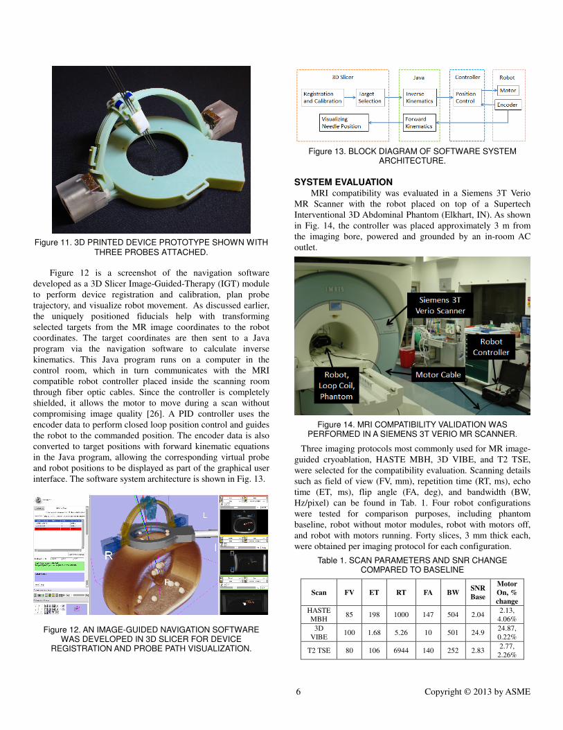
Figure 11. 3D PRINTED DEVICE PROTOTYPE SHOWN WITH THREE PROBES ATTACHED.
Figure 12 is a screenshot of the navigation software
developed as a 3D Slicer Image-Guided-Therapy (IGT) module
to perform device registration and calibration, plan probe
trajectory, and visualize robot movement. As discussed earlier,
the uniquely positioned fiducials help with transforming
selected targets from the MR image coordinates to the robot
coordinates. The target coordinates are then sent to a Java
program via the navigation software to calculate inverse
kinematics. This Java program runs on a computer in the
control room, which in turn communicates with the MRI
compatible robot controller placed inside the scanning room
through fiber optic cables. Since the controller is completely
shielded, it allows the motor to move during a scan without
compromising image quality [26]. A PID controller uses the
encoder data to perform closed loop position control and guides
the robot to the commanded position. The encoder data is also
converted to target positions with forward kinematic equations
in the Java program, allowing the corresponding virtual probe
and robot positions to be displayed as part of the graphical user
interface. The software system architecture is shown in Fig. 13.
Figure 12. AN IMAGE-GUIDED NAVIGATION SOFTWARE WAS DEVELOPED IN 3D SLICER FOR DEVICE
REGISTRATION AND PROBE PATH VISUALIZATION.
Figure 13. BLOCK DIAGRAM OF SOFTWARE SYSTEM
ARCHITECTURE.
SYSTEM EVALUATION MRI compatibility was evaluated in a Siemens 3T Verio
MR Scanner with the robot placed on top of a Supertech
Interventional 3D Abdominal Phantom (Elkhart, IN). As shown
in Fig. 14, the controller was placed approximately 3 m from
the imaging bore, powered and grounded by an in-room AC
outlet.
Figure 14. MRI COMPATIBILITY VALIDATION WAS PERFORMED IN A SIEMENS 3T VERIO MR SCANNER.
Three imaging protocols most commonly used for MR image-
guided cryoablation, HASTE MBH, 3D VIBE, and T2 TSE,
were selected for the compatibility evaluation. Scanning details
such as field of view (FV, mm), repetition time (RT, ms), echo
time (ET, ms), flip angle (FA, deg), and bandwidth (BW,
Hz/pixel) can be found in Tab. 1. Four robot configurations
were tested for comparison purposes, including phantom
baseline, robot without motor modules, robot with motors off,
and robot with motors running. Forty slices, 3 mm thick each,
were obtained per imaging protocol for each configuration.
Table 1. SCAN PARAMETERS AND SNR CHANGE COMPARED TO BASELINE
Scan FV ET RT FA BW SNR
Base
Motor
On, %
change
HASTE
MBH 85 198 1000 147 504 2.04
2.13,
4.06%
3D
VIBE 100 1.68 5.26 10 501 24.9
24.87,
0.22%
T2 TSE 80 106 6944 140 252 2.83 2.77,
2.26%
Page 7
7 Copyright © 2013 by ASME
Figure 15 illustrates the MR images obtained from baseline
and during motor operation. The pixel difference between the
two images shows small amount of identifiable noise and
distortion inside the phantom. The signal to noise ratio (SNR)
was calculated as the mean pixel intensity in the center of the
phantom divided by the noise intensity (root mean square signal
intensity) outside the phantom. As can be observed in Tab. 2,
the maximum change in normalized SNR for motor running
condition is 4.06% compared to the baseline. This is sufficiently
small to not interfere with the operation. MRI compatibility
tests conducted with similar controller and actuators can be also
found in [27], which reported comparable change in SNR
(2.1%).
Figure 15. SUBTRACTION NOISE ANALYSIS SHOWS SMALL AMOUNT OF PIXEL DIFFERENCE BETWEEN BASELINE AND
MOTOR RUNNING CONDITIONS.
Figure 16 depicts the bench level test setup with a 6-DOF
electromagnetic (EM) tracker system (Ascension Tech, Milton,
VT) to evaluate the angular accuracy of the arc and the carriage.
Figure 16. EXPERIMENTAL SETUP WITH A 6-DOF EM TRACKER SYSTEM TO EVALUATE BENCH LEVEL DEVICE
PERFORMANCE
The system’s repeatability was measured by moving the arc
and the carriage independently to a commanded position
approaching from either direction. Figure 17 represents bi-
directional performance over six trials for each commanded
position: three in the forward direction and three in the reverse
direction. The extreme angles (±45°) can only be approached
from one direction; hence only three values are available. The
mean of the data corresponds to the accuracy of the system.
Figure 17. DEVICE PERFORMANCE MEASURED WITH EM TRACKER SYSTEM. THE TOP PLOT IS THE ARC ERROR
AND THE BOTTOM PLOT IS THE CARRIAGE ERROR.
Table 2 summarizes the test results. The arc shows
consistent behavior as it moves in both directions. The
maximum arc error is found to be -0.65°. The slightly larger arc
error in the reverse direction, which may be caused by the
asymmetrical shape and load of the carriage, would not affect
targeting accuracy since only forward movement (clockwise
about x-axis) is required during probe placement. The carriage
exhibited more overall error, with a maximum of 0.78°.
Tensioning the cable prior to the test may improve the carriage
performance. With an average probe insertion depth of 125 mm,
the angular errors translate to a probe tip error of 2.2 mm.
Table 2. BENCH-LEVEL DEVICE CHARACTERIZATION
Forward Backward
Arc (q1) -0.02°±0.17° -0.02°±0.25°
Carriage (q2) 0.43°±0.18° -0.41°±0.17°
Finally, targeting accuracy of the device was evaluated in
gelatin to simulate probe placement in tissue. To register the
coordinate system of the EM tracker to the coordinate system of
the robot, two EM sensors were secured to the base of the
device, as shown in Fig. 18. An additional EM sensor was
Page 8
8 Copyright © 2013 by ASME
installed on the tip of the needle to track its movement within
the gelatin. The needle used for the targeting test was a hollow
Nitinol tube, which is compatible with the EM field. Figure 19
shows the results of a test in gelatin with 8 targets shaping a
“folded star.” The targets were reached using all three needle
tracks. The dotted and solid lines show the desired and actual
patterns respectively while the maximum error never exceeded
5 mm. The measured targeting errors, 2.0 mm ± 1.5 mm, are
larger than the previously calculated 2.2 mm, which may be
caused by insertion depth error and needle’s bending in gelatin.
A CT-compatible spherical mechanism for positioning a single
probe also reported similar results (2.3 mm ± 1.3 mm) [28].
Figure 18. EXPERIMENTAL SETUP WITH 6-DOF EM SENSORS TO REGISTER THE COORDINATE SYSTEMS AND
TRACK THE NEEDLE’S TIP IN GELATIN.
Figure 19. TARGETING RESULTS FROM EXPERIMENTS PERFORMED IN GELATIN (GRID SHOWN IN CM INTERVAL). THE PLANNED PATTERN IS SHOWN WITH DOTTED LINES, AND THE ACTUAL PATTERN IS SHOWN WITH SOLID LINES.
ERROR VARIES FROM 0.9 MM TO 4.5MM FOR THE 8 TARGETS.
CONCLUSION AND FUTURE WORK The 3D printed prototype is a proof of concept for
positioning multiple probes for MR-image-guided percutaneous
interventions. Such a novel device offers a practical and cost-
effective approach to improving the placement of multiple
ablation probes to match a treatment plan. The device becomes
part of the procedural work-flow as it is mounted together with
the MR image coil on the patient. The two actuators are
integrated into reusable modules that snap into a single-use or
sterilizable base to help maintain a sterile field.
Future work includes verifying the reliability of each
component and optimizing the design. Shielding the actuator
modules will further reduce change in SNR. Probe insertion
experiments in a phantom model inside an MRI machine are
planned and will yield additional useful information for
improving the cryoablation work-flow when a robotic positioner
is used. Tests need to be performed to guarantee safety before
an automated insertion mechanism or steerable ablation probe
can be incorporated to further simplify probe positioning and
account for probe deflection in tissue. Ultimately, this robot is
envisioned to perform automatic probe placement and ablation
inside any medical imaging machine, enabling faster, safer, and
more economical interventions.
ACKNOWLEDGMENTS This work is funded by the Partners Radiology Research
Award and the Wyss Institute for Biologically Inspired
Engineering. We would like to thank the Singapore Ministry of
Education through the collaboration between MIT and the
Singapore University of Technology and Design. Also, thanks
to Greg Cole, Kevin Harrington, and Hao Su from the
Automation and Interventional Medicine Lab at WPI for the
assistance in learning how to use the motor controller.
REFERENCES [1] Gage, A.A., 1998, "History of cryosurgery," Semin Surg
Oncol., 14, pp. 99 -109.
[2] Lindsey, H, 2007, "Percutaneous Cryoablation Effective for
Select Patients with Kidney Tumors," Oncology Times, 29
(11), pp. 35-36.
[3] Georgiades, C.S., Hong, K., Bizzell, .C, Geschwind, J.F.,
Rodriguez, R., 2008, "Safety and Efficacy of CT Guided
Percutaneous Cryoablation for Renal Cell Carcinoma,"
JVIR, 9, pp. 1302-1310.
[4] Allaf, M.E., Varkarakis, I.M., Bhayani, S.B., Inagaki, T.,
Kavoussi, L.R., Solomon, S.B., 2005, "Pain control
requirements for percutaneous ablation of renal tumors:
cryoablation versus radiofrequency ablation—initial
observations," Radiology, 237(1), pp. 366–370.
[5] Kunkle, D.A., Uzzo, R.G., 2008, "Cryoablation or
radiofrequency ablation of the small renal mass: a meta-
analysis," Cancer, 113(10), pp. 2671–2680.
[6] Hegarty, N.J., Gill, I.S.,Desai, M.M., Remer, E.M.,
O'Malley, C.M., Kaouk, J.H., 2006, "Probe-ablative
nephron-sparing surgery: cryoablation versus
radiofrequency ablation," J Urol, 68(1 suppl), pp. 7–13.
[7] Permpongkosol, S., Nicol, T.L., Khurana, H., et al., 2007,
"Thermal maps around two adjacent cryoprobes creating
overlapping ablations in porcine liver, lung, and kidney," J
Vasc Interv Radiol, 18(2), pp. 283–287.
[8] Weld, K.J., Hruby, G., Humphrey, P.A., Ames, C.D.,
Landman, J., 2006, "Precise characterization of renal
parenchymal response to single and multiple cryoablation
probes," J Urol, 176(2), pp. 784–786.
Page 9
9 Copyright © 2013 by ASME
[9] Chosy, S.G., Nakada, S.Y., Lee, F.T. Jr., Warner, T.F., 1998,
"Monitoring renal cryosurgery: predictors of tissue necrosis
in swine," J Urol, 159(4), pp. 1370–1374.
[10] Deisenhofer, I., et al., 2010, "Cryoablation versus
radiofrequency energy for the ablation of atrioventricular
nodal reentrant tachycardia (the CYRANO Study): results
from a large multicenter prospective randomized trial,"
Circulation, 122(22), pp. 2239-45.
[11] Walsh, c., Sapkota, B., Kalra, M., Hanumara, N., Liu, B.,
Shepard, J., Gupta, R., 2011, “Smaller and Deeper Lesions
Increase Radiation Dose and Time in during Trajectroy
Planning and Needle Insertion in CT-Guided Lung Biopsy,”
J. Thorac Imaging, 26(3), pp. 196-203.
[12] Taillant, N., Avila-Vilchis, J.C., Allegrini, I.B., Cinquin, P.,
2004, “CT and MR compatible light puncture robot:
architectural design and first experiments,” Proc. 2004 Int’l
Soc.& Conf. Series on Med Image Computing and
Computer-Assisted Intervention, Vol. 2, pp. 145–154.
[13] Hata, N., Tokuda, J., Hurwitz, S., Morikawa, S., 2005,
“Needle Guiding Robot for MR-guided Microwave
Thermotherapy of Liver Tumor using Motorized Remote-
Center-of-Motion Constraint in Robotics and Automation,”
Proc. 2005 IEEE Int’l Conf. Automation and Robotics,
Barcelona.
[14] Larson, B.T., Erdman, A.G., Tsekos, N.V., Yacoub, E.,
Tsekos, P.V., Koutlas, I.G., 2004, “Design of an MRI-
Compatible Robotic Stereotactic Device for Minimally
Invasive Interventions in the Breast,” J. Biomech. Engr,
126(4), pp. 458-465.
[15] Kokes, R., Lister, K., Gullapalli, R., Zhang, B., MacMillan,
A., Richard, H., Desai, J., 2009, “Towards a teleoperated
needle driver robot with haptic feedback for RFA of breast
tumors under continuous MRI,” Med. Image Anal., 13(3),
pp. 445 – 55.
[16] Rasmus, M., Dziergwa, S., Haas, T., Madoerin, P., Huegli,
R., Bilecen, D., Jacob, A.L., 2007, “Preliminary clinical
results with the MRI-compatible guiding system
INNOMOTION,” Int J CARS, 2, pp. 138 -145.
[17] Muntener, M., Patriciu, A., Petrisor, D., Mazilu, D., Bagga,
H., Kavoussi, L., Cleary, K., Stoianovici, D., 2006,
“Magnetic Resonance Imaging compatible robotic system
for fully automated brachytherapy seed placement,” J Urol,
68(6), pp. 1313–1317.
[18] Su, H., Camilo, A., Cole, G.A., Hata, N., Tempany, C.M.,
Fischer, G.S., 2011, “High-field MRI-compatible needle
placement robot for prostate interventions,” Stud Health
Technol Inform, 163, pp. 623-629.
[19] Walsh, C., Hanumara, N., Slocum, A., Shepard, J., Gupta,
R., 2008, “A patient-mounted telerobotic tool for CT-
guided percutaneous interventions,” ASME Journal of
Medical Devices, 2(1).
[20] Wu, F., 2013, "Multi-probe robotic positioner for
cryoablation in MRI," SMME Thesis, MIT, Cambridge,
MA, USA.
[21] Slocum, A.H., 1992, Precision Machine Design, Society of
Manufacturing.
[22] Fischer, G.S., Krieger, A., Iordachit, I., Csoma, C.,
Whitcomb, L., Fichtinger, G.., 2008, “MRI Compatibility
of Robot Actuation Techniques – A Comparative Study,”
MICCAI 2008, Part II, LNCS 5242, pp. 509–517.
[23] Wang, Y., Shazeeb, M.S., Sotak, C.H., Fischer, C.S., 2009,
“Optimization of Piezoelectric Motors to Enhance MR
Compatibility for Interventional Devices,” 17th Sci.
Meeting and Exhibition of the Int’l Soci. of Mag. Reso. in
Med. - ISMRM 2009.
[24] Verdirame, J., 2000, "Characterization of a Hydraulic
Actuator for a Functional Magnetic Resonance Imaging
Robot," BSME Thesis, MIT, Cambridge, MA, USA.
[25] Stein, H. L., 1998, “Ultrahigh molecular weight
polyethylenes (uhmwpe),” Engineered Materials
Handbook, 2, 167–171.
[26] Cole, G.., Harrington, K., Su, H., Camilo, A., Pilitsis, J.,
Fischer, G.S., 2010, “Closed-Loop Actuated Surgical
System Utilizing Real-Time In-Situ MRI Guidance,” 12th
Int’l Symp. on Expe. Robotics - ISER 2010
[27] Wang, Y., Cole, G.A., Su, H., Pilitis, J.G., Fischer, G.S.,
2009, “MRI Compatibility Evaluation of a Piezoelectric
Actuator System for a Neural Interventional Robot,” 31st
Annual Int’l Conf. of the IEEE Engr. Med. and Bio. Soci. -
EMBC 2009, Minneapolis, MI.
[28] Maier-Hein, L., Walsh, C., Seitel, A., Hanumara, N.,
Shepard, J., Pianka, F., Muller, B., Slocum, A., Gupta, R.,
Meinzer, H-P., 2009, “Human vs. Robot Operator Error in
a Needle-Based Navigation System for Percutaneous Liver
Intervention,” Proc. SPIE, vol. 7261, pp. 72610Y-72610Y-
12.