30
© Copyright 2015 NCC Group An NCC Group Publication Porting the Misfortune Cookie Exploit: A Look into Router Exploitation Using the TD-8817 Prepared by: Grant Willcox
© Copyright 2015 NCC Group
An NCC Group Publication
Porting the Misfortune Cookie Exploit: A Look
into Router Exploitation Using the TD-8817 Prepared by:
Grant Willcox

© Copyright 2015 NCC Group
Contents 1 Summary ........................................................................................................................................................ 3 2 Background .................................................................................................................................................... 3 3 Equipment ...................................................................................................................................................... 4 4 Confirming the Bug Exists .............................................................................................................................. 4 5 Analysing the Firmware ................................................................................................................................. 5 6 The CPU Problem .......................................................................................................................................... 7 7 Opening the Case ........................................................................................................................................ 18
7.1 Identifying Pin Purpose ....................................................................................................................... 21 7.2 Connecting the USB Adapter to the Pins ........................................................................................... 21
8 Identifying the Baud rate with /dev/ttys0’s Baudrate.py Tool ....................................................................... 22 9 Connecting Into the Router with Minicom .................................................................................................... 24 10 Triggering the Crash with Router Debugging Output .................................................................................. 25 11 Running Test Cases to Identify the Algorithm Used .................................................................................... 27
11.1 Calculating the Correct Address from Test Cases ............................................................................. 28 12 Testing the Address ..................................................................................................................................... 28 13 Conclusion ................................................................................................................................................... 30
© Copyright 2015 NCC Group
1 Summary
By using just a few commonly available tools and a bit of time, it is possible to port the Misfortune Cookie exploit to exploit a TD-8817 V8 router running the latest firmware and gain reliable control over its web interface without crashing the router, even after repeated exploitation attempts.
In this whitepaper, I will discuss how I went about disassembling and debugging a TD-8817 v8 router to develop a compatible Misfortune Cookie exploit, which would allow me to gain reliable access to the admin control panel on the web interface without the need for a username or password. Along the way, I will show you how to extract the firmware from its original file using binwalk and disassemble the firmware in IDA Pro, how to identify the serial ports on the router’s board, how to set up a USB to TTY converter to connect into the board’s debugging ports, and how to make our own version of the exploit which will allow us to access the router’s web interface as an administrator without any credentials.
Once this is done, we will take a look back over what has been accomplished and reflect on two reasons why there are so many devices affected by this vulnerability, and on what needs to be done to secure them.
2 Background
In this paper, we are going to look at a bug known as the “Misfortune Cookie” vulnerability, found in Allegro’s RomPager webserver prior to version 4.34. This vulnerability allows an attacker to conduct arbitrary writes anywhere in memory by sending a cookie, such as C101010101=9, to the server. Sending such a cookie will result in the value 101010101, or the number of the cookie (all of the RomPager webserver’s cookies start with a C) being used in a set of calculations to determine where the server will write the value of the cookie (which in this case is set to 9) to in memory. The vulnerability exists because the server does not check to see if the cookie’s number is between 0 and 9, as is expected for normal operations, rather than something like 101010101. Because of this, an attacker can conduct arbitrary forty-byte writes in memory by setting the number of the cookie to a value that points to important security controls, which can then be altered to give the attacker control over the router.
This last point is particularly important. While we could try overwrite any location in memory, we are really only interested in overwriting sections of memory that can help us gain control over the router. In particular, we will look at how we can use this vulnerability to overwrite an address in memory which controls whether or not login credentials are needed to gain access to the router’s web interface. If we can gain access to a router’s web interface, we can start forwarding our traffic through the router to start attacking hosts behind it, turn off the firewall entirely so our attacks are no longer blocked, redirect outbound traffic to our own machines, and generally create havoc on the local network.
The original discovery, analysis, and demonstration of the exploitability of this bug was by CheckPoint, and is covered in Too Many Cooks: Exploiting the Internet of TR-069 Things, which they presented at 31C3 in Hamburg, Germany.
1 Cawan Chui then put together a much more complete and
very helpful analysis showing how the bug came to manifest itself within the code of the RomPager webserver as well as how to develop a compatible exploit for the vulnerable TD-8901N router2. Immunity also developed a working version of the exploit for the TP-W8961ND router for their CANVAS product, and created a video of the exploit in action, which can be found at https://vimeo.com/121925542/.
1 You can find a copy of their slides at http://mis.fortunecook.ie/too-many-cooks-exploiting-tr069_tal-
oppenheim_31c3.pdf 2 Available at http://cawanblog.blogspot.nl/2015/02/misfortune-cookie-cve-2014-9222.html

© Copyright 2015 NCC Group
3 Equipment
If you wish to follow the steps in this whitepaper, you will need the following equipment:
TP-LINK TD-8817 Version 8.1 (Running firmware “TD-8817_V8_140311” as one can find on the support page (direct link to the firmware here)). The link I used to purchase this hardware is here.
3 x Breakaway Pins (Personally I used the pack from Adafruit here) USB 2.0 to TTL UART 6PIN CP2102 converter (I used this one but you can use others) Breadboard jumper wires (the converter comes with them but they are fairly short. If you want
longer ones you can get a pack like this one here) A fairly powerful soldering iron (optional, but it will help secure the breakaway pins to the
board) Soldering wire (make sure the soldering iron is strong enough to melt this, you don’t want to
get anything too thick. Some 0.3 mm soldering wire should be fine.) A fairly decent voltmeter (nothing too small or you won’t be able to detect the volt readings
properly) A small Philips-head screwdriver
I have listed the equipment that I use, but some may not be available in countries other than the UK. Most of these parts were acquired from the UK version of Amazon, but similar parts should be obtainable from the USA or elsewhere.
You’ll also need the following skills and software:
Basic knowledge of x86 Assembly A copy of IDA Pro Professional (the starter, demo, and freeware versions don’t support
microMIPS or MIPS binaries). A Linux operating system which can run binwalk (Kali Linux 2.0 should work fine for this if
you’re having problems). The latest router firmware (available here) Some soldering skill Some knowledge of what C constructs look like in assembly. Basic IDA navigational skill Some basic knowledge of hex and some math skills A good bit of free time
4 Confirming the Bug Exists
In order to confirm that the bug actually exists, we need to do a couple of tests. First, unpack and power up the router, connect an Ethernet cable in, and assign yourself the address 192.168.1.102/24 (assuming you don’t get an address automatically via Windows or dhclient in Linux). Once you have an address, check that you can ping the router with the command:
ping 192.168.1.1
If the router responds, you have set up the connection properly. As discussed within the Introduction section, the bug is triggered when we change the number of one of the ‘C’ cookies. Usually, the RomPager web server sets cookies that look something like this:
Set-Cookie: C0=*md5-looking hash here*
Where the 0 in C0 is set to a value between 0 and 9. In normal circumstances, this number is multiplied by 40 (0x28 in hex), or the maximum number of bytes that a cookie can hold, and is then added to a set address in memory to determine where the value of the cookie is stored.
This initially seems somewhat problematic, but they check the number of the cookie right? No. It turns out there are no checks on the number at all. By manipulating the value so it’s not within the range 0-9, and instead is something like 101010101, we can control where the server writes the cookie’s value in memory, potentially overwriting sensitive controls in the process.

© Copyright 2015 NCC Group
We now have assigned ourselves an IP address. Let’s make a simple Python script to test if we can crash the router by making it try to write to an invalid address:
import socket s = socket.socket(socket.AF_INET, socket.SOCK_STREAM) s.connect(("192.168.1.1", 80)) payload = """GET / HTTP/1.1 Host: 192.168.1.1 User-Agent: Mozilla/5.0 (X11; Linux x86_64; rv:38.0) Gecko/20100101 Firefox/38.0 Iceweasel/38.2.0 Accept: text/html,application/xhtml+xml,application/xml;q=0.9,*/*;q=0.8 Accept-Language: en-US,en;q=0.5 Accept-Encoding: gzip, deflate Cookie: C101010101=9""" + "\r\n\r\n" s.send(payload) s.close()
If you save this as a file and run it, you should see that the router crashes (all the lights will turn on briefly and then go off) and the server should stop responding to requests while the router reboots. This confirms to us that, at a minimum, we can cause a denial of service (DOS) attack on the router. Let’s open up IDA Pro Professional and start analysing the firmware to see if we can do something more useful.
5 Analysing the Firmware
The firmware for the TD-8817 comes prepackaged as a zip archive. Within this you will find two files: a PDF describing how to install the update on the router, and a file simply named “ras”. The “ras” file is the one we are interested in. Transfer this file over to your Linux machine and install binwalk if you haven’t already. The first thing we need to do is see what type of file we are dealing with. Let’s see if the file command returns anything:

© Copyright 2015 NCC Group
Looks like it didn’t really identify anything of note. Let’s see if we can get some more information from binwalk:
Binwalk returns a lot more information than file did, giving us a breakdown of the various sections of the file it was able to detect as well as their type and, where possible, their purpose. We notice that there are several sections of LZMA-compressed data where the uncompressed size looks quite large, such as the section of data at offset 0x14C33 which contains a fairly large section of compressed data. Further analysis of the different sections reveals this is the bootloader for the router, as it is only 66696 bytes large when uncompressed, making it larger than most other sections but still considerably smaller than the largest section of uncompressed data (3050774 bytes) sitting at the end of the file at offset 0x55833. Similarly, we can also tell that the data at offset 0x55833 is the router’s firmware image, because it is the largest section of data within the file itself, and there is a firmware header that occurs just before this section, which lets us know that the router’s firmware will be the next section down. Note that while binwalk did manage to find the router’s firmware header with this particular image, this is rarely the case, and most of the time you will just have to find the largest section of LZMA-compressed data in order to determine where the router’s firmware is located within the file.
Having determined where firmware resides within the “ras” file, we would now like to extract the
firmware from it. I had some trouble getting dd to properly cut up the “ras” file and save the necessary
LZMA segments without corrupting them, so instead I decided to use binwalk’s –e option, which automatically extracts any known file types, such as LZMA files, from the binary and saves them in a new folder titled _*filename*.extracted/. The files within this directory will correspond to the
hexadecimal segment numbers identified from binwalk’s output, as one can see in the screenshot below:
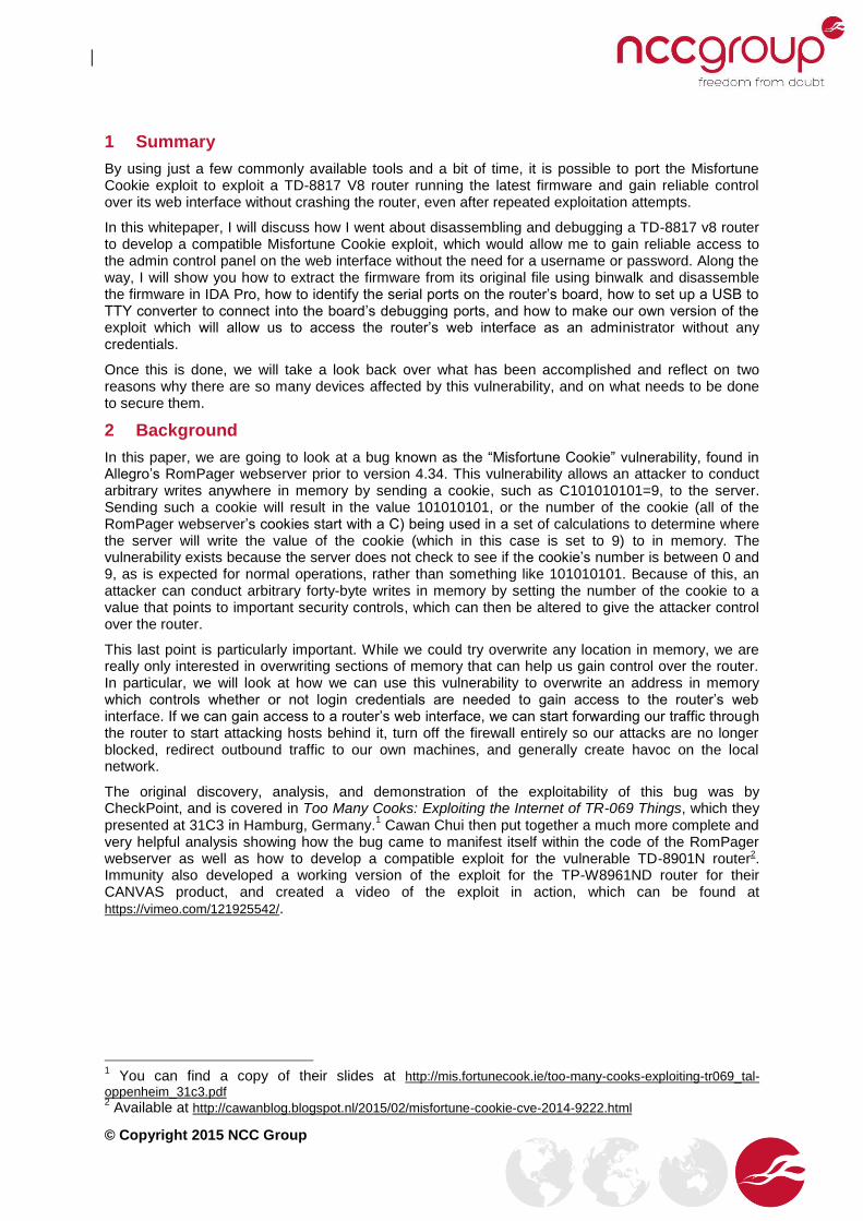
If we run file on these extracted files, we can see that both of them now turn up as data files. If we
run strings 55833 | grep –i copyright we can see that we have successfully extracted the
firmware, as identified by the copyright string at the very bottom which identifies the router as running on a MIPS32_M14K CPU:
© Copyright 2015 NCC Group
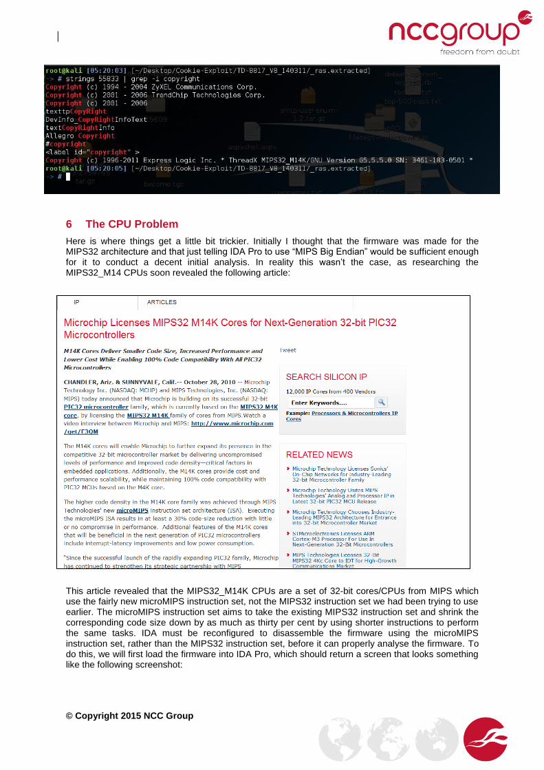
6 The CPU Problem
Here is where things get a little bit trickier. Initially I thought that the firmware was made for the MIPS32 architecture and that just telling IDA Pro to use “MIPS Big Endian” would be sufficient enough for it to conduct a decent initial analysis. In reality this wasn’t the case, as researching the MIPS32_M14 CPUs soon revealed the following article:
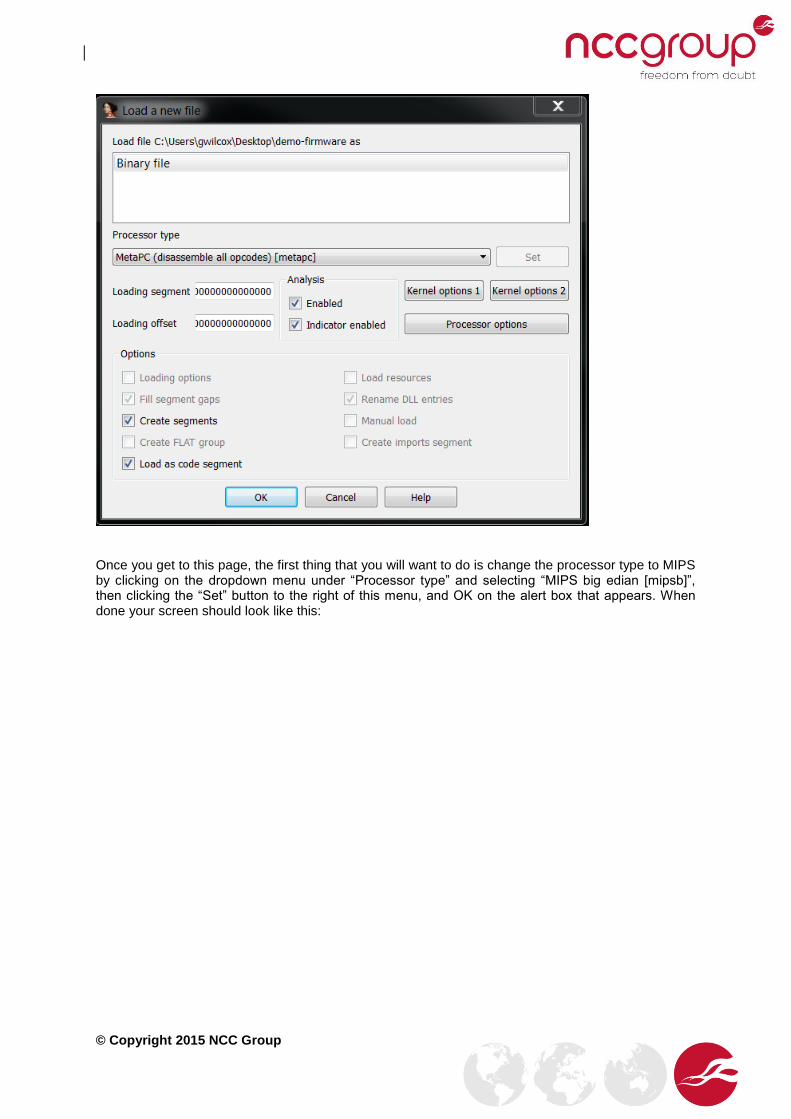
This article revealed that the MIPS32_M14K CPUs are a set of 32-bit cores/CPUs from MIPS which use the fairly new microMIPS instruction set, not the MIPS32 instruction set we had been trying to use earlier. The microMIPS instruction set aims to take the existing MIPS32 instruction set and shrink the corresponding code size down by as much as thirty per cent by using shorter instructions to perform the same tasks. IDA must be reconfigured to disassemble the firmware using the microMIPS instruction set, rather than the MIPS32 instruction set, before it can properly analyse the firmware. To do this, we will first load the firmware into IDA Pro, which should return a screen that looks something like the following screenshot:
© Copyright 2015 NCC Group
Once you get to this page, the first thing that you will want to do is change the processor type to MIPS by clicking on the dropdown menu under “Processor type” and selecting “MIPS big edian [mipsb]”, then clicking the “Set” button to the right of this menu, and OK on the alert box that appears. When done your screen should look like this:

© Copyright 2015 NCC Group
Now that we have told IDA that we are going to be loading a binary from a big-endian MIPS processor, we need to tell it to not use the MIPS instruction set, but rather microMIPS. To do this, first click on the button titled “Processor options”. You should get the following screen:

© Copyright 2015 NCC Group
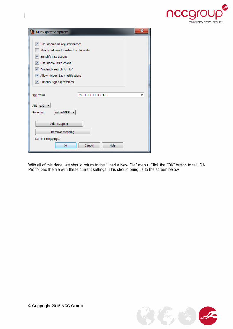
If you look under “Encoding”, we can see that we are currently using the instruction set “MIPS16e”. If we click on this dropdown menu we can see that there is an option to set this to “microMIPS”. Set the encoding to “microMIPS” using this menu, and press OK. For reference the screen should look like this before you press OK:
© Copyright 2015 NCC Group
With all of this done, we should return to the “Load a New File” menu. Click the “OK” button to tell IDA Pro to load the file with these current settings. This should bring us to the screen below:

© Copyright 2015 NCC Group
Click “OK” here, and on the next set of warnings that IDA Pro throws at us. This should take us to the following screen:

© Copyright 2015 NCC Group
IDA Pro will probably ask you about a feature called “Proximity View”. Click No on this prompt (it’s okay if you click Yes as well, either option is fine) and then hit the space bar to return back to your initial screen.
Immediately we notice a problem with IDA’s initial analysis. There are a lot of sections that IDA has marked as yellow in the navigation bar at the top. This means that IDA Pro decided to skip analysis of these sections for some reason. In order to get IDA Pro to analyse these sections, we will need to rebase the entire program to an appropriate address. Thanks to some help from Cedric Halbronn (@saidelike), I determined that the most appropriate address to rebase the program would be 0x80020000, which would make most of the firmware’s hardcoded addresses point to the correct locations in memory. (On a side note, it has been discovered that many other routers also seem to be based at this memory location, so you may wish to rebase the program to this address if IDA Pro’s initial analysis is not returning much). To rebase the program, select Edit->Segments->Rebase Program. You should see the following screen:

© Copyright 2015 NCC Group
We want to enter 0x80020000 into the value box to change the base address of the image. After the change our screen should now look like this:
Press “OK” and wait a while for IDA Pro to redo its initial analysis. Once done, we should see that it finds a lot more functions within the code (and henceforth, a lot more sections of the navigation bar are marked as blue for regular functions rather than yellow for unexplored).

© Copyright 2015 NCC Group
At this point I had to spend several days analysing the file and manually going through each of the segments to define unexplored areas as code or data. After more experience of these routers, I now
realise this process can be simplified. Go to the “strings” sub-menu and search for “do not need”.
You should see the string “Do not need password authentication for configuration!\r\n”.
If you click on this string and press X on your keyboard, you should see all the XREFs, or cross-references to the string. If you manage to get this working, you should be able to find the segment of code you are after, at which point using the C button on the keyboard defines the surrounding memory locations as code. If you cannot find the string, what you need to do is use the C button to define areas of memory as code starting from the beginning of the file, until this string appears within the “strings” sub-menu. The references to the strings you are looking for tend to occur at the beginning of the file, and the vulnerable code occurs shortly afterwards.
Once I had navigated through the code and had defined the required sections as code or data, I was left with an IDA database that looked like this: (notice how most of the yellow unexplored areas now show up within IDA as regular functions):

© Copyright 2015 NCC Group
Following along with Cowan’s work3, we see that the “Do not need password authentication for
configuration!\r\n” string within the firmware corresponds to an built in option to toggle on/off the
need for a valid username + password combination to be used to access the router’s web interface. This can be seen within the firmware starting at around address 0x8002F174:
3 http://cawanblog.blogspot.nl/2015/02/misfortune-cookie-cve-2014-9222.html
© Copyright 2015 NCC Group
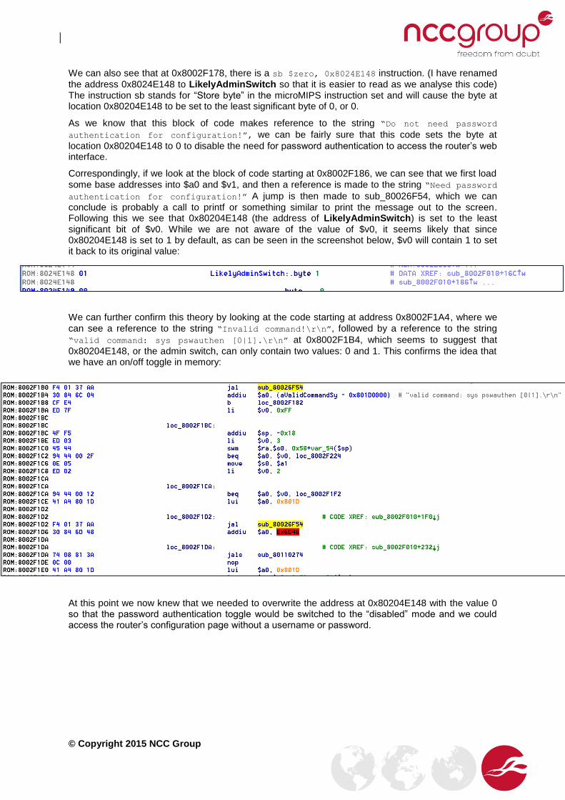
We can also see that at 0x8002F178, there is a sb $zero, 0x8024E148 instruction. (I have renamed
the address 0x8024E148 to LikelyAdminSwitch so that it is easier to read as we analyse this code) The instruction sb stands for “Store byte” in the microMIPS instruction set and will cause the byte at location 0x80204E148 to be set to the least significant byte of 0, or 0.
As we know that this block of code makes reference to the string “Do not need password
authentication for configuration!”, we can be fairly sure that this code sets the byte at
location 0x80204E148 to 0 to disable the need for password authentication to access the router’s web interface.
Correspondingly, if we look at the block of code starting at 0x8002F186, we can see that we first load
some base addresses into $a0 and $v1, and then a reference is made to the string “Need password
authentication for configuration!” A jump is then made to sub_80026F54, which we can
conclude is probably a call to printf or something similar to print the message out to the screen. Following this we see that 0x80204E148 (the address of LikelyAdminSwitch) is set to the least significant bit of $v0. While we are not aware of the value of $v0, it seems likely that since 0x80204E148 is set to 1 by default, as can be seen in the screenshot below, $v0 will contain 1 to set it back to its original value:
We can further confirm this theory by looking at the code starting at address 0x8002F1A4, where we
can see a reference to the string “Invalid command!\r\n”, followed by a reference to the string
“valid command: sys pswauthen [0|1].\r\n” at 0x8002F1B4, which seems to suggest that
0x80204E148, or the admin switch, can only contain two values: 0 and 1. This confirms the idea that we have an on/off toggle in memory:
At this point we now knew that we needed to overwrite the address at 0x80204E148 with the value 0 so that the password authentication toggle would be switched to the “disabled” mode and we could access the router’s configuration page without a username or password.

© Copyright 2015 NCC Group
7 Opening the Case
Now that we have analysed the firmware and have a likely candidate for where the web management password disabling switch is located, we need to open the case so that we can connect into the router’s debugging ports and obtain proper debugging information. To start off, flip the case upside down. You should see the sticker on the bottom of the board with information about the router. To the right and left of the bottom of this sticker you should see two round screw holes. You will need to unscrew both of these screws using a small Phillips-head screwdriver. If you are attacking a different router to the TR-8817, you may find the screws are underneath the rubber caps designed to prevent the board from sliding around.
Next, find the back of the case. It should look similar to this:
This part is especially tricky to do, even after you get the board open the first time. What you’ll want to do is look at where the scratches are on the board above, right on the gap between the two pieces of plastic. If you look on the left side of the image, to the left of the ON/OFF power button, you’ll see there is a similar gap between the two pieces of plastic. You need to crack open both sides of the board by using your fingernails or a flat-headed screwdriver to forcibly open these gaps wide enough, and keep prying them open on both sides until the top part of the casing comes off and you are left with the bottom part of the casing and the board itself:

© Copyright 2015 NCC Group
Carefully pull the back of the board up then pull it away from you (aka away from the back of the router and the plastic casing for the buttons). You should now be left with the board itself:

© Copyright 2015 NCC Group
If you look carefully at the board you will see that there are a number of round holes on the board, numbered TP1 to TP6. Starting with TP1 to TP4:
And now TP5 and TP6 (Please ignore the pin already soldered into TP5. That was my work not TP-LINK’s):

© Copyright 2015 NCC Group
7.1 Identifying Pin Purpose
Now that we have identified some candidate pins (TP0 to TP6), we need to figure out what the purpose of each one is. For this, I would recommend that you reference the excellent guide on identifying serial ports by devttys04.
You should be able to find that TP4 is the ground port by touching TP4 with one of the voltmeter’s probes and the metal shielding of the Ethernet port with the other, powering on the router, and seeing that the voltmeter gives a volt reading of 0, or no current running through the device.
For the transmit pin, you should be able to identify it as TP5 by touching TP5 with one probe and the metal shielding of the Ethernet port with the other, then rebooting the device. Upon boot, the voltage should start at around 3.3 volts, then drop down to about 2.4 volts, before fluctuating between the two, and then finally coming back up to a steady 3.3 volts.
Finally, for the receive pin, the voltage should either start out low and then be pulled up high upon rebooting the router, or it should be left floating rapidly around a few hundred millivolts. You should be able to identify TP6 as the receive pin. If you have any trouble doing this, please refer to devttys0’s guide, as he discusses this in much more detail.
7.2 Connecting the USB Adapter to the Pins
Now that we have identified the ports, we need to connect the USB to TTY serial adapter to the board. To begin with, cut off three breakaway pins from the set that you have brought and solder them into TP4, TP5 and TP6. You may find you need someone to hold the board while you solder, as the pins have a tendency to fall out of their holes quite easily. Once you have soldered the breakaway pins in, connect three of your jumper wires onto the pins and take note of which colour wire corresponds to which port. In my case I used the blue wire for TP4, or the ground, black for the receive port, or TP6, and white for TP5, or the transmit port:
4 Available at http://www.devttys0.com/2012/11/reverse-engineering-serial-ports/

© Copyright 2015 NCC Group
On the USB end, we will need to switch things up slightly. The ground wire will still be the same, so connect the same cable that you used for the ground (blue in my case) to the pin labelled “GND” on the USB adapter. However, when you get to the data ports, we will need to switch them around. Remember that whatever we transmit from one computer needs to be received by the other. Therefore we will connect our black receive line from the board into the “TXD”, or transmit, port on the USB adapter, and we will connect our white transmit line from the board into the “RXD”, or receive, port on the USB adapter:
8 Identifying the Baud rate with /dev/ttys0’s Baudrate.py Tool
We have now set everything up on the hardware side, but we still haven’t identified a crucial element that is needed for us to connect: the baud rate. Each device has its own baud rate, used to connect to the device. There are several common baud rates that most devices stick to, but there is no obligation for a device to use any specific baud rate for its communications. The easiest way to identify the baud rate is to first connect the USB adapter (still connected to the board) into your computer and then boot into a Linux virtual machine (I used Kali Linux 2.0, so the following examples will reflect this). Note that if you are using Windows as your host machine, you will need to ensure that you are connected to the Internet, so that Windows can search for the required drivers online and install them. The USB device should work automatically without the need to install drivers if you are using Linux.
Once the USB adapter is connected and the drivers are installed, go to your virtual machine and click on (I am assuming you are using VMWare Player or VMWare Workstation here) VM->Removable Devices->Cygnal Integrated CP2102 USB to UART Bridge Controller->Connect (Disconnect from Host). Click “OK” on the warning that comes up, and then log in to your Linux virtual machine.
While we now have the USB adapter connected to our virtual machine, we still need to identify what device it comes up as within the virtual machine. On my machine it came up as /dev/ttyUSB0, but it may be slightly different on yours. Once you have identified your device, and download baudrate from https://baudrate.googlecode.com/files/baudrate-1.0.tar.gz. Untar the file, and then navigate into the src directory:

© Copyright 2015 NCC Group
At this point, run baudrate.py, and then turn on your device. You should see the router’s startup information start scrolling onto the screen. As soon as this comes up, press CTRL-C. Don’t wait until the end of the messages, or you will not be able to stop baudrate.py cleanly and thus save the necessary configuration file.
You should see a message from baudrate.py that it detected a valid baud rate on 115200. It will now
prompt you to save the configuration to a minicom file so you can connect to the device though the
minicom serial client. Type in a file name and press enter. The program should then generate a
configuration file with the given name and will prompt you to run minicom immediately. Enter “n”, and
the program should cleanly exit. You can see all of this in the following screenshot:

© Copyright 2015 NCC Group
9 Connecting Into the Router with Minicom
At this point you need to install minicom onto your Linux machine. If you are on a Debian-based machine, or one that uses apt-get, this is easily done by executing sudo apt-get install minicom. Once the installation has completed, we should now be able to connect into the device by
executing minicom testRouter and then turning the router on and then off again. If done right, we
should get something like this:

© Copyright 2015 NCC Group
If you press “enter”, you should get a prompt asking you to enter a password:
Enter the default password of “admin” and you should get dropped into a shell-like prompt.
10 Triggering the Crash with Router Debugging Output
With our serial/debugging line into the router set up, let’s try crashing the router once again and seeing what debugging information we can acquire. For reference, here is the file that we created earlier, which we will use to crash the router:

© Copyright 2015 NCC Group
Next, lets’s connect the Ethernet port into the computer and run dhclient –r eth0 followed by
dhclient –i eth0, to obtain an IP address from the router for our Linux virtual machine:
Finally let’s go ahead and run the script. We should see the following error on the router side:
The router crashed and we can see that there was an access exception while trying to write to the address 0x71068874. This is quite far away from the admin switch at 0x8024E148, but let’s note down this address for now and carry on.
© Copyright 2015 NCC Group
11 Running Test Cases to Identify the Algorithm Used
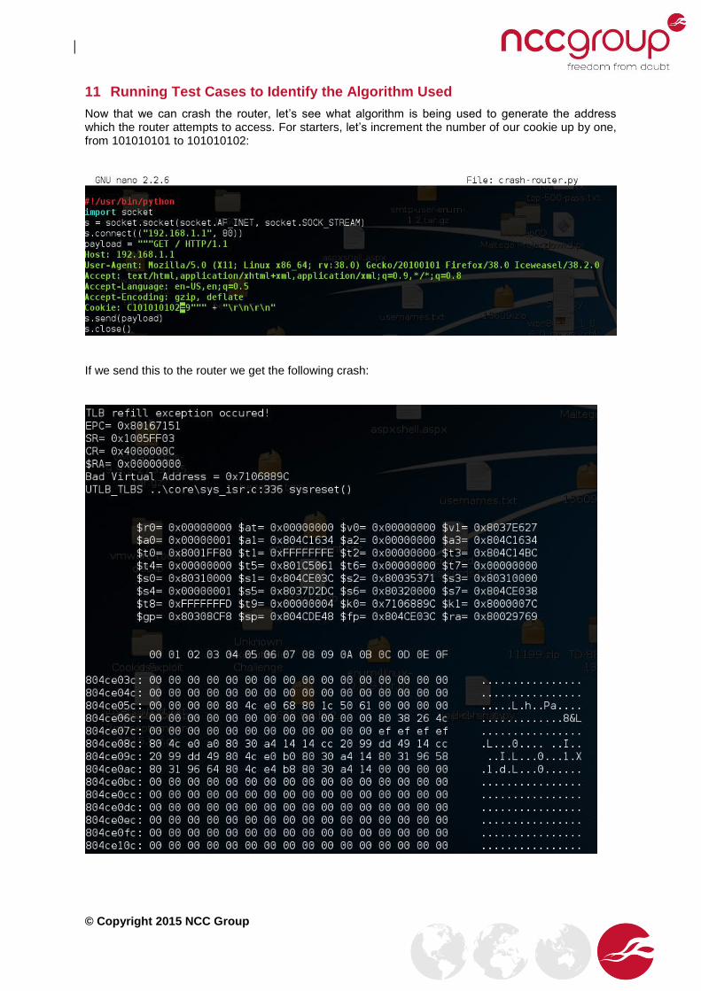
Now that we can crash the router, let’s see what algorithm is being used to generate the address which the router attempts to access. For starters, let’s increment the number of our cookie up by one, from 101010101 to 101010102:
If we send this to the router we get the following crash:

© Copyright 2015 NCC Group
A quick check between the two numbers (0x7106889C - 0x71068874) reveals that there is a difference of 0x28 or 40 in decimal, meaning that every time we increment the cookie’s number by 1 we will write 40 bytes further into memory.
11.1 Calculating the Correct Address from Test Cases
With the knowledge of the algorithm being used, we should be able to do some simple maths to calculate the cookie number needed to overwrite the admin switch located at 0x8024E148:
0x8024E148 – 0x7106889C = 0xF1E58AC
0xF1E58AC = 253647020 in decimal
253647020 / 40.0 = 6341175.5
101010102 + 6341175.5 = 107351277.5
It looks like we should be using the cookie number C107351277 to overwrite the admin switch in memory. The only other question now is what we should do about the remainder part, or the .5, which is left over from our division.. 40 x 0.5 = 20, so we need to overwrite twenty bytes before we reach our admin switch in memory. Thus if we set the cookie to a value of twenty “B”s followed by a null byte (\x00), we should be able to overwrite the twenty addresses before our switch, set the switch to 0 (\x00), and switch off the password requirements for the router’s login page.
12 Testing the Address
Now we copy over our crashing script and make a few modifications so we can exploit the vulnerability. We will change the cookie’s number from 101010102 to 107351277 so we overwrite the correct address in memory. We will also change the 9 into twenty “B”s so we overwrite the twenty bytes before our switch, and follow it up by a null byte (“\x00” in Python) to set the switch to 0.
© Copyright 2015 NCC Group
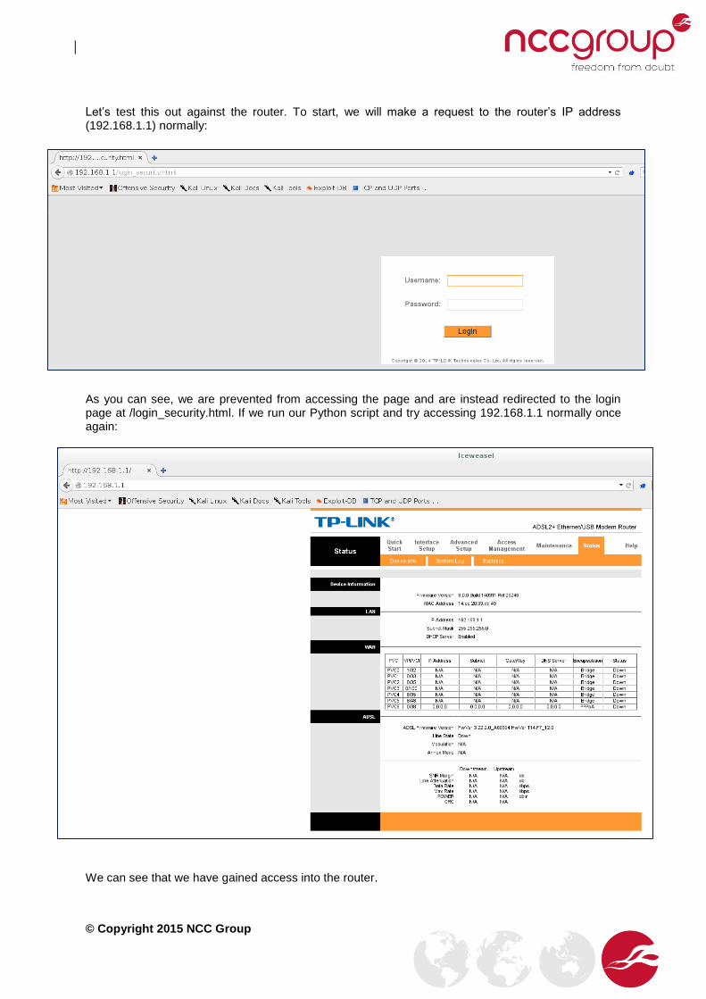
Let’s test this out against the router. To start, we will make a request to the router’s IP address (192.168.1.1) normally:
As you can see, we are prevented from accessing the page and are instead redirected to the login page at /login_security.html. If we run our Python script and try accessing 192.168.1.1 normally once again:
We can see that we have gained access into the router.

© Copyright 2015 NCC Group
13 Conclusion
As one can see, this is a serious and real bug that affects many devices worldwide. Despite the lack of public discussion surrounding the exploitation of this bug, we have demonstrated how simple it is to create a working and functional exploit that allows one to gain access to the web interface of affected routers and alter their settings to gain access to internal networks residing behind the router’s firewall.
At the time of writing, Shodan found 11,733,766 routers running RomPager/4.07, the most popular vulnerable version of the vulnerable Allegro RomPager webserver running on routers today. While some of these routers could have gone offline by the time of writing, the chances are that the majority of them are still online and are still running a vulnerable version of Allegro RomPager.
Part of the reason that this is the case is that a lot of people simply don’t bother to patch/update their routers or are unaware that they need to do so and just deploy them in their default configuration. This can result in routers sitting in the wild for years on end without getting the necessary patches, which may contribute to some of the figures that we see here.
The primary reason for this large number however is that a lot of the device manufacturers simply haven’t yet issued a firmware update to fix the Misfortune Cookie vulnerability. Take the TD-8817 v8 router that we just disassembled and analysed. At the time of writing, the V8 router is the very latest TD-8817 router that TP-LINK is offering to the public, and the firmware we disassembled is the very latest firmware available for this router, and yet it is still vulnerable to the Misfortune Cookie vulnerability, as we have demonstrated in this blog.
Until manufactures start releasing patches for their vulnerable firmware, people are unfortunately going to be stuck with what they have, unless they try and flash their router with alternative firmware (a process that will most likely void the router’s warranty) which is not vulnerable to Misfortune Cookie. Unfortunately, most people will not have the required knowledge nor expertise to do this, resulting in many Internet-facing routers being left vulnerable to this issue.
Hopefully by demonstrating how simple this exploit is to debug and recreate, and the level of access it gives an unauthenticated attacker, I have helped to show just how much of an impact this exploit has on the general public and their home security, and have helped to prove that the Misfortune Cookie exploit is more serious than most people are making it out to be. If you have any questions, concerns, or would like to point out any errors in this whitepaper, please feel free to contact me at [email protected]


