Page 1
AN ONTOLOGY-BASED APPROACH TO REQUIREMENTS REUSE PROBLEM IN
SOFTWARE PRODUCT LINES
A THESIS SUBMITTED TO
THE GRADUATE SCHOOL OF NATURAL AND APPLIED SCIENCES
OF
MIDDLE EAST TECHNICAL UNIVERSITY
BY
ELIF KAMER KARATAS
IN PARTIAL FULFILLMENT OF THE REQUIREMENTS
FOR
THE DEGREE OF MASTER OF SCIENCE
IN
COMPUTER ENGINEERING
AUGUST 2012
Page 2
Approval of the thesis:
AN ONTOLOGY-BASED APPROACH TO REQUIREMENTS REUSE PROBLEM IN
SOFTWARE PRODUCT LINES
submitted by ELIF KAMER KARATAS in partial fulfillment of the requirements for the de-
gree of Master of Science in Computer Engineering Department, Middle East Technical
University by,
Prof. Dr. Canan Ozgen
Dean, Graduate School of Natural and Applied Sciences
Prof. Dr. Adnan Yazıcı
Head of Department, Computer Engineering
Dr. Aysenur Birturk
Supervisor, Computer Engineering Dept., METU
Examining Committee Members:
Prof. Dr. Ferda Nur Alpaslan
Computer Engineering Dept., METU
Dr. Aysenur Birturk
Computer Engineering Dept., METU
Assoc. Prof. Dr. Ahmet Cosar
Computer Engineering Dept., METU
Dr. Cevat Sener
Computer Engineering Dept., METU
Tolga Ipek, M.Sc.
Manager, ASELSAN
Date:
Page 3
I hereby declare that all information in this document has been obtained and presented
in accordance with academic rules and ethical conduct. I also declare that, as required
by these rules and conduct, I have fully cited and referenced all material and results that
are not original to this work.
Name, Last Name: ELIF KAMER KARATAS
Signature :
iii
Page 4
ABSTRACT
AN ONTOLOGY-BASED APPROACH TO REQUIREMENTS REUSE PROBLEM IN
SOFTWARE PRODUCT LINES
Karatas, Elif Kamer
M.S., Department of Computer Engineering
Supervisor : Dr. Aysenur Birturk
August 2012, 66 pages
With new paradigms in software engineering such as Software Product Lines, scope of reuse
is enlarged from implementation upto design, requirements, test-cases, etc. In this thesis an
ontology-based approach is proposed as a solution to systematic requirement reuse problem
in software product lines, and the approach is supported with a reuse automation tool. A
case study is performed on the projects of an industrial software product line using hereby
proposed solution and then based on the evaluated metrics it’s reported that the content of
requirements specifications documents can be prepared upto 80% by derivation of reusable
requirements.
Keywords: Software Product Lines, Reusable Requirements, Ontology modeling
iv
Page 5
OZ
YAZILIM URUN HATLARINDA ONTOLOJI TABANLI GEREKSINIM YENIDEN
KULLANIMI
Karatas, Elif Kamer
Yuksek Lisans, Bilgisayar Muhendisligi Bolumu
Tez Yoneticisi : Dr. Aysenur Birturk
Agustos 2012, 66 sayfa
Yazılım muhendisligi dunyasında yeniden kullanım bilindik bir kavram olmakla beraber,
guncel paradigmalarla yeniden kullanılabilir kavramların seviyesi kaynak kod yanında tasarım,
gereksinim ve testleri de kapsayacak sekilde degismistir. Bu tez calısması kapsamında, yazılım
urun hatlarında gereksinim yeniden kullanımının sistemli bir sekilde saglanabilmesi icin on-
toloji tabanlı bir cozum ortaya konmus, ayrıca yeniden kullanım surecini desteklemek amacıyla
bir otomasyon aracı gelistirilmistir. Onerilen yontem, durum calısması olarak endustriyel bir
yazılım urun hattında kullanıma alınmıs, bu surecte elde edilen deneyimler ve alınan olcumler
paylasılmıstır.
Anahtar Kelimeler: Yazılım urun hattı, Yeniden kullanılabilir gereksinimler, Ontoloji mod-
elleme
v
Page 6
to my dear father Huseyin Karatas
vi
Page 7
ACKNOWLEDGMENTS
First I would like to thank my supervisor Dr. Aysenur Birturk for her guidance, motivation
and patience during my research. I thank my team members at Aselsan Inc. for their feedback
and support to my research, especially Mr. Barıs Iyidir for sharing his domain experience. I
thank my team leader Mrs. Evrim Kahraman for her tolerance and motivation during this
process. I thank my department manager Mr. Tolga Ipek for accepting to take part in the
thesis committee. I thank my father for giving me a life full of books, dreams and ideals. I
thank Kezi for her valuable advice throughout my life. I thank Sule for the delicious food she
cooked for me during these three years. I thank Mr. Anderson for not giving up and making
me believe in the path that I chose. Finally I would like to thank TUBITAK for the scholarship
it provided during my graduate education.
vii
Page 8
TABLE OF CONTENTS
ABSTRACT . . . . . . . . . . . . . . . . . . . . . . . . . . . . . . . . . . . . . . . . iv
OZ . . . . . . . . . . . . . . . . . . . . . . . . . . . . . . . . . . . . . . . . . . . . . v
ACKNOWLEDGMENTS . . . . . . . . . . . . . . . . . . . . . . . . . . . . . . . . . vii
TABLE OF CONTENTS . . . . . . . . . . . . . . . . . . . . . . . . . . . . . . . . . viii
LIST OF TABLES . . . . . . . . . . . . . . . . . . . . . . . . . . . . . . . . . . . . x
LIST OF FIGURES . . . . . . . . . . . . . . . . . . . . . . . . . . . . . . . . . . . . xi
CHAPTERS
1 INTRODUCTION . . . . . . . . . . . . . . . . . . . . . . . . . . . . . . . 1
1.1 Software Product Lines (SPLs) . . . . . . . . . . . . . . . . . . . . 1
1.2 Software Requirements . . . . . . . . . . . . . . . . . . . . . . . . 3
1.3 Motivation . . . . . . . . . . . . . . . . . . . . . . . . . . . . . . . 6
2 RELATED WORK . . . . . . . . . . . . . . . . . . . . . . . . . . . . . . . 8
2.1 Domain Modeling Approaches . . . . . . . . . . . . . . . . . . . . 8
2.1.1 Feature Modeling . . . . . . . . . . . . . . . . . . . . . . 8
2.1.1.1 Limitations of Feature Modeling . . . . . . . 9
2.1.2 Ontology Modeling . . . . . . . . . . . . . . . . . . . . . 11
2.2 Requirements Reuse Applications . . . . . . . . . . . . . . . . . . . 12
2.3 Product Configuration Problem . . . . . . . . . . . . . . . . . . . . 14
3 PROPOSED SOLUTION . . . . . . . . . . . . . . . . . . . . . . . . . . . . 17
3.1 Domain Knowledge: Fire Control SPLs . . . . . . . . . . . . . . . . 18
3.1.1 Fire Control SPL Reference Architecture . . . . . . . . . 19
3.2 Domain Modeling . . . . . . . . . . . . . . . . . . . . . . . . . . . 22
3.2.1 Domain Requirements . . . . . . . . . . . . . . . . . . . 23
3.2.2 Domain Concepts . . . . . . . . . . . . . . . . . . . . . . 26
viii
Page 9
3.3 Reuse Mechanism . . . . . . . . . . . . . . . . . . . . . . . . . . . 32
3.3.1 Ontology-based Requirements Derivation Tool: OntSRDT 33
3.4 Reusable Requirements Management . . . . . . . . . . . . . . . . . 33
4 CASE STUDY . . . . . . . . . . . . . . . . . . . . . . . . . . . . . . . . . 36
4.1 Conduction of Case Study . . . . . . . . . . . . . . . . . . . . . . . 36
4.2 Metrics and Evaluations . . . . . . . . . . . . . . . . . . . . . . . . 37
5 DISCUSSION . . . . . . . . . . . . . . . . . . . . . . . . . . . . . . . . . . 41
6 CONCLUSION . . . . . . . . . . . . . . . . . . . . . . . . . . . . . . . . . 42
REFERENCES . . . . . . . . . . . . . . . . . . . . . . . . . . . . . . . . . . . . . . 45
APPENDICES
A EXAMPLES . . . . . . . . . . . . . . . . . . . . . . . . . . . . . . . . . . 48
A.1 A Simple Configuration Example . . . . . . . . . . . . . . . . . . . 48
A.2 Sample Requirements Specifications . . . . . . . . . . . . . . . . . 59
ix
Page 10
LIST OF TABLES
TABLES
Table 4.1 Computed metrics for FCS-P1 . . . . . . . . . . . . . . . . . . . . . . . . 39
Table 4.2 Computed metrics for FCS-P2 . . . . . . . . . . . . . . . . . . . . . . . . 39
x
Page 11
LIST OF FIGURES
FIGURES
Figure 1.1 SPL Activities . . . . . . . . . . . . . . . . . . . . . . . . . . . . . . . . 2
Figure 1.2 History of reuse . . . . . . . . . . . . . . . . . . . . . . . . . . . . . . . 3
Figure 1.3 Knowledge pyramid of software phases . . . . . . . . . . . . . . . . . . . 4
Figure 1.4 Product Line Requirement Types . . . . . . . . . . . . . . . . . . . . . . 5
Figure 2.1 An example feature model . . . . . . . . . . . . . . . . . . . . . . . . . . 9
Figure 2.2 Feature model extensions . . . . . . . . . . . . . . . . . . . . . . . . . . 10
Figure 3.1 Solution architecture . . . . . . . . . . . . . . . . . . . . . . . . . . . . . 18
Figure 3.2 Fire control domain and interactions . . . . . . . . . . . . . . . . . . . . . 19
Figure 3.3 Fire Control Reference Architecture . . . . . . . . . . . . . . . . . . . . 20
Figure 3.4 An abstraction of proposed solution model . . . . . . . . . . . . . . . . . 22
Figure 3.5 Textual Requirement Representation . . . . . . . . . . . . . . . . . . . . . 23
Figure 3.6 Parametric Requirement Representation . . . . . . . . . . . . . . . . . . . 24
Figure 3.7 Complex Requirement Representation . . . . . . . . . . . . . . . . . . . . 25
Figure 3.8 Complex requirement instance . . . . . . . . . . . . . . . . . . . . . . . . 25
Figure 3.9 Classification of System environment . . . . . . . . . . . . . . . . . . . . 26
Figure 3.10 Frame for system environment concept . . . . . . . . . . . . . . . . . . . 27
Figure 3.11 Example ActionThing instance . . . . . . . . . . . . . . . . . . . . . . . 30
Figure 3.12 classification of control panel . . . . . . . . . . . . . . . . . . . . . . . . 31
Figure 3.13 Classification of Missions . . . . . . . . . . . . . . . . . . . . . . . . . . 31
Figure 3.14 A fire control software frame . . . . . . . . . . . . . . . . . . . . . . . . 32
Figure 3.15 Configuration flow . . . . . . . . . . . . . . . . . . . . . . . . . . . . . . 34
xi
Page 12
Figure A.1 configuration step1 . . . . . . . . . . . . . . . . . . . . . . . . . . . . . . 48
Figure A.2 configuration step2 . . . . . . . . . . . . . . . . . . . . . . . . . . . . . . 49
Figure A.3 configuration step3 . . . . . . . . . . . . . . . . . . . . . . . . . . . . . . 49
Figure A.4 configuration step4 . . . . . . . . . . . . . . . . . . . . . . . . . . . . . . 50
Figure A.5 configuration step5 . . . . . . . . . . . . . . . . . . . . . . . . . . . . . . 50
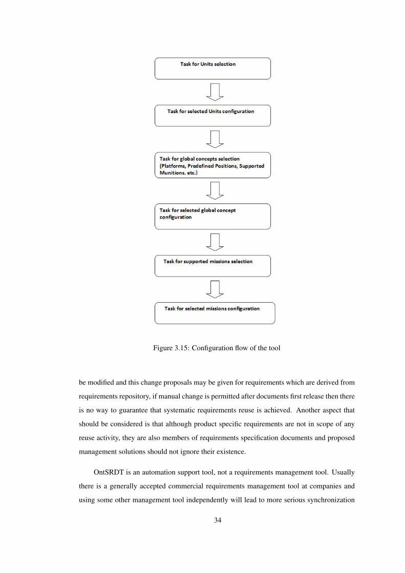
Figure A.6 configuration view after step5 . . . . . . . . . . . . . . . . . . . . . . . . 51
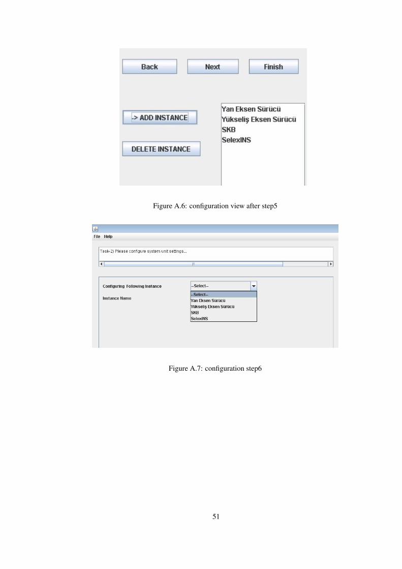
Figure A.7 configuration step6 . . . . . . . . . . . . . . . . . . . . . . . . . . . . . . 51
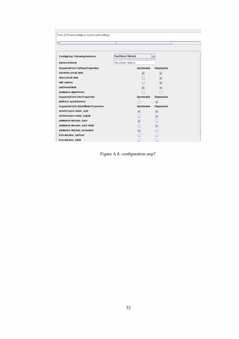
Figure A.8 configuration step7 . . . . . . . . . . . . . . . . . . . . . . . . . . . . . . 52
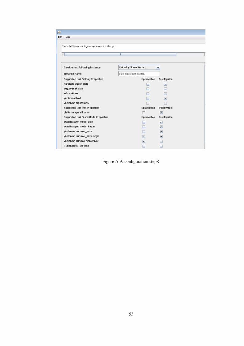
Figure A.9 configuration step8 . . . . . . . . . . . . . . . . . . . . . . . . . . . . . . 53
Figure A.10configuration step9 . . . . . . . . . . . . . . . . . . . . . . . . . . . . . . 54
Figure A.11configuration step11 . . . . . . . . . . . . . . . . . . . . . . . . . . . . . 55
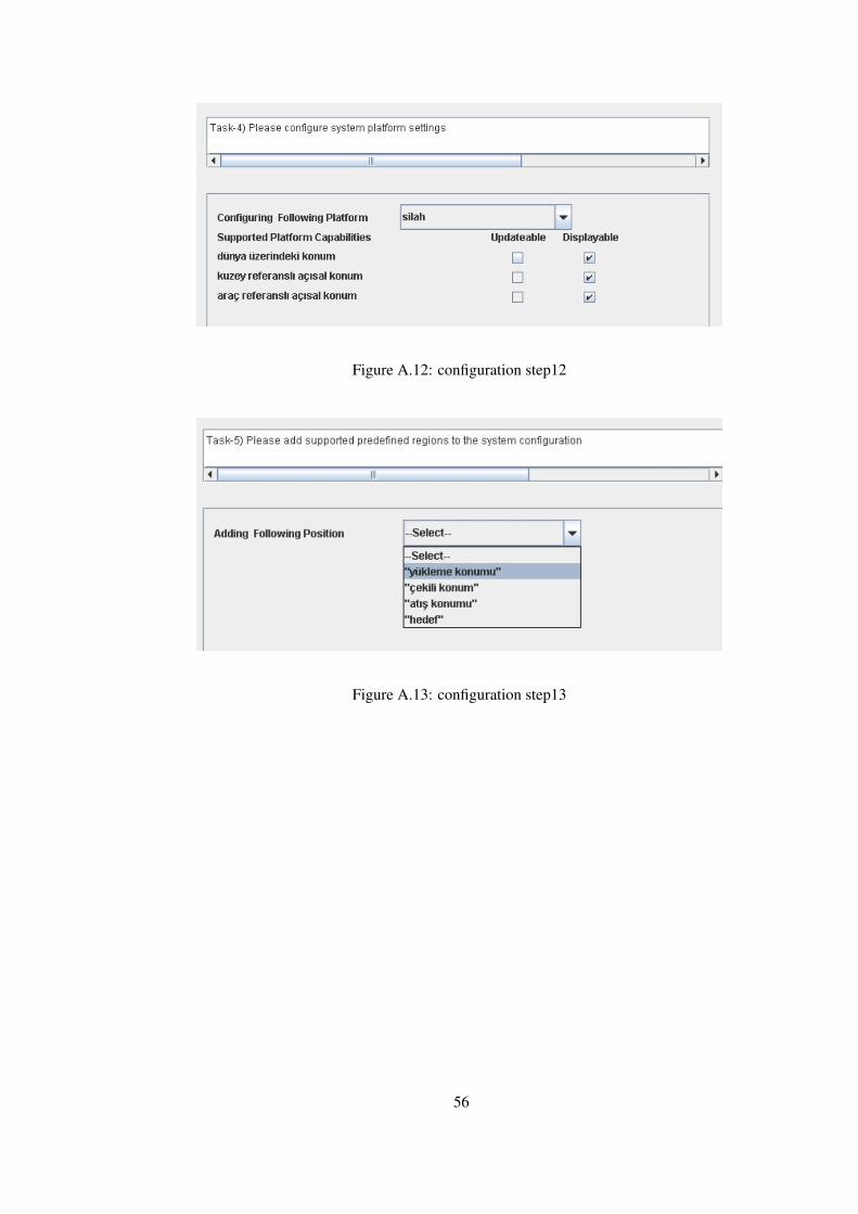
Figure A.12configuration step12 . . . . . . . . . . . . . . . . . . . . . . . . . . . . . 56
Figure A.13configuration step13 . . . . . . . . . . . . . . . . . . . . . . . . . . . . . 56
Figure A.14configuration step14 . . . . . . . . . . . . . . . . . . . . . . . . . . . . . 57
Figure A.15configuration step15 . . . . . . . . . . . . . . . . . . . . . . . . . . . . . 58
Figure A.16configuration step16 . . . . . . . . . . . . . . . . . . . . . . . . . . . . . 59
Figure A.17configuration step17 . . . . . . . . . . . . . . . . . . . . . . . . . . . . . 59
xii
Page 13
CHAPTER 1
INTRODUCTION
Software Product Line approach is popular in software engineering due to its motto of “de-
velopment with reuse”. With this approach the scope of “what is reusable” is enlarged: in
addition to implementation, reuse of artifacts like requirements, architecture and test cases
are made possible but the effort to enable their reuse is not the same. Requirements reuse is
considered to be a higher level reuse and difficult to enable in product line. In this chapter
first some background information on SPLs and software requirements is given and then the
motivation of this thesis is explained.
1.1 Software Product Lines (SPLs)
Traditional approaches to software development which includes methods such as develop-
ment from scratch, “clone and own” [1], and development with reuse libraries are no longer
feasible alternatives due to market’s evolution in which size of software products are increased
enormously, thus companies are usually specialized in a core business domain and build sim-
ilar products [2]. Furthermore increasing customer demand for better quality software causes
producers to meet shorter deadlines while minimizing cost and infamous “software crisis”
emerges [3]. Software product line (SPL) approach is popular especially in embedded soft-
ware industry to increase software quality and reduce development and maintenance costs [2].
Definition of the term “product line” is given in [4] as “ a set of software-intensive systems
sharing a common set of features that satisfy the specific needs of a particular market or mis-
sion and that are developed from a common set of core assets in a prescribed way”, which
introduces the core or domain asset term to denote the reuse repository of a product line [1].
SPL development process consists of two different phases, namely domain engineering and
1
Page 14
application engineering [5] (See Figure 1.1).
Figure 1.1: SPL Activities [5]
Domain engineering starts with domain analysis step during which product line scope is
specified and commonalities and variability among product line members are identified [5].
Based on the commonalities and variations detected at this phase architecture design is per-
formed to provide a common development framework for all members of a product line where
product variations are supported at known points. During final step of domain engineering
reusable core assets are developed for later use which can be implementation, architecture,
requirements, test cases, reports, etc.
Application engineering is the phase during which individual products are developed
from reusable core assets. Requirements for individual products are derived from the refer-
ence requirements of the product line domain [5] and only the requirements that are valid for
that individual product are implemented. As a result of intensive effort put forward during
domain analysis phase, effort needed for development, test and management of new systems
is largely reduced compared to traditional reuse approaches [1]. Studies in [6, 7, 4] point out
that with SPL development, considerable improvement in terms of productivity, quality and
time to market is possible.
Essence of SPL lies in the paradigm shift it starts from traditional single system devel-
opment to product family development whose success is highly dependent on the quality of
2
Page 15
domain knowledge. Now, opportunistic reuse is replaced with a planned and systematic reuse
which requires to be supported by automation tools for efficiency
Figure 1.2: History of reuse in software: modified from [8]
1.2 Software Requirements
Software requirements provide the specifications for desired behavior and functionalities of
a product. This knowledge constitutes a base for the other phases of software development
namely; design, implementation and test, see Figure 1.3.
3
Page 16
Figure 1.3: Knowledge pyramid of software phases
In our study, the term “ requirement” is used to denote software requirements.
In SPL context, Requirements Engineering (RE) processes have two goals: to define and
manage requirements within the product line and to coordinate requirements for the single
products [9]. Deployment and management of RE process is difficult especially in large,
trans-national organizations which produce complex, long lead products in multi-disciplinary
contexts [10]. RE process usually takes longer than planned and is more costly than origi-
nally budgeted for [11]. This nature of RE process often leads to immature and low quality
requirements which are highly error prone [11, 12] and dynamic and changing nature of re-
quirements have catastrophic effects on the following phases of software lifecycle. Instead
of performing RE process from scratch for each project, having stored reusable requirements
elements in a repository might highly improve to the development time, cost and quality of
the resultant products, which is a promoted idea in SPL development [12].
Requirements reuse has not get as much attention from research community as design
and implementation reuse and the proposed solution ideas have been restricted to small-scale
academic examples and largely untested for industrial or commercial capacity [13]. Factors
that make requirements reuse difficult include the existence of different notations, different
formats and different abstraction levels for requirements knowledge [12]. Product line re-
quirements are classified to three different categories (See Figure 1.4) whose reuse handling
4
Page 17
mechanisms will be different than each other .
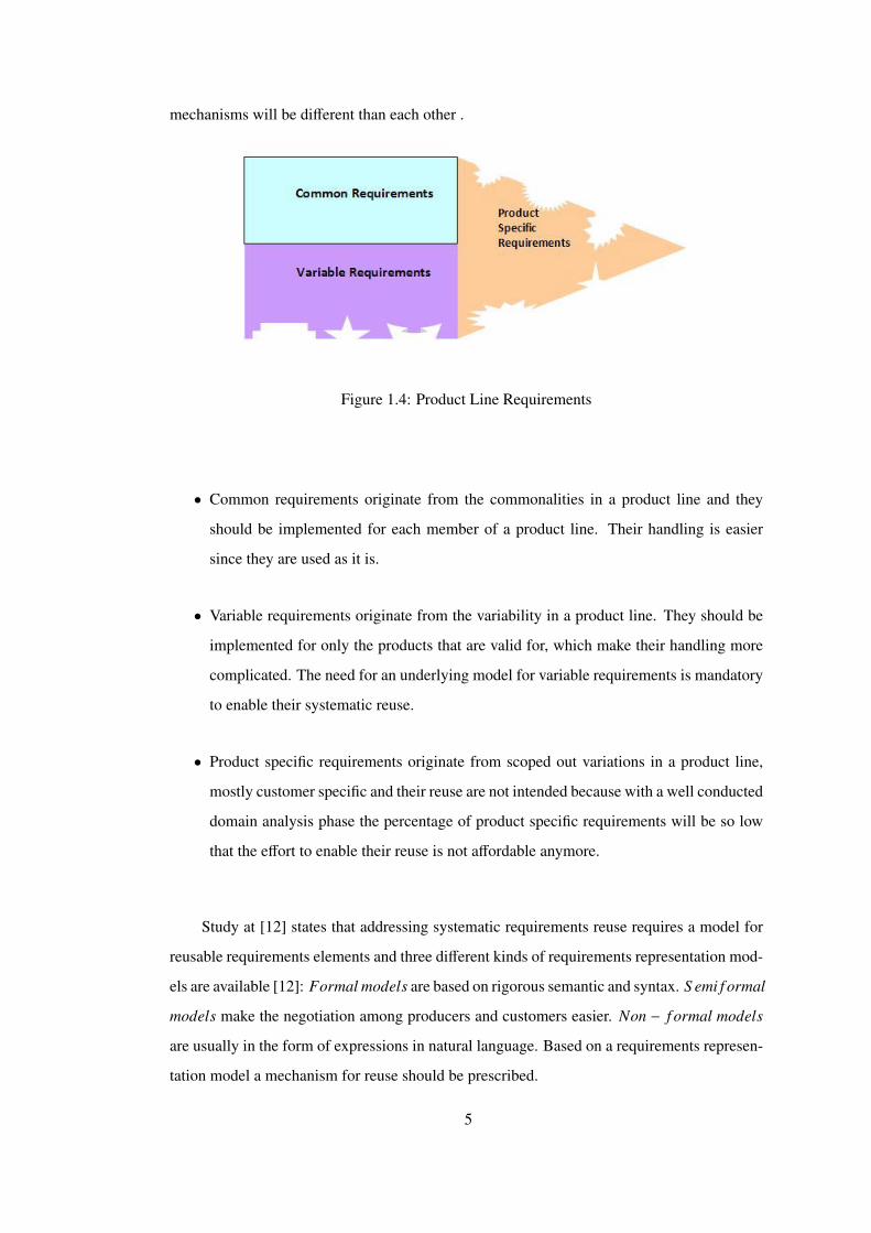
Figure 1.4: Product Line Requirements
• Common requirements originate from the commonalities in a product line and they
should be implemented for each member of a product line. Their handling is easier
since they are used as it is.
• Variable requirements originate from the variability in a product line. They should be
implemented for only the products that are valid for, which make their handling more
complicated. The need for an underlying model for variable requirements is mandatory
to enable their systematic reuse.
• Product specific requirements originate from scoped out variations in a product line,
mostly customer specific and their reuse are not intended because with a well conducted
domain analysis phase the percentage of product specific requirements will be so low
that the effort to enable their reuse is not affordable anymore.
Study at [12] states that addressing systematic requirements reuse requires a model for
reusable requirements elements and three different kinds of requirements representation mod-
els are available [12]: Formal models are based on rigorous semantic and syntax. S emi f ormal
models make the negotiation among producers and customers easier. Non − f ormal models
are usually in the form of expressions in natural language. Based on a requirements represen-
tation model a mechanism for reuse should be prescribed.
5
Page 18
1.3 Motivation
SPL approach enables mass-production of a family of related products in software industry
and its proposed systematic reuse strategy can be adopted at any phase of software develop-
ment but the benefits of systematic reuse at each phase will be different. Consider a product
line in which there is no systematic reuse at requirements engineering phase: Requirements
specifications should be written for each instance of the product line and these documents are
either going to be created from scratch or copied from existing specifications for similar sys-
tems and then modified which is inefficient in time aspect and leads to low quality, unstandart
specifications.
Similar systems appear to have similar functionalities, thus documenting requirements
specifications for similar system from scratch or first copying then manually editing is a time
waste in the sense that same work is repeatedly performed by possibly different people, which
introduces uncontrolled differences in resultant specification documents. There may be a con-
trol list to write good specifications in natural language, but even if the structure of the sen-
tences can be controlled with some little sentence analysis it’s not possible to avoid from a vast
source of semantic differences and ambiguities. Requirements knowledge is mostly the re-
sult of domain expertise and depending on the experience level of the authors and knowledge
sharing among them knowledge reflected to specification documents varies. Another problem
which is a result of multi-source requirements specifications is that editors may decide to fol-
low different abstraction levels independent from each other which disables the visibility of
some knowledge in some of documents and its difficult to be sure of these kind of knowledge
supressions do not occur in documents, furthermore there is no formal mechanism to check
that the selected abstraction level covers necessary information and consistent throughout the
whole document.
Uncontrolled variations among requirements specifications annihilate the potential ad-
vantages of domain commonalities and reduces the efficiency of domain variability handling.
Starting with these unpredictable requirements its difficult to obtain high quality results at
later phases of software development. Incomplete, missing, erroneous or ambiguous require-
ments are followed by incorrect design solutions, implementation errors or faulty test results.
Especially the quality of test phase outputs is directly dependent on the quality of require-
ments specifications due the fact that for each requirement specification there should be a
6
Page 19
corresponding test case and missing information and semantic ambiguity is directly trans-
ferred to test case specifications. For example if some domain requirement is not documented
its related behavior in the product is not formally tested and test cases written for ambiguous
requirements result in false negatives or false positives which decreases the confidence to a
software product.
To sum up following problems are identified as a result of not reusing software requirements:
• content and abstraction level diversity in documents of similar products
• textual representation diversity in documents of similar products
• high time costs for preparation of documents for similar products
• less feedback among documents of similar products
It’s obvious that not adopting systematic reuse in requirements engineering phase dis-
ables the advantages introduced with SPL approach and jeopardize the overall quality of a
product line. Although above listed problems can be eliminated by enabling requirements
reuse, this subject has not get much attention in research community until recently [13] which
means methods proposed for requirements reuse are not mature enough yet and there are
two well-known obstacles on the way of systematic requirements reuse: one is the lack of
efficient methods for domain commonality/variability modeling and second is the lack of ef-
ficient mechanisms for documentation of product line requirements [14]. Motivation of this
thesis is to develop a practical solution to efficient requirements documentation problem for
SPLs.
7
Page 20
CHAPTER 2
RELATED WORK
Related work can be classified into domain modeling approaches, existing applications of
requirements reuse, and product configuration problem. Each is discussed in turn.
2.1 Domain Modeling Approaches
The systematic discovery and exploitation of commonality across related software systems
is fundamental technical requirement for achieving successful software reuse [15]. For a
successful reuse application the commonality and variability of a domain should be identi-
fied and modeled appropriately, which increases the importance of selected domain modeling
technique. Three different types of representation models can be listed: formal models are
built on rigorous semantic and syntax (i.e ontology models), semiformal models make the
knowledge sharing easier among users of the knowledge, and non-formal models are usually
expressions in natural language [12]. Since pure non-formal models are not suitable for sys-
tematic reuse activities they are not mentioned in the following subsections. Feature modeling
and ontology modeling are discussed in details as formal knowledge representations.
2.1.1 Feature Modeling
Feature modeling is an increasingly popular technique for commonality and variability model-
ing in Software Product Line Engineering (SPLE) [16] especially for feature oriented domain
analysis (FODA)[17]. The term feature is defined in [18] as “a prominent or distinctive user-
visible aspect, quality, or characteristic of a software system or systems ”. A feature model
8
Page 21
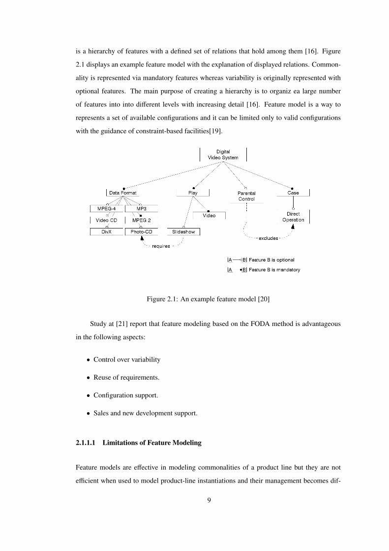
is a hierarchy of features with a defined set of relations that hold among them [16]. Figure
2.1 displays an example feature model with the explanation of displayed relations. Common-
ality is represented via mandatory features whereas variability is originally represented with
optional features. The main purpose of creating a hierarchy is to organiz ea large number
of features into into different levels with increasing detail [16]. Feature model is a way to
represents a set of available configurations and it can be limited only to valid configurations
with the guidance of constraint-based facilities[19].
Figure 2.1: An example feature model [20]
Study at [21] report that feature modeling based on the FODA method is advantageous
in the following aspects:
• Control over variability
• Reuse of requirements.
• Configuration support.
• Sales and new development support.
2.1.1.1 Limitations of Feature Modeling
Feature models are effective in modeling commonalities of a product line but they are not
efficient when used to model product-line instantiations and their management becomes dif-
9
Page 22
ficult [14]. Basic feature modeling consists of a hierarchy of features and a propositional
formula to represent knowledge [16] whose descriptive power is limited. Reported concerns
with basic FODA expressions are related on how to express domain knowledge of certain
configurations, such as default values, configuration implications and constraints while re-
taining the simplicity [22], since the strength of basic feature models lies in their simplicity
and intuitiveness [16]. There are a number of extensions proposed to basic feature models to
handle the above listed problems. Multi-level feature trees [23] are proposed in order to dealt
with the complex hierachy generated by the feature model, which are promising but untested
solutions to management problem of feature models [14]. Feature attributes of basic types
are allowed whereas adding attributes invites complex constraints [16]. Another extension
is cloning which enables the existence of features with cardinality greater than one [16] and
which potentially invites a new class of constraints, such as constraints over set of clones
[16]. Reference attribute is another extension that may point to another feature in a feature
configuration and only meaningful in the presence of cloning [16].
Other extensions to feature models are available but they do not influence the configura-
tion or semantics of a feature model [16]. In summary feature models are efficient represen-
tations to capture and convey commonality knowledge of a domain. But the basic form is not
enough to efficiently represent, reason over and manage variability on a domain, thus some
extensions are defined on basic feature models which increases the representation power (See
Figure 2.2) while inviting additional complexity to a model whose power lies in its simplicity
[16].
Figure 2.2: Feature model extensions [24]
10
Page 23
2.1.2 Ontology Modeling
In computer science, ontology is considered as a formal representational artifact for specifying
the semantics of some knowledge in a certain domain [25] and it should represent a shared
conceptualization in order to be useful [26]. A common definition of ontology in is given in
[27] as “an explicit specification of conceptualization”. “An ontology represents the semantics
of classes and their associations using some descriptive language coupled with first-order
logic or its decidable fragment ” [16].
Ontology modeling is considered to be advantageous in the following listed aspects [28]:
• Rich descriptive power. Being a formal representation based on first-order logics,
makes ontology a powerful knowledge description mechanism. Rich decriptive power
enable complex constraint to be defined according to the nature of a domain [16].
• Reasoning. Use of ontologies enable reasoning over existing knowledge to derive facts
that are not explicitly expressed in the model. Constraint propagation and constraint
solving mechanisms are also supported [16].
• Semantic interoperability. Domain ontologies are the most important part of the Seman-
tic Web [29],they enable knowledge sharing between different knowledge-base applica-
tions, without ontologies web is not semantically interoperable because it is originally
designed for direct human processing of information presented [29].
Different paradigms for ontology modeling are available, among them two widely used
paradigms are OWL and Frames [30]; although they are built on top of constructs such as
class, properties, facet, restriction etc. they display differences in their semantics, expressive
power and available tool support [30]. Some of the major differences between OWL and
Frames are listed in [30] as follows:
• In Frames ontology if truthiness of some knowledge is not explicitly specified it is
considered to be false (closed world assumption) where as in OWL if some knowledge
is not explicitly specified as false it is considered to be true (open world assumption).
• There is a single minimal model that satisfies each of the assertions in a frame ontology
whereas in OWL multiple models that satisfy the assertions in the ontology are possible.
11
Page 24
• In Frames constraints on a class define the necessary conditions that must hold for all
the instances of that class, whereas in OWL sufficient conditions can also be defined.
• In Frames, reasoner checks if the defined constraints are satisfied, whereas in OWL
consistency check of the ontology is done while trying to build a model to satisfy all
the assertions in the model. Default reasoning is one f the key strengths of Frames
over OWL, since in the former default values are used to fill partial knowledge and
exceptions are supported.
• In OWL, set of classes and instances are disjoint and it is not possible to use classes
as property values and OWL have a poor representation power of numeric expressions
which disables the expression of quantitative relations.
• In OWL, complex expression can be built using intermediate concepts anonymously
(without having to name it prior to use), which reduces the number of explicit facts in
the model. Frames do not have anonymous concept support.
• In OWL, set operations over class descriptions are allowed and also transitive properties
can be modeled, which are non existing features in Frames.
Based on the above characteristics of OWL and Frames, the nature of domain and the
application that will run on top of that domain model have a major effect on the selection of
suitable ontology modeling paradigm.
2.2 Requirements Reuse Applications
Reuse is not a new concept in software community, traditional reuse techniques that are sup-
ported by object oriented programming such as polymorphism, encapsulation and inheritance
are used by programmers to write modular and to some extent reusable code [31]. Reuse
libraries [32] are another traditional reuse approach which is based on storing any previous
solution of the development process for later use. But with the emerge of SPL development,
the concept of what is reusable, changed dramatically. In addition to implementation, now it
is possible to reuse requirements, design templates, test cases, reports, etc. Effort for enabling
reuse of different assets and also benefits gained from their reuse are different from each other.
12
Page 25
Although enabling requirements reuse have an overall affect in the performance of a
product line [33], there is not much research on the subject until recently [14], thus solution
domain is not mature enough. which results in the proposed solutions to be usually restricted
to small-scale academic examples and untested in terms of industrial or commercial capacity
[13].
Existing research on requirements reuse indicates that RE is a highly knowledge inten-
sive process [11, 28, 14] thus knowledge based solutions become increasingly popular [28].
For example potential uses of ontologies are listed in [28] as:
• representation of requirements model,
• domain knowledge acquisition,
• representation of domain knowledge
In [14] following RE problems, that are related to knowledge intensive activities are listed:
• insufficient requirements traceability,
• lack of systematic requirements reuse,
• lack of integration of RE activities,
• communication problem in distributed development.
Since SPL development is about systematic reuse, lack of systematic requirements reuse
is an important problem for product line success. In [34] two key challanges for requirements
reuse in product line development is identified as effective techniques for domain analysis,
and how to document product line requirements. Also the diversity of representations and the
existence of different levels of requirements description are factors that make requirements
reuse difficult [12].
Feature oriented and ontology based methods are the two mostly used methods in do-
main analysis [13, 28]. In [33] an approach to capture and validate software requirements
using OWL and reasoning technology is presented. This mentioned approach extends OWL
with closed world constraints to check the completeness of requirements model against well
13
Page 26
established metrics such a ISO/IEC 9126. OntoREM [11] is an ontology-driven requirements
engineering methodology, which introduced in order to improve requirements quality while
reducing the efforts (ie. development and maintenance) for requirements reuse. Although it
is not a study on software requirements reuse, it is important in the sense that it reports eval-
uation results of the proposed method in a case study on aircraft operability domain, which
increases the confidence in ontology based methods in requirements reuse problem. A fea-
ture oriented study in [13] proposes a requirements management process in the concept of
reuse in product lines and shares the experience with the proposed method in embedded soft-
ware industry. The findings of the study can be listed as features are efficient mechanisms
for reusable requirements and reusable test cases development. In [12] a requirements meta
model to define reusable requirement is proposed, contribution of the study is the introduction
of a meta model to enable requirement reuse in domains where semiformal representations are
used to capture requirements information. Another study that focuses on reusing traditional
textual requirements is presented in [35], which proposes a reuse model based on “derived re-
quirements” concept and reports engineering efforts savings with requirements reuse as high
as 61
In summary, domain analysis and requirements documentation is two important prob-
lems in the way systematic requirements reuse that waits for efficient solutions. Feature ori-
ented and ontology based approaches are available for domain modeling. Successful applica-
tions of ontology based solutions have been reported. In addition to development of reusable
requirements, methods to define process for reuse and management of reusable requirements
are needed. Although the findings in [11, 13, 35] are promising, in general the ideas are either
restricted to small-scale academic examples or untested in genuine industrial or commercial
capacity [13].
2.3 Product Configuration Problem
“Given a set of customer requirements and a product family description, the configuration
task is to find a valid and completely specified product structure among all alternatives that
the generic structure describes” [36]. While domain analysis and modeling are the important
problems of domain engineering phase of SPL development, product configuration is the
major problem of application engineering phase in which software products of a company
14
Page 27
are configured from a set of components, according to the needs of individual customers.
Even after a commonality and variability modeling solution is presented, an industrial scale
SPL may include very large number of different instantiations of the underlying model, thus
selecting valid product configurations for individual systems is a difficult problem to solve
manually [37], thus product con f igurators are needed.
Product configurators are considered to be among the most succesful applications of
artificial intelligence technology [36] but usually adopted for the configuration process of
non-software products, and product configurators used for non-software products give results
as abstract products , but during software product configuration it’s also possible to give re-
sult as the product’s itself [38]. Different configuration approaches are listed in literature
such as rule-based, model-based and case-based approaches [36]. Each of these approaches
have a different underlying ontology that is used to represent the domain knowledge, domain
entities and relations that hold between these entities [36]. Logic-based, resource-based and
constraint-based representations are commonly used for the implementation of model-based
approaches [36].
In [39],the fact that a configurable product and the configurator software should be de-
veloped in parallel is highlighted which makes knowledge acquisition and maintenance of
configuration knowledge bases critical. This study [39] states that the existence of different
proprietary knowledge representations which are not integrated into standard software de-
velopment processes makes knowledge based configuration more complicated and proposes
UML usage to construct a configuration knowledge base.
In [38] a model-based product derivation methodology for application in software-intensive
domains is proposed. A novel aspect of the study is stated as the combination of tool-
supported configuration and realization into one process for deriving software products [38].
Experiences gained from the experiments with industrial partners are also reported.
Following important properties for a product cofiguration solution methodology is listed
in [40]:
• explanation, product training, and help desk support
• reasoning schemeas that handle incomplete or ambiguous information
15
Page 28
• inconsistency detection, error handling and retraction
In [41] an interactive configuration approach is presented which is a combination of
configuration and content-based recommendation of product lines. In [42] a model-based
framework for automated product derivation is presented relying on an independent model-
based design layer. It’s proposed that this design bridges the gap between feature models and
product implementations.
16
Page 29
CHAPTER 3
PROPOSED SOLUTION
Requirements engineering(RE) is considered to be a knowledge intensive process in software
lifecycle which encourages the use of knowledge based techniques in this area of software
engineering[use], depending on this fact an ontology based approach is proposed for require-
ments reuse problem in SPLs. In this chapter, the proposed solution, basic information about
the problem domain, phases of domain modeling studies and the OntSRDT tool built on this
domain knowledge is discussed in detail.
RE and architecting are the two initial phases of software lifecycle whose major out-
comes are requirements specifications and architecture documents which contain dense knowl-
edge that has prominent effects on the success of a project and depending on the fact that these
two phases have an interweaved relationship and overlapping knowledge [14] with common-
alities, some RE problems can be solved by reusing solutions for architectural knowledge
(AK) management [14] and in literature proposed methods for reuse of AK are based on for-
mal domain models. Accordingly, this thesis proposes an ontology based domain knowledge
formalization for SPLs, ontology modeling is preferred over feature modeling due to their de-
scriptive power and also to overcome management problems of feature models that proliferate
with increased variability. Reuse is achieved by a tool support which is based on an interactive
product configuration scenario which guides the user to enter required information to instan-
tiate a valid product of the product line and the related requirements with this configuration
is enlisted automatically. Requirements formalization and support tool design are performed
such that enlisted requirements have unique identifiers to accomplish the management of re-
quirements of the domain ontology. With this feature it is possible to import the outputs
of automation tool to a commercial requirements management tool and any changes due to
following updates on domain ontology can be reflected upon previously created documents.
17
Page 30
Figure 3.1 illustrates the solution architecture:
Figure 3.1: Solution architecture
According to this solution architecture, a GUI Handler is developed to provide some
forms to user in order to collect information about product configuration and to document
the configuration related requirements. GUI Handler is in communication with an Ontology
Handler which enables controlled access to underlying domain ontology and provides the in-
formation exchange required by GUI Handler. Domain ontology and domain repository is the
part where the model and instances of different concepts in the model are stored respectively.
3.1 Domain Knowledge: Fire Control SPLs
Before going into details of domain modeling, it is useful to provide some introductory in-
formation about the target domain in this study.“ Fire control in general encompasses all
operations required to apply fire on a target” [43] but it can be divided into two as tactical or
technical fire control, tactical fire control is responsible for the planning and evaluation part
where technical fire control softwares are usually embedded in a weapon system and focus
on computational and mechanical operations required for that weapon system to hit a specific
target with a specific munition [43]. They operate in real-time and are mission critical,thus
18
Page 31
for this type of software determinism, system and operator safety are important. These soft-
wares are surrounded with various sensors to obtain information about the target and physical
environment of the weapon, accompanied with platforms and actuators to enable motion of
the system and also in interaction with a user control panel or tactical fire control systems.
Figure 3.2 illustrates the basic concepts in technical fire control software world.
Figure 3.2: Fire control domain and interactions [43]
3.1.1 Fire Control SPL Reference Architecture
According to the previously conducted domain analysis and architecting studies a reference
architecture [44] is agreed upon to be adopted in fire control software development. As men-
tioned in the begining of this chapter, RE and architecting are two interweaved processes
whose outputs are feedbacks to each other [14], in that sense when starting to domain model-
ing for requirements reuse in mind, its not like starting from scratch. Key concepts, relations
between them and domain rules are mostly already identified during architecting studies but
these knowledge is not formalized in a way to be machine readable and analyzable. Thus ex-
19
Page 32
isting reference architecture model (See Figure 3.3) and reports constitute as a good starting
point for the domain modeling studies and throughout this study domain model is constructed
in consistency with reference architecture which means although the structural definitions of
the domain concepts are different, the rules that hold between them should not violate the
previously defined reference architecture.
Figure 3.3: Fire Control Reference Architecture [44]
According to the above figure, there are four important main concepts in FCS Product
Line:
• S ystem Environment Concept corresponds to the various types of sensors and actua-
tors , which will be referred to as units in the rest of this document,that surround a fire
control software. Examples to these can be but not limited to inertial navigation sys-
tems (INS) for sensing vehicle movement and changes in angular position, reading the
current position of the system on earth or power control devices to manage the power
distribution of the systems, servo controllers to perform angular positioning of the plat-
forms, gun controllers to perform firing of some munitions with a specified setting, etc.
Different kinds of system environment elements are identified, their provided services
and information are explored and they are grouped into family of devices. Before our
work, this concept was the most exploited one, but their effects to product requirements
20
Page 33
were not documented explicitly.
• Capability Concept correspond to different groups of management operations that are
required for centralized management of system environment inputs and services. For
example platform management capability handles different angular inputs from differ-
ent sensors, which can be attached to different platforms, and provides data transforma-
tion between different platforms. Capabilities can be seen as guards that prevents direct
access to system environment inputs and services. They are also well defined concepts,
different groups of capabilities are identified to be used throughout the related product
line, in that sense they are similar to system environment concepts but are less open to
changes, functionalities and data of capabilities are rarely updated. Before our work,
effects of capabilities to product requirements also were not documented explicitly.
• Mission Concept is closer to end user due to its higher level of abstraction and can be
further divided into different types of missions which are basically the scenario man-
agers in a system, based on what capability world provides to them they are responsible
for the conduction of operational scenarios while assuring system safety and user spec-
ifications. Although some initial understanding on mission concept exists, it is usually
handled in a free format way rather than studying and modeling the commanality and
variability throughout the product line. Structure of mission layer and attributes do not
exist prior to this study and also their reflection to product requirements are not for-
mally studied. An important difficulty that arises with the mission concept is that most
of the domain knowledge on missions are not documented, they are usually embedded
to the product via the domain expertise knowledge of the developers and product re-
quirements corresponding to mission concepts are the ones where divergence among
requirements specification documents are most visible.
• External Inter f ace Concept is the part where user interaction enters the scene of fire
control software and also the part where everything goes hand in hand. Different types
of external interfaces can be user consoles on which some button, switch, led kind of
entities make it possible to start/stop scenarios and alert user, alternatively tactical fire
control softwares may have software interface to operate through technical fire control
softwares. Results of previous domain research [44] indicates that its difficult to model
the behavior and structure of external interface concept in isolation from other concepts
that constitutes the fire control software. This part usually includes system specific
21
Page 34
requirements and thus external interface concept modeling is not among the initial goals
of this study but still some effort is used for identification of the structure of external
interface related domain requirements.
3.2 Domain Modeling
During this study, ontology modeling approach is chosen over feature modeling due to its
richer descriptive power and suitability for formal analysis. Frame ontology paradigm is fol-
lowed. Ontology model is developed on Protege3.4.7 ontology editor because of its support
for frame ontology [45]. Final domain model should include formalizations for domain con-
cepts, constraints and domain requirements; during the modeling process, existing reference
architecture documents of the domain is used as initial input to indentify key domain concepts,
architecture models and documents are used as input to identify domain rules, previously doc-
umented requirements specifications are used as input to identify domain requirements, apart
from these codified inputs, expert knowledge is also investigated to be made explicit in the
model. We propose a solution model such that, domain requirements and domain concepts are
formalized and if some domain concept invokes a set of requirements in real world, in model
that concept is also related with these requirements, thus when a fire control software is built
up from specified domain concepts, domain requirements related to these configuration are
also built up. Figure 3.4 displays the intended solution model.
Figure 3.4: An abstraction of proposed solution model
22
Page 35
3.2.1 Domain Requirements
After analysis of existing requirements specification documents, two types of requirements
are identified:
• constant requirements that do not display variations for different products. Examples:
– Software should end laying when laying accuracy is achieved.
– Software should stop firing when ammunition empitied.
• variable requirements, that display some variations according to the product configura-
tion. Examples:
– Software should check INS connection error be f ore laying.
– Software should check INS connection error during laying.
– Software should check INS connection error during f ire.
– Software should check servo connection error be f ore f ire.
Based on above descriptions about requirements specifications, our aim in this work is
to formalize textual requirements specifications such that, both constant and variable require-
ments can be supported. Constant requirements are trivial but variable requirements needs a
mechanism to enable variations, which is the introduction of “requirement parameters”. A
requirements specification is considered to be “complex requirement” consisting of one or
more “textual requirements” and zero or more “parametric requirements”. Figure 3.5. and
3.6 displays model snapshots for introduced terms.
Figure 3.5: A snapshot from model: Textual Requirement Representation
23
Page 36
Figure 3.6: A snapshot from model: Parametric Requirement Representation
Parametric requirements are stored in repository without their actual parameters entered,
instead a textual representation is developed as place holders. Parameters will be determined
later at reuse time, with some little parsing actual values of parameters will be inserted to the
related location. Complex requirements is mainly a combination of textual and parametric
requirements, but some more information is added to its definition to also specify a template
document structure for resultant requirements specifications. See Figure 3.7 for a snapshot of
complex requirement definition. The template document structure is to group requirements to
related headings thus introduce a document hierarchy for readability.
24
Page 37
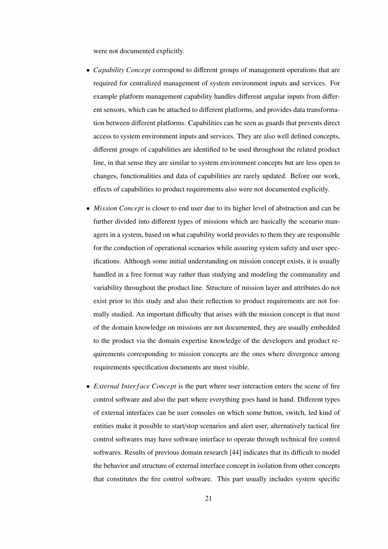
Figure 3.7: A snapshot from model: Complex Requirement Representation
After a formalization for requirements specification is developed, construction of repos-
itory of domain requirements is started, but since requirements are related with domain con-
cepts, repository construction is performed in parallel to domain modeling, while new con-
cepts are added to the model.
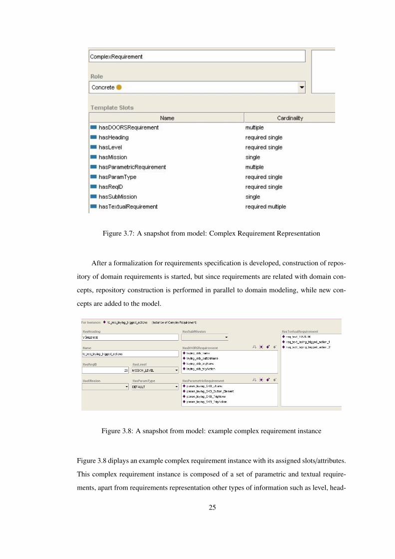
Figure 3.8: A snapshot from model: example complex requirement instance
Figure 3.8 diplays an example complex requirement instance with its assigned slots/attributes.
This complex requirement instance is composed of a set of parametric and textual require-
ments, apart from requirements representation other types of information such as level, head-
25
Page 38
ing(to be used in the template),and parameter type are also exist. For example this complex
requirement instance will appear under laying requirements heading of mission requirements
section in the document.
3.2.2 Domain Concepts
In domain study the initial effort was on answering the question “Which concepts are used
to built a fire control software?”. Reference architecture indicates some of these concepts
namely system environment, capability, mission, without giving formal definitions. Aim of
this study is to provide an ontology model that includes representations of these more general
concepts from software requirements perspective. Meaning of a concept can be divided into a
number of sub concepts, with the following base condition: if a newly introduced sub concept
is not a parameter of some requirement in the repository or has no effect on the evaluation of
domain constraints, just don’t introduce it. In this section details of the modeled concepts are
given.
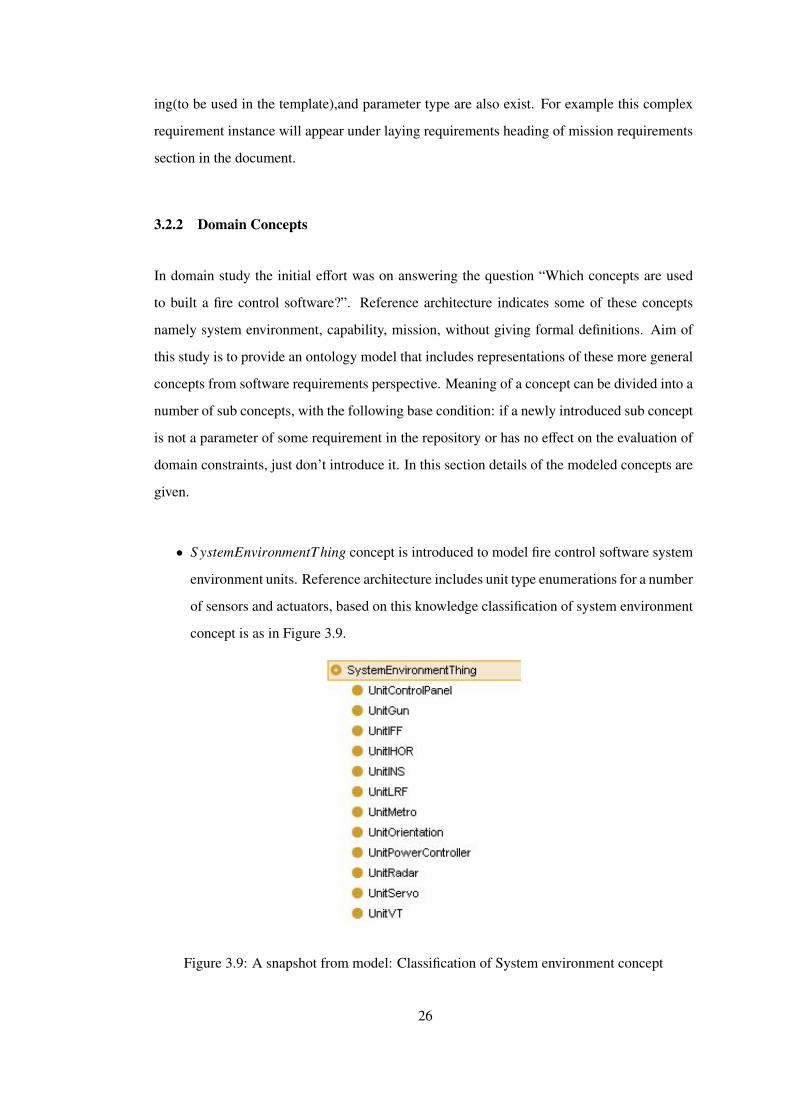
• S ystemEnvironmentThing concept is introduced to model fire control software system
environment units. Reference architecture includes unit type enumerations for a number
of sensors and actuators, based on this knowledge classification of system environment
concept is as in Figure 3.9.
Figure 3.9: A snapshot from model: Classification of System environment concept
26
Page 39
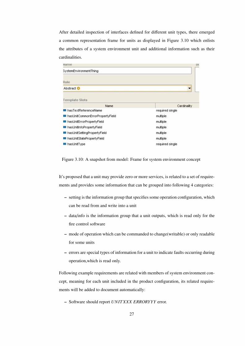
After detailed inspection of interfaces defined for different unit types, there emerged
a common representation frame for units as displayed in Figure 3.10 which enlists
the attributes of a system environment unit and additional information such as their
cardinalities.
Figure 3.10: A snapshot from model: Frame for system environment concept
It’s proposed that a unit may provide zero or more services, is related to a set of require-
ments and provides some information that can be grouped into following 4 categories:
– setting is the information group that specifies some operation configuration, which
can be read from and write into a unit
– data/info is the information group that a unit outputs, which is read only for the
fire control software
– mode of operation which can be commanded to change(writable) or only readable
for some units
– errors are special types of information for a unit to indicate faults occurring during
operation,which is read only.
Following example requirements are related with members of system environment con-
cept, meaning for each unit included in the product configuration, its related require-
ments will be added to document automatically:
– Software should report UNIT XXX ERRORYYY error.
27
Page 40
– Software should report UNIT XXX INFOYYY information.
– Software should read UNIT XXX MODEYYY mode.
– Software should write UNIT XXX S ETT INGYYY setting.
– Software should write UNIT XXX S ETT INGYYY setting.
An example unit of type INS has the following fields:
– setting: initialization time, boresight, orientation, shutdown with stored heading,
information accuracy, alignment time
– info: north referenced angle values, GPS data, initial position, vehicle moving,
remaining time to complete alignment
– mode: zero velocity update requested, initial position requested, initialization
mode, stored heading alignment mode, gyro compass alignment mode, etc.
– error: connection error, initialization error, communication error, crtical fault
• S erviceThing concept is introduced while modeling S ytemEnvironmentThing concept,
it’s known that some members of system environment are there to provide some ser-
vices while supporting information, settings or mode related to these services. A ser-
vice is modeled with a service name and a supplier instance of system environment. A
portion of services introduced to model are listed as follows:
– Angle Service provides angular information about the platform of the service sup-
porting unit.
– GPSPosition Service provides the GPS position of the service supporting unit.
– Stabilization Service provides stabilized motion of a platform
– Drive with Speed Service provides the motion of a platform with a commanded
speed.
– Drive with Position Service provides the motion of a platform to a commanded
position.
– Drive with Error Service provides the motion of a platform from its current posi-
tion as the specified error.
– Drive with Torque Service provides the motion of a platform with commanded
torque value.
28
Page 41
– Target Velocity Service provides the velocity information about a detected target.
– Firing Service provides the firing of some munition.
During service concept modeling, following feedback to current architecture is given:
Current architecture defines a “driveService” which may have the following drive modes
as enumerations: move with speed, move with position, move with error, move with
torque. This type of encoded usage of different drive services disables the detection of
configuration inconsistencies at model level. When a system environment unit arrives
its supported services are also known thus instead of encoding different service types
as enumerations a different service interface can be defined, which enables the model
based check of “each service used should be provided by some unit” rule.
• ActionThing concept is introduced to model missions which control different scenar-
ios.(which will also be introduced later). Mission scenarios can be thought as actions
and each action is triggered by some external/internal event, and that action is realized
by some mission. Figure 3.11 displays an example action instance which is the scenario
of laying to combat position, triggered by some button in the system and that action is
realized by a sub type of laying mission.
• TriggerThing concept is introduced to model different types of scenario starters in a
fire control software which is usually an external command from either a control panel
or a user interface software. Each trigger trigs an action in the software. Since most of
the triggers are caused by external interface events, although initial goal of this study
does not include a complete model of fire control software external interface, control
panel related part of external interface sub domain is studied to complete the relationhip
between a mission, an action and a trigger.
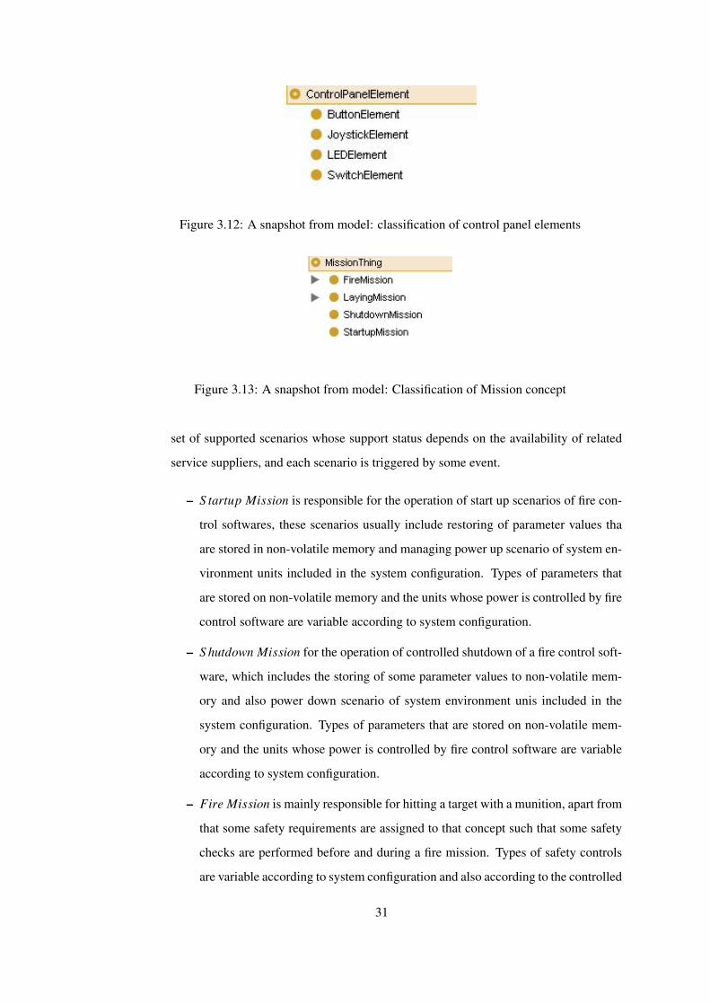
• UnitControlPanel is a special member of system environment concept which has some
additional concepts other than modes,information, errors, etc. These additional con-
cepts are grouped under a different concept named ControlPanelElement, see Figure
3.12.
A control panel element is either a button, switch, led or joystick that resides on a sys-
tem environment member of tye UnitControlPanel which has the following additional
requirements:
– Software should set the status of LEDXXX on UNITCTRLPANELYYY
29
Page 42
Figure 3.11: A snapshot from model: an example ActionThing instance
– Software should read the status of S WITCHXXX on UNITCTRLPANELYYY
– Software should read the status of BUTTONXXX on UNITCTRLPANELYYY
– Software should set the origin of JOYS T ICKXXX on UNITCTRLPANELYYY
A switch or button usually have some substates such as ON/OFF, ENABLE/DISABLE,
etc. and each state of these control panel elements are triggers of actions in a fire control
software.
• MissionThing concept is introduced to model for supported mission scenarios of a fire
control software. Reference architecture does not include any specification for mission
concept, just indicates the existence of it. Thus depending on the applications in exist-
ing projects and including expert knowledge on this subject a number of requirements
related to mission concept are enlisted and following classification is introduced (See
Figure 3.13).
Unlike units, mission types do not have much commonality in structure, since informa-
tion used and operations performed by different missions are usually disjoint. But an
underlying mechanism that is modeled with this work is that: each mission type has a
30
Page 43
Figure 3.12: A snapshot from model: classification of control panel elements
Figure 3.13: A snapshot from model: Classification of Mission concept
set of supported scenarios whose support status depends on the availability of related
service suppliers, and each scenario is triggered by some event.
– S tartup Mission is responsible for the operation of start up scenarios of fire con-
trol softwares, these scenarios usually include restoring of parameter values tha
are stored in non-volatile memory and managing power up scenario of system en-
vironment units included in the system configuration. Types of parameters that
are stored on non-volatile memory and the units whose power is controlled by fire
control software are variable according to system configuration.
– S hutdown Mission for the operation of controlled shutdown of a fire control soft-
ware, which includes the storing of some parameter values to non-volatile mem-
ory and also power down scenario of system environment unis included in the
system configuration. Types of parameters that are stored on non-volatile mem-
ory and the units whose power is controlled by fire control software are variable
according to system configuration.
– Fire Mission is mainly responsible for hitting a target with a munition, apart from
that some safety requirements are assigned to that concept such that some safety
checks are performed before and during a fire mission. Types of safety controls
are variable according to system configuration and also according to the controlled
31
Page 44
firing scenario, for example safety requirements of a stationary firing scenario are
different than the safety requirements of a non-stationary firing scenario.
– Laying Mission is mainly responsible for the motion of a platform to some other
position or with some specified speed, etc. , apart from that some safety require-
ments are assigned to that concept such that some safety checks are performed
before and during a laying mission. Types of safety controls are variable accord-
ing to system configuration and also according to the controlled laying scenario,
for example safety requirements of a non-stabilized laying scenario are different
that the safety requirements of a stabilized laying scenario.
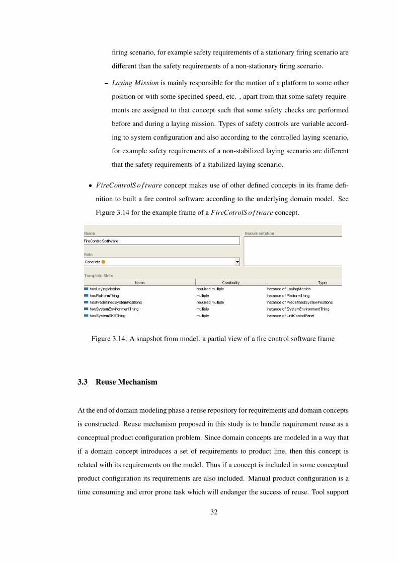
• FireControlS o f tware concept makes use of other defined concepts in its frame defi-
nition to built a fire control software according to the underlying domain model. See
Figure 3.14 for the example frame of a FireCotrolS o f tware concept.
Figure 3.14: A snapshot from model: a partial view of a fire control software frame
3.3 Reuse Mechanism
At the end of domain modeling phase a reuse repository for requirements and domain concepts
is constructed. Reuse mechanism proposed in this study is to handle requirement reuse as a
conceptual product configuration problem. Since domain concepts are modeled in a way that
if a domain concept introduces a set of requirements to product line, then this concept is
related with its requirements on the model. Thus if a concept is included in some conceptual
product configuration its requirements are also included. Manual product configuration is a
time consuming and error prone task which will endanger the success of reuse. Tool support
32
Page 45
is required at that point to decrease human errors and increase reuse efficiency.
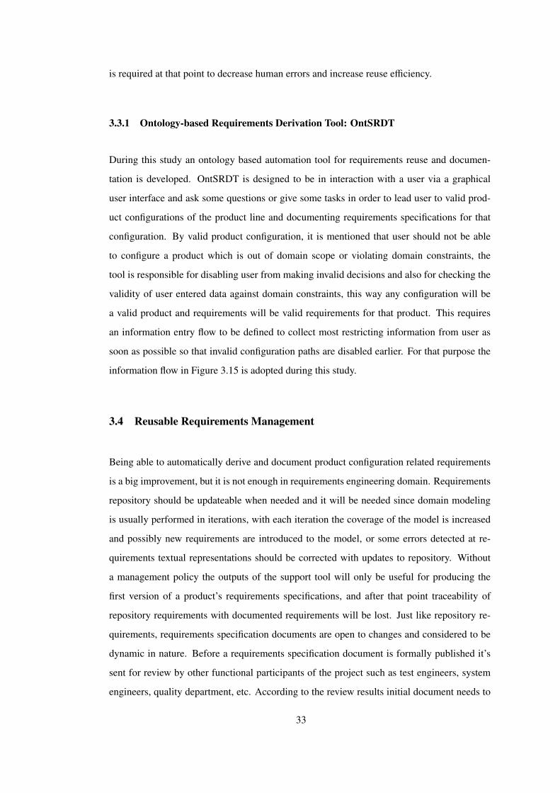
3.3.1 Ontology-based Requirements Derivation Tool: OntSRDT
During this study an ontology based automation tool for requirements reuse and documen-
tation is developed. OntSRDT is designed to be in interaction with a user via a graphical
user interface and ask some questions or give some tasks in order to lead user to valid prod-
uct configurations of the product line and documenting requirements specifications for that
configuration. By valid product configuration, it is mentioned that user should not be able
to configure a product which is out of domain scope or violating domain constraints, the
tool is responsible for disabling user from making invalid decisions and also for checking the
validity of user entered data against domain constraints, this way any configuration will be
a valid product and requirements will be valid requirements for that product. This requires
an information entry flow to be defined to collect most restricting information from user as
soon as possible so that invalid configuration paths are disabled earlier. For that purpose the
information flow in Figure 3.15 is adopted during this study.
3.4 Reusable Requirements Management
Being able to automatically derive and document product configuration related requirements
is a big improvement, but it is not enough in requirements engineering domain. Requirements
repository should be updateable when needed and it will be needed since domain modeling
is usually performed in iterations, with each iteration the coverage of the model is increased
and possibly new requirements are introduced to the model, or some errors detected at re-
quirements textual representations should be corrected with updates to repository. Without
a management policy the outputs of the support tool will only be useful for producing the
first version of a product’s requirements specifications, and after that point traceability of
repository requirements with documented requirements will be lost. Just like repository re-
quirements, requirements specification documents are open to changes and considered to be
dynamic in nature. Before a requirements specification document is formally published it’s
sent for review by other functional participants of the project such as test engineers, system
engineers, quality department, etc. According to the review results initial document needs to
33
Page 46
Figure 3.15: Configuration flow of the tool
be modified and this change proposals may be given for requirements which are derived from
requirements repository, if manual change is permitted after documents first release then there
is no way to guarantee that systematic requirements reuse is achieved. Another aspect that
should be considered is that although product specific requirements are not in scope of any
reuse activity, they are also members of requirements specification documents and proposed
management solutions should not ignore their existence.
OntSRDT is an automation support tool, not a requirements management tool. Usually
there is a generally accepted commercial requirements management tool at companies and
using some other management tool independently will lead to more serious synchronization
34
Page 47
problems with other participants of the project. Our proposal is to implement an add-on for
existing commercial requirements management tool in order to import the outputs of the de-
veloped support tool in this thesis. One more problem that arises after the output requirements
of the tool is migrated to a commercial management tool, is the reflection of changes to the
document that resides in that other tool. To handle this problem it’s decided that our support
tool should include some unique id generation mechanism for repository requirements, which
also requires the underlying model to include partial identifiers for concepts and their related
requirements. Documenting each requirement specification with a unique identifier solves
management problem of reusable requirements management. Even though updates are per-
formed on domain concepts or requirements repository, when related product configuration
is applied on support tool and outputs are imported to commercial management tool again,
unique id mechanism is enough for that tool to apply changes only to affected requirements
and preserves identifiers and specifications for other requirements.
35
Page 48
CHAPTER 4
CASE STUDY
One problem with proposed solutions for requirements reuse in software engineering is that
they are usually untested for industrial usage [13]. To support the reuse solution proposed in
this thesis with results obtained by application of it on an industrial scope product line, a case
study on fire control software product lines developed by Aselsan Inc. is planned. Conduction
details of case study and results are discussed in detail.
4.1 Conduction of Case Study
In order to evaluate content and coverage of domain ontology and automatically derived re-
quirements specified with this study, the support tool is enabled in RE of two different fire
control software projects under development, this projects will be referred to as FCS-P1 and
FCS-P2 in this document. FCS-P1 and FCS-P2 have the following general product configu-
rations:
• Servo Controller
• Gun Controller
• INS/Compass
• tracking as a type of laying mission
• fire mission
Requirements specification documents for the above product configurations are documented
by the support tool developed in this study. But since meeting the deadlines of the above
36
Page 49
project was necessary and graphical user interface of the tool was not completed at the time,
case study is conducted by performing product configuration manually inside code. Initial
goal of the case study was to display the coverage of ontology based requirements specifica-
tions thus valid product configurations are supplied to the tool. Output files of the tool are
imported to commercial requirements management tool and each document is opened to re-
view of a group of engineers from software engineering, test engineering, systems engineering
and software quality engineering departments. The information that some of the requirements
are automatically derived from a requirements repository is not shared with the review group.
After review process is completed and change proposals are reflected upon the documents
some metrics are calculated which are shared in the following section.
4.2 Metrics and Evaluations
During this case study the number of requirements in the repository is noted as 59. Initial
versions of requirement specification documents for FCS-P1 and FCS-P2 contain 264 and
304 requirements respectively. During evaluations comparison with existing systems’ re-
quirements are not preferred mostly due to their different abstraction levels than the hereby
introduced one. Thus some of the requirements documented within this study are almost in-
visible in existing documents which makes the comparison difficult. Apart from abstraction
level, quality and content of existing documents are not standard to be considered as a bases
for comparison.
Following metrics are introduced for evaluations, see Table 4.1 and Table 4.2 for com-
puted values of these metrics.
• Ratio of automatically derived requirements to overall requirements, as an indicator of
document coverage of automatically derived requirements in terms of percentage.
• Ratio of automatically derived requirements that are manually updated, as an indicator
of maturity for used requirements repository. Updated requirements are inspected and
different update types are noted, for each update type a different metric is introduced.
• Ratio of syntax updates to overall updates, indicates the ratio of updates to correct
typo mistakes and some Turkish natural language corrections about suffixes to derived
requirements. Following requirements are extracted from documents as examples:
37
Page 50
– initial requirement: Software should check that servo controller unit is clear of
Hardware error ...
– updated requirement: Software should check that servo controller unit is clear of
hardware error ...
• Ratio of naming updates to overall updates, as an indicator of a need to rename some
concepts in the document without imposing any semantic difference. Following re-
quirements are extracted from documents as examples:
– initial requirement: Software should check that “gun controller unit” is clear of
not ready to fire error ...
– updated requirement: Software should check that “gun otomation unit” is clear
of not ready to fire error ...
– initial requirement: Software should check that mode of “servo controller unit”
is ready to move ...
– updated requirement: Software should check that mdoe of “azimuth servo con-
troller unit” is ready to move ...
• Ratio of semantic updates to overall updates, as an indicator of semantically immature
requirements. Following examples are extracted from documents as examples:
– initial requirement: Software should propose an ammunition type to be fired.
– updated requirement: Software should propose an ammunition type to be fired
according to the result of ammunition proposal calculations.
• Ratio of deletions to overall updates, as an indicator of unwanted requirements due
to their irrelevance of configuration or abstraction level. Following requirements are
extracted from document as examples to deleted requirements:
– deleted requirement: Software should enable target type entry for an active target.
– deleted requirement: Software should enable target angular position entry for an
active target.
38
Page 51
Table 4.1: Computed metrics for FCS-P1
Metric Value(%)
Ratio of derived requirements to overall requirements 81.71
Ratio of manual updates on derived requirements 25.57
Ratio of deletions to overall updates on derived requirements 1.82
Ratio of syntax updates to overall updates on derived requirements 23.52
Ratio of concept renaming updates to overall updates on derived requirements 66.66
Ratio of semantic updates to overall updates on derived requirements 15.68
Table 4.2: Computed metrics for FCS-P2
Metric Value(%)
Ratio of derived requirements to overall requirements 84.38
Ratio of manual updates on derived requirements 18.50
Ratio of deletions to overall updates on derived requirements 4.76
Ratio of syntax updates to overall updates on derived requirements 19.04
Ratio of concept renaming updates to overall updates on derived requirements 78.57
Ratio of semantic updates to overall updates on derived requirements 7.14
Based on the above metrics, with the proposed solution approach most of the product
requirements can be automatically derived (81.71% - 84.38%). As previously stated after
reviews some requirements are updated manually, depending on the effects of these update
following comments are made:
• The ratio of deletions on derived requirements is less than 5%, this means our approach
mostly documents in scope requirements, not causing false positives in measurements.
• The ratio of syntax updates (19.04% - 23.52%) is an indicator of need for review of
textual fragment in the requirements repository and sentence compositions for more
natural language looking sentences, it’s detected that some sentence structures irritates
the reviewers.
• Based on the ratio of concept renaming updates (66.66%- 78.57%), depending on the
project without changing the semantics, there is a need fro flexibility in our tool design
to be able to give proper names especially to system environment units in order to
increase documents’ understandability.
39
Page 52
• Based on the ratio of semantic updates (7.14%-15.68%), it can be said that our domain
model and requirements repository are not mature enough, model should be updated in
the light of these semantic changes.
40
Page 53
CHAPTER 5
DISCUSSION
Results of the case study indicate that document coverage of automatically derived product
line requirements is acceptable, thus proposed method is promising and applicable in prac-
tice. But during this study it was not possible to perform a comperative study of our method
with existing approaches/tools since the success of the method is to a great extent dependent
on quality, scope and complexity of underlying domain model. Tools developed for other
domains can not be directly applied to the domain studied in this research, thus comparison
of our results with the results of other methods evaluated in other domains does not provide
significant information because there is no way to compare the complexity and the scope of
the underlying domain models used in different research. Since results of existing methods
in literature are not suitable for a comperative study with the hereby proposed method, for
further evaluation of our method, a set of metrics for continuous evaluation should be defined
and evaluated with updates on our approach and/or domain ontology and thus new versions
of our method will be compared against previous versions and we will be able to track the
improvements with future updates.
Another point is that evaluated metrics in this research do provide information about
document coverage of automatically derived product line requirements, but do not provide
any information about the quality improvements achieved with the proposed method. A set of
metrics should be selected and evaluated on documents created with the method introduced
in this thesis and existing documents that are created with traditional approaches, so that a
comparison in terms of requirements quality is possible.
41
Page 54
CHAPTER 6
CONCLUSION
In this thesis an ontology based solution is proposed to enable requirements reuse in a product
line to eliminate the disadvantages of not reusing software requirements. The main contribu-
tion of this work is the introduction of a practical mechanism for requirements reuse and man-
agement of these reusable requirements. Hereby proposed approach is applied in RE phase of
two different fire control software and metrics we obtained from this practice is reported. The
benefits of the proposed approach can be listed as follows:
• Requirements whose source are reference architecture or reusable components are made
visible in the documents independent from the document owners’ decision. Expert
knowledge is represented in the model such that even unexperienced engineers working
in the domain can prepare a great percentage of requirements specifications documents
by just following their knowledge about system configuration.
• Previously domain knowledge was stored in raw text documents such as reports of ar-
chitecting studies, in UML to represent reference architecture and interface definitions
in C++, the accumulated knowledge on fire control domain is not in a machine readable
form, which prevents analysis and development of assisting applications on this knowl-
edge. Studies in this thesis started the migration of knowledge from other existing for-
mats to a formal format as domain ontology. During this migration process some useful
feedbacks to architectural interfaces are generated. For example current architecture de-
fines a “DriveServiceInterface” which encodes different drive services as enumerations
such as drive with torque or drive with speed. When a unit arrives which kind of drive
services it support is known in advance based on its interface control documents, but
embedding this knowledge as enumerations prevents the detection of improper usage
42
Page 55
of the “DriveServiceInterface” on model level. Thus, instead of enumerating different
drive services of the domain, “DriveServiceInterface” can be breakdown into sub types.
• One of the main quality indicators of a requirement statement is having one and only
one requirement in it. Traditional requirements engineering methods can not detect
these types of quality deficiencies before requirements reviewing phase. Since auto-
matically derived requirements are coming from the same source, by controlling re-
quirements in the repository in terms of their language and quality, all of the following
documents will be affected from this quality assessment.
• Document prepared by traditional methods may differ in abstraction level, by using
automatically derived requirements even if the documents are created by different level
except from product specific requirements, abstraction level is consistent throughout a
single document and throughout all product line requirements specification document.
Product specific requirements will be in minority and there will be enough time for
their careful inspection. Reuse of requirements will increase the quality of requirements
while decreasing the effort used to documenting them in the long term.
Although the results obtained from the experience gained with this study is very promis-
ing, efficiency of the proposed method is directly related to completeness and correctness of
the ontology model and quality of the tool support. Thus, following items are listed to be
studied in future:
• The coverage of the ontology model is not complete yet, which prevents its efficient
usage for some of the product line members. One way to continuously improve the
coverage is to apply this approach on the upcoming projects and collect feedbacks from
them.
• The conformity of requirements specifications in the repository to quality standards
on requirements should be checked by introducing the evaluation of required metrics.
Based on this metrics it will be possible to comment on the general quality of prepared
documents with this reuse method.
• There is more to do with the support tool, current status of OntSRDT tool is suitable to
support the requirements reuse process but it should be improved to be open to public
use as a product configurator. Also it should be updated for each new concept that
43
Page 56
affects a product configuration is introduced into model to get synchronized with the
underlying model. Current tool support is only for regular user and do not let any
changes to happen to underlying ontology model with user actions. But there is also a
need for a special user, who also cannot change the structure of the model but can add
new instances of concepts usually for system environment units. It can be enhanced to
an expert system in the future and can be used to for human training and optimization
for valid product configurations.
Above listed work items are important to keep alive the studies that started with the hereby
presented work, but application of knowledge based methods in software engineering are not
limited to RE activities. This encourages us to enhance the underlying domain model in
future such that on top of requirements, automatic test case derivation can be supported to an
extent, furthermore some relation to implementation can be supplied such that the support tool
that’s currently only used to conceptually configure a product can also be used to configure
an implementation for that product in the future.
44
Page 57
REFERENCES
[1] Colin Atkinson and et al. Component-based Product Line Engineering with UML.
Addison-Wesley, 2002.
[2] Patrick Heymans and Jean-Christophe Trigaux. Software product lines: State of the art.
Technical Report EPH3310300R0462/215315, Facultes Universitaires Notre-Dame de
La Paix, Institut d’Informatique, Rue Grandgagnage, 21, B-5000 NAMUR(Belgique),
September 2003. Project: Product Line Engineering of food Traceability Software,
Financing: Region Wallone and Fonds Socia Europeen.
[3] Kurt Bittner and Ian Spence I. Use Case Modeling. Addison-Wesley, 2003.
[4] Paul Clements and Linda Northrop. Software Product Lines, Practices and Patterns.
Addison-Wesley, 2001.
[5] Ulrike Dowie, Nicole Gellner, Sven Hanssen, Andreas Helferich, Georg Herzwurm, and
Sixten Schockert. Quality assurance of integrated business software: An approach to
testing software product lines. Universitat Stuttgart, Institute of Business Adminstration,
Chair of Information System II.
[6] Jan Bosch. Design Use of Software Architectures. Addison-Wesley, 2000.
[7] Lisa Brownsword and Paul Clements. A case study in successful product line develop-
ment. Technical Report CMU/SEI-TR-016, Carnegie Mellon University,Software Engi-
neering Institute, 1996.
[8] Linda Northrop. Software product lines: Reuse that makes business sense, 2007.
[9] Olfa Djebbi and Camille Salinesi. Red-pl, a method for deriving product requirements
from a product line requirements model. In Proceedings of the 19th International Con-
ference On Advanced Information Systems Engineering, 2007.
[10] Gerald Kotonya and Ian Sommervile. Requirements Engineering: Process and Tech-
niques. Wiley, 1998.
[11] Mario Kossmann and Mohammed Odeh. Ontology-driven requirements engineering -
a case study of ontorem in the aerospace context. INCOSE, International Symposium,
2010.
[12] Oscar Lopez, Muguel A. Laguna, and Francisco J. Garcia. Metamodeling for require-
ments reuse, 2002.
[13] Seungyun Lee and et al. Reusable sw requirements development process: Embedded sw
industry experiences. Australian Software Engineering Conference (ASWEC), 2007.
[14] Peng Liang and Paris Avgeriou. From architectural knowledge to requirements knowl-
edge management. Technical Report RUG-SEARCH-09-L02, Department of Mathe-
matics and Computing Science, University of Groningen, February 2009.
45
Page 58
[15] Ruben Prieto-Diaz. Domain analysis: An introduction. ACM SIGSOFT Software Engi-
neering Notes, 15(2):47–54, April 1990.
[16] Chang Hwan Peter Kim. On the relationship between feature models and ontologies,
2006.
[17] Kyo C. Kang, Sholom G. Cohen, James A. Hess, William E. Novak, and A. Spencer
Peterson. Feature oriented domain analysis (foda), feasibility study. Technical Re-
port CMU/SEI-90-TR-21, Carnegie-Mellon University Software Engineering Institute,
November 1990.
[18] American Heritage. The American Heritage Dictionary. Springer, Houghton Mifflin,
Boston, MA, 1985.
[19] Don S. Batory. Feature models, grammars and propositional formulas. Software Prod-
uct Lines, 9th International Conference, SPLC, 2005.
[20] Detlef Streitferdt, Periklis Sochos, Christian Heller, and Ilka Philippow. Configuring
embedded system families using feature models.
[21] Michael Schlickm and Andreas Hein. Knowledge engineering in software product lines.
[22] Pietu Pohjalainen. Feature oriented domain analysis expressions.
[23] Mark-Oliver Reiser and Matthias Weber. Managing highly complex product families
with multi-level feaure trees. 14th IEEE International Requirements Engineering Con-
ference, 2006.
[24] Krzysztof Czarnecki, Chang Hwan Peter Kim, and Karl Trygve Kalleberg. Feature
models are views on ontologies. In Software Product Line Conference. IEEE, August
2006.
[25] Dean Allemand and James A. Hendler. Semantic web for the working ontologist: Mod-
eling in RDF, RDFS and OWL. Elseiver, 2008.
[26] Glen Dobson and Peter Sawyer. Revisiting ontology-based requirements engineering in
the age of the semantic web. in: Dependable requirements engineering of computerised
systems at npps, 2006.
[27] Thomas R. Gruber. Towards principles for the design of ontologies used for knowledge
sharing. Technical Report KSL93-04, Stanford University, August 1993.
[28] Veronica Castaneda, Luciano Ballejos, Ma. Lauro Caliusco, and Ma. Rosa Galli. The
use of ontologies in requirements engineering. Global Journal of Researches in Engi-
neering, 10(6):2–8, November 2010.
[29] Dragan Djuric, Dragan Gasevic, and Vladan Devedzic. Ontology modeling and mda.
Journal of Object Technology, 4(1), January-February 2005.
[30] Hai H. Wang and et al. Frames and owl side by side. 9 th International Protege Confer-
ence, 2006.
[31] Michel Ezran, Maurizio Morisio, and Colin Tully. Practical Software Reuse. Springer,
2002.
46
Page 59
[32] Frakes W. and Kang K. Software reuse research: Status and future. IEEE Transactions
on Software Engineering, 31(7):529–536, July 2005.
[33] Katja Siegemund, Edward J. Thomas, Yuting Zhao, Jeff Pan, and Uwe Assmann. To-
wards ontology-driven requirements engineering. In 7th International Workshop on Se-
mantic Web Enabled Software Engineering, October 2011.
[34] Betty H. Cheng and Joanne M. Atlee. Research directions in requirements engineering.
29th International Conference on Software Engineering (ICSE), 2007.
[35] Antonio Monzon. A practical approach to requirements reuse in product families of
on-board sytems. 16th IEEE Internationa Requirements Engineering Conference, 2008.
[36] Thersten Blecker, Nizal Abdelkafi, Gerold Kreuter, and Herhard Friedrich. Product con-
figuration systems: State-of-the-art, conceptualization and extensions. In 8th Maghre-
bian Conference on Software Engineering and Artificial Intelligence, May 2004.
[37] Timo Asikainen, Tomi Mannisto, and Timo Soininen. Using a configurator for mod-
elling an configuring software product lines based on feature models. In Workshop on
Software Variability Management for Product Derivation, Software Product Line Con-
ference (SPLC3), 2004.
[38] Katharina Wolter, Lothar Hotz, and Thorsten Krebs. Model-based configuration support
for software product families.
[39] Alexander Fernig, Gerhard E. Friedrich, and Dietmar Jannach. Generating product con-
figuration knowledge bases for precise domain extended uml model, 2000.
[40] Deborah L. McGuinness. The description logic hand book. Cambridge University
Press, 2003.
[41] Camille Salinesi, Raouia Triki, and Raul Mazo. Combining configuration and recom-
mendation to define an interactive product line configuration approach, 2012.
[42] Ina Schaefer, Alexander Worret, and Arnd Poetzsch-Heffer. A model-based frame-
work for automated product derivation. In lnternational Workshop on Model-driven
Approaches in Software Product Line Engineering (MAPLE), August 2009.
[43] Dr. Malcolm Morrison, Dr. Joel Sherrill, Ron O’Guin, and Deborah A. Butler. A fire
control architecture for future combat systems. The Journal of Defense Software Engi-
neering, August 2003.
[44] Aselsan Inc. A reference architecture for fire control systems. Technical Report DR-
0000-0074-R99, Aselsan Inc., November 2009.
[45] www.protege.stanford.edu, Last access on 29 August 2012.
47
Page 60
APPENDIX A
EXAMPLES
A.1 A Simple Configuration Example
Following images display the steps for a simple product configuration and resulting require-
ments specification.
Figure A.1: configuration step1
48
Page 61
Figure A.2: configuration step2
Figure A.3: configuration step3
49
Page 62
Figure A.4: configuration step4
Figure A.5: configuration step5
50
Page 63
Figure A.6: configuration view after step5
Figure A.7: configuration step6
51
Page 64
Figure A.8: configuration step7
52
Page 65
Figure A.9: configuration step8
53
Page 66
Figure A.10: configuration step9
54
Page 67
step10]configuration step10
Figure A.11: configuration step11
55
Page 68
Figure A.12: configuration step12
Figure A.13: configuration step13
56
Page 69
Figure A.14: configuration step14
57
Page 70
Figure A.15: configuration step15
58
Page 71
Figure A.16: configuration step16
Figure A.17: configuration step17
A.2 Sample Requirements Specifications
U: BIRIM AYARLARI ILE ILGILI ISLEMLER
U:21-I:1 INS AYARLARI
U:21-I:1-P:1-NP:1 Yazilim, INS baglanti kurulamadi hatasini bildirecektir.
U:21-I:1-P:2-NP:1 Yazilim, INS haberlesme hatasini bildirecektir.
U:21-I:1-P:3-NP:1 Yazilim, INS donanim hatasini bildirecektir.
U:21-I:1-P:4-NP:1 Yazilim, INS acilma hatasini bildirecektir.
U:21-I:1-P:66-NP:2 Yazilim, INS GPS baglanti hatasini bildirecektir.
U:21-I:1-P:67-NP:2 Yazilim, INS VMS baglanti hatasini bildirecektir.
U:21-I:1-P:6-NP:3 Yazilim, INS tarafindan bildirilen platformun kuzey/ufuk referansli acisal
yonelim degeri bilgisinin okunabilmesini saglayacaktir.
U:21-I:1-P:7-NP:3 Yazilim, INS tarafindan bildirilen GPS verisi bilgisinin okunabilmesini
saglayacaktir.
U:21-I:1-P:9-NP:3 Yazilim, INS tarafindan bildirilen arac hareketli bilgisinin okunabilmesini
59
Page 72
saglayacaktir.
U:21-I:1-P:10-NP:3 Yazilim, INS tarafindan bildirilen ilklenmenin tamamlanmasi icin kalan
sure bilgisinin okunabilmesini saglayacaktir.
U:21-I:1-P:6-NP:4 Yazilim, platformun kuzey/ufuk referansli acisal yonelim degeri bilgisinin
girilebilmesini saglayacaktir.
U:21-I:1-P:8-NP:4 Yazilim, ilk konum bilgisinin girilebilmesini saglayacaktir.
U:21-I:1-P:9-NP:4 Yazilim, arac hareketli bilgisinin girilebilmesini saglayacaktir.
U:21-I:1-P:49-NP:5 Yazilim, INS oryantasyon ayar(lar)inin okunabilmesini saglayacaktir.
U:21-I:1-P:48-NP:5 Yazilim, INS boresight ayar(lar)inin okunabilmesini saglayacaktir.
U:21-I:1-P:46-NP:5 Yazilim, INS ilklenme suresi ayar(lar)inin okunabilmesini saglayacaktir.
U:21-I:1-P:47-NP:5 Yazilim, INS kuzey/ufuk bilgisi hassasiyeti ayar(lar)inin okunabilmesini
saglayacaktir.
U:21-I:1-P:49-NP:6 Yazilim, INS oryantasyon ayar(lar)inin yapilabilmesini saglayacaktir.
U:21-I:1-P:48-NP:6 Yazilim, INS boresight ayar(lar)inin yapilabilmesini saglayacaktir.
U:21-I:1-P:46-NP:6 Yazilim, INS ilklenme suresi ayar(lar)inin yapilabilmesini saglayacaktir.
U:21-I:1-P:47-NP:6 Yazilim, INS kuzey/ufuk bilgisi hassasiyeti ayar(lar)inin yapilabilmesini
saglayacaktir.
U:21-I:1-P:34-NP:7 Yazilim, INS calisma modu CONF bilgisinin okunabilmesini saglaya-
caktir.
U:21-I:1-P:35-NP:7 Yazilim, INS calisma modu PU bilgisinin okunabilmesini saglayacaktir.
U:21-I:1-P:32-NP:7 Yazilim, INS calisma modu NAV bilgisinin okunabilmesini saglayacak-
tir.
U:21-I:1-P:33-NP:7 Yazilim, INS calisma modu TST bilgisinin okunabilmesini saglayacak-
tir.
U:21-I:1-P:38-NP:7 Yazilim, INS performans modu INU OK TO MOVE bilgisinin okun-
abilmesini saglayacaktir.
U:21-I:1-P:39-NP:7 Yazilim, INS performans modu DEGRADED PERFORMANCE bil-
gisinin okunabilmesini saglayacaktir.
U:21-I:1-P:36-NP:7 Yazilim, INS calisma modu PD bilgisinin okunabilmesini saglayacaktir.
U:21-I:1-P:37-NP:7 Yazilim, INS performans modu ALIGNMENT NOT COMPLETED bil-
gisinin okunabilmesini saglayacaktir.
U:21-I:1-P:42-NP:7 Yazilim, INS GPS kullanim modu harici GPS bilgisinin okunabilmesini
saglayacaktir.
60
Page 73
U:21-I:1-P:40-NP:7 Yazilim, INS performans modu FULL PERFORMANCE bilgisinin okun-
abilmesini saglayacaktir.
U:21-I:1-P:41-NP:7 Yazilim, INS GPS kullanim modu dahili GPS bilgisinin okunabilmesini
saglayacaktir.
U:21-I:1-P:27-NP:7 Yazilim, INS zupt ihtiyac var bilgisinin okunabilmesini saglayacaktir.
U:21-I:1-P:26-NP:7 Yazilim, INS ilkleme ihtiyac var bilgisinin okunabilmesini saglayacaktir.
U:21-I:1-P:28-NP:7 Yazilim, INS calisma modu INIT bilgisinin okunabilmesini saglayacak-
tir.
U:21-I:1-P:30-NP:7 Yazilim, INS calisma modu GCA bilgisinin okunabilmesini saglayacak-
tir.
U:21-I:1-P:34-NP:8 Yazilim, INS calisma modu CONF seciminin yapilabilmesini saglaya-
caktir.
U:21-I:1-P:32-NP:8 Yazilim, INS calisma modu NAV seciminin yapilabilmesini saglayacak-
tir.
U:21-I:1-P:33-NP:8 Yazilim, INS calisma modu TST seciminin yapilabilmesini saglayacak-
tir.
U:21-I:1-P:36-NP:8 Yazilim, INS calisma modu PD seciminin yapilabilmesini saglayacaktir.
U:21-I:1-P:42-NP:8 Yazilim, INS GPS kullanim modu harici GPS seciminin yapilabilmesini
saglayacaktir.
U:21-I:1-P:41-NP:8 Yazilim, INS GPS kullanim modu dahili GPS seciminin yapilabilmesini
saglayacaktir.
U:21-I:1-P:28-NP:8 Yazilim, INS calisma modu INIT seciminin yapilabilmesini saglayacak-
tir.
U:21-I:1-P:30-NP:8 Yazilim, INS calisma modu GCA seciminin yapilabilmesini saglayacak-
tir.
U:1-I:2 YUKSELIS EKSEN SURUCU AYARLARI
U:1-I:2-P:1-NP:1 Yazilim, Yukselis Eksen Surucu baglanti kurulamadi hatasini bildirecektir.
U:1-I:2-P:2-NP:1 Yazilim, Yukselis Eksen Surucu haberlesme hatasini bildirecektir.
U:1-I:2-P:3-NP:1 Yazilim, Yukselis Eksen Surucu donanim hatasini bildirecektir.
U:1-I:2-P:4-NP:1 Yazilim, Yukselis Eksen Surucu acilma hatasini bildirecektir.
U:1-I:2-P:68-NP:2 Yazilim, Yukselis Eksen Surucu asiri isinma hatasini bildirecektir.
U:1-I:2-P:70-NP:2 Yazilim, Yukselis Eksen Surucu savas moduna gecilemedi hatasini bildire-
cektir.
61
Page 74
U:1-I:2-P:66-NP:2 Yazilim, Yukselis Eksen Surucu harekete yasak alana girildi hatasini bildire-
cektir.
U:1-I:2-P:67-NP:2 Yazilim, Yukselis Eksen Surucu atisa yasak alana girildi hatasini bildire-
cektir.
U:1-I:2-P:6-NP:3 Yazilim, Yukselis Eksen Surucu tarafindan bildirilen platform acisal konum
bilgisinin okunabilmesini saglayacaktir.
U:1-I:2-P:48-NP:5 Yazilim, Yukselis Eksen Surucu sifir noktasi ayar(lar)inin okunabilmesini
saglayacaktir.
U:1-I:2-P:46-NP:5 Yazilim, Yukselis Eksen Surucu harekete yasak alan ayar(lar)inin okun-
abilmesini saglayacaktir.
U:1-I:2-P:27-NP:7 Yazilim, Yukselis Eksen Surucu stabilizasyon modu kapali bilgisinin okun-
abilmesini saglayacaktir.
U:1-I:2-P:26-NP:7 Yazilim, Yukselis Eksen Surucu stabilizasyon modu acik bilgisinin okun-
abilmesini saglayacaktir.
U:1-I:2-P:29-NP:7 Yazilim, Yukselis Eksen Surucu yonlenme durumu hazir degil bilgisinin
okunabilmesini saglayacaktir.
U:1-I:2-P:28-NP:7 Yazilim, Yukselis Eksen Surucu yonlenme durumu hazir bilgisinin okun-
abilmesini saglayacaktir.
U:1-I:2-P:29-NP:8 Yazilim, Yukselis Eksen Surucu yonlenme durumu hazir degil seciminin
yapilabilmesini saglayacaktir.
U:1-I:2-P:30-NP:8 Yazilim, Yukselis Eksen Surucu yonlenme durumu yonleniyor seciminin
yapilabilmesini saglayacaktir.
U:1-I:1 YAN EKSEN SURUCU AYARLARI
U:1-I:1-P:1-NP:1 Yazilim, Yan Eksen Surucu baglanti kurulamadi hatasini bildirecektir.
U:1-I:1-P:2-NP:1 Yazilim, Yan Eksen Surucu haberlesme hatasini bildirecektir.
U:1-I:1-P:3-NP:1 Yazilim, Yan Eksen Surucu donanim hatasini bildirecektir.
U:1-I:1-P:4-NP:1 Yazilim, Yan Eksen Surucu acilma hatasini bildirecektir.
U:1-I:1-P:68-NP:2 Yazilim, Yan Eksen Surucu asiri isinma hatasini bildirecektir.
U:1-I:1-P:69-NP:2 Yazilim, Yan Eksen Surucu motor saturasyon degerine ulasildi hatasini
bildirecektir.
U:1-I:1-P:70-NP:2 Yazilim, Yan Eksen Surucu savas moduna gecilemedi hatasini bildirecek-
tir.
U:1-I:1-P:66-NP:2 Yazilim, Yan Eksen Surucu harekete yasak alana girildi hatasini bildire-
62
Page 75
cektir.
U:1-I:1-P:67-NP:2 Yazilim, Yan Eksen Surucu atisa yasak alana girildi hatasini bildirecektir.
U:1-I:1-P:6-NP:3 Yazilim, Yan Eksen Surucu tarafindan bildirilen platform acisal konum bil-
gisinin okunabilmesini saglayacaktir.
U:1-I:1-P:49-NP:5 Yazilim, Yan Eksen Surucu yazilimsal limit ayar(lar)inin okunabilmesini
saglayacaktir.
U:1-I:1-P:47-NP:5 Yazilim, Yan Eksen Surucu atisa yasak alan ayar(lar)inin okunabilmesini
saglayacaktir.
U:1-I:1-P:49-NP:6 Yazilim, Yan Eksen Surucu yazilimsal limit ayar(lar)inin yapilabilmesini
saglayacaktir.
U:1-I:1-P:27-NP:7 Yazilim, Yan Eksen Surucu stabilizasyon modu kapali bilgisinin okun-
abilmesini saglayacaktir.
U:1-I:1-P:29-NP:7 Yazilim, Yan Eksen Surucu yonlenme durumu hazir degil bilgisinin okun-
abilmesini saglayacaktir.
U:1-I:1-P:30-NP:8 Yazilim, Yan Eksen Surucu yonlenme durumu yonleniyor seciminin yapi-
labilmesini saglayacaktir.
U:71-I:1 SKB AYARLARI
U:71-I:1-P:4004-NP:25 Yazilim, SKB hedef konumu anahtari konumunun okunabilmesini
saglayacaktir.
U:71-I:1-P:4001-NP:25 Yazilim, SKB nakliye konumu anahtari konumunun okunabilmesini
saglayacaktir.
U:71-I:1-P:4002-NP:25 Yazilim, SKB yukleme konumu anahtari konumunun okunabilmesini
saglayacaktir.
U:71-I:1-P:4506-NP:23 Yazilim, SKB hedef konumu ledi durumunun okunabilmesini saglay-
acaktir.
U:71-I:1-P:4504-NP:23 Yazilim, SKB atis konumu ledi durumunun okunabilmesini saglaya-
caktir.
U:71-I:1-P:4511-NP:23 Yazilim, SKB acil durdur ledi durumunun okunabilmesini saglaya-
caktir.
U:71-I:1-P:4510-NP:23 Yazilim, SKB servo manuel ledi durumunun okunabilmesini saglay-
acaktir.
U:71-I:1-P:4509-NP:23 Yazilim, SKB servo otomatik ledi durumunun okunabilmesini saglay-
acaktir.
63
Page 76
U:71-I:1-P:4508-NP:23 Yazilim, SKB atese hazir ledi durumunun okunabilmesini saglaya-
caktir.
U:71-I:1-P:4512-NP:23 Yazilim, SKB aku dusuk ledi durumunun okunabilmesini saglaya-
caktir.
U:71-I:1-P:4502-NP:23 Yazilim, SKB durbun acik ledi durumunun okunabilmesini saglaya-
caktir.
U:71-I:1-P:4501-NP:23 Yazilim, SKB sistem acik ledi durumunun okunabilmesini saglaya-
caktir.
U:71-I:1-P:4507-NP:24 Yazilim, SKB yukleme konumu ledi durumunun ayarlanabilmesini
saglayacaktir.
U:71-I:1-P:4505-NP:24 Yazilim, SKB nakliye konumu ledi durumunun ayarlanabilmesini
saglayacaktir.
U:71-I:1-P:4504-NP:24 Yazilim, SKB atis konumu ledi durumunun ayarlanabilmesini saglay-
acaktir.
U:71-I:1-P:4508-NP:24 Yazilim, SKB atese hazir ledi durumunun ayarlanabilmesini saglay-
acaktir.
U:71-I:1-P:1-NP:1 Yazilim, SKB baglanti kurulamadi hatasini bildirecektir.
U:71-I:1-P:2-NP:1 Yazilim, SKB haberlesme hatasini bildirecektir.
U:71-I:1-P:3-NP:1 Yazilim, SKB donanim hatasini bildirecektir.
U:71-I:1-P:4-NP:1 Yazilim, SKB acilma hatasini bildirecektir.
P: SiSTEM AYARLARI iLE iLGiLi isLEMLER
P:1-I:0 SILAH PLATFORMU AYARLARI
P:1-I:0-P:1-NP:11 Yazilim, silah platformunun kuzey referansli acisal konum bilgisinin okun-
abilmesini saglayacaktir.
P:1-I:0-P:1-NP:13 Yazilim, silah platformunun arac referansli acisal konum bilgisinin okun-
abilmesini saglayacaktir.
P:2-I:0 ARAC PLATFORMU AYARLARI
P:2-I:0-P:2-NP:10 Yazilim, arac platformunun dunya uzerindeki konum degerinin degistir-
ilebilmesini saglayacaktir.
P:2-I:0-P:2-NP:11 Yazilim, arac platformunun kuzey referansli acisal konum bilgisinin okun-
abilmesini saglayacaktir.
P:2-I:0-P:2-NP:13 Yazilim, arac platformunun arac referensli acisal konum bilgisinin okun-
abilmesini saglayacaktir.
64
Page 77
S:2001-I:0 ATIS KONUMU AYARLARI
S:2001-I:0-P:2001-NP:20 Yazilim, atis konumu tanimli konumu icin yukselis ekseni yonelim
hassasiyetinin guncellenebilmesini saglayacaktir.
S:2001-I:0-P:2001-NP:19 Yazilim, atis konumu tanimli konumu icin yan eksen yonelim has-
sasiyetinin guncellenebilmesini saglayacaktir.
S:2001-I:0-P:2001-NP:15 Yazilim, atis konumu tanimli konumu icin mevcut taniminin okun-
abilmesini saglayacaktir.
S:2011-I:0 YUKLEME KONUMU AYARLARI
S:2011-I:0-P:2011-NP:18 Yazilim, yukleme konumu tanimli konumu icin yukselis ekseni
yonelim hassasiyetinin okunabilmesini saglayacaktir.
S:2011-I:0-P:2011-NP:17 Yazilim, yukleme konumu tanimli konumu icin yan eksen yonelim
hassasiyetinin okunabilmesini saglayacaktir.
S:2011-I:0-P:2011-NP:20 Yazilim, yukleme konumu tanimli konumu icin yukselis ekseni
yonelim hassasiyetinin guncellenebilmesini saglayacaktir.
S:2011-I:0-P:2011-NP:19 Yazilim, yukleme konumu tanimli konumu icin yan eksen yonelim
hassasiyetinin guncellenebilmesini saglayacaktir.
S:2011-I:0-P:2011-NP:15 Yazilim, yukleme konumu tanimli konumu icin mevcut taniminin
okunabilmesini saglayacaktir.
S:2011-I:0-P:2011-NP:16 Yazilim, yukleme konumu tanimli konumu icin mevcut taniminin
guncellenebilmesini saglayacaktir.
M: GOREVLER iLE iLGiLi isLEMLER
M:11-I:0 Nonstabilize Modda Yonlenme
M:11-I:0-P:2001-NP:22 Yazilim, atis konumu tanimli konumuna yukselis ekseninde 0.15
derece hassasiyet ile yonlenebilecektir.
M:11-I:0-P:2011-NP:22 Yazilim, yukleme konumu tanimli konumuna yukselis ekseninde 0.1
derece hassasiyet ile yonlenebilecektir.
M:11-I:0-P:2031-NP:22 Yazilim, hedef tanimli konumuna yukselis ekseninde 0.056 derece
hassasiyet ile yonlenebilecektir.
M:11-I:0-P:2001-NP:21 Yazilim, atis konumu tanimli konumuna yan eksende 0.2 derece has-
sasiyet ile yonlenebilecektir.
M:11-I:0-P:2011-NP:21 Yazilim, yukleme konumu tanimli konumuna yan eksende 0.1 derece
hassasiyet ile yonlenebilecektir.
M:11-I:0-P:2031-NP:21 Yazilim, hedef tanimli konumuna yan eksende 0.056 derece has-
65
Page 78
sasiyet ile yonlenebilecektir.
M:11-I:0-P:71-4005-1-7005-NP:26 Yazilim, SKB acil durdurma butonu basili hale gelmesi
ile acil durdurma baslat islemini baslatacaktir.
M:11-I:0-P:71-4005-2-7006-NP:26 Yazilim, SKB acil durdurma butonu serbest hale gelmesi
ile acil durdurmadan cikis islemini baslatacaktir.
M:11-I:0-P:71-4003-1-7003-NP:26 Yazilim, SKB atis konumu anahtari basili hale gelmesi
ile atis konumuna yonlenme islemini baslatacaktir.
M:11-I:0-P:71-4002-1-7001-NP:26 Yazilim, SKB yukleme konumu anahtari basili hale gelmesi
ile yukleme konumuna yonlenme islemini baslatacaktir.
M:11-I:0-P:71-4001-1-7002-NP:26 Yazilim, SKB nakliye konumu anahtari basili hale gelmesi
ile nakliye konumuna yonlenme islemini baslatacaktir.
M:11-I:0-P:71-4004-1-7004-NP:26 Yazilim, SKB hedef konumu anahtari basili hale gelmesi
ile hedef konumuna yonlenme islemini baslatacaktir.
66