An Optimal State Dependent Haptic Guidance Controller via a Hard Rein RANASINGHE, Anuradha, ALTHOEFER, Kaspar, NANAYAKKARA, Thrishantha, PENDERS, Jacques <http://orcid.org/0000-0002-6049-508X> and DASGUPTA, Prokar Available from Sheffield Hallam University Research Archive (SHURA) at: http://shura.shu.ac.uk/8455/ This document is the author deposited version. You are advised to consult the publisher's version if you wish to cite from it. Published version RANASINGHE, Anuradha, ALTHOEFER, Kaspar, NANAYAKKARA, Thrishantha, PENDERS, Jacques and DASGUPTA, Prokar (2013). An Optimal State Dependent Haptic Guidance Controller via a Hard Rein. In: 2013 IEEE International Conference on Systems, Man, and Cybernetics. Institute of Electrical and Electronics Engineers, 2322-2327. Copyright and re-use policy See http://shura.shu.ac.uk/information.html Sheffield Hallam University Research Archive http://shura.shu.ac.uk
Transcript
An Optimal State Dependent Haptic Guidance Controller via a Hard Rein
RANASINGHE, Anuradha, ALTHOEFER, Kaspar, NANAYAKKARA, Thrishantha, PENDERS, Jacques <http://orcid.org/0000-0002-6049-508X> and DASGUPTA, Prokar
Available from Sheffield Hallam University Research Archive (SHURA) at:
http://shura.shu.ac.uk/8455/
This document is the author deposited version. You are advised to consult the publisher's version if you wish to cite from it.
Published version
RANASINGHE, Anuradha, ALTHOEFER, Kaspar, NANAYAKKARA, Thrishantha, PENDERS, Jacques and DASGUPTA, Prokar (2013). An Optimal State Dependent Haptic Guidance Controller via a Hard Rein. In: 2013 IEEE International Conference on Systems, Man, and Cybernetics. Institute of Electrical and Electronics Engineers, 2322-2327.
Copyright and re-use policy
See http://shura.shu.ac.uk/information.html
Sheffield Hallam University Research Archivehttp://shura.shu.ac.uk
Abstract—The aim of this paper is to improve the optimalityand accuracy of techniques to guide a human in limited visibility& auditory conditions such as in fire-fighting in warehouses orsimilar environments. At present, teams of breathing apparatus(BA) wearing fire-fighters move in teams following walls. Dueto limited visibility and high noise in the oxygen masks, theypredominantly depend on haptic communication through reins.An intelligent agent (man/machine) with full environment per-ceptual capabilities is an alternative to enhance navigation insuch unfavorable environments, just like a dog guiding a blindperson. This paper proposes an optimal state-dependent controlpolicy to guide a follower with limited environmental perception,by an intelligent and environmentally perceptive agent. Based onexperimental systems identification and numerical simulations onhuman demonstrations from eight pairs of participants, we showthat the guiding agent and the follower experience learning fora optimal stable state-dependent a novel 3rd and 2
nd order autoregressive predictive and reactive control policies respectively.Our findings provide a novel theoretical basis to design advancedhuman-robot interaction algorithms in a variety of cases thatrequire the assistance of a robot to perceive the environment bya human counterpart.
Index Terms—Human robot interaction (HRI), Haptic, Opti-mal control policy, Predictive & reactive controllers
I. INTRODUCTION
Literature on the subject of human-robot interaction (HRI)
in low-visibility is rather sparse. There have been some studies
on guiding people with visual and auditory impairments using
intelligent agents in cases such as fire fighting [1] and guiding
blind people using guide dogs [2]. Jacques & the team propose
a swarm robotic approach with ad-hoc network communication
to direct the fire fighters [1]. The main disadvantage of this
approach is lack of bi-directional communication estimate the
behavioral and psychological state of the firefighters. Personal
navigation system using Global Positioning System (GPS) and
magnetic sensor were used to guide blind people by Marston
[2]. One major drawback with this approach is, upon arriving
at a decision making point, the user has to depend on ges-
ture based visual communication with the navigation support
system, which may not work in low visibility conditions.
Moreover, the acoustic signals used by the navigation support
system may not suit noisy environments.
Another robot called Rovi, with environment perception
capability has been developed to replace a guide dog [3]. Rovi
had digital encoders based on retro-reflective type infra red
light that recorded errors with ambient light changes. Though
Rovi could avoid obstacles and reach a target on a smooth
indoor floor, it suffers from disadvantages in uncertain environ-
ments. An auditory navigation support system for the blind is
discussed in [4], where, visually impaired human participants
(blind folded participants) were given verbal commands by a
speech synthesizer. However, speech synthesis is not a good
choice to command a visually impaired person in a stressful sit-
uation like a real fire. A guide cane without acoustic feedback
was developed by Ulrich in 2001 [5]. The guide cane analyzes
the situation and determines appropriate direction to avoid the
obstacle, and steers the wheels without requiring any conscious
effort [5]. Perhaps the most serious disadvantage of this study
is that it does not take feedback from the visually impaired
follower. To the best of our knowledge, there has been no
detailed characterization of the bi-directional communication
for guiding the person with a limited perception in a hazardous
environment.
Recent studies were conducted on complementary task
specialization [6] between a human-human pair and a human-
robot pair to achieve a cooperative goal. It suggested that com-
plementary task specialization develops between the human-
human haptic negotiation process but not in the human-robot
haptic interaction process [7]. This indicates that there are
subtle features that should be quantified in the closed loop hap-
tic interaction process between a human pair in task sharing.
Haptic guidance has been found to be a very efficient way to
train human subjects to make accurate 3D tracking movements
[8]. In [8]. Given the findings that human-human haptic
cooperation obey certain characteristic optimality criteria like
minimum jerk, optimal impedance control of the muscles & etc
[9]. Therefore, characterization of human-human interaction
in a haptic communication scenario, where one partner is
blindfolded (limited perception of the environment) while
the other human participant has fully perceptual capabilities,
can provide a viable basis to design optimal human-robot
interaction algorithms to serve humans working in many
hazardous/uncertain environments. Therefore, this is the first
paper to characterize the closed loop state dependent control
policies of an agent with full perception capabilities & the
blindfolded human.
The rest of the paper is organized as follows. Section II
elaborates the experimental methodology to collect data of
human-human interaction via a hard rein while tracking an
arbitrary path. Section III describes the mathematical model of
the guider’s & the follower’s state dependent control policies
in detail. Section IV gives the experimental results of human
participants along with numerical simulation results to show
the stability of the control policies identified through experi-
ments on human participants. It also discusses the virtual time
varying damped initial model of the visually limited follower.
Finally, section V gives a conclusion and future works.
II. EXPERIMENTAL METHODOLOGY
Figure 1(A) shows how the guider and the blindfolded
followers held both ends of hard rein to track the wiggly
path so that the hard rein. For simplicity, hereafter we refer
the follower” for the person with limited auditory & visual
perception. We conducted the experiment to understand: 1) The
guider’s optimal state dependent control policy in an arbitrarily
complex path, 2) The optimal control policy of the blindfolded
followers, 3) whether the control policies of the guider & the
follower are reactive controller or predictive controller.
In the experiment, eight pairs of subjects participated in the
experiment after giving informed consent. They were healthy
and in the age group of 23 - 43 years. One of the subjects (an
agent with full perceptual capabilities) lead the other (a person
with limited visual and auditory perceptions) using a hard rein
as shown in figure 1(B). Visual feedback to the follower was
cut off by blindfolding, while the auditory feedback was cut off
by playing a sound track of less than 70dB as shown in figure
1(B). Figure 1(C) shows the relative orientation difference
between the guider and the follower (referred to as state
hereafter), and angle of the rein relative to the agent (referred
to as action hereafter). MTx motion capture sensors (3-axis
acceleration, 3-axis magnetic field strengths, 4-quaternions, 3-
axis Gyroscope readings) were used to measure the states φand actions θ of the duo. Two MTx sensors were attached on
the chest of the guider and the follower to measure the rate
of change of the orientation difference between them (state
of the duo). Another two motion trackers were attached on
the hard rein to measure the angle of the rein relative to the
sensor on the chest of the guider (action from the agent). Since
we used four MTx sensors, we sampled data at 25Hz to stay
Blindfolded
follower
A
B
Wireless motion sensors
Guider
Wiggly path
Hard rein
Guider Follower
Blindfolded
follower
C
100cm 50cm
75cm 75cm
150cm
150cm
50cm
100cm
75cm
75cm
1
2 3 4
50cm
5
6 50cm
7
8
9 D
Hard rein
Auditory
distraction
EMG sensors
Fig. 1. The experimental setup: A) The hard rein with wireless MTx motiontrackers. pushing/pulling in horizontal plane to guide the follower , B) Trackingthe path by the duo, C) The hard rein with wireless MTx motion sensorsattached to measure the state φ and the action θ, D) The detailed diagram oflabeled wiggly path on the floor
within hardware design limits. Four Electromyography (EMG)
electrodes at 1500Hz were fixed on the guider’s Anterior
Deltoid, Biceps, Posterior Deltoid and lateral triceps along the
upper arm as shown in figure 1(B). Before attaching EMG
electrodes, the skin was cleaned with alcohol. For clarity, the
detailed wiggly path is shown in figure 1(D). The path of
total length 9m was divided into nine milestones as shown in
figure 1(D). In any given trial, the guider was asked to take the
follower from one milestone to another at six milestones up
or down (ex. 1-7, 2-8, 3-9, 9-3, 8-2, and 7-1). The starting
milestone was pseudo-randomly changed from trial to trial
in order to eliminate the effect of any memory of the path.
Moreover, the guider was disoriented before starting every
trial. The guider was instructed to move the handle of the
hard rein only on the horizontal plane to generate left and
right turn commands. Furthermore, the guider was instructed
to use push and pull commands for forwards and backwards
movements. The follower was instructed to pay attention to
the commands via hard rein to follow the guider. The follower
started to follow the guider once a gentle tug was given via the
rein. The experimental protocol was approved by the King’s
College London Biomedical Sciences, Medicine, Dentistry and
Natural & Mathematical Sciences research ethics committee.
III. MODELING
A. The guider’s closed loop control policy
We model the guider’s control policy as an N -th order state
dependent discrete linear controller. The order N depends on
the number of past states used to calculate the current action.
Let the state be the relative orientation between the guider
and the follower given by φ, and the action be the angle of
the rein relative to the sensor on the chest of the guider given
by θ as shown in figure 1(C). Then the linear discrete control
policy of the guider is given by
θg(k) =
N−1∑
r=0
agRer φg(k − r) + cgRe (1)
if it is a reactive controller, and
θg(k) =N−1∑
r=0
agPrer φg(k + r) + cgPre (2)
if it is a predictive controller, where, k denotes the sampling
step, N is the order of the polynomial, agRer , agPre
r , r =1, 2, · · · , N is the polynomial coefficient corresponding to the
r-th state in the reactive and predictive model respectively, and
cgRe, cgRe are corresponding scalars.
B. The follower’s closed loop control policy
While the guider’s control policy is represented by equa-
tions 1 and 2, we again model the follower’s control policy
as an N -th order action dependent discrete linear controller to
understand behavior of the follower. The order N depends on
the number of past actions used to calculate the current state.
Then the linear discrete control policy of the follower is given
by
φf (k) =
N−1∑
r=0
afRer θf (k − r) + cfRe (3)
if it is a reactive controller, and
φf (k) =
N−1∑
r=0
afPrer θf (k + r) + cfPre (4)
if it is a predictive controller, where, k denotes the sampling
step, N is the order of the polynomial, afRer , afPre
r , r =1, 2, · · · , N is the polynomial coefficient corresponding to the
r-th state in the reactive and predictive model respectively, and
cfRe, cfPre are corresponding scalars. These linear controllers
in equations 1,2, 3 and 4 can be regressed with the experimen-
tal data obtained in the guider-follower experiments above to
obtain the behavior of the polynomial coefficients across trials.
The behavior of these coefficients for all human participants
across the learning trials will give us useful insights as to
the predictive/reactive nature, variability, and stability of the
control policy learned by human guiders. Furthermore, a linear
control policy given in equations 1, 2, 3 and 4 would make
it easy to transfer the fully learned control policy to a robotic
guider in a low visibility condition.
C. Modeling the follower as a virtual time varying damped
initial system
In order to study how the above control policy would
interact with the follower in an arbitrary path tracking task,
we model the blindfolded human participant (follower) as a
damped inertial system, where a force F (k) applied along
relative to the follower’s heading direction at sampling step
k would result in a transition of position given by F (k) =MPf (k) + ζPf (k), where M is the virtual mass, P(f) is the
position vector in the horizontal plane, and ζ is the virtual
damping coefficient. It should be noted that the virtual mass
and damping coefficients are not those real coefficients of
the follower’s stationary body, but the mass and damping
coefficients felt by the guider while the duo is in voluntary
movement. This dynamic equation can be approximated by a
discrete state-space equation given by
x(k) = Ax(k − 1) +Bu(k) (5)
where , x(k) =
[
Pf (k)Pf (k − 1)
]
, x(k − 1) =
[
Pf (k − 1)Pf (k − 2)
]
,
A =
[
(2M + Tζ)/(M + Tζ) −M/(M + Tζ)1 0
]
,
B =
[
T 2/(M + Tζ)0
]
, u(k) = F (k),
k is the sampling step & T is the sampling time.
Given the updated position of the follower Pf (k), the new
position of the guider Pg(k) can be easily calculated by
imposing the constraint ‖Pf (k)− Pg(k)‖ = L, where L is
the length of the hard rein.
IV. EXPERIMENTAL RESULTS
We conducted experiments with human participants to un-
derstand how the coefficients of the control policy relating
states φ and actions θ given in equations 1, 2, 3, and 4 settle
down across learning trials. In order to have a deeper insight
into how the coefficients in the discrete linear controller in
equations 1, 2, 3, and 4 change across learning trials, we
ask 1) whether the guider and the follower tend to learn
a predictive/reactive controllers across trials, 2) whether the
order of the control policy of the guider in equations 1 & 2
and the order of the control policy of the follower in equations
3 & 4 change over trials, and if so, what its steady state order
would be.
To find regression coefficients, since the raw motion data
were contaminated with noise, we use the 4th decomposition
level of Daubechies wave family in Wavelet Toolbox (The
Math Works, Inc) for the state and the action profiles for re-
gression analysis. Since the guider generates swinging actions
in the horizontal plane, the Daubechies wave family best suits
such continuous swing movements [10].
A. Determination of the salient features of the guider’s control
policy
First, we used experimental data for action θ and state φin equations 1 and 2. Once the coefficients of the polynomial
in equations 1 and 2 are estimated, the best control policy
(equations 1 or 2), and the corresponding best order of the
polynomial should give the best R2 value for a given trial
across all subjects. To select best fit policies, coefficients of
(equations 1 are 2) were estimated from 1st order to 4th order
polynomials shown in figure 2 (A). Dashed line and solid line
were used to denote reactive and predictive models respec-
tively. Twenty trials were binned to five for clarity. From figure
2 (A), we can notice that the R2 values corresponding to the
1st order model in both equations 1 and 2 are the lowest. The
relatively high R2 values of the higher order models suggest
that the control policy is of order > 1. Therefore, we take the %differences of R2 values of higher order polynomials relative
to the 1st order polynomial for both equations 1 and 2 to assess
the fitness of the predictive control policy given in equation
A
B 2nd order 3rd order 4th order 2nd order 3rd order 4th order
C
D
Fig. 2. R2 values from 1st order to 4th order polynomials for the guider and the follower: reactive models (dashed line) and predictive models (solid line):(A) & (C) are the R2 value variation of the reactive and predictive from 1st to 4th order polynomials over trials for the guider & the follower respectively.(B) & (D) are the % differences of R2 values of 2nd to 4th order polynomials with respect to 1st order polynomial for the guider’s & the follower’s controlpolicies respectively: 2nd order (blue), 3rd order (black), 4th order (green).
2 relative to the reactive policy given in equation 1. Figure 2
(B) shows that the marginal % gain in R2 value (△R2%) of
2nd, 3rd, and 4th order polynomials in equation 2 (predictive
control policy) grows compared (solid line) to those of the
reactive control (dashed line) policy in equation 1. Therefore,
we conclude that the guider gradually gives more emphasis on
a predictive control policy than a reactive one. The percentage
(%) gain of of 3rd order polynomial is highest campared to
2nd & 4th order polynomials as shown in table I by numerical
values & the figure 2 (B). There is a statistically significant
improvement from 2nd →3rd order models ( p < 0.03), while
there is not significant information gain from 3rd →4th order
models ( p > 0.6 ). It means that the guider predictive control
policy is more explained when the order is N = 3. Therefore,
hereafter, we consider 3rd order predictive control policy to
explain the guider’s control policy.
TABLE IGUIDER PREDICTIVE △R2% OF 2nd TO 4th ORDER POLYNOMIALS W.R.T
1st ORDER
Trial
No: 2nd order 3rd order 4th order p values
4 8.99 11.44 11.958 6.95 9.28 9.84
12 7.75 9.70 10.06 p(2nd↔3rd)<0.03∗
,
16 9.74 12.04 12.61 p(3rd↔4th)>0.6
20 9.35 13.26 13.87
B. Determination of the salient features of the follower’s
control policy
Next our attempt is to understand the salient features of the
follower’s control policy. We used experimental data for state
θ and action φ in equations 3 and 4 to extract features of the
follower’s control policy from 1st to 4th order polynomials
over trials as shown in figure 2 (C). Here, we used same
TABLE IIFOLLOWER REACTIVE △R2% OF 2nd TO 4th ORDER POLYNOMIALS W.R.T
mathematical & statistical method as guider’s model. Interest-
ingly, figure 2 (C) shows that the marginal % gain in R2 value
(△R2%) of 2nd, 3rd, and 4th order polynomials in equation
3 (reactive control policy) grows compared (dashed line) to
those of the predictive control (solid line) policy in equation
4. Therefore, we conclude that the follower gradually gives
more emphasis on a reactive control policy than a predictive
one. Again here, we tried to find the best fit order to explain
the follower’s control policy. The percentage (%) gain of of
2nd order polynomial is highest compared to 3rd & 4th order
polynomials as shown in table II by numerical values & the
figure 2 (D). Interestingly, There is no statistically significant
improvement from 2nd →3rd order models ( p > 0.1) nor from
3rd →4th order models ( p > 0.7 ). Therefore, we can say the
follower reactive control policy is more explained when the
order is N = 2. Therefore, hereafter, we consider 2nd order
reactive control policy to explain the follower’s control policy.
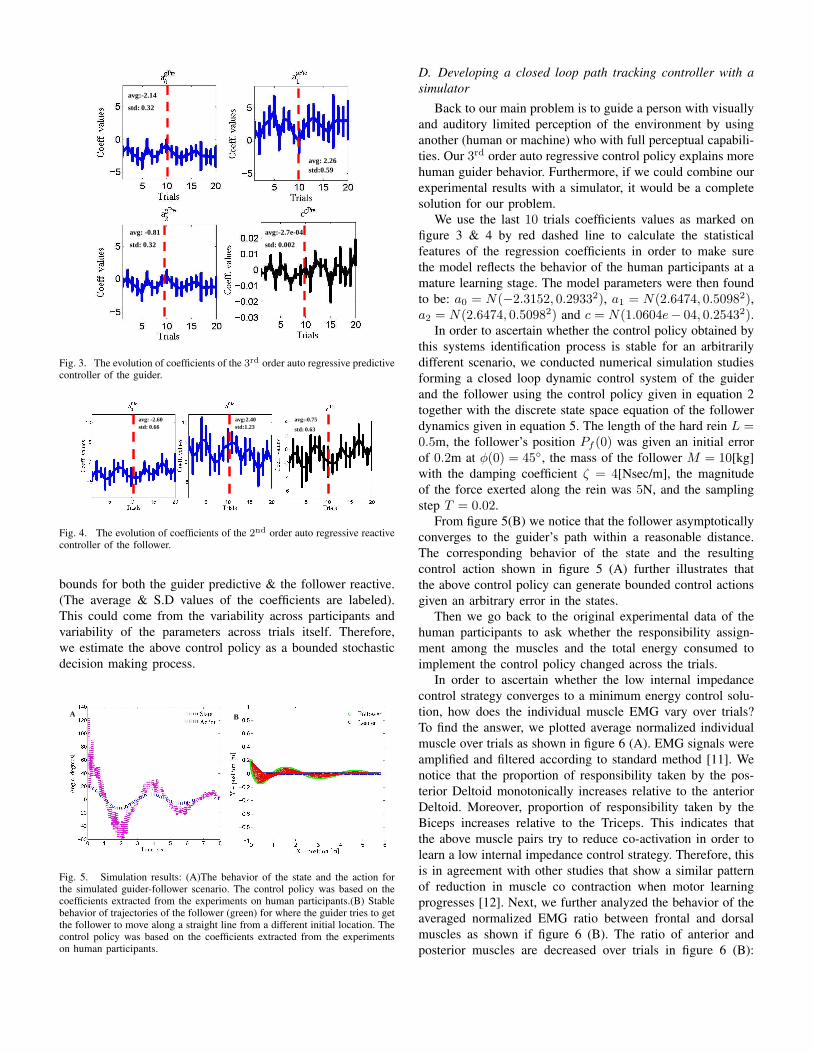
C. Polynomial parameters of a novel linear state dependent
controllers of the duo
Then we move into understand how the polynomial param-
eters of a 3rd & 2nd order linear state dependent controllers
would evolve across learning trials in equation 2 & 3 for the
guider & the follower respectively. We notice in figure 3 & 4
that the history of the polynomial coefficients fluctuates within
avg:-2.14
std: 0.32
avg: 2.26 std:0.59
avg: -0.81
std: 0.32
avg:-2.7e-04
std: 0.002
Fig. 3. The evolution of coefficients of the 3rd order auto regressive predictivecontroller of the guider.
avg: -2.60 std: 0.66
avg:2.40 std:1.23
avg:-0.75
std: 0.63
Fig. 4. The evolution of coefficients of the 2nd order auto regressive reactivecontroller of the follower.
bounds for both the guider predictive & the follower reactive.
(The average & S.D values of the coefficients are labeled).
This could come from the variability across participants and
variability of the parameters across trials itself. Therefore,
we estimate the above control policy as a bounded stochastic
decision making process.
A B
Fig. 5. Simulation results: (A)The behavior of the state and the action forthe simulated guider-follower scenario. The control policy was based on thecoefficients extracted from the experiments on human participants.(B) Stablebehavior of trajectories of the follower (green) for where the guider tries to getthe follower to move along a straight line from a different initial location. Thecontrol policy was based on the coefficients extracted from the experimentson human participants.
D. Developing a closed loop path tracking controller with a
simulator
Back to our main problem is to guide a person with visually
and auditory limited perception of the environment by using
another (human or machine) who with full perceptual capabili-
ties. Our 3rd order auto regressive control policy explains more
human guider behavior. Furthermore, if we could combine our
experimental results with a simulator, it would be a complete
solution for our problem.
We use the last 10 trials coefficients values as marked on
figure 3 & 4 by red dashed line to calculate the statistical
features of the regression coefficients in order to make sure
the model reflects the behavior of the human participants at a
mature learning stage. The model parameters were then found
to be: a0 = N(−2.3152, 0.29332), a1 = N(2.6474, 0.50982),a2 = N(2.6474, 0.50982) and c = N(1.0604e− 04, 0.25432).
In order to ascertain whether the control policy obtained by
this systems identification process is stable for an arbitrarily
different scenario, we conducted numerical simulation studies
forming a closed loop dynamic control system of the guider
and the follower using the control policy given in equation 2
together with the discrete state space equation of the follower
dynamics given in equation 5. The length of the hard rein L =0.5m, the follower’s position Pf (0) was given an initial error
of 0.2m at φ(0) = 45◦, the mass of the follower M = 10[kg]
with the damping coefficient ζ = 4[Nsec/m], the magnitude
of the force exerted along the rein was 5N, and the sampling
step T = 0.02.
From figure 5(B) we notice that the follower asymptotically
converges to the guider’s path within a reasonable distance.
The corresponding behavior of the state and the resulting
control action shown in figure 5 (A) further illustrates that
the above control policy can generate bounded control actions
given an arbitrary error in the states.
Then we go back to the original experimental data of the
human participants to ask whether the responsibility assign-
ment among the muscles and the total energy consumed to
implement the control policy changed across the trials.
In order to ascertain whether the low internal impedance
control strategy converges to a minimum energy control solu-
tion, how does the individual muscle EMG vary over trials?
To find the answer, we plotted average normalized individual
muscle over trials as shown in figure 6 (A). EMG signals were
amplified and filtered according to standard method [11]. We
notice that the proportion of responsibility taken by the pos-
terior Deltoid monotonically increases relative to the anterior
Deltoid. Moreover, proportion of responsibility taken by the
Biceps increases relative to the Triceps. This indicates that
the above muscle pairs try to reduce co-activation in order to
learn a low internal impedance control strategy. Therefore, this
is in agreement with other studies that show a similar pattern
of reduction in muscle co contraction when motor learning
progresses [12]. Next, we further analyzed the behavior of the
averaged normalized EMG ratio between frontal and dorsal
muscles as shown if figure 6 (B). The ratio of anterior and
posterior muscles are decreased over trials in figure 6 (B):
A.
B.
C
M1:
M2:
M2:
Fig. 6. The behavior of the average normalized muscle EMGs: (A)Averagenormalized muscle EMG anterior Deltoid, posterior Deltoids, Biceps, andTriceps.(B) Frontal and dorsal muscle ratio: M1- Biceps triceps muscle ratio,M2- anterior Deltoid posterior Deltoid muscle ratio. (C) The behavior of thiscost indicator J of the 2nd order best fit curve for average EMGs of all fourmuscles of the eight subjects across trials.
M1 while ratio of Biceps and Triceps is increased in figure
6 (B): M2. This suggests that, the priority muscle activation
is taken by frontal and dorsal muscle of Deltoid than Biceps
Triceps pair while the guiding agent produces movements in
horizontal plane swing, anterior and posterior Deltoid pair
is more activated to generate the tug forces along the hard
rein. Alternatively, to compute the average EMG for all four
muscles of all eight participants that reflects the average energy
consumed in a trial given by J =√
∑4i=1
∑SN
j=1 EMG2ij ,
where SN is the number of subjects, EMGij is the average
rectified EMG of the ith muscle of the jth participant (guiding
agent). The behavior of this cost indicator J is shown in figure
6 (C). We can clearly observe from the 2nd order best fit
curve that J starting from lower- mid way of the training
trials increase to a maximum - decreases in last 10 trials -
reaches to minimum values at the last trial. This suggests that
optimization is a non-monotonic process. During the first trials,
it may have given priority to order selection than optimization
in the actuation space, which is also reflected in the behavior
of R2 values in figure 2. Once the optimal order is selected,
subjects exhibit monotonic optimization in the actuation space
as seen in the last 10 trials of figure 6(C), with a corresponding
increase of R2 values in figure 2.
V. CONCLUSION AND FUTURE WORKS
This study was conducted to understand how two human
participants interact with each other using haptic signals
through a hard rein to achieve a path tracking goal when
one partner (the follower) is blindfolded, while the other (the
guider) gets full state feedback of the follower. We found that
1) the control policy of the guider & the follower can be
approximated by a 3rd & 2nd order auto-regressive models re-
spectively, 2) while the guider develops a predictive controller,
the follower gradually develops reactive controllers across
learning trials. The cost functions that are minimized by the
duo, during learning to track a path, we found that the guider
gradually progresses from an initial muscle co-contraction
based command generation strategy to a low energy policy
with minimum muscle co-contraction[13].
In addition to applications in robotic guidance of a person in
a low visibility environment, our findings shed light on human-
robot interaction applications in other areas like robot-assisted
minimally invasive surgery (RMIS). Surgical tele-manipulation
robot could use better predictive algorithms to estimate the
parameters of remote environment for the surgeon with more
accurate adaption of control parameters by constructing inter-
nal models of interaction dynamics between tools and tissues
in order to improve clinical outcomes.
ACKNOWLEDGEMENT
The authors would like to thank UK Engineering and
Physical Sciences Research Council (EPSRC) grant no.
EP/I028765/1, and the Guy’s and St Thomas’ Charity grant
on developing clinician-scientific interfaces in robotic assisted
surgery: translating technical innovation into improved clinical
care (grant no. R090705).
REFERENCES
[1] J. Penders et al. , ”A robot swarm assisting a human firefighter”, Advanced
Robotics, vol 25, pp.93-117, 2011.[2] J. R. Marston et al, ”Nonvisual route following with guidance from
a simple haptic or auditory display”, Journal of Visual Impairment &
Blindness, vol.101(4), pp.203-211, 2007.[3] A. A.Melvin et al, ”ROVI: a robot for visually impaired for collision-
free navigation ”,Proc. of the International Conference on Man-Machine
Systems (ICoMMS 2009), pp. 3B5-1-3B5-6, 2009.[4] J. M. Loomis et al, ”Navigation system for the blind: Auditory Display
Modes and Guidance”, IEEE Transaction on Biomedical Engineering,vol.7, pp. 163 - 203, 1998.
[5] I. Ulrich and J. Borenstein, ”‘The GuideCane-applying mobile robot tech-nologies to assist the visually impaired ”,Systems, Man and Cybernetics,
Part A: Systems and Humans, IEEE Transactions, vol. 31, pp. 131 - 136,2001.
[6] K. B. Reed et al ”Haptic cooperation between people, and between peopleand machines”, IEEE/RSJ Int. Conf. on Intelligent Robots and Systems
(RSJ), vol. 3, pp. 2109-2114, 2006.[7] K. B. Reed et al, ”Replicating Human-Human Physical Interaction”, IEEE
International Conf. on Robotics and Automation (ICRA), vol.10, pp. 3615- 3620, 2007.
[8] D. Feygin et al, ”Haptic Guidance:Experimental Evaluation of a HapticTraining Method for a perceptual Motor Skill”, Proc. of the 10th symp.
on haptic interferences for Virtual Enviornment and Teleoperator sys-
tems(HAPTICS 2002), pp. 40 - 47, 2002.[9] K. B. Reed et al ”‘Haptic cooperation between people, and between people
and machines”’, In IEEE/RSJ Int. Conf. on Intelligent Robots and Systems,pp. 2109-2114, 2006.
[10] Flanders.M, ”Choosing a wavelet for single-trial EMG” ,Journal of
Neuroscience Methods, vol.116.2, pp.165-177, 2002.[11] Flanders et al, ”Basic features of phasic activation for reaching in vertical
planes”,Experimental Brain Research, vol.110, pp. 67-79, 1996.[12] D.W. Franklin et al. ”Adaptation to stable and unstable dynamics
achieved by combined impedance control and inverse dynamics model”,Journal of neurophysiology,vol.90, pp. 3270-3282,2003.
[13] K.A. Thoroughman and S. Reza. ”Learning of action through adaptivecombination of motor primitives” ,Nature, vol.407, pp. 742-747,2000.