Decreasing Supplies of Conventional Water & Energy Resources.
Sustainable Management of Water & Energy Resources
• Eight Major Water Using IndustriesOil & GasRefining & PetrochemicalsPower GenerationFood and BeveragePharmaceuticalMicroelectronics Pulp & Paper, and Mining
GWI: Industrial Desalination & Water Reuse: Ultrapure water, challenging waste streams and improved efficiency,
3
Strategies: Water Conservation / Water Use EfficiencyUnaccounted / Water LossesWater RecyclingDesalination - Most Energy Intensive / Expensive Water?
4
5
• DesalinationAn Energy Intensive Process,An Integral Part of the Future Water Supply PortfolioSource Waters – Generally Four Types
Brackish Ground Water, Surface Water, Municipal WW, Agricultural Runoff, Industrial Effluents, Sea Water, etc.
Main Processes Categories:Thermal 4 - 6 kWh / m3 + SteamHeating of Contaminated Water under Vacuum Conditions to Create Pure Water Vapors)
Membranes 1 - 6 kWh / m3
Energy Requirements - Function of:Plant Capacity, Feed Water Quality, Pretreatment, Desalination Process/Technology, and Level of Treatment
Desalination Technology of Most Interest TodayReverse Osmosis
In Early Days of Membrane Desalination, Energy Use was in the Order of: 20 kWh / m3
ADC Accomplished: 1.62 kWh / m3
6.4 kWh / 1,000 gal2,100 kWh / AF
This Additional Energy Demand is due to Factors like:
Inefficiency of Feed Pump and Motor,Water Permeating through Membranes (Membrane Resistance),Energy Lost with Brine,Recovery (Salinity & Temp. Impacts),Membrane System Configuration,Design Flux, & Pretreatment, etc.
11
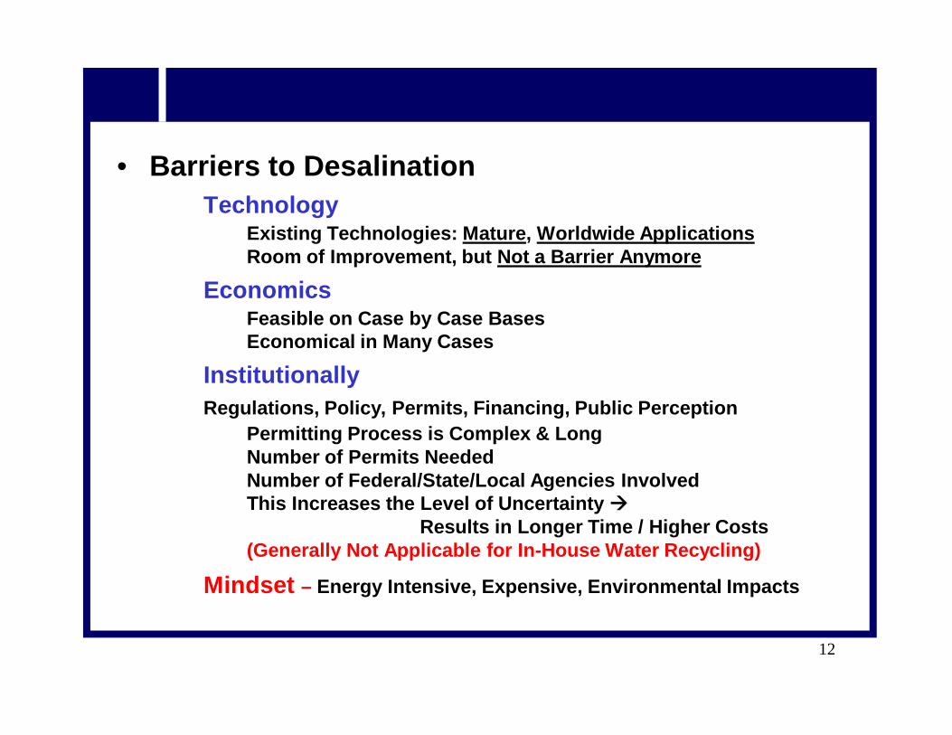
• Barriers to DesalinationTechnology
Existing Technologies: Mature, Worldwide ApplicationsRoom of Improvement, but Not a Barrier Anymore
EconomicsFeasible on Case by Case Bases Economical in Many Cases
Institutionally Regulations, Policy, Permits, Financing, Public Perception
Permitting Process is Complex & Long Number of Permits NeededNumber of Federal/State/Local Agencies InvolvedThis Increases the Level of Uncertainty
Results in Longer Time / Higher Costs(Generally Not Applicable for In-House Water Recycling)
Mindset – Energy Intensive, Expensive, Environmental Impacts
12
• Desalination Plants Global Installed Capacity*
78.4 million m³/d today,71.9 million in 2011; & 65.1 million in 2010Approx. 60% Capacity Treats Seawater; Remainder Treats Brackish Water
Largest Membrane Desalination PlantVictoria Desalination Plant in Melbourne: 444,000 m³/d (Came on line in Aug. 2012)
Work in Progress on:Magata Plant (500,000 m³/d) in AlgeriaSoreg Plant (510,000 m³/d) in Israel.
USA Largest SW Plant (189,000 m³/d @ Carlsbad) – Work in Progress (Finally). Estimated Price of Water: $1.65 – 1.86 / m3
2 New 758 MW NG-CC Power Plants in TexasSource Water: Treated WW & Lake Water, Respectively450 gal/min Treatment Capacity for Each Plant98% Water will be RecycledTechnologies:
i. Brine Concentrator & ZLD Crystallizerii. Brine Concentrator
Steel Mill in IndiaMain Component - EDR
GE Press Release: Jan. 15, 2013; April 26, 2012
16
• Solution ProvidersA Few Examples:
Aquatech InternationalGESiemens IndustryVeloia Water Solutions & TechnologiesEco-Tech Inc.Severn Trent Services, Inc.DNV KEMA Energy & SustainabilityH2O Innovation
17
• Other Desalination Technologies of Interest
18
• Forward Osmosis A Natural Process for Water Transfer through a Selectively Permeable Membrane Driven by the Osmotic Pressure Gradient Across the Membrane. Since, it is Driven by an Osmotic Pressure Gradient, FO Does Not Require Significant Energy Input (only for Stirring or Pumping of Solutions).FO Membranes Reject Organics, Minerals and Other Solids -Similar to Traditional Pressure Driven RO; but Resist Typical Fouling Problems.
Technical Barriers in Forward Osmosis:Lack of an Ideal Draw Solution that Exhibits High Osmotic Pressure & can be Easily Regenerated to Produce Pure WaterLack of an Optimized Membrane to Produce a High Water Flux, Comparable to Commercial RO MembranesA Suitable Module Design to Maintain Long-Term System Performance for Specific Applications.
19
20
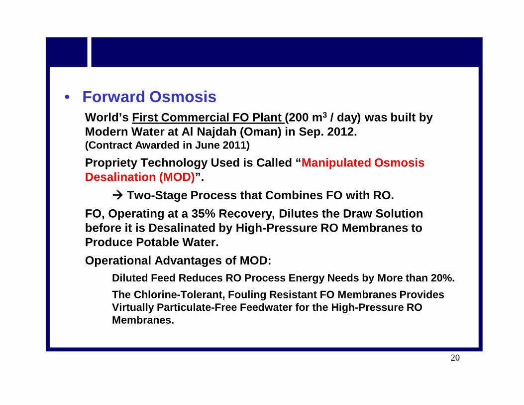
• Forward Osmosis World’s First Commercial FO Plant (200 m3 / day) was built by Modern Water at Al Najdah (Oman) in Sep. 2012. (Contract Awarded in June 2011)Propriety Technology Used is Called “Manipulated Osmosis Desalination (MOD)”.
Two-Stage Process that Combines FO with RO.FO, Operating at a 35% Recovery, Dilutes the Draw Solution before it is Desalinated by High-Pressure RO Membranes to Produce Potable Water.Operational Advantages of MOD:
Diluted Feed Reduces RO Process Energy Needs by More than 20%.The Chlorine-Tolerant, Fouling Resistant FO Membranes Provides Virtually Particulate-Free Feedwater for the High-Pressure RO Membranes.
• FO Concept
21
MOD Concept
Concentrate
Permeate
DilutedOsmotic Agent
ConcentratedOsmotic Agent
FO Membrane
RO Membrane
Feed Water
• Membrane DistillationApparently More Promising for Industrial Applications where Free Waste Heat is Available Combining Membrane Technology & Evaporation Processing in One Unit,Needs Both Thermal & Electrical Energy,Water Vapors are Transported through the Hydrophobic Membrane Pores via the Temperature Gradient across the Membrane, Offers the Attractiveness of Operation at Atmosphere Pressure and Low Temperatures (30o – 90oC),Has the Theoretical Ability to Achieve 100% Salt Rejection.Promising and Cost Competitive with RO where Thermal Energy (Heat) is Available at Low or No Cost.
22
• Membrane Distillation Schematic
23
Courtesy Aquaver (The Netherlands)
• Membrane Distillation Schematic with Four Stages
24
Courtesy Aquaver (The Netherlands)
• Geothermal DesalinationRD&D StageFirst Proof of Concept: 2001
From 2005 to 2009, Testing with 6th Prototype at Scripps Institute of Oceanography Demonstrated Salt Reduction in Seawater from 35,000 ppm to 51 ppm.Claimed Benefits include:
Relatively Environmental Friendly Geothermal Energy, & Less Maintenance than RO Membranes
25
• Nano-DesalinationNanotube Membranes are Arrangedand Packed like a Pile of Straws;Water Molecules can Pass through Membranes, while Bacteria, Biological Material and Other Impurities can Not.
• Thermo-Ionic Desalination ProcessProprietary Technology (Saltwork) –Employs an Innovative Thermo-IonicEnergy Conversion System. The Energy Reduction is Achievedby Harnessing Low-Temperature Heat and Atmospheric Dryness toOvercome Desalination EnergyBarrier;The System Works Best in Dry Regions.
26
• Low Temperature Thermal DesalinationInvolves Flashing Relatively Warm SW (28o – 30oC) Inside a Vacuum FlashChamber and Condensing the Resultant Vapor using Deep Sea Cold Water (7o – 15oC);Technology Was Developed in Italy, but First LTTD Plant was Built in India; The Process can be Used to ProduceDrinking Water as well as for PowerGeneration and Air-Conditioning.
• Passarell Process Combines Accelerated Distillation with Advance Vapor CompressionSystem (AD-AVCS) Resulting in Process Efficiency and Economywhich is Unobtainable from OtherDesalination Technologies.
27
• Capacitive Deionization (CDI)(aka Flow Through Capacitor - FTC)Works by Adsorption of Ions in theElectric Double Layer of PorousCarbon Electrodes;Accordingly, the FTC RemovesMinerals & Salts from AqueousSolutions by Charging Electrodes.
• Hybrid ConfigurationsHybrid Desalination Systems Combine Thermal and MembraneDesalination Processes;Power / Membrane / Thermal Configurations are Characterized:
More Operationally Flexible, Less Specific Energy Consumption,Low Construction Cost, High Plant Availability, and Better Power and Water Matching.
28
• Solar DesalinationDesalination Using Solar Power
• Geothermal DesalinationDesalination Using Geothermal Heat
29
Solar Desalination
Geothermal Desalination
30
• SummaryDesalination May be Relatively Expensive for Municipal Water Supplies, but Makes Lot More Sense for Industrial Sector;Thermal Desalination & Emerging Technologies like Membrane Distillation Appears to be More Attractive to Recycle Strong Industrial Wastewaters;Industrial WW Recycling Helps Making Water & Energy Resources Sustainable; Reduces Carbon Footprint; and Demonstrates Corporate Social Responsibility (CSR).