1 1 John H. Scott NASA/JSC/EP3 Houston TX 77058 USA, (281) 483-3136, [email protected]25 June 2007 An Overview of Space Power Systems for NASA Missions John H. Scott, Presenter Chief, Energy Conversion Branch NASA Lyndon B. Johnson Space Center/EP3 Houston, TX 77058 USA 281.483.3136 [email protected]Valerie J. Lyons Chief, Power and In Space Propulsion Division NASA Glenn Research Center/RP Cleveland, OH 44135 USA 216.433.5970 [email protected]My task is to provide an overview of spacecraft power systems: •Programmatic trends •Power system tradespace •State-of-the-art •Development directions https://ntrs.nasa.gov/search.jsp?R=20070020422 2018-05-29T11:37:31+00:00Z
Transcript
1
1
John H. Scott NASA/JSC/EP3 Houston TX 77058 USA, (281) 483-3136, [email protected] 25 June 2007
An Overview of Space Power Systems for NASA Missions
John H. Scott, PresenterChief, Energy Conversion BranchNASA Lyndon B. Johnson Space Center/EP3Houston, TX 77058 [email protected]
Valerie J. LyonsChief, Power and In Space Propulsion DivisionNASA Glenn Research Center/RPCleveland, OH 44135 [email protected]
My task is to provide an overview of spacecraft power systems:
•Programmatic trends•Power system tradespace•State-of-the-art•Development directions
John H. Scott NASA/JSC/EP3 Houston TX 77058 USA, (281) 483-3136, [email protected] 25 June 2007
NASA Power Needs• Power is a critical commodity for all engineering efforts and is
especially challenging in the aerospace field. There are important challenges to NASA missions in aerospace power – including generation, energy conversion, distribution, and storage. NASA’s newest vehicles will have power systems based on current technology, but will have the challenges of being light-weight, energy-efficient, and space-qualified. Future lunar and Mars “outposts” will need high power generation units for life support and energy-intensive exploration efforts.
• Basic systems engineering trades are conducted for crewed spacecraft. Trades for such applications are conducted with priorities that are quite different from those of more general applications. Solutions have been chosen via this process for crewed spacecraft in power generation, energy storage, electric power distribution and control (EPD&C), and actuation of thrust vectors and aerodynamic (aero) surfaces.
3
3
John H. Scott NASA/JSC/EP3 Houston TX 77058 USA, (281) 483-3136, [email protected] 25 June 2007
Lunar Heavy Launch DevelopmentLunar Heavy Launch Development
Earth Departure Stage DevelopmentEarth Departure Stage Development
7th Human Lunar Landing
7th Human Lunar Landing
Space ShuttleSpace Shuttle
Robotic PrecursorsRobotic Precursors
Lunar Outpost Buildup
Mars Development
Lunar Lander DevelopmentLunar Lander Development
Surface Systems DevelopmentSurface Systems Development
Commercial Crew/Cargo for ISSCommercial Crew/Cargo for ISSCommercial Crew/Cargo for ISS
CEV DevelopmentCEV Development
Crew Launch DevelopmentCrew Launch Development
4
4
John H. Scott NASA/JSC/EP3 Houston TX 77058 USA, (281) 483-3136, [email protected] 25 June 2007
• Meet all U.S. human spaceflight goals• U.S. system capable of servicing the International Space Station• Significant advancement over Apollo
– Double the number of crew to lunar surface– Four times number of lunar surface crew-hours– Global lunar surface access with anytime return to the Earth– Enables a permanent human presence while preparing for Mars
and beyond– Can make use of lunar resources– Significantly safer and more reliable
• Minimum of two lunar missions per year• Provides a 125 metric ton launch vehicle for lunar and later Mars missions and beyond• Higher ascent crew safety than the Space Shuttle• Orderly transition of the Space Shuttle workforce• Requirements-driven technology program
Safe, Accelerated, Affordable and Sustainable Approach
5
5
John H. Scott NASA/JSC/EP3 Houston TX 77058 USA, (281) 483-3136, [email protected] 25 June 2007
Exploration Technology Development Program’s Power-related Projects
• Energy Storage project - Advanced lithium-ion batteries and regenerative fuel cells for energy storage are being developed. These technologies will enable a solar power system to store energy for use by the outpost during the lunar night, and they will provide power to mobile systems such as EVA suits and rovers.
• Fission Surface Power Systems project - Developing concepts and technologies for affordable nuclear fission surface power systems for long duration stays on the Moon and exploration of Mars. NASA iscollaborating with the Department of Energy (DOE) on developmentof fission surface power system concepts.
• Thermal Control project - Developing heat pumps, evaporators, and radiators for thermal control of the Orion and lunar surface systems such as habitats, power systems, and EVA suits.
• Crew Support and Accommodation - Component technologies for an advanced Extra-Vehicular Activity (EVA) suit are under development. The current spacesuit used on the Shuttle and ISS cannot be used for walking on the Moon due to limited mobility and highmass. These component technologies for EVA include life support,thermal control, energy storage, and dust mitigation. In-situ resource utilization will require significant power provision and providereactants for fuel cells.
In 2005, NASA conducted the Exploration Systems Architecture Study (ESAS) to define the initial lunar exploration architecture, and to identify key technology needs. The ETDP consists of 12 projects that are formulated to address the high priority technology needs for lunar exploration identified by the ESAS. The projects are: Structures, Materials, and Mechanisms, Protection Systems, Propulsion and Cryogenics, Avionics and Software, In-Situ Resource Utilization, Robotics, Operations, and Supportability, Environmental Control and Life Support, Energy Storage, Fission Surface Power Systems, Thermal Control, and Crew Support and Accommodation, and International Space Station (ISS) Research and Operations. Several of these projects have power and energy systems as key elements. In energy storage, advanced lithium-ion batteries and regenerative fuel cells (Figure 1) for energy storage are being developed. These technologies will enable a solar power system to store energy for use by the outpost during the lunar night, and they will provide power to mobile systems such as EVA suits and rovers. The Fission Surface Power Systems project is developing concepts and technologies for affordable nuclear fission surface power systems for long duration stays on the Moon and exploration of Mars. NASA is collaborating with the Department of Energy (DOE) on development of fission surface power system concepts. The Thermal Control project is developing heat pumps, evaporators, and radiators for thermal control of the Orion and lunar surface systems such as habitats, power systems, and EVA suits. For Crew Support and Accommodation, component technologies for an advanced Extra-Vehicular Activity (EVA) suit are under development. The current spacesuit used on the Shuttle and ISS cannot be used for walking on the Moon due to limited mobility and high mass. These component technologies for EVA include life support, thermal control, energy storage, and dust mitigation. In-situ resource utilization will require significant power provision and provide reactants for fuel cells.
6
6
John H. Scott NASA/JSC/EP3 Houston TX 77058 USA, (281) 483-3136, [email protected] 25 June 2007
• Solar power generation plays an important supporting role for some of their Roadmap “Flagship” missions and is even more important for missions in the New Frontiers and Discovery Programs. To effectively use solar arrays farther from the Sun, specific power improvements are needed to enable more power per kilogram of solar array and in Low Intensity Low Temperature (LILT) technology. NASA is currently planning a New Millennium space validation experiment that is seeking to validate arrays with performance of 175 W/kg, double the current state–of–practice.
• Energy storage technology was critical to the success of robotic exploration missions such as the Mars Exploration Rovers. In that mission, improvements of almost a factor of two in specific power and a factor of four in specific volume made it possible to pack a significant and successful science payload. Performance improvements in rechargeable batteries are still needed for operations at both high and low temperatures.
Power is also a critical technology for the proposed missions of NASA’s Science Mission Directorate.
7
7
John H. Scott NASA/JSC/EP3 Houston TX 77058 USA, (281) 483-3136, [email protected] 25 June 2007
Science Mission Directorate’s Power Needs
• Science Mission Directorate Flagship missions are to destinations where, due to extreme operating environments, nuclear power may be required for electrical power production and thermal management.– Venus Mobile Explorer mission, Advanced Stirling Radioisotope
Generator (ASRG) would produce increased specific power for space missions and can be used to cool the electronics as well as produce power.
– Europa Explorer (EE) and Mars missions - NASA and DoE are currently developing a Multi–Mission Radioisotope Thermoelectric Generator (MMRTG), capable of operating in space or in an atmospheric environment. This dual–purpose system will enable more flexibility in power requirements to support missions with lower power needs. The power of each MMRTG unit is about 100 watts electric.
– Titan Explorer mission, MMRTG’s could be used if small modifications were made to its heat–rejection system.
Stirling GeneratorMMRTG
8
8
John H. Scott NASA/JSC/EP3 Houston TX 77058 USA, (281) 483-3136, [email protected] 25 June 2007
Elements of Spacecraft Power Systems
help
•Power Systems Engineering Trade Space
•Power Generation and Energy Storage
•Power Distribution and Control
•Actuation
I’ll now discuss:•How basic systems engineering trades to meet the program requirements I just mentioned are conducted for manned spacecraft with priorities that are quite different from those of more general applications•Solutions chosen via this process for manned spacecraft in
•Power generation & energy storage•EPD&C•Actuation (thrust vector and control surfaces), including hydraulic and electromechanical actuation
9
9
John H. Scott NASA/JSC/EP3 Houston TX 77058 USA, (281) 483-3136, [email protected] 25 June 2007
Trade Space for Electric Power Systems
Commercial/Military Electric Power Systems:
• Development, Production & Operation Cost ($/kW)
• Specific Power/Energy (kW/kg, kWh/kg)
• Emissions (NOx, COx, noise)
Constraint: Public Safety
There are common considerations for the design of a power system for any application, with only a variation in priority.•All elements of Cost•Power and energy densities•Emissions (pollutants, greenhouse gases, noise)
All must be optimized within a hard constraint of safe operability in the field.
10
10
John H. Scott NASA/JSC/EP3 Houston TX 77058 USA, (281) 483-3136, [email protected] 25 June 2007
• Specific Power/Energy (kW/kg; kWh/kg)
Spacecraft Electric Power Systems:
• Specific Power/Energy (kW/kg; kWh/kg)
Constraint: Mission Reliability/Durability
• Specific Power/Energy (kW/kg; kWh/kg)
Trade Space for Electric Power Systems
Override: Development Cost ($MM)
For spacecraft to date, things have been like with real estate……
With launch costs hovering at $20K/kg, specific power and energy has overwhelmed almost any other consideration
•NASA has stuck to this rule, but has begun to sometimes run up against exceptions (which we’ll discuss)
The absolute constraints is not public safety but mission reliability, almost always judged by having verifiable redundancy, and sufficient durability, which, with the advent of the long missions planned for Exploration Initiative, is becoming a much more challenging issue. In general redundancy trumps weight in importance.
That is: TWO FAULT TOLERANT TO CATASTROPHIC FAILURE = AT LEAST THREE INDEPENDENT POWER STRINGS….when this doesn’t end up decreasing relabilty. Redundancy management is crucial and complicated.PRA calculations are only a minor input to design decisions, as database is too small. PRA’s are used in operational decisions.
We will push mass reduction and redundancy until we hit the overriding constraint of development cost…and we sometimes hit that before we thought we would. Note thatrecurring production and even operational costs are not primary considerations. We don’t fly enough.
11
11
John H. Scott NASA/JSC/EP3 Houston TX 77058 USA, (281) 483-3136, [email protected] 25 June 2007
Power Generation and Energy Storage
Photovoltaics Direct Chemical Conversion
•Batteries•Fuel Cells
Nuclear •Decay•Fission
For power generation and energy storage, we’ll discuss three technologies.•Solar sources (photovoltaics for direct electric generation)•Direct chemical conversion (primary batteries and fuel cells for generation only and secondary batteries and regenerative fuel cells for storage of energy from other generation sources)•Nuclear sources (radioactive decay with Pu and atomic fission) with heat engine conversion
12
12
John H. Scott NASA/JSC/EP3 Houston TX 77058 USA, (281) 483-3136, [email protected] 25 June 2007
Power Generation and Energy Storage
Primary Power Specific Energy Trade Space
FUEL CELLS
PRIMARYBATTERIES
SOLARARRAYS
RADIOISOTOPICTHERMAL
GENERATORS
NUCLEARREACTORS
ELEC
TRIC
PO
WER
(WA
TTS)
101
102
103
104
105
106
107
1 MINUTE 1 HOUR 1 DAY 1 MONTH 1 YEAR 10 YEARS
USE DURATION
The locus of maximum specific energy solutions for a given powerdemand and mission duration have been plotted on this chart.•Taken from a 1970’s text.•Lines have not and will not move much (except between batteries and fuel cells•Changes have been primarily in the development cost (from industrial state-of-the-art to spaceflight-ready) and perceived development risk of each solution.
13
13
John H. Scott NASA/JSC/EP3 Houston TX 77058 USA, (281) 483-3136, [email protected] 25 June 2007
Trade Space for Electric Power Systems
Manned Spacecraft Power System Selections
xx?
x?
CEV
?Nuclear
?xxPhotovoltaics
?RegenerativeFuel Cell Storage
?xxxPrimary Fuel Cells
?xxxSecondary Battery Storage
?xxPrimary Batteries
FutureX-38ISSShuttleSkylabApolloGeminiMercury
Trades on that chart and judgements of development cost/risk have driven solutions selected for manned spacecraft.•Mercury was a short mission with low power demand. •ISS has nearly indefinite mission length with high power demand.•The constraint Development cost has kept nuclear power from any manned mission so far.
14
14
John H. Scott NASA/JSC/EP3 Houston TX 77058 USA, (281) 483-3136, [email protected] 25 June 2007
Power Generation and Energy Storage
Solar PowerPhotovoltaic arrays
CEV
sunlight
Silicon: η < 10%Gallium Arsenide: η< 15%
pn
Conversion efficiency improvements are focus of much research in nanotechology
Unmanned spacecraft limited to surface-mount or one-time deployable arrays Manned spacecraft capable of
deployable, pointable, and retractable arrays
ISS SAW
0
50
100
150
200
250
0 50 100 150 200 250 300
Volts
Am
ps
Solar Array
Load
ISS Array Operating Points
•Among the power generation options, we’ll first discuss solar power.•Photovoltaics produce power from the photoelectric effect: incident sunlight creates an electric potential between p and n semiconductors that can drive a current.
•Voltage output very sensitive to current draw, so current must be carefully managed ..string-by-string (ISS keeps power at lower point on curve to save current)•Electromagnetic conversion efficiency (defined as a percentage of incident radiation converted) driven by semiconductor materials selected.
•Solar photovoltaics remain solution of choice for near earth power generation•First utilized in 1970s•Much materials research focused on improvements in very low efficiency (nano engineering yielding thin films and quantum dots to capture a wider spectrum, nanotube conductors) NASA and DoD are supporting this research.•Yield linear improvement in surface area and mass
•Concerns with reliability of kinematic chains in the thermal, vacuum, and freefall environment of space limit unmanned spacecraft to surface mount arrays or to one time deployable arrays (with resulting limits on maneuverability)•Availability of astronaut intervention as back-up enables much more efficient arrays on manned spacecraft. Arrays can be retracted to allow energetic mission maneuvers and pointed optimize power generation.
•Note that the ISS arrays’ two-axis pointing and deployment/retraction mechanisms have been utilized three times. We’ve had to send astronauts out to fiddle with it two of those three times.•P6 and P4 are up now. S4 up next in 3/15. S6 (final) planned for 7/08.
15
15
John H. Scott NASA/JSC/EP3 Houston TX 77058 USA, (281) 483-3136, [email protected] 25 June 2007
Power Generation and Energy Storage
Direct Chemical ConversionBatteries and Fuel Cells
Batteries
Cathode-
Anode+
Electrolyte
(ηth up to 90%)
Fuel Cells
Electrolyte
Cathode-
Anode+
H2 O2
(ηth up to 70%)
Primary Power and Secondary Storage
•We’ll now turn to batteries and fuel cells.•Batteries and fuel cells can each be used as either a primary power source or as a secondary energy storage system•Fuel cells have fuel and oxidant fed to or generated from storage tanks•Batteries contain all chemical reactants internally
•Both technologies have been the focus of large commercial investment for electronics, industrial, and transportation applications•NASA has tried to take advantage of this to meet its mission requirements at less of a development cost…with varying degrees of success.
16
16
John H. Scott NASA/JSC/EP3 Houston TX 77058 USA, (281) 483-3136, [email protected] 25 June 2007
Power Generation and Energy Storage
Change in Gibbs Free Energy (ΔG) = ΔH - TΔS = -nFE
Efficiency Limit: ηth < nFE/ΔH = 1 – (TΔS/ΔH)
Ideal Oxidation Potential (Eo) = 1.23 V for H2/O2 fuel cell
= 3.8 V for Li-Ion battery
General Nernst Equation: E = Eo + (RT/nF)ln[cγdδ/aαbβ]
Ideal potential drops with temperature: (δEo/δT)P = ΔS/nF
Ideal potential rises with pressure: (δEo/δP)T = -ΔV/nF
Fuel OxidantAnode
Cathode
Load
+ ion
- ionor
Electrolyte
e-
+ -
Oxidation Reduction
Eo
CellVoltage
(V)
Current Density (A/cm2)
Eo
Polarization Losses
Activation (Reaction Rate Loss)
Ohmic(Resistance Loss)
Concentration(Gas Transport Loss)
CellVoltage
(V)
Efficiency(ηth)
Current Density (A/cm2)
Temperature
Pressure
Overall Efficiency Trends
Direct Chemical Conversion Basics
•I’d like to make a couple of points with the fundamentals of direct conversion:•In direct chemical conversion, a current is driven by the electrochemical potential of a fuel/oxidant pair driving ions through an electrolyte.
•Unlike Carnot heat engine conversion, efficiency limited by ratio between Gibbs Free Energy and Enthalpy released by the reaction rather than by differences in temperature between heat addition and rejection.•Available potential is driven by reactivity (e.g., concentration) of species involved (partial pressure in fuel cells; state of charge in batteries)•The practical performance limitations on both batteries and fuel cells are driven by the shape of the polarization curve, which is in turn driven by reaction kinetics and cell pressure and temperature. •Shape of polarization curve is subject of considerable reserach, especially nanotechnology (nanotubes can reduce effective current density and lower ohmic resistance in electrodes; first effect is primary.).•NASA JSC works with GRC and JPL in this area.
17
17
John H. Scott NASA/JSC/EP3 Houston TX 77058 USA, (281) 483-3136, [email protected] 25 June 2007
There is a lot of commercial interest in fuel cells (automobiles, APUs). Commercial investment in Hydrogen Economy focuses on problems very different from manned program needs. •Minimize expensive catalyst vs. Maximize efficiency (0.4 mg/cm2 vs 25 mg/cm2)•NASA has little concern for manufacturing cost (Shuttle keeps 23plants or parts for plants in inventory; has only bought ~100 stacks over the 30 years of space shuttle)•Manned program needs about the same durability (commercial: 5000 hr auto but 40000 hr fixed; space 10000 hr +) and highest possible thermodynamic efficiency.•Commercial focus on fuel reforming and contaminant compatibility vs. NASA availability of pure reactants (this may change)
•May be common ground in electrolysis for producing oxygen on moon
18
18
John H. Scott NASA/JSC/EP3 Houston TX 77058 USA, (281) 483-3136, [email protected] 25 June 2007
Power Generation and Energy Storage
Direct Chemical ConversionBatteries and Fuel Cells
System Mass
EnergyStored
Batteries
Fuel Cells
•As for the decision on whether to use a fuel cell or a battery, there is a classic specific energy curve (for volume as well). For a 10 kW spacecraft bus demand and a comparison between SOA Li-Polymer batteries and H2/O2 alkaline fuel cells with supercritical storage, lines cross at about 26 hrs.As for a projection of the future, the fuel cell line slope will likely not change much, though dry mass by decrease by ~20%. Li-Ion battery slope (i.e. specific energy) may improve dramatically (almost double..nanoengineering). With this, lines would cross at ~50 hrs.
The shuttle drew 13-15 kW on-orbit during the last mission. Peak of 21kW during ascent.
19
19
John H. Scott NASA/JSC/EP3 Houston TX 77058 USA, (281) 483-3136, [email protected] 25 June 2007
Power Generation and Energy Storage
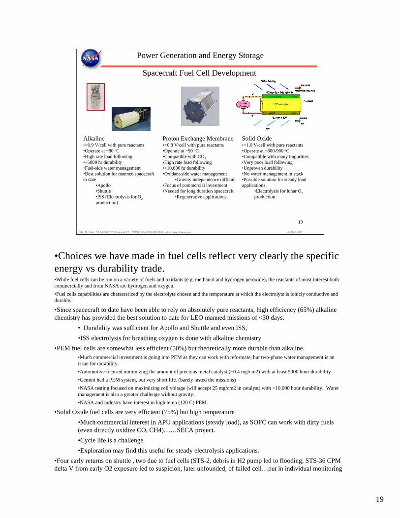
Spacecraft Fuel Cell Development
Alkaline•>0.9 V/cell with pure reactants•Operate at ~80 oC•High rate load following•~5000 hr durability•Fuel-side water management•Best solution for manned spacecraft to date
•Apollo•Shuttle•ISS (Electrolysis for O2production)
Proton Exchange Membrane•>0.8 V/cell with pure reactants•Operate at ~90 oC•Compatible with CO2•High rate load following•>10,000 hr durability•Oxidant-side water management
•Gravity independence difficult•Focus of commercial investment•Needed for long duration spacecraft
•Regenerative applications
Solid Oxide•>1.0 V/cell with pure reactants•Operate at ~800-900 oC•Compatible with many impurities•Very poor load following•Unproven durability•No water management in stack•Possible solution for steady load applications
•Electrolysis for lunar O2production
•Choices we have made in fuel cells reflect very clearly the specific energy vs durability trade.•While fuel cells can be run on a variety of fuels and oxidants (e.g, methanol and hydrogen peroxide), the reactants of most interest both commercially and from NASA are hydrogen and oxygen.•Fuel cells capabilities are characterized by the electrolyte chosen and the temperature at which the electrolyte is ionicly conductive and durable..
•Since spacecraft to date have been able to rely on absolutely pure reactants, high efficiency (65%) alkaline chemistry has provided the best solution to date for LEO manned missions of <30 days.
• Durability was sufficient for Apollo and Shuttle and even ISS,•ISS electrolysis for breathing oxygen is done with alkaline chemistry
•PEM fuel cells are somewhat less efficient (50%) but theoretically more durable than alkaline.•Much commercial investment is going into PEM as they can work with reformate, but two-phase water management is an issue for durability.•Automotive focused minimizing the amount of precious metal catalyst (~0.4 mg/cm2) with at least 5000 hour durability•Gemini had a PEM system, but very short life. (barely lasted the missions)•NASA testing focused on maximizing cell voltage (will accept 25 mg/cm2 in catalyst) with >10,000 hour durability. Water management is also a greater challenge without gravity.•NASA and industry have interest in high temp (120 C) PEM.
•Solid Oxide fuel cells are very efficient (75%) but high temperature•Much commercial interest in APU applications (steady load), as SOFC can work with dirty fuels (even directly oxidize CO, CH4)……SECA project.•Cycle life is a challenge•Exploration may find this useful for steady electrolysis applications.
•Four early returns on shuttle , two due to fuel cells (STS-2, debris in H2 pump led to flooding; STS-36 CPM delta V from early O2 exposure led to suspicion, later unfounded, of failed cell…put in individual monitoring
20
20
John H. Scott NASA/JSC/EP3 Houston TX 77058 USA, (281) 483-3136, [email protected] 25 June 2007
Power Generation and Energy Storage
Secondary Battery Energy Storage
X-38
Shuttle Electric APU
ISS
EMU
•In batteries NASA requirements not as different from commercial as with fuel cells
•NASA has much less concern for recurring cost•ISS Ni-H battery is expensive•NASA has more extreme durabilty/reliability requirements
•Good results have been obtained in applying commercially developed battery CELL technology to manned space applications.
•Four programs provide examples:•ISS•Space Shuttle Electrohydraulic pump upgrade study (not flown we’ll discuss later)•EMU upgrades•X-38 (prototype crew escape vehicle for ISS-not flown)
21
21
John H. Scott NASA/JSC/EP3 Houston TX 77058 USA, (281) 483-3136, [email protected] 25 June 2007
Power Generation and Energy Storage
Secondary Battery Energy Storage
X-38 Project selected different battery chemistries per rate requirements
NiMH for 28 V housekeeping•Deliver 10.8 kWh•32 Wh/kg•C/3 steady discharge rate•C/8 charge rate•In-cabin environment
Ni-Cd for 260 V actuation•Deliver 4.1 kWh; 104 kW max power•16 Wh/kg• Discharge rates ramp from 1 C to 10 C•Trickle charge maintenance•Space vacuum environment
•The use of commercial grade cells was pioneered with our work onthe X-38 project’s secondary batteries (1999).•Secondary batteries selected to allow for top off after checkouts on-orbit•Rate capability at best specific energy drove chemistry selection. (Li-Ions not really understood yet)•X-38 program developed concept of custom aerospace batteries built up from small, lot screened, commercially manufactured cells.
•Greatly reduced development cost•Minor hit in specific energy
22
22
John H. Scott NASA/JSC/EP3 Houston TX 77058 USA, (281) 483-3136, [email protected] 25 June 2007
Power Generation and Energy Storage
Secondary Battery Energy StorageShuttle “Electric APU” studied as path to relieve hazardous turnaround operations•Weight increase of 2000 lbs accepted!
“Large Cell”82S
“Small Cell”82S-88P
Li-Ion chemistry selected for mass, life, and rate ability•28kWh @ ~80 Wh/kg; 130 kW peak power, discharge at C/2•230-360 VDC •Two design solutions competed on cost
HydraulicPumpMotorInverter
Control Unit
LOAD
Water PumpsFor Inverter Cooling
InverterControl Unit
HydraulicPumpMotor
COOLING SYSTEM
Water Tank
Boiler HX
Ground Power
CASE DRAIN
Battery
•With the Electric APU project, we also considered the use of commerical vs. custom aerospace cells.•The EAPU project was an exception to the specific energy priority: 2000 lb vehicle weight penalty was to be paid to ease ground operations and eliminate some failure modes with hydrazine.•EAPU project developed to replace hydrazine gas turbine-driven hydraulic pumps) with battery-fed electric hydraulic pumps (33 gpm max each).•Shuttle Program invested in EAPU development for operational hazard reduction at the price of INCREASED weight.
•Hydrazine fueled APUs were a hazard during turnaround ops and considered high flight safety risk.
•Li-ion chosen for mass, rate, and life (rechargeable between missions)•Peak power at end of mission: low voltage capability in motor control (nominally 270V) traded with total battery size and thermal runaway risk.
•Technology program traded between single string of large, aerospace cells (abilty to bypass failed cell) and multiple strings of small, commerical cells on a life cycle cost basis•Planned retirement of Shuttle in 2010 led to cancellation technology program after Columbia accident and before completion.
23
23
John H. Scott NASA/JSC/EP3 Houston TX 77058 USA, (281) 483-3136, [email protected] 25 June 2007
Power Generation and Energy Storage
Secondary Battery Energy Storage
ISS eclipse storage batteries selected for cycle life and specific energy
Ni-H2 in operation• ηth = 85% BOL•Eo = 1.3 V•29 W-hr/kg•50 W-hr/l•40,000 cycle life
Li-Ion replacements under study• ηth = 95% BOL•Eo = 3.8 V•70 W-hr/kg•250 W-hr/l•10,000+? cycle life
ISS Li-Ion graphic
•We are currently looking at Li-Ion batteries as replacements for the ISS Ni-H2 eclipse storage batteries. Considers life cycle cost as wellas mass/volume savings•The nickel hydrogen batteries in use for ISS eclipse energy storage were the best cycle life and energy density combination available in the 1980’s (at any price….very expensive)•EOL replacements may take advantage of tremendous growth in Li-Ion technology.
•Improved round-trip efficiency (thus, less heat load)•Vastly improved volumetric energy density (more payload room on Shuttle)•Possibly cheaper to procure (use of commercially produced, standard cells)•Cycle life in question•Study and test program on-going
24
24
John H. Scott NASA/JSC/EP3 Houston TX 77058 USA, (281) 483-3136, [email protected] 25 June 2007
Power Generation and Energy Storage
Secondary Battery Energy Storage
Extravehicular Mobility Unit (EMU) battery replacement chosen for durability.
Li-Ion replacements in development• ηth = 90%•Eo = 3.8 V•67 Wh/kg EOL•100 cycle life•5 year calendar life•Discharge at C/10•No crew activation or maintenance
•Life cycle cost is again weighted more than specific energy in the decision to replace the EMU battery.•In order to reduce crew maintenance time and increase life, commercially developed lithium polymer cells have been selected to replace silver zinc batteries on orbit•Specific energy is slightly sacrificed to greatly increase durability.•Improved thermal efficiency is provided but is not a driver for the new design.
25
25
John H. Scott NASA/JSC/EP3 Houston TX 77058 USA, (281) 483-3136, [email protected] 25 June 2007
Primary Battery Energy Storage
Power Generation and Energy Storage
X-38 De-orbit StageLi-MnO2 Primary Battery•32 V nominal•36 kWh total (3 modules)•141 Wh/kg•C/7 steady dischargeBattery module
•12S-12P aerospace cells
•One example of primary battery application:•Primary battery chosen to maximize specific energy at rate required.•Heat sink for adiabatic discharge to eliminate need for in-space heat rejection
•Very high specific energy, even including heat sink•Relatively low discharge rate.
26
26
John H. Scott NASA/JSC/EP3 Houston TX 77058 USA, (281) 483-3136, [email protected] 25 June 2007
Power Generation and Energy Storage
Nuclear PowerRadioactive Decay
Radioisotope Thermoelectric Generation (RTG)•Decay heat to DC electricity via thermoelectics•<8% conversion efficiency•Specific power ~3/W/kg•Long history in unmanned deep space probes
Advanced Stirling Radioisotope Generator•Decay heat to AC electricity via stirling conversion•>30% conversion efficiency•Specific power ~7 W/kg•Next generation technology
Our final power generation technology will be nuclear sources:First radioactive decay heat.Decay heat from either Pu or Po•Raw material Pu extremely expensive, no longer being made in the US.•RTGs have a long and successful history in space probes
•Apollo experiment packages, Pioneer, Voyager, Viking, Galileo (Pictured), Ulysses, Cassini, New Horizons (40 to 245 We)…fuel is 21 years old•Extremely high specific energy (45 kg RTG run 14 years @ 100W = 270 kWh/kg•Very low specific power (~2-3 W/kg)
•ASRG is a new generation system yet to be flown
•Enabled by development of small scale, balanced stirlingengines; higher efficiency conversion that can last as long as the heat source.)•Better than double the specific power.
•Exploration applications envisioned for unmanned rovers
27
27
John H. Scott NASA/JSC/EP3 Houston TX 77058 USA, (281) 483-3136, [email protected] 25 June 2007
Fission Surface Power•Current study group•25-100 kWe•Brayton or stirling•Fast spectrum•NaK coolant•T = 900K•Stainless steel cladding
U-235 Neutron Capture Spectrum
•Our history with Fission power shows how the drive for higher specific energy & power has led us to hit the development cost limit•Drive to increase specific energy leads to choice of fast spectrum reactors
•Less moderator mass but higher U-235 fuel loading.(3-5% enrichment for thermal civil power reactors; 90% for submarine & fast reactors, 93% bomb grade)•Weight savings requires more enriched uranium
•SNAP-10A (which flew!) and SP-100 program intended as demonstrators•Desire for specific power maximization drove to High temperature reactors and conversion to save radiator mass (radiator area as T4!)
•Jupiter Icy Moons Orbiter JIMO had specific mission•High temperature brayton conversion to save radiator mass
•Programs to date required expensive materials development for reactor•Surface power study aims at using current civil/navy reactor materials (closer to 800K)
•Lower development costs trade well for increased radiator mass•Higher fuel enrichment adds to security cost
28
28
John H. Scott NASA/JSC/EP3 Houston TX 77058 USA, (281) 483-3136, [email protected] 25 June 2007
Power Distribution and Control
28 VDC unregulated, redundant bus historical baseline in manned spacecraft•Aircraft heritage•Acceptable efficiency with low current, short cable runs, resistive loads•Safe for crew contact•Requires stiff source for voltage control
X-38ISS Russian SegmentShuttle Orbiter
•The focus for the engineering of power distribution & control systems has been, along with minimization of wire weight, reliability. This is the area where redundancy management has been attacked and is most complex.•Aircraft-heritage 28 VDC systems was the baseline power distribution solution for manned spacecraft (Mercury, Gemini, Apollo, Soyuz)•Allow acceptable losses with low power (<20 kW) systems made up of primarily resistive loads•Not a shock hazard•Lack of active regulation requires low impedance source to maintain voltage within a reasonable range•We’ll see how such systems have been implemented on Shuttle, the X-38, and the ISS Russian Segment
29
29
John H. Scott NASA/JSC/EP3 Houston TX 77058 USA, (281) 483-3136, [email protected] 25 June 2007
Power Distribution and Control
1970’s vintage Shuttle 28 VDC bus feeds 116 VAC bus for motors & main engine controllers•DC bus maintains range of 27 – 32 VDC.
Panel Buses
Flight Deck
Panel Buses
Mid Deck
AC BUS Generation & Distribution Assemblies
1 (2,3)
FWD Load Controller
Assemblies1 (2,3)
FWD Motor Controller
Assemblies1 (2,3)
FWD Power Controller
Assemblies1 (2,3)
Main DC Distribution Assemblies
1 (2,3)
AFT Power Controller
Assemblies4 (5,6)
AFT Power Controller
Assemblies1 (2,3)
AFT Load Controller
Assemblies1 (2,3)
AFT Motor Controller
Assemblies1 (2,3)
External Tank
Left & Right SRB’s
MID Power Controller
Assemblies1 (2,3)
MID Motor Controller
Assemblies1 (2,3,4)
Pallet Power Controller
Assemblies1 (2)
Primary Payload
Payload AUX
Payload AFT
Fuel Cells 1 (2,3)
GSE
FWD Fuselage MID Fuselage AFT Fuselage
•With the Shuttle Orbiter, nearly two fault tolerance was implemented.•Shuttle Orbiter has three cross-strapped 28 VDC buses, each fed by a fuel cell with 7 kW max rated power. With all but the most critical equipment powered down, the Orbiter could land on one of these. Triple redundancy only really exists for the critical loads.•28 VDC (27-32 VDC): 15 kW nominal on-orbit, 21 kW peak. 500 A•As DC motors were poor options in the 1970’s (permanent magnets of sufficient field were expensive, heavy, and temperature sensitive) the Shuttle was designed with 3 116 VAC, 3 phase, buses fed via inverters from the DC buses to serve motor and some computers. These busses are not cross strapped (complicated for AC), but crew can install jumpers with in the cabin.•Switching:
•Hybrid solid state switches for <5A•RPCs are solid state switches for 3-20A, current limiting•Hybrid relays (solid state logic controls mechanical contacts) control 4A AC motors.•Mechanical Power contactors control FC-to-main and bus ties. (0.5” pin in 5”cylinder)
30
30
John H. Scott NASA/JSC/EP3 Houston TX 77058 USA, (281) 483-3136, [email protected] 25 June 2007
Power Distribution and Control
ISS Russian Service Module system is pure DC, fed by shared battery/photovoltaic sources.•Stiffened by large capacitor bank to maintain 28-29 VDC.
PMA1-C (4A+)
PMA1-D (4A+)(120v 4A to 12A)(160v 12A+)
AFT
FWD
BatteryChargerCT-25
BatteryChargerCT-25
To 28.5 voltLoads
TV2-Nadir
to NadirPort
Vehicles
Zenith
Nadir
from FGB
Cur
rent
Inte
grat
orStorage Battery
1..8
BatteryCharge/Discharge
1..8
Current ConverterControl Unit 1..8
Cur
rent
Inte
grat
or
Cur
rent
Inte
grat
or
Solar Array1..12
ArrayRegulator
1..12
Bus Filter
SM RACU 128.5/120
SM RACU 228.5/120
28.5VCollecting Bar Unit
FGB-CFGB-DFGB-E
FGB-F
to FGB forTransfer
Vehicle viaDockingSystem
TV-1 Nadir
SM-U
DM
-120
SM-U
DM
-28
10
5
from/toSPP-1
to Soyuz TV-1 AftTV-2 Aft
SP
P 7..16
to/from UDM
SM
-SP
P-120
SP
P 7..16
(a)
(a) A cable harness is availableto allow 4 ARCUs in SM to beconnected in parallel from eitherPMA-1C of PMA-1D.
28 +\- 0.5 volts dc32 to 34 volts dc
Russian 120 volts dcPrimary U S power - 160 volts dc
Russian 120v Array Power
ARCU-1 (A21)CHT-50M
ARCU-2 (A22)CHT-50M
ARCU-3 (A23)CHT-50M
ARCU-4 (A24)CHT-50M
SM
-SP
P-28
2
from/toSPP-1
viaDockingSystem
4
Current IntegratorCurrent Integrator
Current Integrator
to Soyuz viaDockingSystem
SM-TV-282
(b)
(c)
SP
P-S
M-120
SM
-UD
M-120
SM
-UD
M-120
to Nadir PortVehicles via
DockingSystem
2
(c) SPP Powers SMfrom 9A.1 to 3R
(b) UDM Powers SMvia SPP on flight 3R+
•In contrast to the Shuttle, the ISS Russian Segment, also of 1970’s heritage, did not attempt full string, two fault tolerance in redundancy management. They focused on high reliability.•Actively controlled solar array strings feed Ni-Cd batteries and one large central bus bar. A very large (0.6 F) capacitor across the bus bar controls voltage very tightly. There are redundant feeds tocritical loads.•The bus can also share power through DDCUs with the USOS.
31
31
John H. Scott NASA/JSC/EP3 Houston TX 77058 USA, (281) 483-3136, [email protected] 25 June 2007
Power Distribution and Control
2000 vintage X-38 28 VDC housekeeping bus built with four strings•Fifth “virtual” bus included to maintain voting logic
LVSU #1
LVSU #3
LVSU #4
PCU#1
PCU#3
PCU#4
GSE/Orbiter Power
28V Batt #1
28V Batt #5
28V Batt #3
28V Batt #7
28V Batt #4
28V Batt #8
Bus Tie
FCC#1
FCC#3
FCC#4
5V TTL Control LinesInst. RS-422 Data Bus
DAU
DAU
DAU
LVSU #2
PCU#2
FCC#2
DAU
Main Bus ALoads (162)
28V Batt #2
28V Batt #6
Main Bus CLoads (162)
Main Bus DLoads (162)
Main Bus BLoads (162)
DPS Batt #1
DPS Batt #3
DPS Batt #4
DPS Batt #2
eDAU
eDAU
eDAU
eDAU
NEFU
VME Data Bus
Bus Tie
SSB
GLIB#1
GLIB#2
X-38 28 V bus took redundancy management for power to a higher level than Shuttle.•Not three strings, but four, with a virtual “5th” power string used to maintain voting logic in case of two strings going down.
32
32
John H. Scott NASA/JSC/EP3 Houston TX 77058 USA, (281) 483-3136, [email protected] 25 June 2007
Power Distribution and Control
ISS USOS compromised among many new requirements•Long cable runs•Changing configuration•Shared photovoltaic/battery source
Trades between specific power and development risk/cost resulted in two stage, regulated DC bus: 160 VDC primary (exterior); 120 VDC secondary (pressurized volumes)
SSU DCSU
BCDU
BATS
MBSU DDCU
DDCU
RPCM
BetaGimbal
AlphaGimbal
21.0 kW 26.6 kW
Users
ToRussianLoads
ARCU = American-to-Russian Converter UnitBCDU = Battery Charge/Discharge UnitDCSU = Dc Switching UnitDDCU = Dc-to-Dc Conversion UnitMBSU = Main Bus Switching UnitRACU = Russian-to-American Converter UnitRPCM = Remote Power Controller ModuleSSU = Sequential Shunt Unit
•The USOS of the ISS presented challenges for which the 28V systems were not adequate. There were much longer cable lengths to consider and redundancy management had to consider an evolving vehicle. Two fault tolerance was generally maintained.•Traded between three radically different power distribution options:
•20 kHz 116 VAC offered minimum transmission losses, minimum transformer mass, and crossover switching, but required flat cables (“wave guides”) to reduce reactance, presented new EMI potential, required new connector development)•400 Hz 116 VAC offered aircraft heritage, reduced transmission losses but presented low frequency EMI issues in “Free Flyer” platforms initially planned (needed common bus for ORU interchangeability).•160/120 VDC offered acceptable transmission losses and EMI environment in all vehicles
•Two buses on each Photovoltaic module. Eight at Assembly Complete. Nominally 78 kW provided by USOS at user interface at 123-126 VDC
•Load redundancy management requires complicated schemes•20 kHz solid state switches in SSU shunt power from the 82 strings (400 cells ea.with bypass diodes) available in each wing to follow load and keep array power near peak.•BCDU bidirectionally switches power to or from batteries depending on power level from arrays. •MBSUs (4 present; 180A each; some current limited, some not) switch primary bus at 160 V, DDCU step down to 120V secondary which is managed by multiple RPCM (all solid state switching).
33
33
John H. Scott NASA/JSC/EP3 Houston TX 77058 USA, (281) 483-3136, [email protected] 25 June 2007
Actuation
Gas turbine hydraulic pumps deliver highest specific energy solution for launch vehicles•Thermal challenges on long-duration flights•Inspection expensive for reusable vehicles
Shuttle Orbiter APU/Hydraulics System
•We’ll now turn to actuation: my final topic•Mass and redundancy mgmt are again the two main issues.•Hydrazine-fed gas turbine hydraulic pump was highest specific energy actuation solution for Shuttle.•Three APUs pressurize three cross-strapped hydraulic strings with constant speed, variable volume pump.
•For aerosurface control, nozzle TVC, and main engine valve control, brakes, •Only Elevon actuators two fault tolerant with three strings to the actuator. •Others are single fault tolerant (two strings) at each actuator.
•If two systems fail, all actuators can operate at reduced capability.
34
34
John H. Scott NASA/JSC/EP3 Houston TX 77058 USA, (281) 483-3136, [email protected] 25 June 2007
Electric hydraulic pumps•Shuttle program studied electrohydraulic replacement for hydrazine APU
Motor(s)Controller(s)270 VDC Battery
EHDU(electro- hydraulic drive unit)
HydPump
HydraulicSystem
Cooling System
HydraulicActuators
Battery• Power source providing
130 kW and 230-360 VDC
• Includes cells, protection diodes, structure, wiring
module
battery
270 PD&C• High voltage power distribution
to the EHDUs• Includes contactors, fuses, wires,
sensors
EHDU• Provides hyd supply
pressure / flow• Includes controller,
inverter, motors, pumps (2)
to Ground
to Battery
to E
HD
U
thermal
270 VDCPD&C
Cooling• Provide hydraulic and electronics cooling• Modified water spray boiler
module
cells cells
Actuation
•In the electric APU program, we studied the use of electrically pumped hydraulics (discussed in the battery section)•We maintained the same redundancy scheme as the existing system and were willing to pay a weight penalty to increase safety and reliability and ease ground turnaround.•Technology program tested all components – 270 VDC system to lower wire weight
•Cancelled after Columbia drove shuttle retirement in 2010.
35
35
John H. Scott NASA/JSC/EP3 Houston TX 77058 USA, (281) 483-3136, [email protected] 25 June 2007
Electromechanical actuation•Survives long duration missions better than hydraulics
270V Batt #1 270V Batt #2 270V Batt #3
HVSU#1 HVSU#2 HVSU#3
PCU#1 PCU#2 PCU#3
EMA Controllers
ChA ChB ChC
Port Rudder
ChA ChB ChC
Stbd Rudder
ChA ChB ChC
Port Flap
ChA ChB ChC
Stbd Flap
Port Winch Winch Controller
FCC#1 FCC #2 FCC #3 PCU#4 FCC #4
Model
EMA Controllers
Model
EMA Controllers
Model
EMA Controllers
Model
Winch Controller Stbd Winch
X-38 Rudder and Body Flap Actuators
X-38 EMA Power Management
Actuation
•Advent of more effective permanent magnets enabling DC motors, along with advent of lower resistance solid state switching, have made EMAs attractive vs hydraulic systems in spacecraft.
•Lower maintenance and more durability than hydraulic systems in aircraft applications.
•For X-38, optimal system include high voltage 270 VDC battery fed systems, commutation in ECUs for high speed, low torque (and low inertia) DC motors.
•Two fault tolerance was achieved in power distribution, but the main redudancymanagement issue was with the motors on the ball screws.•For aerosurfaces X-38 EMAs went to three torque summed motors with simulated fourth to maintain voting. (1 fails, other two had to drag it; one jams, the actuator is lost.)•All three drove one ball screw on each EMA
•Winch actuators single string.
36
36
John H. Scott NASA/JSC/EP3 Houston TX 77058 USA, (281) 483-3136, [email protected] 25 June 2007
ActuationHigh voltage (270 VDC) systems for electrohydraulics and EMAs present Corona risks ascent and descent.
50K 40K 30K
20K
10K 8K 6K
4K 3K
2K
1KV 800 600
400 300
200
100 80
Torr - CM ; pressure x spacing productPeak
vol
ts, 4
00 H
z A
C, p
aral
lel p
late
Fe
ele
ctro
des
(DC
sim
ilar)
Helium
Air
Curve Data from Boeing documents D2-7846, D2-84141
190 VDC -- Absolute worst case + margin N2 threshold established for ISSA hybrids
Pasc hen Cu r ves an d br eak d o w n t h r esho l d s
82 VDC minimum for He with trace of other noble gasses and Potassium salt electrodes (Joslyn ES)
Range of 400 Hz/air reported values, numerous sources (various electrodes and configurations) , approx same at minimum
Shuttle EAPU Range
•Another reliability issue with electric actuation is corona. This comes up on vehicles with high-voltage systems operating during ascent or descent, when they pass through the “Paschen region”•Corona design standards exist, but risk is workmanship dependent.•Corona events in EAPU battery and pump, and in X-38 EMA•Lack of verified means of checking out long cable runs for corona potential was one factor in Ares upper stage turning away from EMA systems to hydraulics.
37
37
John H. Scott NASA/JSC/EP3 Houston TX 77058 USA, (281) 483-3136, [email protected] 25 June 2007
Summary
•Fundamental trade space is well explored and relatively static•Industry-wide technology advancements have not improved performance as much as they have lowered development cost. (Exception: Batteries)•Further R&D by NASA, universities and industry can make defined options more accessible to NASA’s Mission Directorates and expand mission capabilities.
An Overview of Space Power Systems for NASA Missions
Valerie J. Lyons*
NASA Glenn Research Center, Cleveland, Ohio 44135
John H. Scott** NASA Johnson Space Center, Houston, Texas 77058
Abstract
Power is a critical commodity for all engineering efforts and is especially challenging in the aerospace field. This paper will provide a broad brush overview of some of the immediate and important challenges to NASA missions in the field of aerospace power – for generation, energy conversion, distribution, and storage. NASA’s newest vehicles which are currently in the design phase will have power systems that will be developed from current technology, but will have the challenges of being light-weight, energy-efficient, and space-qualified. Future lunar and Mars “outposts” will need high power generation units for life support and energy-intensive exploration efforts. An overview of the progress in concepts for power systems and the status of the required technologies are discussed.
Nomenclature CEV = Crew Exploration Vehicle DOE = Department of Energy DC = Direct Current DDCU = DC to DC Converter Unit EAPU = Electric Auxiliary Power Unit EMA = Electro-Mechanical Actuator EMI = Electro Magnetic Interference EMU = Extravehicular Mobility Unit EPD&C = Electric Power Distribution and Control ESA = European Space Agency ESAS = Exploration Systems Architecture Study ETDP = Exploration Technology Development Program EVA = Extravehicular Activity ISS = International Space Station LPRP = Lunar Precursor Robotic Program Li-Ion = Lithium Ion MMRTG = Multi-Mission Radioisotope Generator MBSU = Main Bus Switching Unit MTO = Mars Telecom Orbiter NASA = National Aeronautics and Space Administration PRA = Probabilistic Risk Assessment Pu-238, Po-210, U235, U238 = nuclear fuels RPS = Radioisotope Power System SOA = State of the Art SRG = Stirling Radioisotope Generator USOS = U.S. Operating Segment * Division Chief, Power and Electric Propulsion Division, 21000 Brookpark Road, MS 301-3, Cleveland, OH, AIAA Associate Fellow. **Branch Chief, Energy Conversion Systems Branch, 2101 NASA Road 1, MS EP3, Houston, TX 77058, ASME Member
American Institute of Aeronautics and Astronautics
1
I.
II.
Introduction This paper provides an overview of some of NASA’s major missions and discusses the space power systems
which will be needed. Crewed spacecraft power systems are discussed, including their history, the state-of-the-art extant, and future development directions. An overview is provided which reviews how basic systems engineering trades are conducted for crewed spacecraft and describes how trades for such applications are conducted with priorities that are quite different from those of more general applications. This paper then reviews the solutions which have been chosen via this process for crewed spacecraft in power generation, energy storage, electric power distribution and control (EPD&C), and actuation of thrust vectors and aerodynamic (aero) surfaces.
NASA Program Needs With the advent of the Exploration Initiative, for the first time in many years NASA must go back to the drawing board and create a new crewed spacecraft. The plan is to produce the new Orion crew exploration vehicle (CEV) using as much current technology as possible, with minimal technology development, in order to stay within budget. The Exploration Technology Development Program (ETDP) (Ref. 1) supports NASA’s Exploration Program by maturing near-term technologies that will enable first flight of the Orion crew exploration vehicle in 2014, and by developing long-lead technologies that are needed for establishing an outpost on the Moon around 2020. The primary customers of the ETDP are the designers of flight systems in the Constellation Program, which is developing the Orion and the Ares crew launch vehicle, and the Lunar Precursor Robotic Program (LPRP), which is developing robotic missions that will survey potential landing sites and map lunar resources. The ETDP reduces the risk of infusing new technologies into flight projects by maturing them to the level of demonstration in a relevant environment in time to support the Preliminary Design Review of the target flight system. Some of the technologies being developed involve power generation and energy storage systems. In 2005, NASA conducted the Exploration Systems Architecture Study (ESAS) (Ref. 2) to define the initial lunar exploration architecture, and to identify key technology needs. The ETDP consists of 12 projects that are formulated to address the high priority technology needs for lunar exploration identified by the ESAS. The projects are: Structures, Materials, and Mechanisms, Protection Systems, Propulsion and Cryogenics, Avionics and Software, In-Situ Resource Utilization, Robotics, Operations, and Supportability, Environmental Control and Life Support, Energy Storage, Fission Surface Power Systems, Thermal Control, and Crew Support and Accommodation, and International Space Station (ISS) Research and Operations. Several of these projects have power and energy systems as key elements. In energy storage, advanced lithium-ion batteries and regenerative fuel cells (Figure 1) for energy storage are being developed. These technologies will enable a solar power system to store energy for use by the outpost during the lunar night, and they will provide power to mobile systems such as EVA suits and rovers. The Fission Surface Power Systems project is developing concepts and technologies for affordable nuclear fission surface power systems for long duration stays on the Moon and exploration of Mars. NASA is collaborating with the Department of Energy (DOE) on development of fission surface power system concepts. The Thermal Control project is developing heat pumps, evaporators, and radiators for thermal control of the Orion and lunar surface systems such as habitats, power systems, and EVA suits. For Crew Support and Accommodation, component technologies for an advanced Extra-Vehicular Activity (EVA) suit are under development. The current spacesuit used on the Shuttle and ISS cannot be used for walking on the Moon due to limited mobility and high mass. These component technologies for EVA include life support, thermal control, energy storage, and dust mitigation. In-situ resource utilization will require significant power provision and provide reactants for fuel cells. These technologies will be incorporated into the major elements of the Exploration architecture – the Crew Exploration Vehicle (Orion), the Lunar Lander, and the Lunar Outpost, as well as for the International Space Station. The Orion and Lunar Lander vehicles will certainly require power systems and the designs are currently being worked out by NASA and its contractors. But a big challenge will be found in the power system for the Lunar Outpost. NASA is planning to construct an outpost at the south pole of the Moon around 2020. The polar region was chosen because this location has nearly continuous sunlight for supplying the outpost with solar power, and the thermal environment is moderate. The outpost will be assembled from habitat and power modules that are landed with each mission. Power is one of the most critical technology needs for the lunar outpost. Current plans call for the outpost to be solar powered. Solar array modules on mobile platforms will be deployed several hundred meters from the outpost and widely spaced so that they can track the sun without shadowing each other. Each solar array module will generate about 6 kW of power. Also, lightweight deployable and inflatable structures are planned to be fabricated out of a multifunctional fabric which would include thin film solar cells for power generation. Occasionally, the sun will set or be eclipsed by lunar mountains. The solar power system will contain regenerative
American Institute of Aeronautics and Astronautics
2
fuel cells to supply energy to the outpost during the dark periods. NASA Glenn Research Center is developing prototype regenerative fuel cells to store energy (Figure 1). During the daylight periods, excess power from the solar arrays will be used for electrolysis to split water into hydrogen and oxygen. The hydrogen and oxygen will be stored in tanks, and then reacted together during the dark periods to produce electricity and water in the fuel cells. Eventually nuclear fission surface power systems may be developed and tested on the Moon to prepare for Mars exploration. NASA is partnering with the Department of Energy and industry to study concepts for affordable fission surface power systems. Power is also a critical technology for the proposed missions of NASA’s Science Mission Directorate (Ref. 3). Solar power generation plays an important supporting role for some of their Roadmap “Flagship” missions and is even more important for missions in the New Frontiers and Discovery Programs. To effectively use solar arrays farther from the Sun, specific power improvements are needed to enable more power per kilogram of solar array and in Low Intensity Low Temperature (LILT) technology. One mission planning to use solar power is Juno, a Jupiter Polar Orbiter selected as the second New Frontiers mission. ESA’s Rosetta mission, a comet mission traveling to similar distances from the Sun as Juno is also solar powered. Applications to other missions planned by the Science Mission Directorate are also possible. While advances in solar power generation may allow the use of solar power farther from the Sun than is the current practice, there are many mission architectures for which it may not be feasible. For example, as solar energy passes through the atmosphere of Titan, it is reduced by at least a factor of five, greatly reducing the effectiveness of solar arrays. Aerial platforms and landed vehicles would spend up to an Earth week without any sunlight as a result of the length of diurnal cycle on Titan. NASA is currently planning a New Millennium space validation experiment that is seeking to validate arrays with performance of 175 W/kg, double the current state–of–practice. Advances in energy storage are also critical to the power systems that will serve future NASA Science Mission Directorate missions. For instance, energy storage technology was critical to the success of robotic exploration missions such as the Mars Exploration Rovers. In that mission, improvements of almost a factor of two in specific power and a factor of four in specific volume made it possible to pack a significant and successful science payload. Further developments needed to support this program are advances in the performance of rechargeable batteries for operations at both high and low temperatures. Future Mars orbiter missions are typified by the Mars Telecom Orbiter (MTO), scheduled for launch in 2009. While the design for this mission is still being developed, it is clear that the communication bandwidth necessary for the relay of data from future Mars surface missions will likely require substantially greater power levels than those used on previous orbiter missions. It is expected that the mass and volume savings from use of Li-Ion batteries will be even greater than it would have been for previous orbiters. Missions to the outer planets, Jupiter, Saturn, Uranus, and Neptune, require a wide range of energy storage capabilities. In addition to large, highly capable orbiters powered by radioisotope power systems (RPS) that require advanced rechargeable batteries for communication and peak power, these missions also typically include atmospheric probes or icy moon landers. Probes and landers require low mass and volume primary energy storage devices that can operate at low temperatures. In the past, high energy density primary batteries were used to supply power to atmospheric probes. Such missions require primary batteries with mass and volume efficiency, long calendar storage life (> 10 years), radiation tolerance and minimal voltage decay. Li-SO2 primary batteries have been utilized to power the payloads of the Galileo probe, and the Huygens Titan probe (going to Saturn as part of the Cassini-Huygens mission). Non-lithium-based primary batteries would have been impractically heavy. This would have impacted the mass and volume of the batteries, as well as the thermal shielding, due to their large mass fractions of the entry payload (30–50% of the entry mass). If the advanced primary batteries – more mass- and volume efficient, and capable of operating at lower temperature and higher rate (e.g. Li-SOCl2 or Li-CFx) – had been available, substantial mass savings could have been achieved. The savings in probe mass could have reduced the spacecraft mass by as much as four times the battery mass savings. Future atmospheric probes (such as those proposed for future Jupiter and Neptune missions) require advanced primary energy storage that can operate over a wide range of temperatures. This flexibility can reduce thermal protection mass and bulk, to enhance these missions by increasing the payload and extending the operating life. The operational temperature requirement varies from mission to mission and depends also on the thermal system design. The ability to withstand high g-loads (>100g) is required for the initial atmosphere entry phase. The aeroshells required for atmospheric probe missions are estimated at 30 to 50% of the total entry mass. This implies that each 1 kg savings in battery mass result in a corresponding 1.5 to 2 kg savings in probe mass, even without considering savings in structure and thermal protection mass. Energy storage systems with reduced mass and volume will make the difference between these missions being limited to one probe or having the capability to carry two or three probes, greatly increasing the science benefit from atmospheric probe missions.
American Institute of Aeronautics and Astronautics
3
Europa, the second Galilean satellite of Jupiter, has an icy surface shell that is believed to cover a global ocean. Because of the challenging propulsion requirements for safe landing on an airless body, it is estimated that each kilogram of savings in landed mass would result in a 20 kilogram (or greater) savings in corresponding launch mass. Europa lander concepts of varying sizes and lifetimes are being examined. For very small landers with limited lifetime (radiation is also a major life limiting factor on Europa), primary batteries will be the preferred choice. Advanced primary batteries capable of operating at temperatures lower than –60°C would help extend the lifetime of these landers. As with Mars landers, a lower temperature operation will reduce the size of the thermal control system but that will be the subject of a detailed study. Somewhat larger landers might use a miniature Radioisotope Power System (RPS) (whose development is being pursued by NASA and DoE) that could provide 10–20 watts of electrical power. In this case, rechargeable energy storage with very high mass and volume efficiency will be required to provide power for communications and instruments. For a large lander, powered by one or two 100W class RPS units, it is possible, in theory, to implement the mission without batteries. However, studies performed by JPL’s Advanced Products Development team have indicated that batteries with specific energy >150 Wh/kg provided substantial performance benefits. Many more missions will benefit from improved energy storage technology, as discussed in detail in Reference 4. Four of the planned Science Mission Directorate Flagship missions are to destinations in the outer Solar System where, due to extreme operating environments, nuclear power, such as Radioisotope Power Systems (RPS) may be required for electrical power production and thermal management. For instance, little solar energy reaches the surface of Venus where the Venus Mobile Explorer mission will descend and the hot environment will prevent power generation using today’s solar cells. Nuclear power has played a significant role in the exploration of the Solar System, in many cases enabling missions that could not have been achieved otherwise. The key advantages of RPS’s are their long life, robustness, compact size, safety and high reliability. They are able to operate continuously, independent of orientation to and distance from the Sun, on missions where solar photovoltaic power is not feasible to meet mission requirements and stored energy from batteries or fuel cells is inadequate. RPS’s are also relatively insensitive to radiation and other environmental effects. These properties have made RPS’s ideally suitable for autonomous missions in the extreme environments of outer space and on planetary surfaces. Missions using RPS’s have included Earth–orbiting navigation satellites (Transit, Nimbus); Apollo missions (12, 13, 14, and 15); Pioneer 10 and 11; Viking 1 and 2; and Voyager 1 and 2 (still operating after almost 30 years). The Galileo, Ulysses, Cassini, and the New Horizons Pluto–Kuiper Belt missions were equipped with GPHS–RTGs (General Purpose Heat Source – Radioisotope Thermoelectric Generators). These power systems were designed for operations in a space environment without atmospheres. Their production was closed down; however, components for two or three other units still remain and could be potentially considered for future outer planet missions. To respond to future needs for radioisotope power for both Mars and outer planet missions, technology is being developed for a Multi–Mission Radioisotope Thermoelectric Generator, see Figure 2. NASA and DoE are currently developing the Multi–Mission Radioisotope Thermoelectric Generator (MMRTG), capable of operating in space or in an atmospheric environment. This dual–purpose system will enable more flexibility in power requirements to support missions with lower power needs. The power of each MMRTG unit is about 100 watts electric which is about 1/3 the power of the GPHS–RTG. Multiple MMRTG’s can be used to support missions requiring more power with some mass penalty compared to the GPHS–RTG. Therefore, the MMRTG could support the requirements of the proposed Europa Explorer (EE) mission. Furthermore, advanced versions of RTGs, using thermoelectric converters (Figure 2) with efficiencies significantly higher than the current state–of–practice, could provide higher specific power and more electric power from within the same physical package. While multi–mission capable, the MMRTG would require small modifications to its heat–rejection system to be useful for the Titan Explorer mission. Advanced RTG’s, using thermoelectric converters with efficiencies significantly higher than the current state–of–practice, through the use of nano-technology, for instance, could provide higher specific power and more electric power. NASA is also currently developing a Stirling Radioisotope Generator (SRG) with a dynamic power converter (Figure 3), which has comparable specific power to the MMRTG, but has a significantly higher thermodynamic efficiency. Figure 4 is a photograph of a Stirling convertor which will be used in an advanced version of the SRG (ASRG) to produce increased specific power for space missions. In view of the shortage of plutonium–238 available to NASA, an SRG technology would be very important to the Agency. The higher thermodynamic efficiency of these mechanical devices would also be important for the application of RPS power to the proposed Venus Mobile Explorer mission. Stored power is inadequate for the preliminary mission design of many months of operation near the Venus surface, and no other power generation technologies capable of tolerating the extreme temperature and pressure are likely available. A unique SRG for the Venus Mobile Explorer mission would not only generate electric power, but it would also enable a highly efficient heat pump that would cool the electronics and payload. Current
American Institute of Aeronautics and Astronautics
4
SRG development work does not include a requirement to operate in the 460-degree C Venus environment. Future development work should include work on dynamic conversion systems for power generation and for active cooling to address the need for sustained power at or near the surface of Venus.
III.
IV.
Power System Trade Space When designing a power system for a NASA mission, there are common considerations for the design for any
application, with only a variation in priority. These include all elements of cost (development, production, and operation), specific power and energy, and emissions (e.g., pollutants, greenhouse gases, noise). All must be optimized within a hard constraint of safe operability in the field.
However, for crewed spacecraft with launch costs hovering at $20K/kg, specific power and energy overwhelm almost any other consideration. NASA has stuck to this rule but has begun to sometimes run up against exceptions (which will be discussed below.) The absolute constraint is not public safety but mission reliability, almost always judged by having verifiable redundancy, and sufficient durability, which, with the advent of the long missions planned for Exploration Initiative, is becoming a much more challenging issue. In general, redundancy trumps weight in importance. NASA’s design paradigm is that any system, including power systems, must be two fault tolerant to catastrophic failure (i.e., have at least three independent power string), provided this does not in effect decreasing reliability. Redundancy management is crucial and complicated. Note that probabilistic risk assessment (PRA) calculations are only a minor input to design decisions, as database is too small. PRA’s are used in operational decisions.
Spacecraft power system designers will push mass reduction and redundancy until the overriding constraint of development cost is hit, and this is sometimes hit unexpectedly. Note that recurring production and even operational costs are not primary considerations. Crewed spacecraft do not fly enough to render their operating cost significant when compared to development cost.
Power Generation and Energy Storage For power generation and energy storage, three technologies will be discussed:
1) Solar sources (photovoltaics for direct electric generation). 2) Direct chemical conversion (primary batteries and fuel cells for generation only and secondary batteries
and regenerative fuel cells for storage of energy from other generation sources). 3) Nuclear sources (radioactive decay and atomic fission) with heat engine conversion.
The locus of maximum specific energy generation and storage solutions for a given power demand and mission duration are plotted on Figure 5. This figure was developed in the 1970’s. The lines have not and will not move much (except possibly between batteries and fuel cells). Changes in this field over time have been primarily in the development cost (from industrial state-of-the-art to spaceflight-ready) and perceived development risk of each solution. Figure 6 shows the power generation and energy storage solutions selected for past and prospective NASA crewed spacecraft. The solution selections have been driven by the mass trades exemplified on Figure 5 and by judgments on development cost and risk. Mercury was a short mission with low power demand, whereas ISS has nearly indefinite mission length with high power demand. The constraint of development cost and risk has kept nuclear power from any crewed mission so far.
A. Solar Sources Photovoltaics produce power from the photoelectric effect: incident sunlight creates an electric potential
between p and n semiconductors that can drive a current. Voltage output of a cell is very sensitive to current draw, so current must be carefully managed string-by-string. For example in Figure 7, the International Space Station (ISS) photovoltaic arrays are managed to keep power at lower point on curve in order to minimize current and, therefore cable weight. Electromagnetic conversion efficiency (defined as a percentage of incident radiation converted) driven by the semiconductor materials selected. Solar photovoltaics remain solution of choice for near earth power generation.
Photovoltaics were first utilized on spacecraft in the 1970s. Much materials research has since been focused on making improvements in the very low efficiency (~15 % for GaAs cells), and nanoengineering techniques are yielding thin films and quantum dot solutions to capture a wider spectrum of radiation and thereby improve efficiency. Such improvements, supported by both NASA and DoD, yield linear improvements in surface area and, thereby, specific power.
American Institute of Aeronautics and Astronautics
5
Concerns with reliability of kinematic chains in the thermal, vacuum, and freefall environment of space have limited uncrewed spacecraft to surface mount arrays or to one time deployable arrays (with resulting limits on maneuverability). The availability of astronaut intervention as back-up enables arrays that can be retracted to allow energetic mission maneuvers and pointed to optimize power generation, with resulting improvements in full mission specific power. Note of the three times, as of this writing, that the ISS arrays’ two-axis pointing and deployment/retraction mechanisms have been actuated on-orbit, astronaut back-up has been required twice.
B. Direct Chemical Conversion (Fuel Cells and Batteries) Fuel cells and batteries can each be used as either a primary power source or as a secondary energy storage
system. Fuel cells have fuel and oxidant continually fed to the cells. Batteries contain all chemical reactants internally. Both technologies have been the focus of major commercial investment for electronics, industrial, and transportation applications. NASA has tried to take advantage of this to meet its mission requirements at less of a development cost, with varying degrees of success.
In direct chemical conversion, a current is driven by the electrochemical potential of a fuel/oxidant couple driving ions through an electrolyte. Unlike in Carnot heat engine conversion, direct conversion efficiency is limited by the ratio between the Gibbs free energy and the enthalpy released by the reaction rather than by the difference in temperature between that at which heat is added and rejected. The available potential is driven by the reactivity (e.g., concentration) of species involved (partial pressure in fuel cells; state of charge in batteries). The practical performance limitations on both batteries and fuel cells are driven by the shape of the polarization curve (see Figure 8), which is in turn driven by reaction kinetics and cell pressure and temperature. Manipulation of the shape of polarization curve is subject of considerable research, especially in nanotechnology (e.g., carbon nanotubes can reduce effective current density, thus moving left on the polarization curve, and lower ohmic resistance in electrodes.)
The trade on whether to use a fuel cell or a battery in a given spacecraft application is most clearly displayed by a classic specific energy curve (See Figure 9). Comparing between SOA Li-Polymer batteries and H2/O2 alkaline fuel cells with supercritical storage for a 10 kW spacecraft bus demand, the lines cross at about 26 hrs. As for a projection of the potential of future technology development, the fuel cell line slope will likely not change much, though dry mass by decrease by ~20%. Li-Ion battery slope (i.e. specific energy) may improve dramatically, even double. With this, lines would cross at ~50 hrs.
1. Fuel Cells There is a great deal of commercial interest in fuel cells, particularly for transportation and distributed generation.
Commercial development efforts for this “hydrogen economy” focus on problems very different from those of the crewed space program. Such efforts seek to minimize the amount of expensive catalyst (platinum) at the expense of cell voltage and efficiency. For example, the automotive industry seeks fuel cells with a platinum loading on the cathode as little as 0.4 mg/cm2, whereas the Space Shuttle’s fuel cell power plants have 20 mg/cm2 of platinum and gold on the cathode. This is intended to get unit manufacturing costs for a rate that may approach of hundreds of thousands of units per year as low as possible. NASA crewed vehicle programs have little concern for recurring manufacturing cost. For example, the Shuttle program keeps 23 plants or parts for plants in inventory and has only bought just above 120 stacks over the 30 years of the program. Also, while crewed space program applications require about the same fuel cell durability as most commercial applications (5000 hr for automotive applications; 40000 hr for fixed distributed generation; more than 10000 hr for crewed space), the priority on specific power leads the space program to demand the highest possible cell voltage and thermodynamic efficiency (automotive goal is 700 mV/cell at nominal power; Space Shuttle runs at 950 mV/cell). Finally, a commercial development focus is perforce on reforming for a variety of fuels of variable quality, while NASA’s applications can generally count on the availability of pure reactants. This may change, however, as NASA explores the utilization of fuels and oxidants produced from lunar regolith. Hydrogen production by electrolysis may require similar design solutions for both NASA and commercial applications.
Design choices NASA has made in fuel cells reflect the trade between maximum specific energy and mission durability. While fuel cells can be run on a variety of fuels and oxidants (e.g, methanol and hydrogen peroxide), the reactants of most interest both commercially and from NASA are hydrogen and oxygen. Fuel cells capabilities are characterized by the electrolyte chosen and the temperature at which the electrolyte is conductive of ions and durable. Since spacecraft to date have been able to rely on absolutely pure reactants, high efficiency (ηth ~65%) alkaline chemistry has provided the best fuel cell solution to date for low earth orbit (LEO) crewed missions of less than 30 days. Durability of such fuel cells was sufficient for Apollo and Shuttle applications and even for ISS (ISS electrolysis for breathing oxygen is done with alkaline chemistry). PEM fuel cells are somewhat less efficient (ηth
American Institute of Aeronautics and Astronautics
6
~50%) but theoretically more durable than alkaline. Much commercial investment is going into proton exchange membrane (PEM) fuel cells as they can work with reformate as fuel, but two-phase water management is an issue for durability. Gemini utilized a high temperature PEM system that was capable of only a very short life. NASA development of PEM systems is focused on achieving greater durability than alkaline systems with as high a cell voltage as possible. The challenge to durability brought on by two-phase water management is made even more complex by the NASA requirement for gravity independence. NASA and the commercial sector both have further interest in high temperature (120 C) PEM technology, which offers greater efficiency than standard PEM but has still more durability challenges. Solid oxide fuel cells (SOFC) are very efficient (ηth ~75%) but must operate at high temperature (~900 C) and are perforce very limited. There is a great deal of commercial interest in distributed generation applications (with a steady load), as SOFC can operate with dirty fuels, even directly oxidizing CO, CH4. The Solid state Energy Conversion Alliance (SECA), a DOE-led consortium of industry and government agencies (of which NASA is a part), is driving significant develop efforts in this technology. NASA’s Exploration Program may application for SOFC in electrolysis as part of a plant producing oxygen from lunar regolith.
Finally, it is important to note that the Space Shuttle’s fuel cells have been extremely reliable, but a high standard is required. Of the four instances in which a Space Shuttle has been required to end its mission early, two have been due to real or perceived fuel cells failures.
2. Batteries In batteries NASA requirements not as different from commercial as in the case of fuel cells. Again, however,
NASA has much less concern for recurring cost (e.g., the ISS Ni-H battery is among the most expensive ever produced), and NASA also has more extreme durability/reliability requirements. Good results have been obtained in applying commercially developed battery cell technology to crewed space applications. Four crewed space programs provide examples for secondary batteries: the ISS, the Space Shuttle electrohydraulic pump development effort study, improved batteries for the extravehicular mobility unit (EMU, i.e. spacesuit), and the X-38 development project (a prototype crew escape vehicle for ISS).
The use of commercial grade cells in crewed spacecraft applications was pioneered with NASA’s work on the X-38 project’s secondary batteries in the late 1990’s. Secondary batteries were selected for both the 270 V electromechanical actuator (EMA) system and the 28 V avionics system in order to allow for top off after checkouts on-orbit. The highest specific energy at the discharge rate capability required drove the cell chemistry selection: NiMH cells for the steady 3 C discharge of the 28 V system and NiCd cells for the 1-10 C discharge rate of the 270 V EMA system. The reliability and durability of Li-Ion chemistry was perceived at the time as being insufficiently understood to use in a crewed vehicle. The X-38 program thus initially developed the concept of custom aerospace batteries built up from small, lot screened, commercially manufactured cells. This greatly reduced development cost at the price of a minor decrease in specific energy from that available from custom aerospace cells.
In an exception to the crewed spacecraft priority on maximum specific energy, the Shuttle electrohydraulic unit project (commonly known as the Electric Auxiliary Power Unit or EAPU) was initiated for operational hazard reduction at the price of DECREASED specific energy. The APUs extant are considered a hazard during turnaround operations and counted among the higher flight safety risks in the Shuttle. A 900 kg vehicle mass penalty was to be paid to ease ground operations and eliminate some failure modes associated with the hydrazine system. The EAPU project planned to replace hydrazine gas turbine-driven hydraulic pumps with battery-fed electric hydraulic pumps that provide a maximum of 33 gpm each. The power and energy requirements of the electrohydraulic pump necessitated that the storage system deliver 28 kWh at 230-360 V with a peak power of 180 kW at the end of mission and an average discharge rate of C/2. It also had to be rechargeable between missions. In the selection of an energy storage solutions, the EAPU project chose Li-ion chemistry for specific energy, rate, and cycle life and also considered the use of commercial vs. custom aerospace cells. The initial technology program traded between single string of large, aerospace cells (with ability to bypass a failed cell) and multiple strings of small, commercial cells on a life cycle cost basis. The planned retirement of Shuttle in 2010 led to cancellation technology program after Columbia accident and before completion.
The ISS Program is currently studying Li-Ion batteries as possible replacements for the extant Ni-H2 eclipse storage batteries. This trade considers life cycle cost as well as mass and volume specific energy. The Ni-H2 batteries in use the best cycle life and energy density combination available in the 1980’s at any price, providing a 40,000 cycle life at 29 Wh/kg and 50 Wh/l. The end-of-life replacements under study may take advantage of the tremendous improvements in Li-Ion technology, which promise significant improvement in mass specific energy (up to 70 Wh/kg) and vast improvement in volume specific energy (up to 250 Wh/l). This technology also offers improved round-trip efficiency (thus, less heat load) and lower recurring cost by means of commercially produced,
American Institute of Aeronautics and Astronautics
7
standard cells. However, Li-Ion cycle life capability remains in question and may not match that of the Ni-H2. Study and test programs are on-going as of this writing. Total life cycle cost is again weighted highly with specific energy in program to replace the EMU battery. In order to reduce crew maintenance time and increase life, commercially developed Li-Ion cells have been selected to replace Ag-Zn batteries extant. Specific energy is slightly sacrificed (Ag-Zn at 80 Wh/kg; Li-Ion at 67 Wh/kg) to greatly increase cycle life (Ag-Zn at 32 cycles; Li-Ion at better than 100 cycles). Development is underway as of this writing.
Finally, one example of the use of primary batteries in vehicle level energy storage is in the X-38 program. The relatively low discharge rate (C/7) required to operate the vehicle’s de-orbit stage allowed the selection of Li-MgO2 primary chemistry, offering a specific energy of 141 Wh/kg inclusive of the required heat sink.
A. Nuclear Power Generation The final power generation technology to be discussed is nuclear. The two nuclear power sources studied for application in spacecraft are: radioactive decay and atomic fission.
1. Radioactive Decay The heat from radioactive decay has been the most commonly applied nuclear source of energy in spacecraft.
Decay heat from either Pu-238 or Po-210 has been used to produce spacecraft buss power via heat engine conversion. . Furthermore, Radioisotope Heater Units, or RHU’s, have been used on many missions for component heating. Radioactive Power Systems (RPS’s) have consistently demonstrated unique capabilities over other types of space power systems, in many cases enabling missions which could not have been achieved otherwise. RPS’s generate electrical power by converting the heat released from the nuclear decay of radioactive isotopes (typically plutonium–238) into electricity via static or dynamic conversion processes. The spacecraft design solution to date has involved packaging the radioactive heat source with thermoelectric conversion elements to form a radioisotope thermoelectric converter (RTG). The radioactive materials are toxic and extremely expensive. In fact, Pu-283 is no longer being made in the US. However, RTGs offer extremely high specific energy (45 kg RTG run 14 years @ 100W = 270 kWh/kg) but very low specific power (~2-3 W/kg). Due to this capability, RTGs have a long and successful history in powering deep space probes and other long mission sensing packages. As discussed below in Section 2, RPS’s have been successfully flown by the United States on 25 space missions. The advanced Stirling radioisotope generator (ASRG) is a new generation system under development enabled by the commercially-driven advent of small scale, balanced Stirling engines. The higher efficiency conversion provided by Stirling technology effectively doubles the specific power available from a radioisotope source with no change in specific energy. Along with the Science Mission Directorate applications discussed in Section 2, the Exploration Program envisions possible applications for SRG’s in uncrewed lunar and planetary rovers.
2. Atomic Fission The historic attempts at fission power exhibit how the drive for maximum specific energy and power has led
programs to reach the development cost limit before completion. The priority specific energy leads to choice of fast spectrum reactors. Such reactors need less moderator mass but higher U-235 fuel loading and, to further improve specific energy, more highly enriched fuel elements (i.e., only 3-5% U-238 enrichment is required for thermal spectrum civil power reactors; 90% for submarine & fast reactors, 93% for weapons). The SNAP-10A was a 500 kWe demonstration reactor launched in 1965 and is, far, the only fission reactor put in space by the U.S. In subsequent space fission power programs, the priority on specific power maximization drove to designers to high temperature reactors and heat engine conversion to minimize radiator mass (radiator area decreases as T4!). Such programs to required expensive materials development for reactor fuel element cladding and heat engine converters. This drove the 1990’s SP-100 program (a 100 kWe demonstration reactor with its core at 1375 K) and the Jupiter Icy Moons Orbiter (JIMO - a proposed deep space mission with a 200 kWe reactor with a 1050 K core temperature) to be cancelled due to limits on technology development funding. The NASA/DOE study on-going under the EDTP is considering fission reactors for lunar/planetary surface power with core temperatures in the 800 K range (close to that of current civil/naval reactors). It is expected that the resulting lower development costs will be a good trade for the increased radiator mass resulting from a lower reactor core temperature.
American Institute of Aeronautics and Astronautics
8
V. Electric Power Distribution and Control The priority for the engineering of spacecraft power distribution and control systems has long been, along with
minimization of cable weight, reliability. Thus, this is the field in which redundancy management has been attacked and is most complex.
A. 28 VDC Systems Aircraft-heritage 28 VDC systems have been the baseline power distribution solution for crewed spacecraft
(Mercury, Gemini, Apollo, Soyuz, Space Shuttle, ISS Russian Segment). The short cable runs in these spacecraft allow acceptable resistive losses and cable weight for low power (<20 kW) systems made up of primarily resistive loads. The low voltage also does not constitute a shock hazard for the crew. Any need for active regulation is relieved by providing a low impedance power source to maintain voltage within the required range. Discussed below are the examples of such systems as implemented on the Space Shuttle Orbiter, the X-38, and the ISS Russian Segment.
With the Shuttle Orbiter, nearly complete two fault tolerance was implemented. The Shuttle has three cross-strapped 28 VDC buses, each fed by a fuel cell with 7 kW maximum rated continuous power. With all but the most critical equipment powered down, the Orbiter could land on one of these, thus providing basic two fault tolerance in power generation. In power distribution, however, triple redundancy is only in place for the critical loads. This saves weight and complexity. The Shuttle main bus normally provides 15 kW on-orbit (21 kW peak capability) at 28 VDC (range 27-32 VDC) and 500 A. Note, however, that as DC motors were poor options in the 1970’s (permanent magnets of sufficient field were expensive, heavy, and temperature sensitive) the Shuttle also has three 116 VAC, 3 phase, buses fed from the DC buses via inverters to serve motors and some computers. These busses are not cross strapped, but the crew can install jumpers between them within the cabin. For switching, the DC main buses use hybrid solid state switches for loads under 5A, solid state Remote Power Controllers (RPC) for loads under 20 A, and large mechanical power contactors for the fuel-cell-to-main-bus and between-main-bus ties. The AC buses use hybrid relays to control the AC motors.
In contrast to the Shuttle, the ISS Russian Segment, also of 1970’s heritage, did not attempt full string, two fault tolerance in redundancy management. Those designers instead focused on high reliability. Actively controlled solar array strings feed Ni-Cd batteries and one large central bus bar. A very large (0.6 F) capacitor across the bus bar controls voltage very tightly. There are singly redundant feeds to critical loads. This bus can also share power through DDCU’s with the ISS USOS.
The X-38 28 V bus design took redundancy management for power to a higher level than Shuttle. This bus was designed with not three strings, but four, with a virtual “5th” power string used to maintain voting logic in case of two strings going down.
The Orion Crew Exploration Vehicle is still in preliminary design as of this writing. Current thinking for power distribution supposes a double-redundant, 28 VDC bus.
B. 120 VDC Systems (the ISS) The US Operating Segment (USOS) of the ISS presented challenges for which the heritage 28V systems were
seen as inadequate. There were much longer cable lengths to consider, and redundancy management had to consider an evolving vehicle in which two-fault tolerance still had to be maintained.
During ISS development in the 1980’s, engineers traded between three radically different power distribution solutions. The option of 20 kHz, 116 VAC offered minimum transmission losses, minimum transformer mass, and crossover switching, but required flat cables (“wave guides”) to reduce reactance. This presented poorly understood electromagnetic interference (EMI) potential and required development of new electrical connector designs. The option of 400 Hz, 116 VAC offered aircraft heritage components and reduced transmission losses but presented low frequency EMI issues in “Free Flyer” platforms initially planned for the ISS (which needed a common power bus for on-orbit component interchangeability). Designers finally settled on an option for a 160/120 VDC system, which offered acceptable transmission losses and EMI environment in all ISS vehicles.
One module of the ISS USOS power bus is sketched in Figure 10. There are two DC buses on each photovoltaic module. Eight such photovoltaic modules will be present at Assembly Complete, providing 78 kW to the user interface at 123-126 VDC. In each module, 20 kHz solid state switches in sequential shunt unit (S’SU) shunt power from the 82 photovoltaic cell strings (400 cells each with bypass diodes) available in each wing to follow load and keep array power near its peak. Battery charge/discharge units (BCDU) bidirectional switch power to or from the storage batteries depending on the power level from arrays. The four main bus switching units (MBSUs - 180A
American Institute of Aeronautics and Astronautics
9
each; some current limited, some not) on each module switch primary bus power at 160 V. DC to DC converter units (DDCU) step MBSU power down to 120V, at which voltage it is managed by multiple solid state switches. As of this writing the fourth and final ISS photovoltaic module will have been delivered to orbit on Space Shuttle flight (STS-117).
C. High Voltage Spacecraft Power Distribution The advent of more effective permanent magnets enabling DC motors, along with advent of lower resistance solid
state switching, have made electromechanical actuators (EMS’s) attractive to spacecraft designers when compared with heritage hydraulic systems in aircraft and spacecraft. EMA’s offer potentially lower maintenance and more durability than hydraulic systems. Also, in a spacecraft application, EMS’s also present fewer temperature control issues during long missions. However, in order to keep the cable weight down in what is perforce a high power system, designers often choose to distribute power to the EMA’s at high voltage (> 270 VDC).
For example, in the X-38 development program, the optimal design included high voltage 270 VDC battery fed buses, and commutation in ECUs for high speed, low torque (and low inertia) DC motors. Two fault tolerance was achieved in power distribution with cross strapped buses (see Figure 11), but design for redundancy management was more complicated for the motors on the EMA ball screws. For aerosurface control, X-38 EMS’s went to three torque summed motors with simulated fourth to maintain voting. All three drove one ball screw on each EMA. Winch actuators, considered non-critical) were single string.
It is important to note his use of high voltage can lead to a significant reliability issue in launch and descent vehicle applications. During ascent or descent, a vehicle such as the X-38 can pass through an environmental pressure regime known as the “Paschen region,” in which corona can form and lead to dangerous short circuits in the power bus (see Figure 12). Corona design standards exist, but risk is highly workmanship dependent. Corona events took place during testing of the X-38 EMA and its power system. Lack of verified means of checking out long cable runs for corona potential is a major factor in the decision of engineers to turn away from EMA systems to hydraulics in the current design direction for the upper stage of NASA’s new Ares launch vehicle.
VI.
VII.
VIII.
Conclusion
The fundamental trade space in spacecraft power systems is well explored and relatively static. Industry-wide technology advancements have not improved performance potential of the various options as much as they have lowered development cost. Further research and development efforts can make the defined mission options more accessible and more reliable for NASA’s Exploration Program and Science Program missions and also expand mission capabilities. Collaboration with industry and academia at all levels is mandatory for the space program’s success.
Acknowledgments
The authors would like to thank the NASA Exploration Mission Directorate and the Science Mission Directorate for their guidance on the direction of future space missions and the work of the NASA Centers and their collaborators to make the missions a reality.
References
[1] Moore, C.L., “The Exploration Technology Development Program”, 45th AIAA Aerospace Sciences Meeting and Exhibit, AIAA 2007-136, Jan. 2007.
[2] “NASA’s Exploration Systems Architecture Study Final Report”, NASA-TM-2005-214062, Nov. 2005. [3] NASA panel, “Solar System Exploration: 2006 Solar System Exploration Roadmap for NASA’s Science
Mission Directorate”, National Aeronautics and Space Administration, Washington, D.C., 2006. [4] NASA, “Energy Storage Technology for Future Space Science Missions”, Technical Report JPL D-30268, Rev.
A, National Aeronautics and Space Administration, Jet Propulsion Laboratory, California Institute of Technology, Pasadena, CA, November 2004.
[5] Fuel Cell Handbook, 7th ed., U.S. Department of Energy, National Energy Technology Laboratory, Morgantown, WV, 2004, pp. 21-24.
[6] A. Culp, Principles of Energy Conversion, 3rd ed., New York, NY: McGraw-Hill, 1979, pp. 394-400.
American Institute of Aeronautics and Astronautics
10
SO LA R A R R A Y
ELEC TR O LYZE RH 2O
H 2 O 2
FU EL C ELL
R A D IA TO R
PO W E RLO A D S
M A IN PO W ERB U S
EN E R G YSTO R A G ESYS TEM
H 2O kW e
kW e
kW e
Figure 1: Schematic of a Regenerative Fuel Cell. A Primary Fuel Cell uses H2-O2 and combines gaseous hydrogen and oxygen to produce electrical power and water. A Regenerative Fuel Cell couples an electrolyzer to the fuel cell, which uses power from a solar array to electrolyze water to form gaseous H2 and O2, resulting in a closed-loop energy storage system, enabling power generation during the day and the night.
Figure 2: Multi–Mission Radioisotope Thermoelectric Generator (MMRTG) under development through
the sponsorship of the NASA Science Mission Directorate.
American Institute of Aeronautics and Astronautics
11
Figure 3: Illustration of a dynamic Stirling convertor. Dynamic conversion provides significantly higher
energy conversion efficiency than thermoelectric devices can achieve, but at the expense of moving parts and greater complexity. Current development efforts are underway which are providing increased confidence in the use of Stirling convertors for long duration outer planet missions. For power– generation in the Venus environment, where the mission lifetime is significantly shorter and the efficiency gain provides a critical advantage, dynamic systems will be required.
Figure 4: Photo of a Stirling Radioisotope Convertor, to be used in an Advanced Radioisotope Generator (ASRG). These devices utilize flexure bearings to minimize wear. The technology has been successfully used in
space for cryogenic coolers, but not to date for power generation.
American Institute of Aeronautics and Astronautics
12
American Institute of Aer nautics and Astronautics
13o
EL
EC
TR
IC P
OW
ER
(WA
TT
S)
FUEL CELLS
PRIMARYBATTERIES
SOLARARRAYS
RADIOISOTOPICTHERMAL
GENERATORS
NUCLEARREACTORS
USE DURATION1 MINUTE 1 HOUR 1 DAY 1 MONTH 1 YEAR 7 – 10+ YEARS
102
101
104
103
106
105
101
107E
LE
CT
RIC
PO
WE
R (W
AT
TS)
EL
EC
TR
IC P
OW
ER
(WA
TT
S)
FUEL CELLSFUEL CELLS
PRIMARYBATTERIESPRIMARY
BATTERIESSOLAR
ARRAYS
RADIOISOTOPICTHERMAL
GENERATORS
RADIOISOTOPICTHERMAL
GENERATORS
NUCLEARREACTORSNUCLEAR
REACTORS
USE DURATIONUSE DURATION1 MINUTE1 MINUTE 1 HOUR1 HOUR 1 DAY1 DAY 1 MONTH1 MONTH 1 YEAR1 YEAR 7 – 10+ YEARS7 – 10+ YEARS
102102
101101
104104
103103
106106
105105
101101
107107
Figure 5: Locus of maximum specific energy solutions for energy storage and power generation in spacecraft applications
Mercury Gemini Apollo Skylab Shuttle ISS X-38 CEV Future
Primary Batteries x x ?
Secondary Battery Storage x x x x? ?
Primary Fuel Cells x x x ?
RegenerativeFuel Cell Storage x? ?
Photovoltaics x x x ?
Nuclear ?
Figure 6: Power generation and energy storage solutions for NASA crewed-spacecraft.
0
50
100
150
200
250
0 50 100 150 200 250 300
Volts
Am
ps
Solar Array
Load
Figure 7: International Space Station photovoltaic array voltage curve
CellVoltage
(V)
Current Density (A/cm2)
Eo
Polarization Losses
Activation (Reaction Rate Loss)
Ohmic(Resistance Loss)
Concentration(Gas Transport Loss)
CellVoltage
(V)
Current Density (A/cm2)
Eo
Polarization Losses
Activation (Reaction Rate Loss)
Ohmic(Resistance Loss)
Concentration(Gas Transport Loss)
Figure 8: Direct conversion polarization curve
American Institute of Aeronautics and Astronautics
14
System Mass
EnergyStored
Batteries
Fuel Cells
System Mass
EnergyStored
Batteries
Fuel Cells
Figure 9: Fuel cell and battery specific energy optimization
SSU DCSU
BCDU
BATS
MBSU DDCU
DDCU
RPCM
BetaGimbal
AlphaGimbal
21.0 kW 26.6 kW
Users
ToRussianLoads
ARCU = American-to-Russian Converter UnitBCDU = Battery Charge/Discharge UnitDCSU = Dc Switching UnitDDCU = Dc-to-Dc Conversion UnitMBSU = Main Bus Switching UnitRACU = Russian-to-American Converter UnitRPCM = Remote Power Controller ModuleSSU = Sequential Shunt Unit