Page 1
An Overview of the Virginia Tech Program inSoftware Radios Implemented with
Reconfigurable ComputingContributing Faculty
P. M. Athanas, J. H. Reed, W. L. Stutzman, W. B. Tranter, B. D. Woerner, S. F. Midkiff
Research Associates and Research Faculty
Yeongjee Chung, Francis Dominique, Ivan Howitt,Lori Hughes, Randall Nealy, Aurelia Scharnhorst
Student Researchers
Tom Biedka, Ray Bittner, Mike Buehrer, Rick Cameron, Mark Cherbaka, Neiyer Correal,Carl Dietrich, Kai Dietz, Rich Ertel, Anwarul Hannon, Scott Harper, Yanchen He,
Zhong Hu, Song Kim, Jeff Laster, Monika Maheshwari, Nitin Mangalvedhe,Raqibul Mostafa, Steve Nicoloso, Martin Pechanec, Paul Petrus, Kim Phillips,
Pascal Renucci, Nattavut Smavatkul, Srikathyayani Srikanteswara, Steve Swanchara,Mariecel Torres, Matt Valenti, Yufei Wu, Weimen You
Sponsored by
DARPA under the GloMo ProgramWeb Address:
http://www.ee.vt.edu/mprg/research/glomo/index.html
Page 2
2
Objective of the Project
• Design and build a high speed radio testbedusing configurable computing modules andadvanced receiver architectures
→Improved capacity
→Flexibility of platform
→Increases in processing power of platform
• Demonstrate smart antennas at the handset
• Create a hardware/software testbed to provenetworking concepts
Page 3
3
Overview of the Presentation• Software Radio Using Reconfigurable Computing
→Introduction to Reconfigurable Computing
→Example Application: Multiuser Detection
→Architecture for a General Purpose ConfigurableRadio
→Evolution of the Configurable Computing Platformand Configurable Radio
• Smart Antennas at the Handset
→Project goals
→Measurements
→Hardware development
Page 4
4
Introduction toReconfigurable Computing
Introduction toReconfigurable Computing• Configurable Computing (CC) Attempts To
Increase Performance And Silicon UtilizationEfficiency Through Logic Recycling usingFPGA and FPGA-like Devices
• Hardware Algorithms Can Be “Paged” Into/OutOf CC Modules Much As Operating SystemsPerform Software Paging
• Factors Impacting the Performance→Logic Speed
→Speed Of Reconfiguration
→Flexibility Of Configuration
Page 5
5
FPGAs vs. DSPs
• FPGAs can support multiple memory ports
• FPGAs outperform DSPs:→Parallelism in the algorithm
→Simple operations in a fixed sequence
→FPGAs provide greater computational densityusing less power
→Large data sets, low resolution (8 - 12 bits)
→Simple control
• DSPs outperform FPGAs→MAC operations
→Complex arithmetic
Page 6
6
Configuration information→Routing information→Variable size→Possibly removed as streamrouts
Application data stream→→ Possibly chained→ Variable size
Program/FlowHeader
Program/FlowHeader
Stream Format
Data
Wormhole RTR Stream FormatWormhole RTR Stream Format
Page 7
7
Multiuser Receiver Data Flow
FROMDDC
ACTUALRECV’D SIGNAL
ESTIMATED RECV’DSIGNAL
BUFFERRECV’DSIGNAL
&INITIALIZESTREAMS
MATCHEDFILTER
CORRELATOR
MATCHEDFILTER
CORRELATOR
REGENERATE&
COMBINE
GENERATEREVISEDRECV’DSIGNAL
&BUFFER
MATCHEDFILTER
CORRELATOR
DEMODULATE
MATCHEDFILTER
CORRELATOR
I
Q
I
Q
REVISED RECV’DSIGNAL OUTPUT
STAGE 2STAGE 1
RECV’D
DATA
ACQUISTIONAND
TRACKING
REGENERATE&
COMBINE
Page 8
8
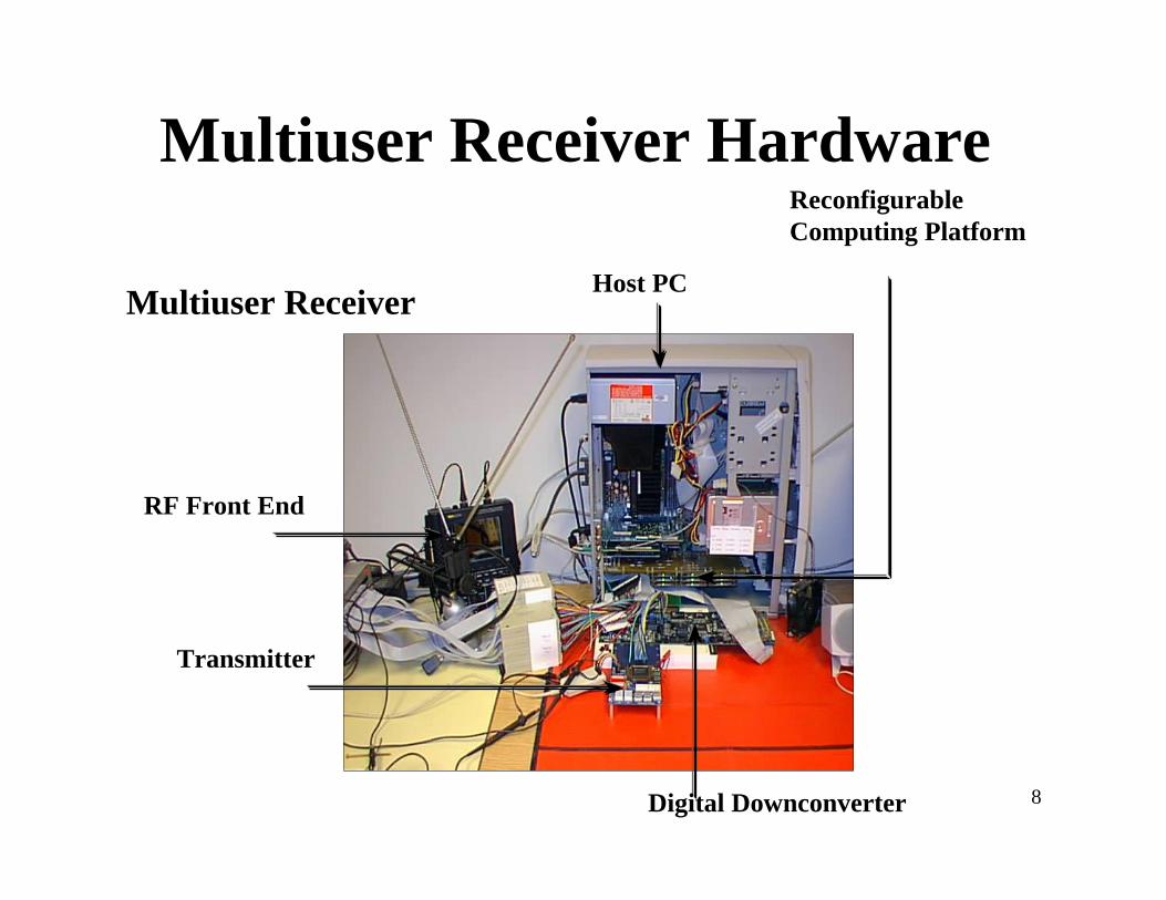
Multiuser Receiver Hardware
Multiuser Receiver
RF Front End
Transmitter
Host PC
ReconfigurableComputing Platform
Digital Downconverter
Page 9
9
Reconfigurable ComputingModules Under Development
• Turbo Coder/Decoder
• Equalizer/ Single User CDMA Receiver
• Symbol/Carrier/Code Synchronizers
• Next Modules→Generic sample rate converter
→Coder/Decoder library
→Demodulator library
Page 10
10
Phase 1 - Proposed Reconfigurable Receiver ArchitecturePhase 1 Implementation of theConfigurable Radio
To Be Determined
Filtering/Adaptive
Equalization
ComplexFIR Filter
Despread
BinaryCorrelator
Sampling
Tracking
Acquisition
NoncoherentDemod
FSKPSK
FEC Decoder
BlockConvolutional
Turbo
De-interleave
AntennaDiversity
Combiner
DigitalDown-
converter
DigitalDown-
converter
RFFront End
RFFront End
ReceiverControl
Host/Network
API
Sigtek ST114
Direction for replacement of DSP µP functionswith reconfigurable computing
Page 11
11
Phase 3 - Proposed Reconfigurable Receiver Architecture (PCI-based)
Graychip
DDC
Graychip
DDC
ANALOG
SUPPLY
PCI-BASEDHOST
INTERFACE
Q FIFO
I FIFO
RF InputCircuitry
Channel 2
CombinerFPGA
RF InputCircuitry
Channel 1
ADC
DSP
ADC
DIGITAL
SUPPLY
SRAM
SRAM
OUTPUTMODULE
FPGA
PROCESSINGMODULE
#1
INPUTMODULE
FPGA
SRAM
SRAM
PROCESSINGMODULE
#2
PROCESSINGMODULE
#4
PROCESSINGMODULE
#3
PROCESSINGMODULE
#6
PROCESSINGMODULE
#5SRAM
SRAM
DP
RAM
I/QMOD
RFOUTPUT
FREQSYNTH
XMITFPGA
CODECANALOG
INPUT
ANALOGSUPPLY
RAM
DAC
DAC
RAM
RAM
SRAM
DPLL
FEC
Phase 3 Final Architecture
Features
● Wider bandwidth front end
● Stallion processor
● Run-time reconfiguration
● Library of communication
functions
Page 12
12
Hardware Based Simulator• Fast simulation engine by taking advantage of
reconfigurable processor
• Supports radio development effort
PC
(Preprocessorfor systemconfigurationand for settingsystemparameters)
reset
mod_sel
θAc
Externalinput
PNsequencegenerator
(Data)
Enable
init_stat
reg length
reset
σ2
seed
Modulator
Receiver
(Demodand datadecisions)
Noisegenerator
2x1MUX
×
×PC
(Post-processorfor datacollectionandanalysis)
I
Q
I
Q
Page 13
13
Adaptive Antenna andDirection Finding Algorithms
and Hardware
Page 14
14
Code Timing
Spatial Filters
Despreaders
ApplicationsDemonstrateinterference
rejection throughspatial filtering
Study algorithmperformance
Perform AoA estimation forposition location applications
Developing spatialchannel models
Third Generation Array
Demodulatorand
BeamformingAlgorithm
Front End for Antenna 1ADC / DDC
(SigTek ST-114)BPF
IFAMP
Local Oscillator
X IF LPF
~f=1982 MHZ
f=2050 MHZ
Front End for Antenna 8ADC / DDC
(SigTek ST-114)BPF IF
AMP
Local Oscillator
X IF LPF
~f=1982 MHZ
f=2050 MHZ
DSPTI C549/C541
Page 15
15
MPRG Vector Measurement SystemMPRG Vector Measurement System● Fully functional 8 elements, 1.25 MHz
Bandwidth, 2.050 GHz centerfrequency
● Flexible for adapting variousantenna/polarization inputs, carrierfrequencies, bandwidths, real-timealgorithms, or data collectionscenarios
● Eight Harris 40214 ProgrammableDirect Digital Downconverters, eightC54x DSPs, one Analog Devices 21010
● New features being added→ CDMA capability→ Improved system executiveprocessing
Page 16
16
Research Issues
• Adaptive array algorithm performancein real situations
• Vector channel measurements
• Practical AOA algorithm andhardware development
• Adaptive array algorithm convergenceissues
Page 17
17
Measurement Result
Channel A signal strength
Channel B signal strength
Signal strength using LSCMA
time
•Indoor environment •2.050 GHz carrier•stationary rx and tx•10 second collect
Page 18
18
Circular Model (Macrocell)*Circular Model (Macrocell)*
• Models macrocell environments• Scatterers are uniformly distributed in a
circular region about the mobile• Approximate radius, 30 m < R < 200 m
CircularScattererRegion
RBase Station
Page 19
19
Joint TOA-AOA (Circular BS View)Joint TOA-AOA (Circular BS View)
f
D c D c c c D
R D c
D cD c
c DR
elseb b
b
m b
b
bm
τ θ τ θτ τ τ θ
π θ ττ θ τ
τ θ, ( , )( )( cos( ))
( cos( ) ):
cos( )
cos( ): .
=− + −
−− +
−≤
2 2 2 2 2 3 2
2 3
2 2 22
4
22
0
3.43.5
3.63.7
3.83.9
4
-5
0
5
-1
-0.5
0
0.5
1
1.5
2
Angle of Arrival (degrees)Time of Arrival (usec)
Prob
abili
ty D
ensi
ty [
log1
0(f)
]
D = 1kmRm= 100m
Page 20
20
Summary of GloMo2Accomplishments
• Over one hundred publications produced
• Three generations of smart antennas built
• Three spread spectrum receivers built
• Vector channel models created
• Fully reconfigurable radio being built