13

We Make Embedded Wireless Easy to Use
AN021: RF MODULES RANGECALCULATIONS AND TEST
Page 1 of 11
APPLICATION NOTE: AN021
2017 Radiocrafts AS Application Note AN021 (rev. 1.0)
RF Modules Range Calculation and Test By T.A.Lunder and P.M.Evjen
Keywords
Definition of Link Budget, Link Margin, Antenna gain, Path loss
Models for indoor and outdoor range
Range calculation
Case studies of range testing
Introduction
Radiocrafts offers a series of RF Modules with integrated wireless communication protocols that are easy to use in a wide range of applications. When selecting the right radio technology, the achievable communication range is an important factor. This document review how to analyse radio range based on parameter provided in the data sheets for the different module families. Some measurement results from practical range testing are also shown.
Link Budget
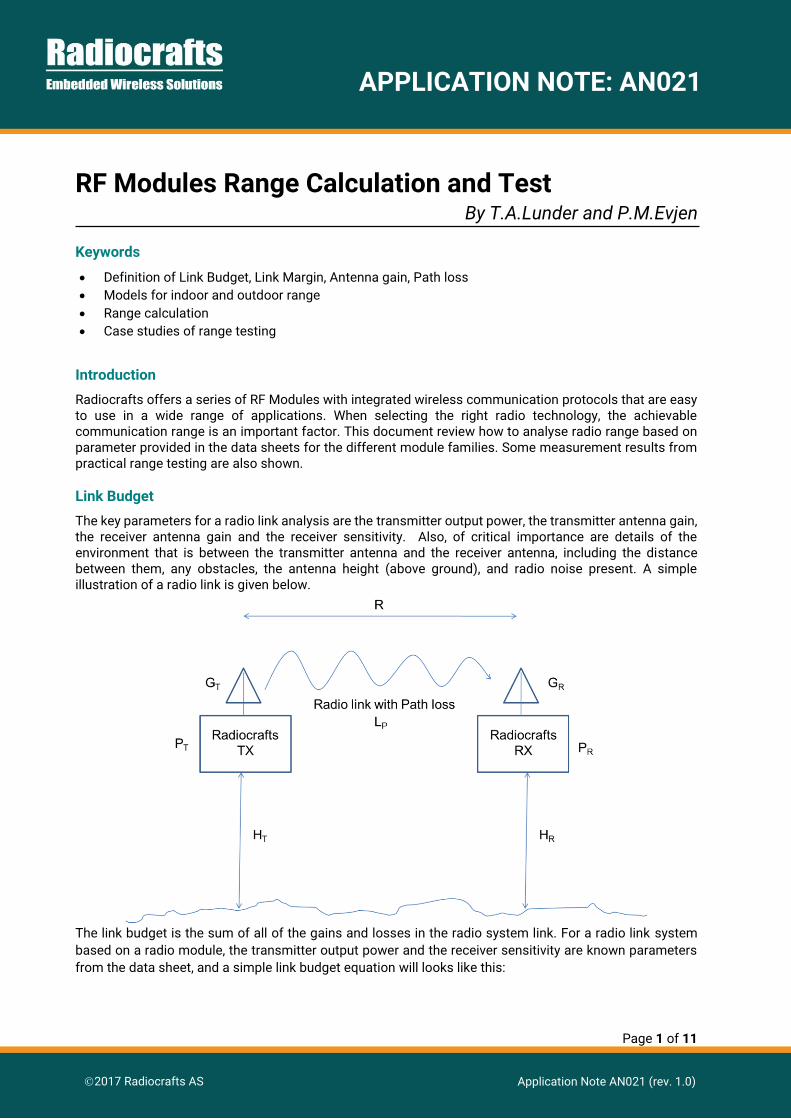
The key parameters for a radio link analysis are the transmitter output power, the transmitter antenna gain, the receiver antenna gain and the receiver sensitivity. Also, of critical importance are details of the environment that is between the transmitter antenna and the receiver antenna, including the distance between them, any obstacles, the antenna height (above ground), and radio noise present. A simple illustration of a radio link is given below.
The link budget is the sum of all of the gains and losses in the radio system link. For a radio link system
based on a radio module, the transmitter output power and the receiver sensitivity are known parameters
from the data sheet, and a simple link budget equation will looks like this:
Page 2 of 11
APPLICATION NOTE: AN021
2017 Radiocrafts AS Application Note AN021 (rev. 1.0)
PR = PT + GT + LP + GR
Where
PR = Received Power (dBm)
PT = Transmitted Power (dBm)
GT = Transmitter antenna Gain (dB)
GR = Receiver antenna Gain (dB)
LP = Path Loss (dB)
Link Margin
The transmitted signal is spread out from the transmitter so that only a fraction of the power reaches to
the receiver. This is represented by the Path Loss (LP) which models the loss of power due to distance and
the antenna area. Because the antenna area (how large area the antenna can catch power from) depends
on the frequency, the path loss is frequency dependent.
A common misunderstanding is that higher frequency signals are attenuated by “space” more than lower
frequencies. This is not the case. The frequency dependency of the Path Loss is just a result of the fact
that the electrical size (and the physical size) of the antenna scales with the wavelength. A low frequency
antenna is larger and therefore has a larger antenna area which can catch more power from the transmitter.
As long as PR is greater than the sensitivity of the RC module, the packet will normally be received correctly.
The link margin, LM, informs about how much margin there is on the communication link before starting to
get packet errors:
LM = PR – SR
LM = PT + GT + LP + GR - SR
Where
PR = Received Power (dBm)
SR = RX Sensitivity (dBm)
LM>0 = Link OK
LM<0 = Link corrupted or errors in packet
Randomly variation of path loss due to fading and environmental RF noise must be taken into account, and
will require you to always have at least few dB Link margin in your deployed destination to ensure reliably
communication over time.
Antenna Gain
An antenna with gain 0dBi is called an isotropic antenna. In a transmitter it spreads power equally in all
directions, and it receives power equally from all directions. An antenna with gain above 0dBi is directional,
and the more the gain the more directional the antenna is. So antenna gain is really a measure of the
antenna's ability to focus the transmitted energy in one direction, or as a receiver, to listen to one direction
and exclude others. A theorem called reciprocity states that it doesn't matter if you use an antenna as a
transmitter or receiver, the gain is always the same. This is an assumption that will be used in the rest of
this document.
Here is a list of the antennas used in the Radiocrafts Development Kit, and their respective gain:
Page 3 of 11
APPLICATION NOTE: AN021
2017 Radiocrafts AS Application Note AN021 (rev. 1.0)
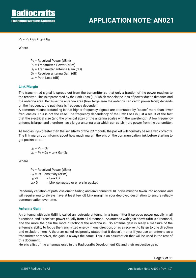
Frequency Band Type Antenna Gain
169 MHz H169-SMA -9 dBi*
433 MHz ANT433QW-SMA 0 dBi
868 / 915 MHz ANT868-915QW-SMA 0 dBi
2.4 GHz ANT433QW-SMA 0 dBi *Low gain due to small ground plane area compare to the wavelength at 169 MHz
A quarter wave antenna on an ideal infinite ground plane, have 5.15 dBi gain. However, on a small ground
plane like the Development Board, the gain will be reduced to approximately 0 dBi.
Path Loss
Path loss (or path attenuation) is the reduction in power density of a radio signal as it propagates through
space. Path loss is a major component in the analysis and design of the link budget of radio systems. The
estimate of the path loss depends on the distance and environment between the transmitter and receiver.
We use propagation models to estimate the path loss LP.
Calculation of the path loss is usually called prediction. Exact prediction is possible only for simpler cases,
such as the above-mentioned free space propagation or the flat-earth model. For practical cases the path
loss is calculated using a variety of approximations. As an overview, three different models (Free space
model, Over-Ground model and Simple indoor model) are presented in the following.
The Free space model assumes that there are no obstructions between the transmitter and receiver, or any
significant reflecting objects (including the ground). The spacing between the transmitter and receiver is R
and the Path Loss is then given by:
LP = P0 – 20*log10 R
Where R is distance in meter between the transmitter and the receiver. P0 is the Path Loss at 1 meter
distance given by:
P0 = 20 * log(300/4*PI*frequency)
P0 for a selection of frequencies are:
P0 @ 169 MHz = -17.0 dB P0 @ 433 MHz = -25.2 dB P0 @ 868 MHz = -31.1 dB P0 @ 915 MHz = -31.6 dB P0 @ 2.4 GHz = -40.4 dB
In the Over-Ground Model, the transmitter is at height HT above flat ground and the receiver is at a height
HR. The distance between the transmitter and the receiver is R. P0 is as defined for the free space model.
The path loss is given by:
LP = P0 – 10*log10 (HT * HR / R*R)
In the Simple Indoor model the type of environment is modelled by an index n. The spacing between the
transmitter and the receiver is R. P0 is as defined for the free space model. The path loss is then given by:

Page 4 of 11
APPLICATION NOTE: AN021
2017 Radiocrafts AS Application Note AN021 (rev. 1.0)
LP = P0 – n*10*log10 R
Some reported values for n are:
n Description
2 Free space
2.2 Retail store
1.8 Grocery store
3 Office, hard partitions
2.6 Office, soft partitions
3.3 Metalworking factory, obstructed line of sight
2.1 – 4.5 General non-LOS in office building
1.2 – 6.5 Different indoor environment over several floors
This Simple Indoor model can also be used when estimating range outdoor in urban environment.
Range Estimate
Absolute maximum range can be calculated by setting the link margin to 0 and first calculate the maximum
path loss the radio link can have before packets are lost. This take place when:
LM = 0
LM = PR – SR = PT + GT + LP + GR - SR = 0
LP = SR – (PT + GT + GG )
The range, R, can now be calculated based on one of the path loss models described above; the Free space
model, Over-Ground model or Simple indoor model.
You will see that you will reach a certain range at a given frequency limited by the link budget. A rule of
thumb for range estimation is that 6 dB increased of margin in the link budget will increase the range by a
factor 2. The link margin is increased by configuring the Radiocrafts module for higher output power or
better sensitivity. Better sensitivity is achieved by using lower data rate or selecting one of the narrowband
modules. Another rule of thumb is that for a given link budget the range will be increased by a factor 2 if
the frequency is reduced by a factor 2.
Case Study 1: 868 MHz Indoor environments
The RC1180-MBUS was tested inside the Radiocrafts headquarter building. The S mode configuration use
the following parameters:
Frequency: 868.3 Mhz
Output power: 9 dBm
Sensitivity: -106 dBm
Antenna gain: 0 dBi
R: 23 meters (6 floors)
N: 5
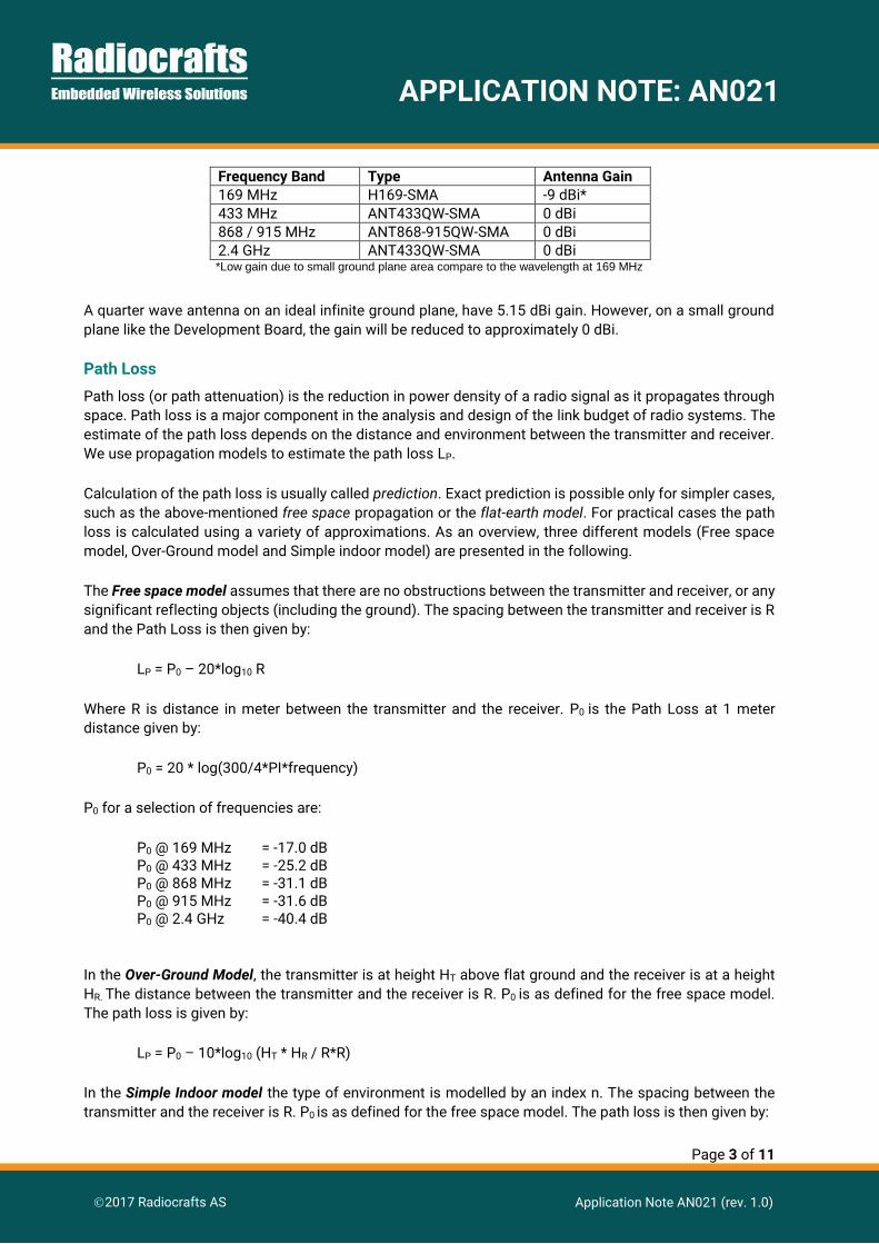
A modelling index of 5 was selected due to link going through several floors and that the transmitter was
located close to an elevator made of steel. The figure illustrates the side view of the Radiocrafts building
and shows the position of the transmitter in 1st floor, and the receiver at the 6th floor.

Page 5 of 11
APPLICATION NOTE: AN021
2017 Radiocrafts AS Application Note AN021 (rev. 1.0)
The simple indoor model gives the following path loss:
PL = P0 – n*10*log10 R
PL = -31.1 dB – 5*10*log10 23 = -31.1 dB – 68.1 dB
PL = - 99.2 dB
The Received power from 1st floor to 6th floor will then be:
PR = PT + GT + LP + GR PR = 9 dBm + 0 dBi -99.2 dB + 0 dBi
PR = - 90.2 dBm
Giving a Link Margin of:
LM = PR – SR
LM = PT + GT + LP + GR – SR
LM = 9 dBm + 0 dBm -99.2 dB + 0 dBm - (-106 dBm)
LM = 15.8 dB
The theoretical value can be verified by a simple range test in the Radiocrafts building. The transmitter
located in the lobby of 1st floor was constantly transmitting packets every 2 seconds. The receiver was
logging all the received packets and recording the RSSI level for each packet. The receiver was carried while
walking from the transmitter at the 1th floor, to the end position at 6th floor, and back again.
Page 6 of 11
APPLICATION NOTE: AN021
2017 Radiocrafts AS Application Note AN021 (rev. 1.0)
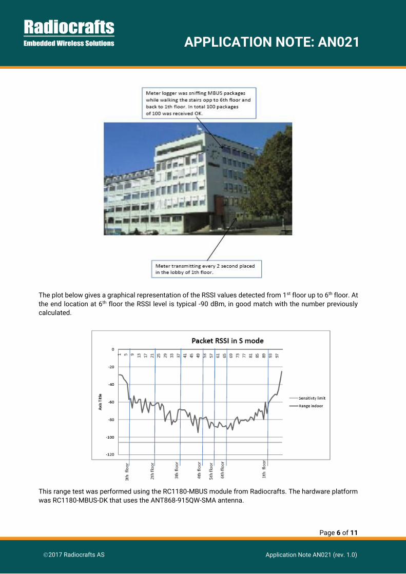
The plot below gives a graphical representation of the RSSI values detected from 1st floor up to 6th floor. At
the end location at 6th floor the RSSI level is typical -90 dBm, in good match with the number previously
calculated.
This range test was performed using the RC1180-MBUS module from Radiocrafts. The hardware platform
was RC1180-MBUS-DK that uses the ANT868-915QW-SMA antenna.

Page 7 of 11
APPLICATION NOTE: AN021
2017 Radiocrafts AS Application Note AN021 (rev. 1.0)
Case study 2: 169 MHz antenna comparison in free line of sight
The RC1700HP-MBUS4 Development Boards including the Kit antenna was used to compare a wide
selection of 169 MHz antennas. This illustrates the antenna Gain differences. A free Line-of-Sight (LoS)
between Holmenkollen and Grefsenkollen in Oslo has a distance of 8.3 km. This line was used as a fixed
location for the antenna comparison test.
The table below summarizes the RSSI level on the receiver for different RX antennas. The TX antenna used
in all tests is antenna A.
The received signal strength (RSSI) differs between the RX antennas, and illustrates the antenna gain
difference compared to antenna A.
The following parameters were used during the test:
RX antenna type
H169-SMA
Vtronix LD20
Vtronix LD74
Vtronix X12B
ANT F02-000
ANT F02-001
Pulse SPWB24150
2JD02 Dipole
Fractus FR01-B3
Antenna ID A B C D E F G H I
RX Polarisation
V V V V V V V V / H V /H
RSSI -88 -81 -75 -88 -84 -88 -90 -83/-92 -93/-96
RSSI noise (no signal)
-114 -102 -101 -114 -101 -114 -100 -99/-104 -126 / -122
Page 8 of 11
APPLICATION NOTE: AN021
2017 Radiocrafts AS Application Note AN021 (rev. 1.0)
Frequency: 169 Mhz
Output power: +27 dBm
Data rate: 2.4 kbps
Sensitivity: -119 dBm
Antenna gain TX: -9 dBi
The free space model gives a path loss of:
LP = P0 – 20*log10 R
LP = -17 dBm – 20*log10 (8300)
LP = -95.4 dB
When using the antenna A also at the receiver side, the Link margin is:
LM = PR – SR
LM = PT + GT + LP + GR – SR
LM = +27 dBm -9 dBm -95.4 dB - 9 dBm - (-119 dBm)
LM = 32.6 dB
This margin shows that RC1700HP will reach much longer than 8 km in free line of sight range since. In
theory, 6 dB margin gives twice the range. With more than 30 dB margin, we would reach 32 times longer.
Page 9 of 11
APPLICATION NOTE: AN021
2017 Radiocrafts AS Application Note AN021 (rev. 1.0)
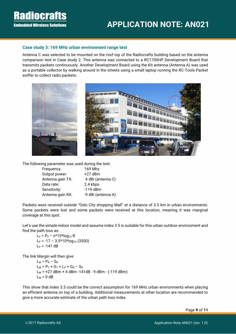
Case study 3: 169 MHz urban environment range test
Antenna C was selected to be mounted on the roof top of the Radiocrafts building based on the antenna
comparison test in Case study 2. This antenna was connected to a RC1700HP Development Board that
transmits packets continuously. Another Development Board using the Kit antenna (Antenna A) was used
as a portable collector by walking around in the streets using a small laptop running the RC-Tools Packet
sniffer to collect radio packets.
The following parameter was used during the test:
Frequency: 169 Mhz
Output power: +27 dBm
Antenna gain TX: 4 dBi (antenna C)
Data rate: 2.4 kbps
Sensitivity: -119 dBm
Antenna gain RX: -9 dBi (antenna A)
Packets were received outside “Oslo City shopping Mall” at a distance of 3.5 km in urban environments.
Some packets were lost and some packets were received at this location, meaning it was marginal
coverage at this spot.
Let’s use the simple indoor model and assume index 3.5 is suitable for this urban outdoor environment and
find the path loss as:
LP = P0 – n*10*log10 R
LP = -17 – 3.5*10*log10 (3500)
LP = -141 dB
The link Margin will then give:
LM = PR – SR
LM = PT + GT + LP + GR – SR
LM = +27 dBm + 4 dBm -141dB - 9 dBm - (-119 dBm)
LM = 0 dB
This show that index 3.5 could be the correct assumption for 169 MHz urban environments when placing
an efficient antenna on top of a building. Additional measurements at other location are recommended to
give a more accurate estimate of the urban path loss index.
Page 10 of 11
APPLICATION NOTE: AN021
2017 Radiocrafts AS Application Note AN021 (rev. 1.0)
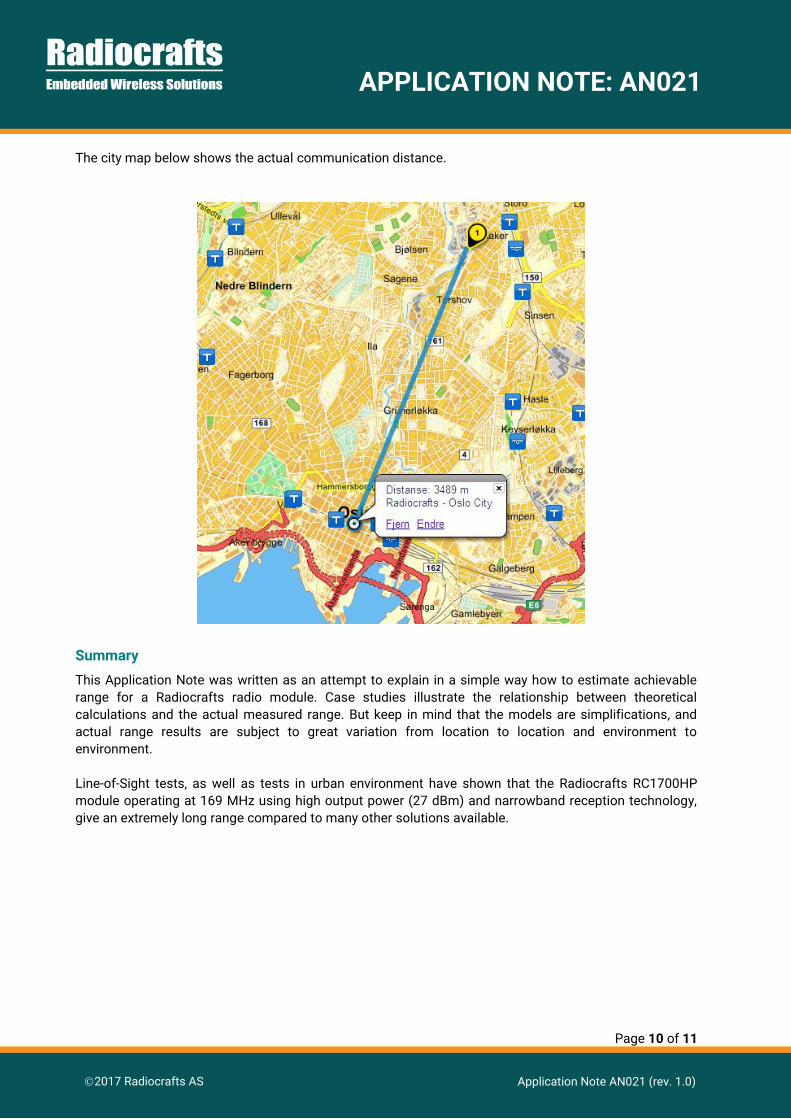
The city map below shows the actual communication distance.
Summary
This Application Note was written as an attempt to explain in a simple way how to estimate achievable
range for a Radiocrafts radio module. Case studies illustrate the relationship between theoretical
calculations and the actual measured range. But keep in mind that the models are simplifications, and
actual range results are subject to great variation from location to location and environment to
environment.
Line-of-Sight tests, as well as tests in urban environment have shown that the Radiocrafts RC1700HP
module operating at 169 MHz using high output power (27 dBm) and narrowband reception technology,
give an extremely long range compared to many other solutions available.
Page 11 of 11
APPLICATION NOTE: AN021
2017 Radiocrafts AS Application Note AN021 (rev. 1.0)
Document Revision History
Document Revision Changes 1.0 First release
Disclaimer
Radiocrafts AS believes the information contained herein is correct and accurate at the time of this printing. However, Radiocrafts AS
reserves the right to make changes to this product without notice. Radiocrafts AS does not assume any responsibility for the use of
the described product; neither does it convey any license under its patent rights, or the rights of others. The latest updates are available
at the Radiocrafts website or by contacting Radiocrafts directly.
As far as possible, major changes of product specifications and functionality, will be stated in product specific Errata Notes published
at the Radiocrafts website. Customers are encouraged to check regularly for the most recent updates on products and support tools.
Trademarks
RC232™ is a trademark of Radiocrafts AS. The RC232™ Embedded RF Protocol is used in a range of products from Radiocrafts. The
protocol handles host communication, data buffering, error check, addressing and broadcasting. It supports point-to-point, point-to-
multipoint and peer-to-peer network topologies.
All other trademarks, registered trademarks and product names are the sole property of their respective owners.
Life Support Policy
This Radiocrafts product is not designed for use in life support appliances, devices, or other systems where malfunction can
reasonably be expected to result in significant personal injury to the user, or as a critical component in any life support device or
system whose failure to perform can be reasonably expected to cause the failure of the life support device or system, or to affect its
safety or effectiveness. Radiocrafts AS customers using or selling these products for use in such applications do so at their own risk
and agree to fully indemnify Radiocrafts AS for any damages resulting from any improper use or sale.
© 2017, Radiocrafts AS. All rights reserved.

www.radiocrafts.com
Email: [email protected]
Tel: +47 4000 5195
For More Information,Please Visit Our Website!
VISIT NOW


