ISL29125EVAL1ZEvaluation Hardware/Software User Manual for RGB Sensor
Introduction The RGB Evaluation Kit is designed to evaluate the performance of the RGB sensor. The kit is accompanied by a Graphical User Interface (GUI) that contains the CIE 1931 Chromaticity diagram with Planckian locus in an x, y- coordinate system, with cross marks to point out where the RGB sensor position is on the graph. The GUI facilitates evaluation of parameters such as raw data of Red, Green and Blue as well as X, Y and Z corrected lux measurements and also performs interrupt functions. Data can be viewed on the GUI and/or saved to a text file for future analysis. The GUI software is compatible with Windows XP®, Windows Vista®, Windows® 7 and Windows® 8. This provides a simple user interface for exercising the device features.
The system (MCU, DUT) is powered directly from the universal serial bus (USB) or from a single-supply voltage of 2.25V to 3.6V. The evaluation board must be connected to a computer through the mini USB port for the system to function. The system uses a USB MCU to communicate to the DUT via I2C/SMBus interface.
Reference DocumentsRGB Chroma Meter Setup
Standard Illuminants
Chromaticity
Color temperature
Planckian locus
Colour & Vision Research laboratory
Mired
CIELUV
Least Squares
Linear Regression
CIE 1960 Color Space (MacAdam - uv)
Wratten Number
Evaluation Package (Online Order)The package consists of the hardware, software and documentation listed in the following:
• User Guide (Online)
• ISL29125 Datasheet (Online)
• Presentation (Installer File)
• uv-xy table (Installer File)
• CCM Calibration Worksheet (Installer File)
• User Guide (Installer File)
Hardware Requirements• Mini USB cable
• Evaluation board
Installation of the Graphical User Interface (GUI) Software and USB DriverDownload the software from the ISL29125EVAL1Z page.
Once the application is downloaded from the website, double-click the file to start installing the GUI. The user will be greeted by the screen shown in Figure 2. Continue through the installer and read the instructions. Figures 2 through 6 show the complete installation process.
The USB evaluation board should always be connected via the USB until the installation has been satisfactorily completed.
Running Program for the RGB GUIA) USB Communication (Hardware) - Gather the required
materials and connect the PC to the ISL29125 by mini USB cable as shown in Figure 7.
Once the evaluation board is connected to the PC, D6, which is next to mini USB socket at the bottom of evaluation board, should light up. If the LED is not ON, please check your connection.
B) Launching the RGB GUI - Once the installation is complete, click “Finish” to launch the RGB GUI. If you wish to launch from your PC desktop, us the path shown in Figure 8. (Start Program Intersil RGB Chroma Meter Chroma Meter.
C) Once “ChromaMeter” is clicked, the window displayed in Figure 9 should open. If it does not display cross-points in the Chromaticity diagram on the right and numbers on the left panel of GUI, then check your connections. If the problem still persists, then you may want to restart the software. Figure 12 shows the error message that displays if the evaluation board is improperly attached.
D) Figure 9 shows an example using the ISL29125. Please note that all demonstrations within this document use the ISL29125.
A detailed explanation of the operating modes can be found in the datasheet of the individual devices and Figure 10 details the GUI display.
FIGURE 7. ISL29125 EVALUATION BOARD CONNECTED TO PC BY MINI USB
FIGURE 8. INSTALLATION READY TO INSTALL SCREEN
FIGURE 9. CHROMA TEST GUI
AN1914 Rev 4.0 Page 3 of 8May 12, 2021
ISL29125EVAL1Z
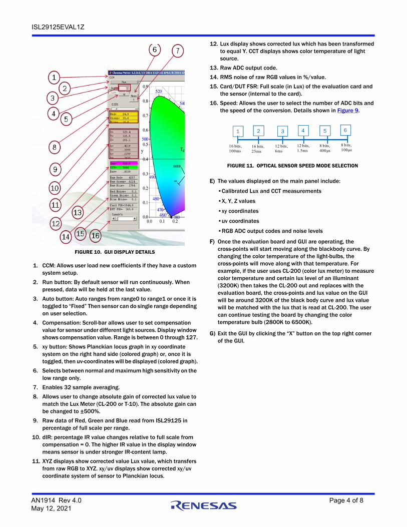
1. CCM: Allows user load new coefficients if they have a custom system setup.
2. Run button: By default sensor will run continuously. When pressed, data will be held at the last value.
3. Auto button: Auto ranges from range0 to range1 or once it is toggled to “Fixed” Then sensor can do single range depending on user selection.
4. Compensation: Scroll-bar allows user to set compensation value for sensor under different light sources. Display window shows compensation value. Range is between 0 through 127.
5. xy button: Shows Planckian locus graph in xy coordinate system on the right hand side (colored graph) or, once it is toggled, then uv-coordinates will be displayed (colored graph).
6. Selects between normal and maximum high sensitivity on the low range only.
7. Enables 32 sample averaging.
8. Allows user to change absolute gain of corrected lux value to match the Lux Meter (CL-200 or T-10). The absolute gain can be changed to ±500%.
9. Raw data of Red, Green and Blue read from ISL29125 in percentage of full scale per range.
10. dIR: percentage IR value changes relative to full scale from compensation = 0. The higher IR value in the display window means sensor is under stronger IR-content lamp.
11. XYZ displays show corrected value Lux value, which transfers from raw RGB to XYZ. xy/uv displays show corrected xy/uv coordinate system of sensor to Planckian locus.
12. Lux display shows corrected lux which has been transformed to equal Y. CCT displays shows color temperature of light source.
13. Raw ADC output code.
14. RMS noise of raw RGB values in %/value.
15. Card/DUT FSR: Full scale (in Lux) of the evaluation card and the sensor (internal to the card).
16. Speed: Allows the user to select the number of ADC bits and the speed of the conversion. Details shown in Figure 9.
E) The values displayed on the main panel include:
•Calibrated Lux and CCT measurements
•X, Y, Z values
•xy coordinates
•uv coordinates
•RGB ADC output codes and noise levels
F) Once the evaluation board and GUI are operating, the cross-points will start moving along the blackbody curve. By changing the color temperature of the light-bulbs, the cross-points will move along with that temperature. For example, if the user uses CL-200 (color lux meter) to measure color temperature and certain lux level of an illuminant (3200K) then takes the CL-200 out and replaces with the evaluation board, the cross-points and lux value on the GUI will be around 3200K of the black body curve and lux value will be matched with the lux that is read at CL-200. The user can continue testing the board by changing the color temperature bulb (2800K to 6500K).
G) Exit the GUI by clicking the “X” button on the top right corner of the GUI.
FIGURE 10. GUI DISPLAY DETAILS
1 2 3 4 5 6
16 bits,100ms
16 bits,25ms
12 bits,6ms
12 bits,1.5ms
8 bits,400µs
8 bits,100µs
FIGURE 11. OPTICAL SENSOR SPEED MODE SELECTION
AN1914 Rev 4.0 Page 4 of 8May 12, 2021
ISL29125EVAL1Z
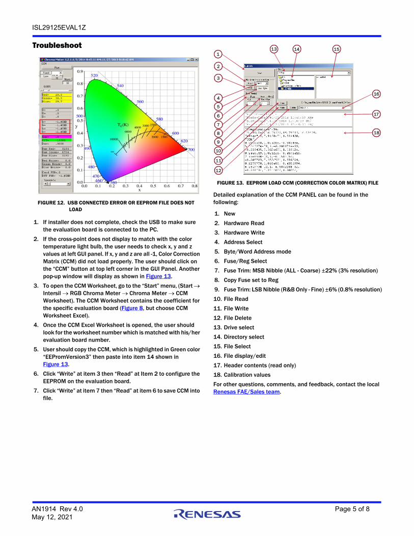
Troubleshoot
1. If installer does not complete, check the USB to make sure the evaluation board is connected to the PC.
2. If the cross-point does not display to match with the color temperature light bulb, the user needs to check x, y and z values at left GUI panel. If x, y and z are all -1, Color Correction Matrix (CCM) did not load properly. The user should click on the “CCM” button at top left corner in the GUI Panel. Another pop-up window will display as shown in Figure 13.
3. To open the CCM Worksheet, go to the “Start” menu, (Start Intersil RGB Chroma Meter Chroma Meter CCM Worksheet). The CCM Worksheet contains the coefficient for the specific evaluation board (Figure 8, but choose CCM Worksheet Excel).
4. Once the CCM Excel Worksheet is opened, the user should look for the worksheet number which is matched with his/her evaluation board number.
5. User should copy the CCM, which is highlighted in Green color “EEPromVersion3” then paste into item 14 shown in Figure 13.
6. Click “Write” at item 3 then “Read” at Item 2 to configure the EEPROM on the evaluation board.
7. Click “Write” at item 7 then “Read” at item 6 to save CCM into file.
Detailed explanation of the CCM PANEL can be found in the following:
4.0 May 12, 2021 Updated links throughout.Added Revision History section.
AN1914 Rev 4.0 Page 8 of 8May 12, 2021
Corporate HeadquartersTOYOSU FORESIA, 3-2-24 Toyosu,Koto-ku, Tokyo 135-0061, Japanwww.renesas.com
Contact InformationFor further information on a product, technology, the most up-to-date version of a document, or your nearest sales office, please visit:www.renesas.com/contact/
TrademarksRenesas and the Renesas logo are trademarks of Renesas Electronics Corporation. All trademarks and registered trademarks are the property of their respective owners.
IMPORTANT NOTICE AND DISCLAIMER
RENESAS ELECTRONICS CORPORATION AND ITS SUBSIDIARIES (“RENESAS”) PROVIDES TECHNICAL SPECIFICATIONS AND RELIABILITY DATA (INCLUDING DATASHEETS), DESIGN RESOURCES (INCLUDING REFERENCE DESIGNS), APPLICATION OR OTHER DESIGN ADVICE, WEB TOOLS, SAFETY INFORMATION, AND OTHER RESOURCES “AS IS” AND WITH ALL FAULTS, AND DISCLAIMS ALL WARRANTIES, EXPRESS OR IMPLIED, INCLUDING, WITHOUT LIMITATION, ANY IMPLIED WARRANTIES OF MERCHANTABILITY, FITNESS FOR A PARTICULAR PURPOSE, OR NON-INFRINGEMENT OF THIRD PARTY INTELLECTUAL PROPERTY RIGHTS.
These resources are intended for developers skilled in the art designing with Renesas products. You are solely responsible for (1) selecting the appropriate products for your application, (2) designing, validating, and testing your application, and (3) ensuring your application meets applicable standards, and any other safety, security, or other requirements. These resources are subject to change without notice. Renesas grants you permission to use these resources only for development of an application that uses Renesas products. Other reproduction or use of these resources is strictly prohibited. No license is granted to any other Renesas intellectual property or to any third party intellectual property. Renesas disclaims responsibility for, and you will fully indemnify Renesas and its representatives against, any claims, damages, costs, losses, or liabilities arising out of your use of these resources. Renesas' products are provided only subject to Renesas' Terms and Conditions of Sale or other applicable terms agreed to in writing. No use of any Renesas resources expands or otherwise alters any applicable warranties or warranty disclaimers for these products.