2018 Microchip Technology Inc. DS00002686A-page 1 INTRODUCTION The IEEE 802.3 Ethernet Compliance testing encompasses a wide range of tests that utilize different waveforms for the various device speeds: • 10BASE-T: Four waveforms (link pulse/idle, pseudo-random, all ones, and arbitrary waveform signal) • 100BASE-TX: Two waveforms (transmit scrambled idle and arbitrary waveform signal) • 1000BASE-T: Five waveforms (four test mode 1-4 waveforms and arbitrary waveform signal) The register settings apply to the PHY registers for most of Microchip’s Ethernet products. Note: The test setup and figures are with a Tektronix scope, TDSET3 Ethernet Compliance Software, and TF-GBE test fixture board. The Twisted Pair Model (TPM) is on the test fixture board. 10BASE-T COMPLIANCE TESTING The 10BASE-T compliance tests are: • Link Pulse Testing • Medium Attachment Unit (MAU) • TP_IDL • Jitter • Differential Voltage • Harmonics • Transmitter Return Loss • Receiver Return Loss • Common-Mode Voltage Link Pulse Testing and TP_IDL are tested with and without the Twisted Pair Model. Each test section below provides the test description, test setup details, and pass criteria. For 10BASE-T test data transmission (pseudo-random and all ones patterns) on KSZ switches, KSZ Gigabit PHYs and LAN PHYs (other than LAN78xx which can generate test patterns itself), use the link partner (set to forced 10BASE-T) to transmit the signal to the device under test (DUT) and enable remote loopback on the DUT. For 10BASE-T test data transmission (pseudo-random and all ones patterns) on KSZ80xx PHYs, the PHY is connected to the MAC of a switch via MII/RMII connection. The link partner transmits the test signal to the switch’s PHY port and through the MII/RMII to the DUT’s PHY port. Link Pulse Testing This is a test of the 10BASE-T Link Pulse signal integrity. For link pulse testing without Twisted Pair Model, the DUT is connected to the DUT port for the 10BASE-T Parametric/ Template Test (some boards may add ‘without Twisted Pair Model’), and the oscilloscope probe is attached to the test jumper. For link pulse testing with Twisted Pair Model, the DUT is connected to the DUT port for the 10BASE-T Parametric/Tem- plate Test with Twisted Pair Model, and the oscilloscope probe is attached to the test jumper after load selection. To configure the DUT for link pulse testing, refer to 10BASE-T Link Pulse Setting on any part for register settings. Pass specification is based on the Link Pulse remaining inside the mask for both the head and the tail. AN2686 Ethernet Compliance Testing for 10BASE-T, 100BASE-TX, and 1000BASE-T Author: John MacKay Microchip Technology Inc.
Transcript
AN2686Ethernet Compliance Testing for 10BASE-T,
100BASE-TX, and 1000BASE-T
INTRODUCTION
The IEEE 802.3 Ethernet Compliance testing encompasses a wide range of tests that utilize different waveforms for thevarious device speeds:
• 10BASE-T: Four waveforms (link pulse/idle, pseudo-random, all ones, and arbitrary waveform signal)
• 100BASE-TX: Two waveforms (transmit scrambled idle and arbitrary waveform signal)
• 1000BASE-T: Five waveforms (four test mode 1-4 waveforms and arbitrary waveform signal)
The register settings apply to the PHY registers for most of Microchip’s Ethernet products.
Note: The test setup and figures are with a Tektronix scope, TDSET3 Ethernet Compliance Software, and TF-GBEtest fixture board. The Twisted Pair Model (TPM) is on the test fixture board.
10BASE-T COMPLIANCE TESTING
The 10BASE-T compliance tests are:
• Link Pulse Testing
• Medium Attachment Unit (MAU)
• TP_IDL
• Jitter
• Differential Voltage
• Harmonics
• Transmitter Return Loss
• Receiver Return Loss
• Common-Mode Voltage
Link Pulse Testing and TP_IDL are tested with and without the Twisted Pair Model. Each test section below providesthe test description, test setup details, and pass criteria.
For 10BASE-T test data transmission (pseudo-random and all ones patterns) on KSZ switches, KSZ Gigabit PHYs andLAN PHYs (other than LAN78xx which can generate test patterns itself), use the link partner (set to forced 10BASE-T)to transmit the signal to the device under test (DUT) and enable remote loopback on the DUT.
For 10BASE-T test data transmission (pseudo-random and all ones patterns) on KSZ80xx PHYs, the PHY is connectedto the MAC of a switch via MII/RMII connection. The link partner transmits the test signal to the switch’s PHY port andthrough the MII/RMII to the DUT’s PHY port.
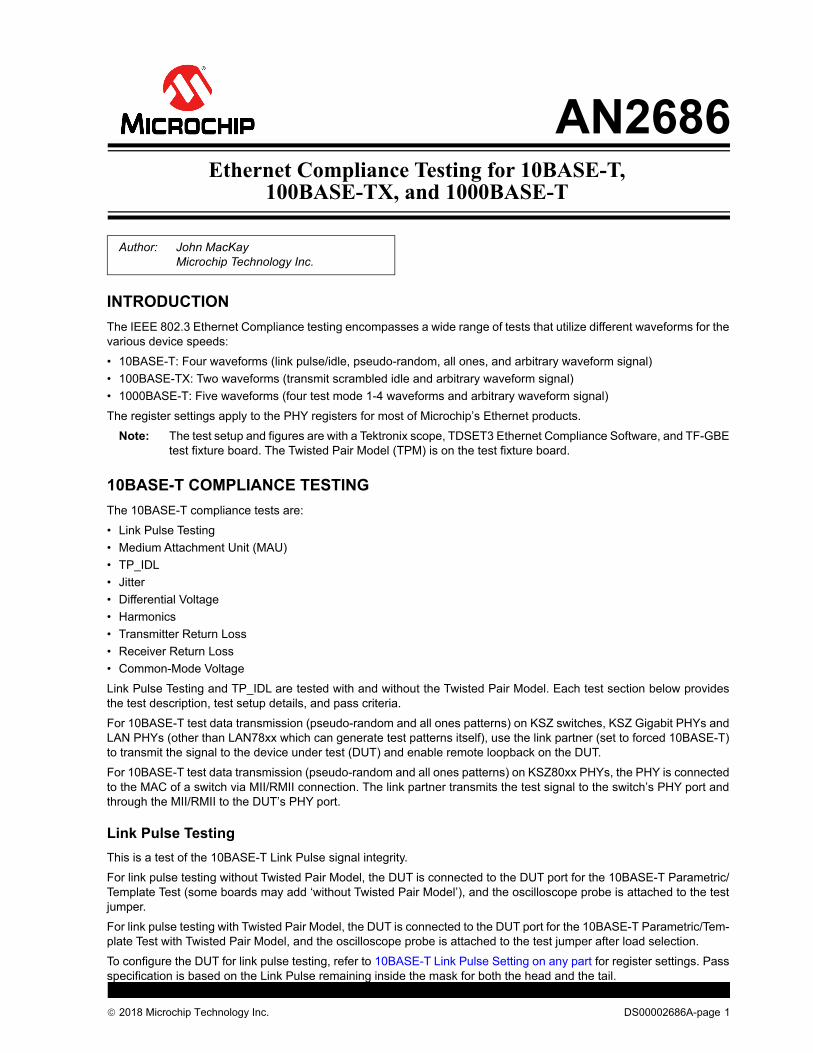
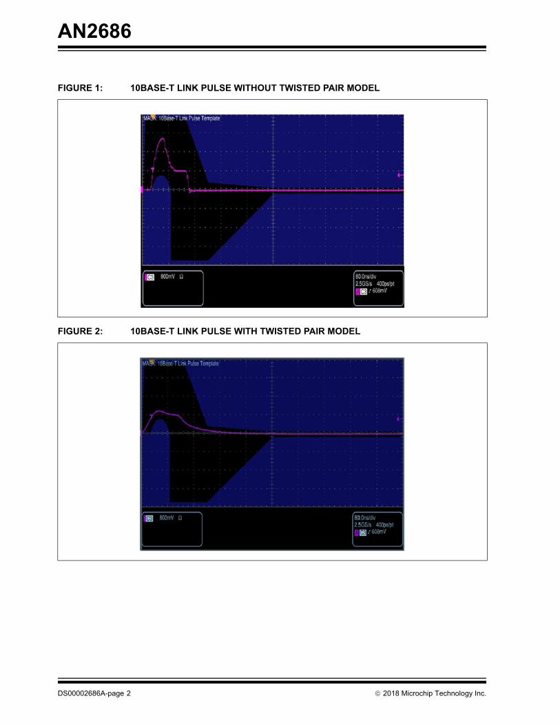
Link Pulse Testing
This is a test of the 10BASE-T Link Pulse signal integrity.
For link pulse testing without Twisted Pair Model, the DUT is connected to the DUT port for the 10BASE-T Parametric/Template Test (some boards may add ‘without Twisted Pair Model’), and the oscilloscope probe is attached to the testjumper.
For link pulse testing with Twisted Pair Model, the DUT is connected to the DUT port for the 10BASE-T Parametric/Tem-plate Test with Twisted Pair Model, and the oscilloscope probe is attached to the test jumper after load selection.
To configure the DUT for link pulse testing, refer to 10BASE-T Link Pulse Setting on any part for register settings. Passspecification is based on the Link Pulse remaining inside the mask for both the head and the tail.
Author: John MacKayMicrochip Technology Inc.
2018 Microchip Technology Inc. DS00002686A-page 1
AN2686
FIGURE 1: 10BASE-T LINK PULSE WITHOUT TWISTED PAIR MODEL
FIGURE 2: 10BASE-T LINK PULSE WITH TWISTED PAIR MODEL
DS00002686A-page 2 2018 Microchip Technology Inc.
AN2686
Medium Attachment Unit (MAU)
This is a test of the MAU of the PHY. The DUT is connected to the DUT port for the 10BASE-T Parametric/TemplateTest with Twisted Pair Model, and the oscilloscope probe is attached to the test jumper. To configure the DUT for MAUtesting, refer to the 10BASE-T Loopback Mode on KSZ parts register settings. For LAN78xx, refer to 10BASE-TPseudo-Random Signal Setting – LAN78xx for register settings. On the oscilloscope, set for internal or external. Shortthe 100-ohm jumper on the test board. Pass specification is based on the signal remaining inside the mask.
FIGURE 3: 10BASE-T MAU - EXTERNAL
FIGURE 4: 10BASE-T MAU - INTERNAL
2018 Microchip Technology Inc. DS00002686A-page 3
AN2686
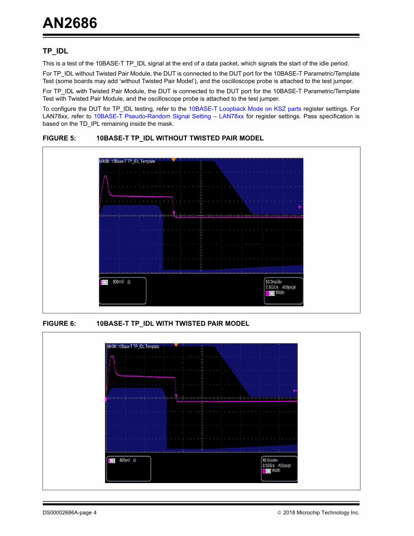
TP_IDL
This is a test of the 10BASE-T TP_IDL signal at the end of a data packet, which signals the start of the idle period.
For TP_IDL without Twisted Pair Module, the DUT is connected to the DUT port for the 10BASE-T Parametric/TemplateTest (some boards may add ‘without Twisted Pair Model’), and the oscilloscope probe is attached to the test jumper.
For TP_IDL with Twisted Pair Module, the DUT is connected to the DUT port for the 10BASE-T Parametric/TemplateTest with Twisted Pair Module, and the oscilloscope probe is attached to the test jumper.
To configure the DUT for TP_IDL testing, refer to the 10BASE-T Loopback Mode on KSZ parts register settings. ForLAN78xx, refer to 10BASE-T Pseudo-Random Signal Setting – LAN78xx for register settings. Pass specification isbased on the TD_IPL remaining inside the mask.
FIGURE 5: 10BASE-T TP_IDL WITHOUT TWISTED PAIR MODEL
FIGURE 6: 10BASE-T TP_IDL WITH TWISTED PAIR MODEL
DS00002686A-page 4 2018 Microchip Technology Inc.
AN2686
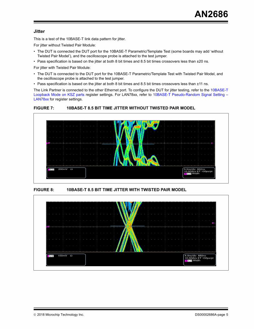
Jitter
This is a test of the 10BASE-T link data pattern for jitter.
For jitter without Twisted Pair Module:
• The DUT is connected the DUT port for the 10BASE-T Parametric/Template Test (some boards may add ‘without Twisted Pair Model’), and the oscilloscope probe is attached to the test jumper.
• Pass specification is based on the jitter at both 8 bit times and 8.5 bit times crossovers less than ±20 ns.
For jitter with Twisted Pair Module:
• The DUT is connected to the DUT port for the 10BASE-T Parametric/Template Test with Twisted Pair Model, and the oscilloscope probe is attached to the test jumper.
• Pass specification is based on the jitter at both 8 bit times and 8.5 bit times crossovers less than ±11 ns.
The Link Partner is connected to the other Ethernet port. To configure the DUT for jitter testing, refer to the 10BASE-TLoopback Mode on KSZ parts register settings. For LAN78xx, refer to 10BASE-T Pseudo-Random Signal Setting –LAN78xx for register settings.
FIGURE 7: 10BASE-T 8.5 BIT TIME JITTER WITHOUT TWISTED PAIR MODEL
FIGURE 8: 10BASE-T 8.5 BIT TIME JITTER WITH TWISTED PAIR MODEL
2018 Microchip Technology Inc. DS00002686A-page 5
AN2686
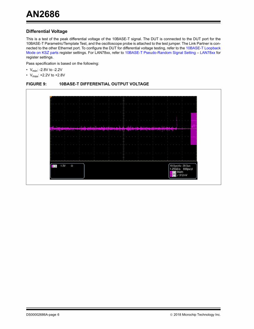
Differential Voltage
This is a test of the peak differential voltage of the 10BASE-T signal. The DUT is connected to the DUT port for the10BASE-T Parametric/Template Test, and the oscilloscope probe is attached to the test jumper. The Link Partner is con-nected to the other Ethernet port. To configure the DUT for differential voltage testing, refer to the 10BASE-T LoopbackMode on KSZ parts register settings. For LAN78xx, refer to 10BASE-T Pseudo-Random Signal Setting – LAN78xx forregister settings.
Pass specification is based on the following:
• Vmin: -2.8V to -2.2V
• Vmax: +2.2V to +2.8V
FIGURE 9: 10BASE-T DIFFERENTIAL OUTPUT VOLTAGE
DS00002686A-page 6 2018 Microchip Technology Inc.
AN2686
Harmonic Distortion
This is a test of the harmonic distortion of the 10BASE-T signal. The DUT is connected to the DUT port for the 10BASE-T Parametric/Template Test, and the oscilloscope probe is attached to the test jumper. The Link Partner is connected tothe other Ethernet port. To configure the DUT for harmonic distortion testing, refer to the 10BASE-T Loopback Mode onKSZ parts register settings. For LAN78xx, refer to the10BASE-T All Ones Signal for Harmonic Distortion – LAN78xx forregister settings. Pass specification is based on all harmonics being more than 27 dB less than the fundamental signal.
Transmitter Return Loss
This is a test of the transmitter return loss. A differential signal (positive and negative) must be provided externally froma waveform generator to the test board. The differential signal is fed back to the oscilloscope running the return lossmeasurements. Two oscilloscope channel probes are attached to the pair A jumpers for return loss measurement.
For the calibrations for short, open, and load, use the same type of Ethernet cable (straight or crossover) for measure-ment of the DUT transmitter return loss. For each calibration, connect the Ethernet port on the Differential Return Lossportion to the corresponding Ethernet port on the calibration board attachment for the compliance test board. Once thecalibrations are applied, run the test with the DUT. Pass specification is based on the return loss remaining under themask.
FIGURE 10: 10BASE-T HARMONIC DISTORTION
FIGURE 11: 10BASE-T TRANSMITTER RETURN LOSS
2018 Microchip Technology Inc. DS00002686A-page 7
AN2686
Receiver Return Loss
This is a test of the receiver return loss. A differential signal (positive and negative) must be provided externally from awaveform generator to the test board. The differential signal is fed back to the oscilloscope running the return loss mea-surements. Two oscilloscope channel probes are attached to the pair B jumpers for return loss measurement.
For the calibrations for short, open, and load, use the same type of Ethernet cable (straight or crossover) for measure-ment of the DUT receiver return loss. For each calibration, connect the Ethernet port on the Differential Return Lossportion to the corresponding Ethernet port on the calibration board attachment for the compliance test board. Once thecalibrations are applied, run the test with the DUT. Pass specification is based on the return loss remaining under themask.
Common-Mode Voltage
This is a test of the common-mode voltage of the 10BASE-T signal. The DUT is connected to the DUT port for the Com-mon-Mode Output Voltage Test, and the oscilloscope cable is connected to the test cable port. Use a jumper to shortthe differential pair A. To configure the DUT for common-mode voltage testing, refer to 10BASE-T Loopback Mode onKSZ parts register settings. For LAN78xx, refer to the 10BASE-T Pseudo-Random Signal Setting – LAN78xx for registersettings. Pass specification is based on common-mode voltage less than 50 mV.
FIGURE 12: 10BASE-T RECEIVER RETURN LOSS
FIGURE 13: 10BASE-T COMMON-MODE VOLTAGE
DS00002686A-page 8 2018 Microchip Technology Inc.
AN2686
10BASE-T Compliance Test Signal Generation
Note: W 00 0100h is a write to PHY register 00 of value 0100 in hexadecimal.
For 10BASE-T compliance test on any part, the link pulse and auto-MDIX can be set with the following:
For KSZxxxx parts, the rest of the testing is done by enabling the remote loopback, forcing MDI mode, and disablingAuto-MDIX.
For LANxxxx parts other than LAN78xx, the rest of the testing is done by enabling loopback mode, forcing MDI mode,and disabling Auto-MDIX. The following enables loopback:
For LAN78xx, a packet generator is available to generate the pseudo-random and all ones signals for the remainder ofthe 10BASE-T compliance testing. The following enables these modes:
10BASE-T Link Pulse Setting on any part
W 00 0100h // Sets link to 10 Mbps without auto-negotiation
10BASE-T Loopback Mode on KSZ parts
For KSZ9xxx PHYs and KSZ Switches:
W 00 0100h // Sets link to 10 Mbps - Full Duplex, Disables Auto-Negotiation
W 11 bit[8] = 1 // Enables remote loopback
W 1C 00C0 // Forces MDI mode and disables Auto-MDIX
For KSZ8xxx PHYs:
W 00 0100h // Sets link to 10 Mbps - Full Duplex, Disables Auto-Negotiation
W 1F A000 // Forces MDI mode and disables Auto-MDIX
10BASE-T Loopback Mode on LAN parts (except LAN78xx)
W 00 4100h // Enables Loopback, Sets link to 10 Mbps - Full Duplex, Disables Auto-Negotiation
W 11 A000h // Forces MDI mode and disables Auto-MDIX (Note: Write 0020h for LAN7500)
10BASE-T Pseudo-Random Signal Setting – LAN78xx
W 12 0020h // Disables Auto-MDIX
W 00 0100h // Sets link to 10 Mbps without auto-negotiation
W 1f 0001h // Sets to Ethernet Page 1 Access
W 13 0008h // Force MDI mode
W 1d 33FEh // Resets the packet generation
W 1d F3FEh // Sets link to send packets continuously, the destination MAC and source MAC to set to FF:FF:FF:FF:FF:FF (broadcast), random pay-load data with good CRCs
10BASE-T All Ones Signal for Harmonic Distortion – LAN78xx
W 12 0020h // Disables Auto-MDIX
W 00 0100h // Sets link to 10 Mbps without auto-negotiation
W 1f 0001h // Sets to Ethernet Page 1 Access
W 13 0008h // Force MDI mode
W 1e FFFFh // Sets packet generator to send FFFF each 16 bits of payload data, which is all ones
W 1d 33FCh // Resets the packet generation payload to the new payload pattern written to the ECG register in the previous step
W 1d F3FCh // Sets link to send packets continuously, the destination MAC and source MAC to set to FF:FF:FF:FF:FF:FF (broadcast), fixed payload data with good CRCs
2018 Microchip Technology Inc. DS00002686A-page 9
AN2686
100BASE-TX COMPLIANCE TESTING
The 100BASE-TX compliance tests are:
• Template
• Differential Output Voltage
• Signal Amplitude Symmetry
• Rise Time
• Fall Time
• Rise Time/Fall Time Symmetry
• Waveform Overshoot
• Transmit Jitter
• Distortion Based on Duty Cycle
• Transmitter Return Loss
• Receiver Return Loss
All tests use transmit scrambled idles for 100BASE-TX. Refer to 100BASE-TX Setting – Transmit Scrambled Idles forthe register settings.
Template
This is a test of the voltage points on the 100BASE-TX Ethernet signal. The DUT is connected to the Ethernet port forthe Loads and Probes Test, and the oscilloscope cable is connected to the TX test jumper (Pair A). Pass specificationis the signal that must be within the mask.
FIGURE 14: 100BASE-TX TEMPLATE
DS00002686A-page 10 2018 Microchip Technology Inc.
AN2686
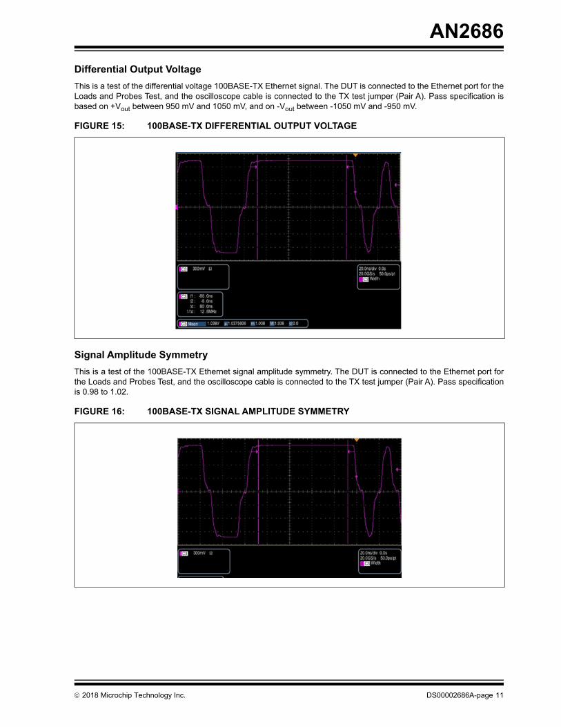
Differential Output Voltage
This is a test of the differential voltage 100BASE-TX Ethernet signal. The DUT is connected to the Ethernet port for theLoads and Probes Test, and the oscilloscope cable is connected to the TX test jumper (Pair A). Pass specification isbased on +Vout between 950 mV and 1050 mV, and on -Vout between -1050 mV and -950 mV.
Signal Amplitude Symmetry
This is a test of the 100BASE-TX Ethernet signal amplitude symmetry. The DUT is connected to the Ethernet port forthe Loads and Probes Test, and the oscilloscope cable is connected to the TX test jumper (Pair A). Pass specificationis 0.98 to 1.02.
FIGURE 15: 100BASE-TX DIFFERENTIAL OUTPUT VOLTAGE
FIGURE 16: 100BASE-TX SIGNAL AMPLITUDE SYMMETRY
2018 Microchip Technology Inc. DS00002686A-page 11
AN2686
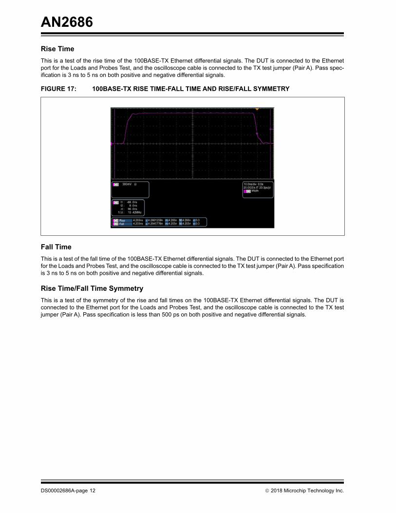
Rise Time
This is a test of the rise time of the 100BASE-TX Ethernet differential signals. The DUT is connected to the Ethernetport for the Loads and Probes Test, and the oscilloscope cable is connected to the TX test jumper (Pair A). Pass spec-ification is 3 ns to 5 ns on both positive and negative differential signals.
Fall Time
This is a test of the fall time of the 100BASE-TX Ethernet differential signals. The DUT is connected to the Ethernet portfor the Loads and Probes Test, and the oscilloscope cable is connected to the TX test jumper (Pair A). Pass specificationis 3 ns to 5 ns on both positive and negative differential signals.
Rise Time/Fall Time Symmetry
This is a test of the symmetry of the rise and fall times on the 100BASE-TX Ethernet differential signals. The DUT isconnected to the Ethernet port for the Loads and Probes Test, and the oscilloscope cable is connected to the TX testjumper (Pair A). Pass specification is less than 500 ps on both positive and negative differential signals.
FIGURE 17: 100BASE-TX RISE TIME-FALL TIME AND RISE/FALL SYMMETRY
DS00002686A-page 12 2018 Microchip Technology Inc.
AN2686
Waveform Overshoot
This is a test of the overshoot of the 100BASE-TX Ethernet signal. The DUT is connected to the Ethernet port for theLoads and Probes Test, and the oscilloscope cable is connected to the TX test jumper (Pair A). Pass specification isless than 5% overshoot on both positive and negative differential signals.
Transmit Jitter
This is a test of the jitter on the 100BASE-TX Ethernet signal. The DUT is connected to the Ethernet port for the Loadsand Probes Test, and the oscilloscope cable is connected to the TX test jumper (Pair A). Pass specification is less than1.4 ns of the jitter.
FIGURE 18: 100BASE-TX WAVEFORM OVERSHOOT
FIGURE 19: 100BASE-TX TRANSMIT JITTER
2018 Microchip Technology Inc. DS00002686A-page 13
AN2686
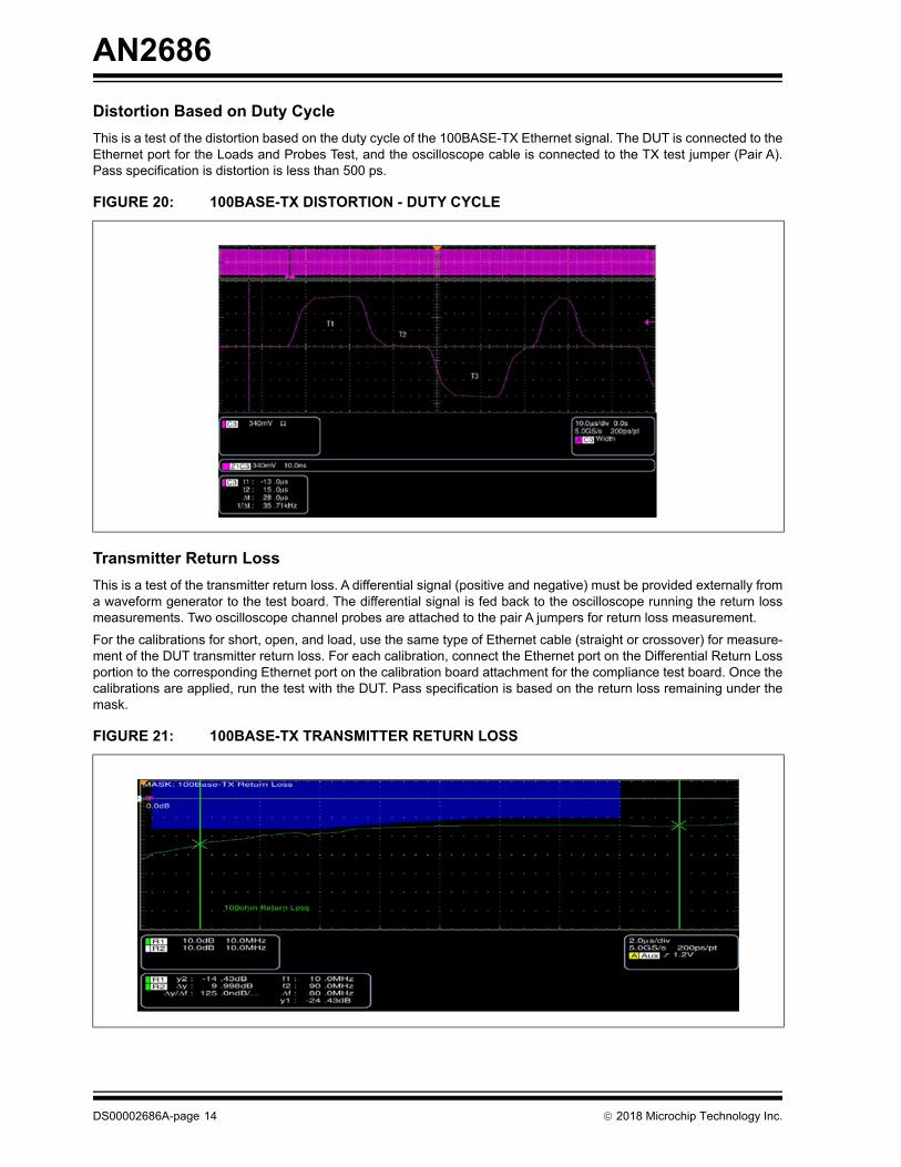
Distortion Based on Duty Cycle
This is a test of the distortion based on the duty cycle of the 100BASE-TX Ethernet signal. The DUT is connected to theEthernet port for the Loads and Probes Test, and the oscilloscope cable is connected to the TX test jumper (Pair A).Pass specification is distortion is less than 500 ps.
Transmitter Return Loss
This is a test of the transmitter return loss. A differential signal (positive and negative) must be provided externally froma waveform generator to the test board. The differential signal is fed back to the oscilloscope running the return lossmeasurements. Two oscilloscope channel probes are attached to the pair A jumpers for return loss measurement.
For the calibrations for short, open, and load, use the same type of Ethernet cable (straight or crossover) for measure-ment of the DUT transmitter return loss. For each calibration, connect the Ethernet port on the Differential Return Lossportion to the corresponding Ethernet port on the calibration board attachment for the compliance test board. Once thecalibrations are applied, run the test with the DUT. Pass specification is based on the return loss remaining under themask.
FIGURE 20: 100BASE-TX DISTORTION - DUTY CYCLE
FIGURE 21: 100BASE-TX TRANSMITTER RETURN LOSS
DS00002686A-page 14 2018 Microchip Technology Inc.
AN2686
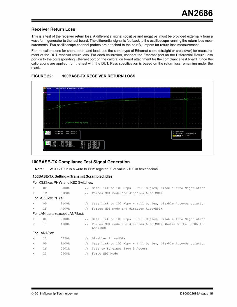
Receiver Return Loss
This is a test of the receiver return loss. A differential signal (positive and negative) must be provided externally from awaveform generator to the test board. The differential signal is fed back to the oscilloscope running the return loss mea-surements. Two oscilloscope channel probes are attached to the pair B jumpers for return loss measurement.
For the calibrations for short, open, and load, use the same type of Ethernet cable (straight or crossover) for measure-ment of the DUT receiver return loss. For each calibration, connect the Ethernet port on the Differential Return Lossportion to the corresponding Ethernet port on the calibration board attachment for the compliance test board. Once thecalibrations are applied, run the test with the DUT. Pass specification is based on the return loss remaining under themask.
100BASE-TX Compliance Test Signal Generation
Note: W 00 2100h is a write to PHY register 00 of value 2100 in hexadecimal.
FIGURE 22: 100BASE-TX RECEIVER RETURN LOSS
100BASE-TX Setting – Transmit Scrambled Idles
For KSZ9xxx PHYs and KSZ Switches:
W 00 2100h // Sets link to 100 Mbps - Full Duplex, Disable Auto-Negotiation
W 1C 00C0h // Forces MDI mode and disables Auto-MDIX
For KSZ8xxx PHYs:
W 00 2100h // Sets link to 100 Mbps - Full Duplex, Disable Auto-Negotiation
W 1F A000h // Forces MDI mode and disables Auto-MDIX
For LAN parts (except LAN78xx):
W 00 2100h // Sets link to 100 Mbps - Full Duplex, Disable Auto-Negotiation
W 11 A000h // Forces MDI mode and disables Auto-MDIX (Note: Write 0020h for LAN7500)
For LAN78xx:
W 12 0020h // Disables Auto-MDIX
W 00 2100h // Sets link to 100 Mbps - Full Duplex, Disable Auto-Negotiation
W 1f 0001h // Sets to Ethernet Page 1 Access
W 13 0008h // Force MDI Mode
2018 Microchip Technology Inc. DS00002686A-page 15
AN2686
1000BASE-T COMPLIANCE TESTING
The 1000BASE-T compliance tests are:
• Peak Differential Output Voltage
• Output Droop
• Template
• Jitter – Master
• Jitter – Slave
• Transmitter Distortion
• Common-Mode Voltage
• Return Loss
Each test must be done for all four Ethernet twisted pairs. The test mode waveforms are found in the Test Mode Tutorialpage of the UNH IOL website, along with all of the points used for Peak Differential Output, Output Droop, and Templatetesting.
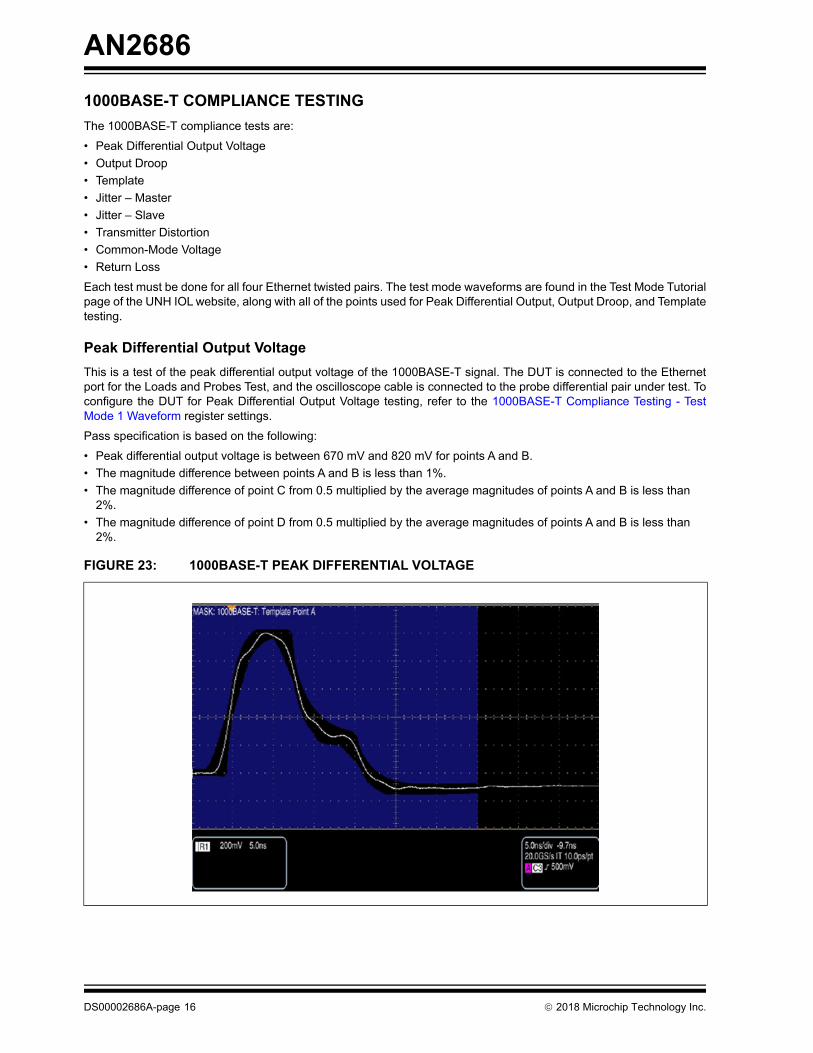
Peak Differential Output Voltage
This is a test of the peak differential output voltage of the 1000BASE-T signal. The DUT is connected to the Ethernetport for the Loads and Probes Test, and the oscilloscope cable is connected to the probe differential pair under test. Toconfigure the DUT for Peak Differential Output Voltage testing, refer to the 1000BASE-T Compliance Testing - TestMode 1 Waveform register settings.
Pass specification is based on the following:
• Peak differential output voltage is between 670 mV and 820 mV for points A and B.
• The magnitude difference between points A and B is less than 1%.
• The magnitude difference of point C from 0.5 multiplied by the average magnitudes of points A and B is less than 2%.
• The magnitude difference of point D from 0.5 multiplied by the average magnitudes of points A and B is less than 2%.
FIGURE 23: 1000BASE-T PEAK DIFFERENTIAL VOLTAGE
DS00002686A-page 16 2018 Microchip Technology Inc.
AN2686
Output Droop
This is a test of the output droop of the 1000BASE-T signal. The DUT is connected to the Ethernet port for the Loadsand Probes Test, and the oscilloscope cable is connected to the probe differential pair under test. To configure the DUTfor Output Droop testing, refer to the 1000BASE-T Compliance Testing - Test Mode 1 Waveform register settings.
Pass specification is based on the following:
• The magnitude at point G is greater than 73.1% the magnitude at point F.
• The magnitude at point J is greater than 73.1% the magnitude at point H.
FIGURE 24: 1000BASE-T OUTPUT DROOP - POINT G
FIGURE 25: 1000BASE-T OUTPUT DROOP - POINT J
2018 Microchip Technology Inc. DS00002686A-page 17
AN2686
Template Tests
This is a test of the voltage points for the test mode 1 1000BASE-T waveform using templates for each voltage point.The DUT is connected to the Ethernet port for the Loads and Probes Test, and the oscilloscope cable is connected tothe probe differential pair under test. To configure the DUT for 1000BASE-T Template testing, refer to the 1000BASE-T Compliance Testing - Test Mode 1 Waveform register settings. Pass specification is for all templates to fall within themask allowed for voltage points A, B, C, D, F, and H. See Figure 23 for reference.
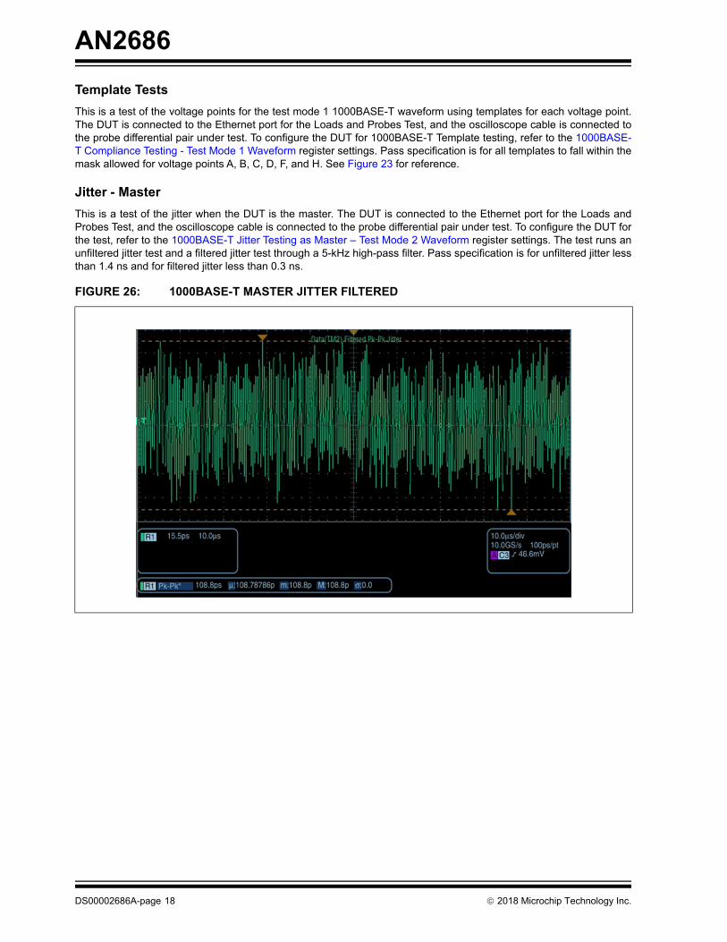
Jitter - Master
This is a test of the jitter when the DUT is the master. The DUT is connected to the Ethernet port for the Loads andProbes Test, and the oscilloscope cable is connected to the probe differential pair under test. To configure the DUT forthe test, refer to the 1000BASE-T Jitter Testing as Master – Test Mode 2 Waveform register settings. The test runs anunfiltered jitter test and a filtered jitter test through a 5-kHz high-pass filter. Pass specification is for unfiltered jitter lessthan 1.4 ns and for filtered jitter less than 0.3 ns.
FIGURE 26: 1000BASE-T MASTER JITTER FILTERED
DS00002686A-page 18 2018 Microchip Technology Inc.
AN2686
Jitter - Slave
This is a test of the jitter when the DUT is the slave. The DUT is connected to the Ethernet port for the Loads and ProbesTest, and the oscilloscope cable is connected to the probe differential pair under test. To configure the DUT for the test,refer to the 1000BASE-T Jitter Testing as Master – Test Mode 2 Waveform register settings for the first part and to the1000BASE-T Jitter Testing as Slave – Test Mode 3 Waveform register settings for the second part. The test runs anunfiltered jitter test and a filtered jitter test through a 5-kHz high-pass filter. Pass specification is for unfiltered jitter lessthan 1.4 ns and for filtered jitter less than 0.4 ns.
FIGURE 27: 1000BASE-T SLAVE JITTER FILTERED
2018 Microchip Technology Inc. DS00002686A-page 19
AN2686
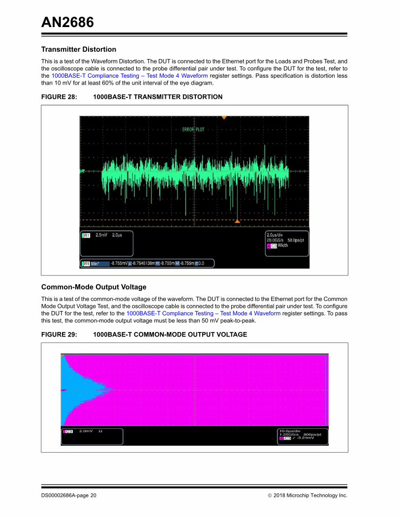
Transmitter Distortion
This is a test of the Waveform Distortion. The DUT is connected to the Ethernet port for the Loads and Probes Test, andthe oscilloscope cable is connected to the probe differential pair under test. To configure the DUT for the test, refer tothe 1000BASE-T Compliance Testing – Test Mode 4 Waveform register settings. Pass specification is distortion lessthan 10 mV for at least 60% of the unit interval of the eye diagram.
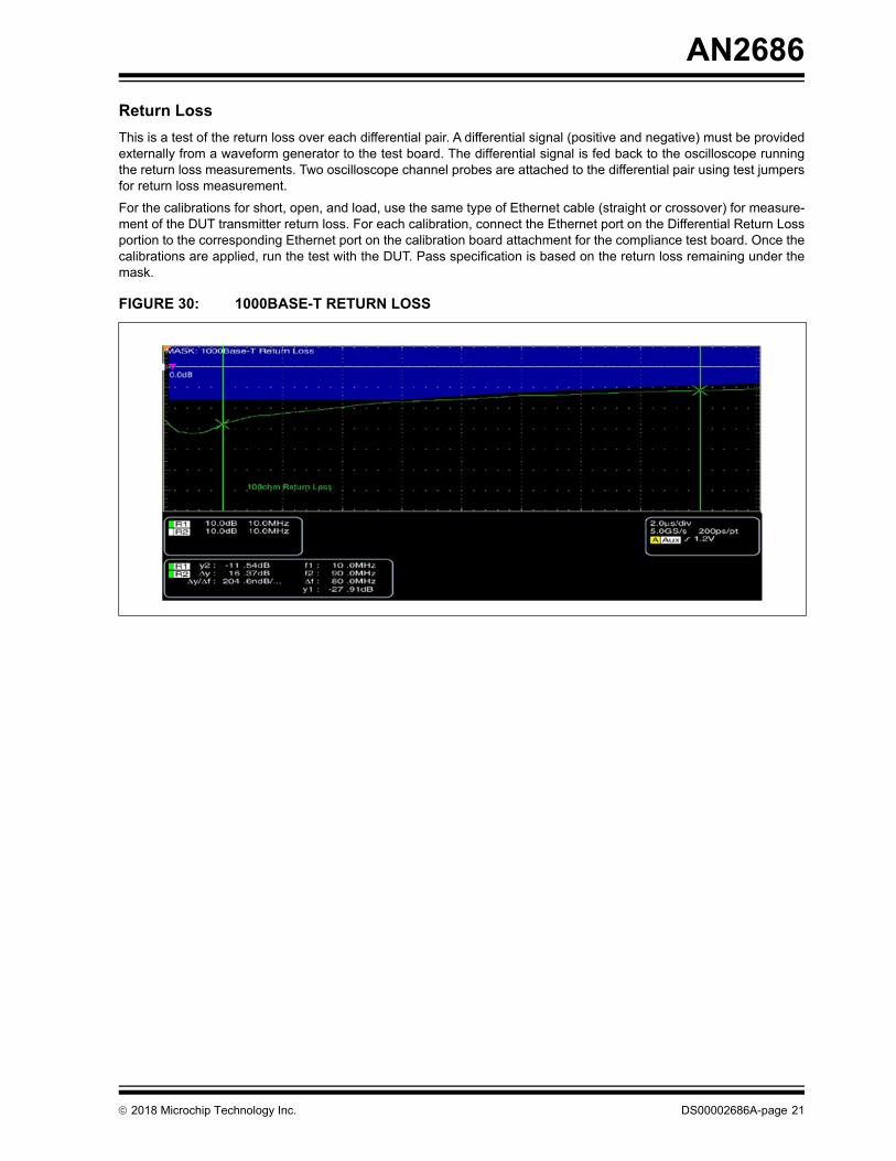
Common-Mode Output Voltage
This is a test of the common-mode voltage of the waveform. The DUT is connected to the Ethernet port for the CommonMode Output Voltage Test, and the oscilloscope cable is connected to the probe differential pair under test. To configurethe DUT for the test, refer to the 1000BASE-T Compliance Testing – Test Mode 4 Waveform register settings. To passthis test, the common-mode output voltage must be less than 50 mV peak-to-peak.
FIGURE 28: 1000BASE-T TRANSMITTER DISTORTION
FIGURE 29: 1000BASE-T COMMON-MODE OUTPUT VOLTAGE
DS00002686A-page 20 2018 Microchip Technology Inc.
AN2686
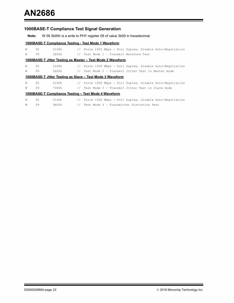
Return Loss
This is a test of the return loss over each differential pair. A differential signal (positive and negative) must be providedexternally from a waveform generator to the test board. The differential signal is fed back to the oscilloscope runningthe return loss measurements. Two oscilloscope channel probes are attached to the differential pair using test jumpersfor return loss measurement.
For the calibrations for short, open, and load, use the same type of Ethernet cable (straight or crossover) for measure-ment of the DUT transmitter return loss. For each calibration, connect the Ethernet port on the Differential Return Lossportion to the corresponding Ethernet port on the calibration board attachment for the compliance test board. Once thecalibrations are applied, run the test with the DUT. Pass specification is based on the return loss remaining under themask.
FIGURE 30: 1000BASE-T RETURN LOSS
2018 Microchip Technology Inc. DS00002686A-page 21
AN2686
1000BASE-T Compliance Test Signal Generation
Note: W 09 3b00h is a write to PHY register 09 of value 3b00 in hexadecimal.
1000BASE-T Compliance Testing - Test Mode 1 Waveform
W 00 0140h // Force 1000 Mbps - Full Duplex, Disable Auto-Negotiation
W 09 3b00h // Test Mode 1 – Transmit Waveform Test
1000BASE-T Jitter Testing as Master – Test Mode 2 Waveform
W 00 0140h // Force 1000 Mbps - Full Duplex, Disable Auto-Negotiation
W 09 5b00h // Test Mode 2 – Transmit Jitter Test in Master mode
1000BASE-T Jitter Testing as Slave – Test Mode 3 Waveform
W 00 0140h // Force 1000 Mbps - Full Duplex, Disable Auto-Negotiation
W 09 7300h // Test Mode 3 – Transmit Jitter Test in Slave mode
1000BASE-T Compliance Testing – Test Mode 4 Waveform
W 00 0140h // Force 1000 Mbps - Full Duplex, Disable Auto-Negotiation
W 09 9b00h // Test Mode 4 – Transmitter Distortion Test
DS00002686A-page 22 2018 Microchip Technology Inc.
2018 Microchip Technology Inc. DS00002686A-page 23
AN2686
APPENDIX A: REVISION HISTORY
TABLE A-1: REVISION HISTORY
Revision Section/Figure/Entry Correction
DS00002686A (04-10-18)
Initial release
AN2686
DS00002686A-page 24 2018 Microchip Technology Inc.
THE MICROCHIP WEB SITE
Microchip provides online support via our WWW site at www.microchip.com. This web site is used as a means to makefiles and information easily available to customers. Accessible by using your favorite Internet browser, the web sitecontains the following information:
• Product Support – Data sheets and errata, application notes and sample programs, design resources, user’s guides and hardware support documents, latest software releases and archived software
• General Technical Support – Frequently Asked Questions (FAQ), technical support requests, online discussion groups, Microchip consultant program member listing
• Business of Microchip – Product selector and ordering guides, latest Microchip press releases, listing of seminars and events, listings of Microchip sales offices, distributors and factory representatives
CUSTOMER CHANGE NOTIFICATION SERVICE
Microchip’s customer notification service helps keep customers current on Microchip products. Subscribers will receivee-mail notification whenever there are changes, updates, revisions or errata related to a specified product family ordevelopment tool of interest.
To register, access the Microchip web site at www.microchip.com. Under “Support”, click on “Customer Change Notifi-cation” and follow the registration instructions.
CUSTOMER SUPPORT
Users of Microchip products can receive assistance through several channels:
• Distributor or Representative
• Local Sales Office
• Field Application Engineer (FAE)
• Technical Support
Customers should contact their distributor, representative or Field Application Engineer (FAE) for support. Local salesoffices are also available to help customers. A listing of sales offices and locations is included in the back of thisdocument.
Technical support is available through the web site at: http://microchip.com/support
2018 Microchip Technology Inc. DS00002686A-page 25
Information contained in this publication regarding device applications and the like is provided only for your convenience and may besuperseded by updates. It is your responsibility to ensure that your application meets with your specifications. MICROCHIP MAKES NOREPRESENTATIONS OR WARRANTIES OF ANY KIND WHETHER EXPRESS OR IMPLIED, WRITTEN OR ORAL, STATUTORY OROTHERWISE, RELATED TO THE INFORMATION, INCLUDING BUT NOT LIMITED TO ITS CONDITION, QUALITY, PERFORMANCE,MERCHANTABILITY OR FITNESS FOR PURPOSE. Microchip disclaims all liability arising from this information and its use. Use ofMicrochip devices in life support and/or safety applications is entirely at the buyer’s risk, and the buyer agrees to defend, indemnify andhold harmless Microchip from any and all damages, claims, suits, or expenses resulting from such use. No licenses are conveyed, implic-itly or otherwise, under any Microchip intellectual property rights unless otherwise stated.
Trademarks
The Microchip name and logo, the Microchip logo, AnyRate, AVR, AVR logo, AVR Freaks, BeaconThings, BitCloud, CryptoMemory, CryptoRF, dsPIC, FlashFlex, flexPWR, Heldo, JukeBlox, KEELOQ, KEELOQ logo, Kleer, LANCheck, LINK MD, maXStylus, maXTouch, MediaLB, megaAVR, MOST, MOST logo, MPLAB, OptoLyzer, PIC, picoPower, PICSTART, PIC32 logo, Prochip Designer, QTouch, RightTouch, SAM-BA, SpyNIC, SST, SST Logo, SuperFlash, tinyAVR, UNI/O, and XMEGA are registered trademarks of Microchip Technology Incorporated in the U.S.A. and other countries.
ClockWorks, The Embedded Control Solutions Company, EtherSynch, Hyper Speed Control, HyperLight Load, IntelliMOS, mTouch, Precision Edge, and Quiet-Wire are registered trademarks of Microchip Technology Incorporated in the U.S.A.
Adjacent Key Suppression, AKS, Analog-for-the-Digital Age, Any Capacitor, AnyIn, AnyOut, BodyCom, chipKIT, chipKIT logo, CodeGuard, CryptoAuthentication, CryptoCompanion, CryptoController, dsPICDEM, dsPICDEM.net, Dynamic Average Matching, DAM, ECAN, EtherGREEN, In-Circuit Serial Programming, ICSP, Inter-Chip Connectivity, JitterBlocker, KleerNet, KleerNet logo, Mindi, MiWi, motorBench, MPASM, MPF, MPLAB Certified logo, MPLIB, MPLINK, MultiTRAK, NetDetach, Omniscient Code Generation, PICDEM, PICDEM.net, PICkit, PICtail, PureSilicon, QMatrix, RightTouch logo, REAL ICE, Ripple Blocker, SAM-ICE, Serial Quad I/O, SMART-I.S., SQI, SuperSwitcher, SuperSwitcher II, Total Endurance, TSHARC, USBCheck, VariSense, ViewSpan, WiperLock, Wireless DNA, and ZENA are trademarks of Microchip Technology Incorporated in the U.S.A. and other countries.
SQTP is a service mark of Microchip Technology Incorporated in the U.S.A.
Silicon Storage Technology is a registered trademark of Microchip Technology Inc. in other countries.
GestIC is a registered trademark of Microchip Technology Germany II GmbH & Co. KG, a subsidiary of Microchip Technology Inc., in other countries.
All other trademarks mentioned herein are property of their respective companies.
Note the following details of the code protection feature on Microchip devices:
• Microchip products meet the specification contained in their particular Microchip Data Sheet.
• Microchip believes that its family of products is one of the most secure families of its kind on the market today, when used in the intended manner and under normal conditions.
• There are dishonest and possibly illegal methods used to breach the code protection feature. All of these methods, to our knowledge, require using the Microchip products in a manner outside the operating specifications contained in Microchip’s Data Sheets. Most likely, the person doing so is engaged in theft of intellectual property.
• Microchip is willing to work with the customer who is concerned about the integrity of their code.
• Neither Microchip nor any other semiconductor manufacturer can guarantee the security of their code. Code protection does not mean that we are guaranteeing the product as “unbreakable.”
Code protection is constantly evolving. We at Microchip are committed to continuously improving the code protection features of ourproducts. Attempts to break Microchip’s code protection feature may be a violation of the Digital Millennium Copyright Act. If such actsallow unauthorized access to your software or other copyrighted work, you may have a right to sue for relief under that Act.
Microchip received ISO/TS-16949:2009 certification for its worldwide headquarters, design and wafer fabrication facilities in Chandler and Tempe, Arizona; Gresham, Oregon and design centers in California and India. The Company’s quality system processes and procedures are for its PIC® MCUs and dsPIC® DSCs, KEELOQ® code hopping devices, Serial EEPROMs, microperipherals, nonvolatile memory and analog products. In addition, Microchip’s quality system for the design and manufacture of development systems is ISO 9001:2000 certified.
QUALITYMANAGEMENTSYSTEMCERTIFIEDBYDNV
== ISO/TS16949==
DS00002686A-page 26 2018 Microchip Technology Inc.
AMERICASCorporate Office2355 West Chandler Blvd.Chandler, AZ 85224-6199Tel: 480-792-7200 Fax: 480-792-7277Technical Support: http://www.microchip.com/supportWeb Address: www.microchip.com
AtlantaDuluth, GA Tel: 678-957-9614 Fax: 678-957-1455
Austin, TXTel: 512-257-3370
BostonWestborough, MA Tel: 774-760-0087 Fax: 774-760-0088
ChicagoItasca, IL Tel: 630-285-0071 Fax: 630-285-0075