November 2019 AN3156 Rev 11 1/22 AN3156 Application note USB DFU protocol used in the STM32 bootloader Introduction This application note describes the USB DFU protocol used in STM32 microcontroller bootloader, detailing each supported command. This document applies to the STM32 products embedding bootloader versions V3.x, V4.x, V7.x, V9.x, V10.x and V13.x as specified in AN2606 “STM32 microcontroller system memory boot mode” (available on www.st.com), which also contains more information about the USB hardware resources and requirements for the device bootloader. These products are listed in Table 1, and are referred to as STM32 throughout the document. Table 1. Applicable products Type Series Microcontrollers STM32F0 Series STM32F1 Series STM32F2 Series STM32F3 Series STM32F4 Series STM32F7 Series STM32G0 Series STM32G4 Series STM32H7 Series STM32L0 Series STM32L1 Series STM32L4 Series STM32L5 Series STM32WB Series www.st.com
Transcript
November 2019 AN3156 Rev 11 1/22
AN3156Application note
USB DFU protocol used in the STM32 bootloader
Introduction
This application note describes the USB DFU protocol used in STM32 microcontroller bootloader, detailing each supported command.
This document applies to the STM32 products embedding bootloader versions V3.x, V4.x, V7.x, V9.x, V10.x and V13.x as specified in AN2606 “STM32 microcontroller system memory boot mode” (available on www.st.com), which also contains more information about the USB hardware resources and requirements for the device bootloader. These products are listed in Table 1, and are referred to as STM32 throughout the document.
There is no difference in terms of protocol (requests and commands) between different bootloader DFU versions. For the detailed difference list refer to Section 6.
Once the system memory boot mode is entered and the STM32 microcontroller (based on on Arm®(a) cores) has been configured (for more details refer to AN2606), the bootloader code configures the USB and its interrupts, and waits for the “enumeration done” interrupt.
The USB enumeration is performed as soon as the USB cable is plugged (or immediately if the cable is already plugged). If the user does not want the STM32 to enter the USB DFU bootloader application, the USB cable has to be unplugged before reset.
The bootloader version is returned in the device descriptor in the MSB of the bcd Device field (example: 0x2000 = Version 2.0).
For connectivity line USB DFU bootloader, the device first tries the 25 MHz configuration, then, if it fails, the 14.7456 MHz configuration, and finally, if it fails, the 8 MHz configuration. In case of fail, this operation is repeated with a bigger timeout value (the three configurations are tested again). If the second trial fails, a system reset is generated.
a. Arm is a registered trademark of Arm Limited (or its subsidiaries) in the US and/or elsewhere.
Bootloader code sequence AN3156
6/22 AN3156 Rev 11
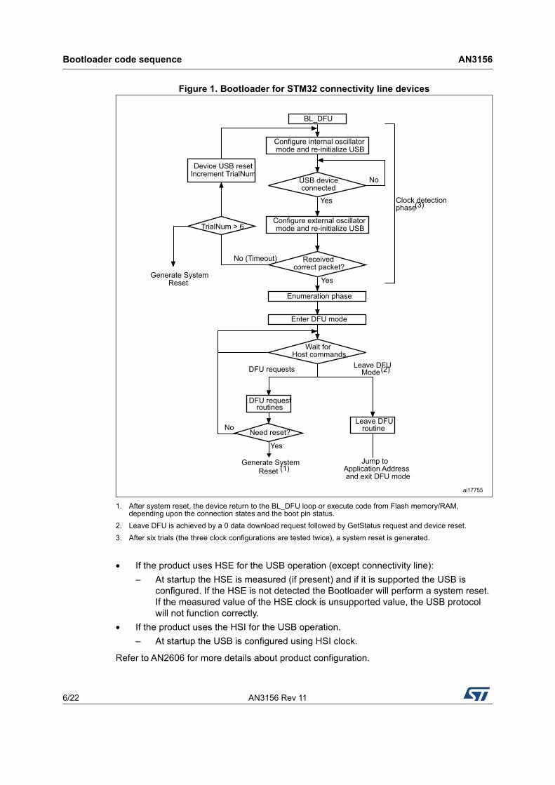
Figure 1. Bootloader for STM32 connectivity line devices
1. After system reset, the device return to the BL_DFU loop or execute code from Flash memory/RAM, depending upon the connection states and the boot pin status.
2. Leave DFU is achieved by a 0 data download request followed by GetStatus request and device reset.
3. After six trials (the three clock configurations are tested twice), a system reset is generated.
• If the product uses HSE for the USB operation (except connectivity line):
– At startup the HSE is measured (if present) and if it is supported the USB is configured. If the HSE is not detected the Bootloader will perform a system reset. If the measured value of the HSE clock is unsupported value, the USB protocol will not function correctly.
• If the product uses the HSI for the USB operation.
– At startup the USB is configured using HSI clock.
Refer to AN2606 for more details about product configuration.
BL_DFU
Receivedcorrect packet?
No (Timeout)
Yes
Configure external oscillator mode and re-initialize USB
Enumeration phase
Enter DFU mode
Wait forHost commands
DFU requestroutines
DFU requests
Jump to
Leave DFUroutine
Leave DFU
Generate System
and exit DFU mode
Need reset?
Reset (1) Application Address
Yes
No
Mode (2)
Configure internal oscillator mode and re-initialize USB
USB deviceconnected
No
Yes
Device USB reset
Clock detectionphase(3)
Increment TrialNum
TrialNum > 6
Generate SystemReset
ai17755
AN3156 Rev 11 7/22
AN3156 Bootloader code sequence
21
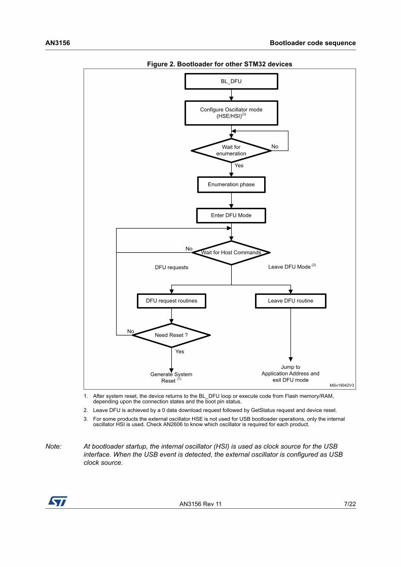
Figure 2. Bootloader for other STM32 devices
1. After system reset, the device returns to the BL_DFU loop or execute code from Flash memory/RAM, depending upon the connection states and the boot pin status.
2. Leave DFU is achieved by a 0 data download request followed by GetStatus request and device reset.
3. For some products the external oscillator HSE is not used for USB bootloader operations, only the internal oscillator HSI is used. Check AN2606 to know which oscillator is required for each product.
Note: At bootloader startup, the internal oscillator (HSI) is used as clock source for the USB interface. When the USB event is detected, the external oscillator is configured as USB clock source.
MSv19042V3
BL_DFU
Wait for enumeration
No
Yes
Configure Oscillator mode(HSE/HSI)(3)
Enumeration phase
Enter DFU Mode
Generate System Reset (1)
Wait for Host Commands
DFU request routines
Yes
Need Reset ?
Leave DFU routine
Jump to Application Address and
exit DFU mode
DFU requests Leave DFU Mode (2)
No
No
USB DFU bootloader requests AN3156
8/22 AN3156 Rev 11
2 USB DFU bootloader requests
USB DFU bootloader supports the DFU protocol and requests compliant with the “Universal Serial Bus Device Upgrade Specification for Device Firmware Upgrade” Version 1.1, Aug 5, 2004. For more details concerning these requests, refer to the specification.
Table 2 and Table 3 enumerate the DFU class-specific requests and their parameters.
Note: The Detach request is not meaningful in the case of the bootloader. The bootloader is started by a system reset depending on the boot mode configuration settings, which means that no other application is running at that time.
Communication safety
The communication between host and device is secured by the embedded USB protection mechanisms (e.g. CRC checking, acknowledgements). No further protection is performed for transferred data or for bootloader specific commands/data.
Table 2. DFU class requests
Request Code Description
DFU_DETACH 0x00 Requests the device to leave DFU mode and enter the application.
DFU_DNLOAD 0x01Requests data transfer from Host to the device in order to load them into device internal Flash memory. Includes also erase commands.
DFU_UPLOAD 0x02Requests data transfer from device to Host in order to load content of device internal Flash memory into a Host file.
DFU_GETSTATUS 0x03Requests device to send status report to the Host (including status resulting from the last request execution and the state the device will enter immediately after this request).
DFU_CLRSTATUS 0x04 Requests device to clear error status and move to next step.
DFU_GETSTATE 0x05Requests the device to send only the state it will enter immediately after this request.
DFU_ABORT 0x06Requests device to exit the current state/operation and enter idle state immediately.
10100001b DFU_UPLOAD Zero Interface Length Firmware
00100001b DFU_GETSTATUS Zero Interface 6 Status
00100001b DFU_CLRSTATUS Zero Interface Zero None
00100001b DFU_GETSTATE Zero Interface 1 State
00100001b DFU_ABORT Zero Interface Zero None
AN3156 Rev 11 9/22
AN3156 DFU bootloader commands
21
3 DFU bootloader commands
The DFU_DNLOAD and DFU_UPLOAD requests are mainly used to perform simple write and read memory operations. They are also used to initiate the integrated bootloader commands (such as Write, Read Unprotect, Erase, Set Address). The DFU_GETSTATUS command then triggers the command execution.
In the DFU download request the command is selected through the wValue parameter in the USB request structure. If wValue = 0 then the data sent by the host after the request is a bootloader command code. The first byte is the command code and the other bytes (if any) are the data related to this command.
In the DFU upload request the command is selected through the wValue parameter in the USB request structure. If wValue = 0 then Get Command is selected and performed.
If the user performs a Read Unprotect operation while the memory is not protected, the whole RAM is cleared by the bootloader firmware and the Flash memory is not erased (since it was not previously read-protected).
There are no commands for the Write Protect, Write Unprotect and Read Protect operations. These operations can be performed through the Write Memory and Read Memory commands used for the option byte area.
Table 4. DFU bootloader commands
DFU requestBootloader command
Write protection disabled
Read protection disabled
Write protection enabled
Read protection disabled
Read protection enabled
DFU_UPLOADRead Memory Allowed Allowed Not allowed
Get Allowed Allowed Allowed
DFU_DNLOAD
Write Memory Allowed Allowed(1)
1. This operation is allowed but not effective: the bootloader does not return an error but the operation is not executed since the sectors are write-protected. This applies only to the Flash memory. It does not apply to the RAM or to the option byte area.
Not allowed
Erase Allowed Allowed(1) Not allowed
Read Unprotect N/A(2)
2. Not applicable (this operation is allowed but has no meaning since the memory is not protected).
N/A(2) Allowed(3)
3. In this case, both the Flash memory (from 0x0800 0000) and the RAM are erased. The option byte area is reset to default values.
Set Address Pointer Allowed Allowed Allowed
Leave DFU mode Allowed Allowed Allowed
DFU_UPLOAD request commands AN3156
10/22 AN3156 Rev 11
4 DFU_UPLOAD request commands
The upload request enables the execution of different commands, their selection is done through the value of parameter wValue in the USB request structure. The supported operations are described in Sections 4.1 to 5.5.
4.1 Read memory
The Read memory operation is selected when wValue > 1.
The host requests the device to send a specified number of data bytes (wLength) from valid memory address (see note) of the internal Flash memory, embedded RAM, system memory or from the option bytes.
Note: Refer to Section 4 for more details about the valid memory addresses for the used device.
The allowed number of bytes to be read depends on the memory target:
• for the internal Flash memory, embedded RAM and system memory read size can be from 2 to 2048 bytes
• for the option bytes read size has to be equal to the option byte block size
• for other memory locations, refer to AN2606.
The address from which the host requests to read data is computed using the value of wBlockNumber (wValue) and the address pointer according to the following formula:
– wTransferSize is the length of the requested data buffer.
The address pointer must be previously specified through a Set Address Pointer command (using a DFU_DNLOAD request), otherwise (if no address was previously specified) the device assumes that it is the internal Flash memory start address (0x08000000).
If the Flash memory read protection is enabled, the read operation is not performed and the returned device status is (Status = dfuERROR, State = errVENDOR) whatever the target (internal Flash memory, embedded RAM, system memory or option bytes).
4.2 Get command
This command is selected when wValue = 0.
The host requests to read the commands supported by the bootloader. After receiving this command, the device returns N bytes representing the command codes.
The STM32 sends bytes as follows (N = 4):
The processing of the DFU_UPLOAD command is shown in Figure 3 and Figure 4.
Byte 1: 0x00 Get command
Byte 2: 0x21 Set Address Pointer
Byte 3: 0x41 Erase
Byte 4: 0x92 Read Unprotect
AN3156 Rev 11 11/22
AN3156 DFU_UPLOAD request commands
21
Figure 3. DFU_UPLOAD request: device side
Figure 4. DFU_UPLOAD request: host side
Note: Before issuing an Upload request, the host has to check that the device is in a correct state (dfuIDLE or dfuUPLOAD-IDLE state) and that there is no error reported in the status. If the device is not in the required state, the host has to clear any error (DFU_CLRSTATUS request) and get the new status until the device returns to dfuIDLE state.
DFU_UPLOAD request
No
Yes
Send the supported
wBlockNum == 0?
ROP Active?No
Yes
Status = errVENDORSend the requested
number of data bytes
No
Yes
wBlockNum > 1?
command codes
Stall
State = dfuERROR
Current status is dfuIDLE or dfuUPLOAD-IDLE
Stall
No
Acknowledgethe request
Yes
ai17756
MS53178V1
Requestacknowledged?
DFU_UPLOAD request
Read the requested number of data bytes
Get device status
Status=errVENDOR?
Error Read protection is active
No
NoYes
Yes
DFU_DNLOAD request commands AN3156
12/22 AN3156 Rev 11
5 DFU_DNLOAD request commands
The download request is used to perform different commands. The command selection is done through the value of parameter wValue in the USB request structure. The following operations are supported:
• Write Memory (wValue > 1)
• Set Address Pointer (wValue = 0 and first byte = 0x21)
• Erase (wValue = 0 and first byte = 0x41)
• Read Unprotect (wValue = 0 and first byte = 0x92)
• Leave DFU (leave DFU mode and jump to application)
Figure 5. Download request: device side
1. This routine can be used to reset the device or to jump to the application.
MS53179V1
Download request
Erasecommand
Set Address
No
Yes
Decode the command(first byte of the received buffer)
Set Address Pointer routine
Read Unprotect
wBlockNum = 0?
Pointer commandUnsupportedcommand
Erase routine
State = dfuERRORStatus = errSTALLEDPKT
Read Unprotectroutine
command
Write Memoryroutine
No
Yes
wBlockNum > 1?
Stall
Wait for data stage ?
Return Status: dfuDNBUSY
Current staus is dfuIDLEor dfuDNLOAD-IDLE?
Stall
No
Acknowledgethe request
Yes
Receive data buffer
Wait for Get Status?
wLength > 0 ?
Yes
No
Leave DFUroutine (1)
Yes
No
Yes
No
AN3156 Rev 11 13/22
AN3156 DFU_DNLOAD request commands
21
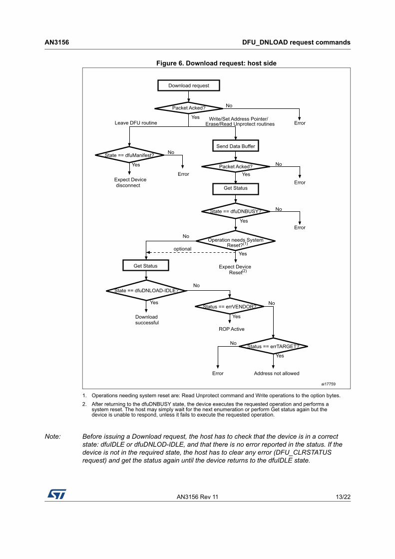
Figure 6. Download request: host side
1. Operations needing system reset are: Read Unprotect command and Write operations to the option bytes.
2. After returning to the dfuDNBUSY state, the device executes the requested operation and performs a system reset. The host may simply wait for the next enumeration or perform Get status again but the device is unable to respond, unless it fails to execute the requested operation.
Note: Before issuing a Download request, the host has to check that the device is in a correct state: dfuIDLE or dfuDNLOD-IDLE, and that there is no error reported in the status. If the device is not in the required state, the host has to clear any error (DFU_CLRSTATUS request) and get the status again until the device returns to the dfuIDLE state.
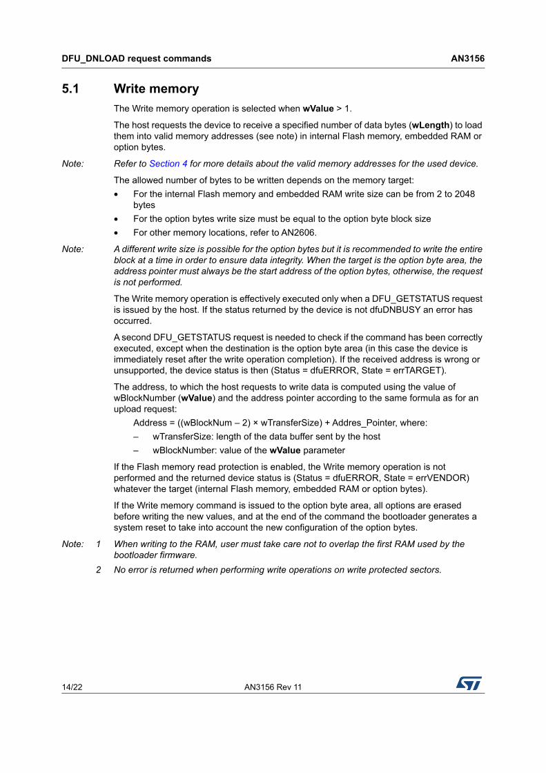
The Write memory operation is selected when wValue > 1.
The host requests the device to receive a specified number of data bytes (wLength) to load them into valid memory addresses (see note) in internal Flash memory, embedded RAM or option bytes.
Note: Refer to Section 4 for more details about the valid memory addresses for the used device.
The allowed number of bytes to be written depends on the memory target:
• For the internal Flash memory and embedded RAM write size can be from 2 to 2048 bytes
• For the option bytes write size must be equal to the option byte block size
• For other memory locations, refer to AN2606.
Note: A different write size is possible for the option bytes but it is recommended to write the entire block at a time in order to ensure data integrity. When the target is the option byte area, the address pointer must always be the start address of the option bytes, otherwise, the request is not performed.
The Write memory operation is effectively executed only when a DFU_GETSTATUS request is issued by the host. If the status returned by the device is not dfuDNBUSY an error has occurred.
A second DFU_GETSTATUS request is needed to check if the command has been correctly executed, except when the destination is the option byte area (in this case the device is immediately reset after the write operation completion). If the received address is wrong or unsupported, the device status is then (Status = dfuERROR, State = errTARGET).
The address, to which the host requests to write data is computed using the value of wBlockNumber (wValue) and the address pointer according to the same formula as for an upload request:
– wTransferSize: length of the data buffer sent by the host
– wBlockNumber: value of the wValue parameter
If the Flash memory read protection is enabled, the Write memory operation is not performed and the returned device status is (Status = dfuERROR, State = errVENDOR) whatever the target (internal Flash memory, embedded RAM or option bytes).
If the Write memory command is issued to the option byte area, all options are erased before writing the new values, and at the end of the command the bootloader generates a system reset to take into account the new configuration of the option bytes.
Note: 1 When writing to the RAM, user must take care not to overlap the first RAM used by the bootloader firmware.
2 No error is returned when performing write operations on write protected sectors.
AN3156 Rev 11 15/22
AN3156 DFU_DNLOAD request commands
21
Figure 7. Write memory: device side
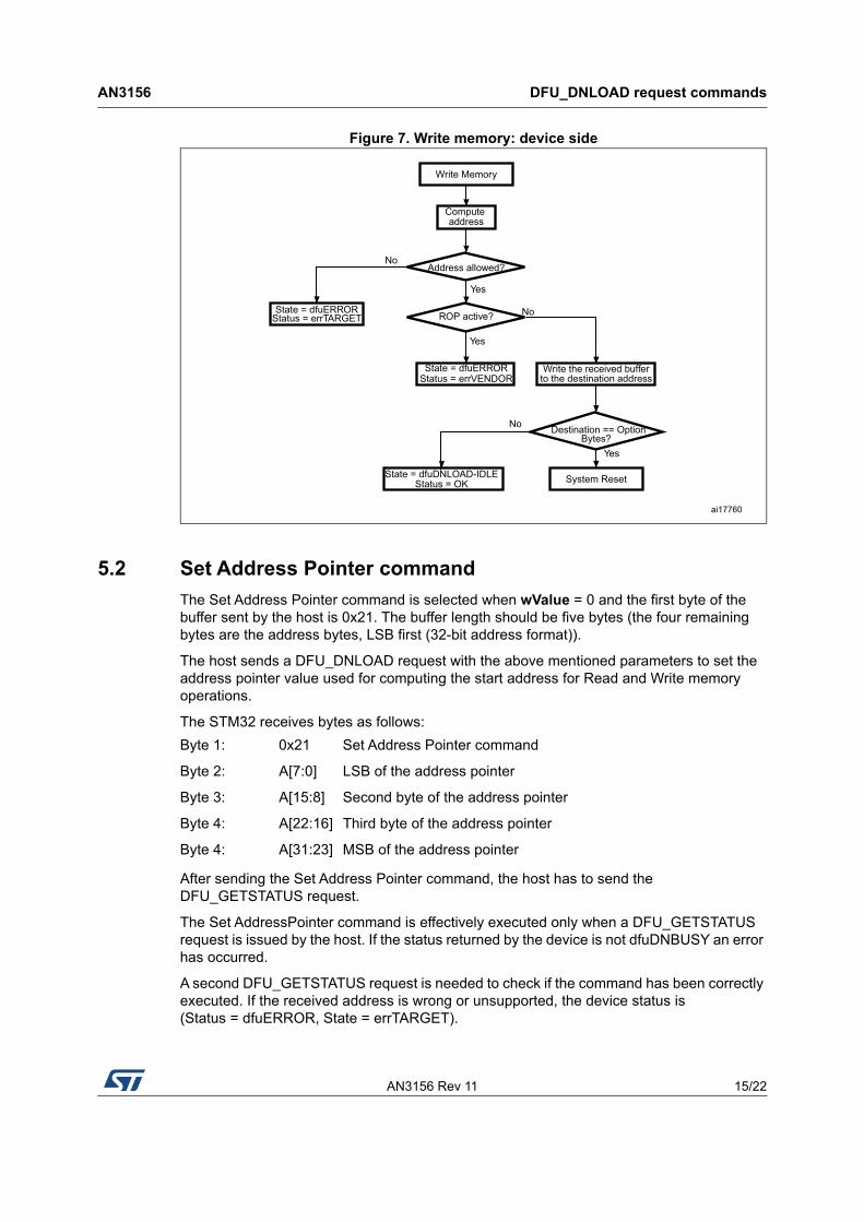
5.2 Set Address Pointer command
The Set Address Pointer command is selected when wValue = 0 and the first byte of the buffer sent by the host is 0x21. The buffer length should be five bytes (the four remaining bytes are the address bytes, LSB first (32-bit address format)).
The host sends a DFU_DNLOAD request with the above mentioned parameters to set the address pointer value used for computing the start address for Read and Write memory operations.
The STM32 receives bytes as follows:
After sending the Set Address Pointer command, the host has to send the DFU_GETSTATUS request.
The Set AddressPointer command is effectively executed only when a DFU_GETSTATUS request is issued by the host. If the status returned by the device is not dfuDNBUSY an error has occurred.
A second DFU_GETSTATUS request is needed to check if the command has been correctly executed. If the received address is wrong or unsupported, the device status is (Status = dfuERROR, State = errTARGET).
Write Memory
No
Yes
Write the received bufferto the destination address
Address allowed?
ROP active?
Yes
No
State = dfuERRORStatus = errVENDOR
Compute address
State = dfuERRORStatus = errTARGET
State = dfuDNLOAD-IDLEStatus = OK
No
Yes
Destination == OptionBytes?
System Reset
ai17760
Byte 1: 0x21 Set Address Pointer command
Byte 2: A[7:0] LSB of the address pointer
Byte 3: A[15:8] Second byte of the address pointer
Byte 4: A[22:16] Third byte of the address pointer
Byte 4: A[31:23] MSB of the address pointer
DFU_DNLOAD request commands AN3156
16/22 AN3156 Rev 11
The allowed locations for address pointer values are valid memory addresses in the internal Flash memory, embedded RAM, system memory and option bytes.
Note: 1 Refer to Section 4 for more details about the valid memory addresses for the used device.
2 The Set Address Pointer command is allowed and executed when the Flash memory read protection is enabled or disabled.
Figure 8. Set Address Pointer command: device side
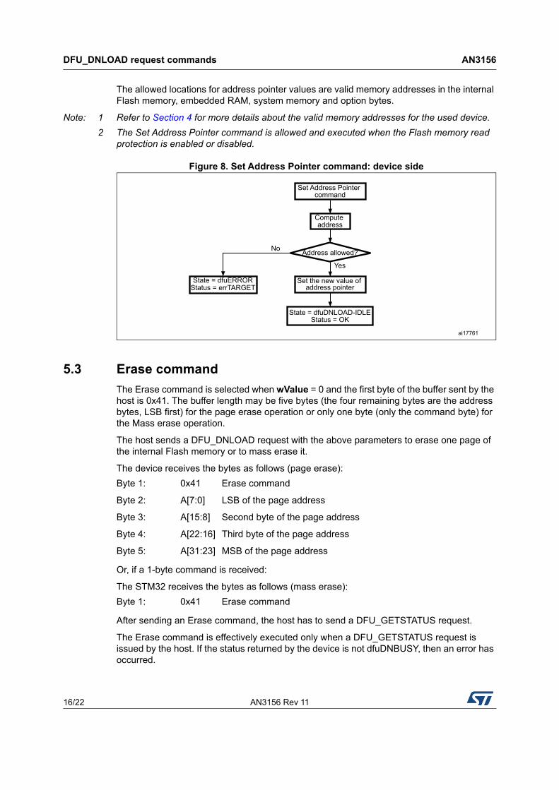
5.3 Erase command
The Erase command is selected when wValue = 0 and the first byte of the buffer sent by the host is 0x41. The buffer length may be five bytes (the four remaining bytes are the address bytes, LSB first) for the page erase operation or only one byte (only the command byte) for the Mass erase operation.
The host sends a DFU_DNLOAD request with the above parameters to erase one page of the internal Flash memory or to mass erase it.
The device receives the bytes as follows (page erase):
Or, if a 1-byte command is received:
The STM32 receives the bytes as follows (mass erase):
After sending an Erase command, the host has to send a DFU_GETSTATUS request.
The Erase command is effectively executed only when a DFU_GETSTATUS request is issued by the host. If the status returned by the device is not dfuDNBUSY, then an error has occurred.
Set Address Pointer command
No
Yes
Set the new value of address pointer
Address allowed?
Compute address
State = dfuERRORStatus = errTARGET
State = dfuDNLOAD-IDLEStatus = OK
ai17761
Byte 1: 0x41 Erase command
Byte 2: A[7:0] LSB of the page address
Byte 3: A[15:8] Second byte of the page address
Byte 4: A[22:16] Third byte of the page address
Byte 5: A[31:23] MSB of the page address
Byte 1: 0x41 Erase command
AN3156 Rev 11 17/22
AN3156 DFU_DNLOAD request commands
21
A second DFU_GETSTATUS request is needed to check if the command has been correctly executed. If the received page address is wrong or unsupported, the device status is then (Status = dfuERROR, State = errTARGET). If the Flash memory read protection is active, then the device returns the status (Status = dfuERROR, State = errVENDOR) and the erase operation is ignored by the device.
The allowed Erase page addresses are internal Flash memory addresses.
Note: No error is returned when performing Erase operations on write protected sectors.
Figure 9. Erase command: device side
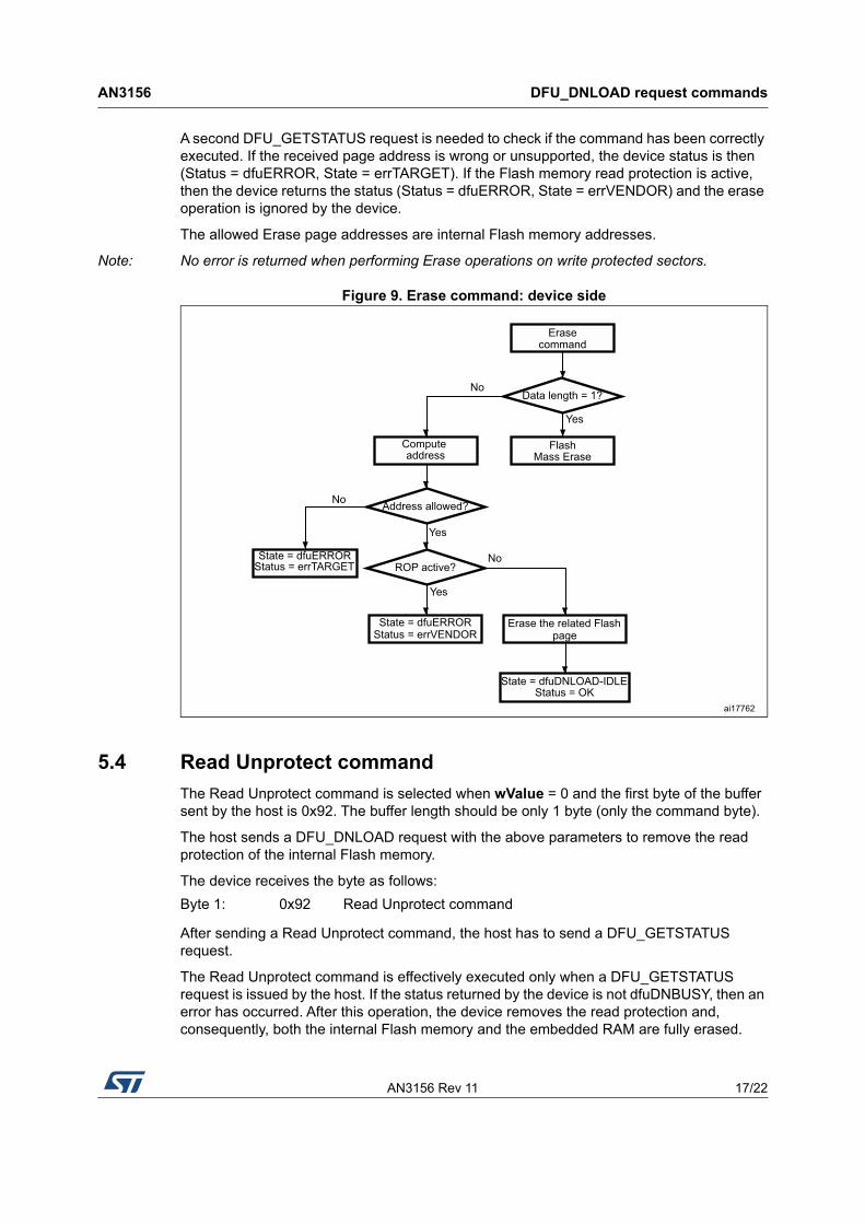
5.4 Read Unprotect command
The Read Unprotect command is selected when wValue = 0 and the first byte of the buffer sent by the host is 0x92. The buffer length should be only 1 byte (only the command byte).
The host sends a DFU_DNLOAD request with the above parameters to remove the read protection of the internal Flash memory.
The device receives the byte as follows:
After sending a Read Unprotect command, the host has to send a DFU_GETSTATUS request.
The Read Unprotect command is effectively executed only when a DFU_GETSTATUS request is issued by the host. If the status returned by the device is not dfuDNBUSY, then an error has occurred. After this operation, the device removes the read protection and, consequently, both the internal Flash memory and the embedded RAM are fully erased.
Erasecommand
Mass Erase
No
Yes
Data length = 1?
Flash
No
Yes
Erase the related Flashpage
Address allowed?
ROP active?
Yes
No
State = dfuERRORStatus = errVENDOR
Compute address
State = dfuERRORStatus = errTARGET
State = dfuDNLOAD-IDLEStatus = OK
ai17762
Byte 1: 0x92 Read Unprotect command
DFU_DNLOAD request commands AN3156
18/22 AN3156 Rev 11
Hence, just after executing this command, the device disconnects itself and executes a system reset. In this case, the device is unable to respond to a second Get Status request, and the host has to wait until the device is enumerated again.
A second DFU_GETSTATUS request may also be issued (if the device is still connected) to check if the command has been correctly executed. If the device fails to execute the command it returns an error status (depending on the error type).
Figure 10. Read Unprotect command: device side
5.5 Leave DFU mode
It is possible to exit DFU mode (and bootloader) and jump to a loaded application (in the internal Flash memory or in the embedded RAM) using the DFU download request.
The host sends a DFU_DNLOAD request with 0 data length (no data stage after the request) to inform the device that it will have to exit DFU mode. The device acknowledges this request if the current state is dfuDNLOAD-IDLE or dfuIDLE.
The DFU Leave operation is effectively executed only when a DFU_GETSTATUS request is issued by the host. If the status returned by the device is not dfuMANIFEST an error has occurred. After this operation, the device performs the following actions:
• disconnects itself
• initializes the registers of the peripherals used by the bootloader to their default reset values
• initializes the user application main stack pointer
• jumps to the memory location programmed in the received ‘address pointer + 4’, which corresponds to the address of the application’s reset handler. For example if the received address is 0x0800 0000, the bootloader will jump to the memory location programmed at address 0x0800 0004. In general, the host must send the base address where the application to jump to is programmed.
Read Unprotectcommand
System reset
Remove Read Protection
Disconnect USB device
Erase the embedded RAM
Operation done?
Yes
No
State = dfuERRORStatus = errUNKOWN
ai17763
AN3156 Rev 11 19/22
AN3156 DFU_DNLOAD request commands
21
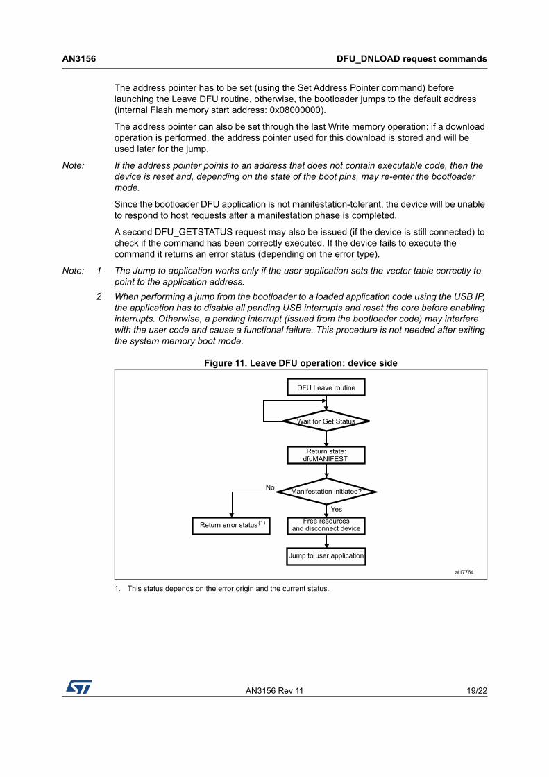
The address pointer has to be set (using the Set Address Pointer command) before launching the Leave DFU routine, otherwise, the bootloader jumps to the default address (internal Flash memory start address: 0x08000000).
The address pointer can also be set through the last Write memory operation: if a download operation is performed, the address pointer used for this download is stored and will be used later for the jump.
Note: If the address pointer points to an address that does not contain executable code, then the device is reset and, depending on the state of the boot pins, may re-enter the bootloader mode.
Since the bootloader DFU application is not manifestation-tolerant, the device will be unable to respond to host requests after a manifestation phase is completed.
A second DFU_GETSTATUS request may also be issued (if the device is still connected) to check if the command has been correctly executed. If the device fails to execute the command it returns an error status (depending on the error type).
Note: 1 The Jump to application works only if the user application sets the vector table correctly to point to the application address.
2 When performing a jump from the bootloader to a loaded application code using the USB IP, the application has to disable all pending USB interrupts and reset the core before enabling interrupts. Otherwise, a pending interrupt (issued from the bootloader code) may interfere with the user code and cause a functional failure. This procedure is not needed after exiting the system memory boot mode.
Figure 11. Leave DFU operation: device side
1. This status depends on the error origin and the current status.
DFU Leave routine
Wait for Get Status
Return state:dfuMANIFEST
Free resourcesand disconnect device
Manifestation initiated?
Jump to user application
Return error status(1)
Yes
No
ai17764
Bootloader protocol version evolution AN3156
20/22 AN3156 Rev 11
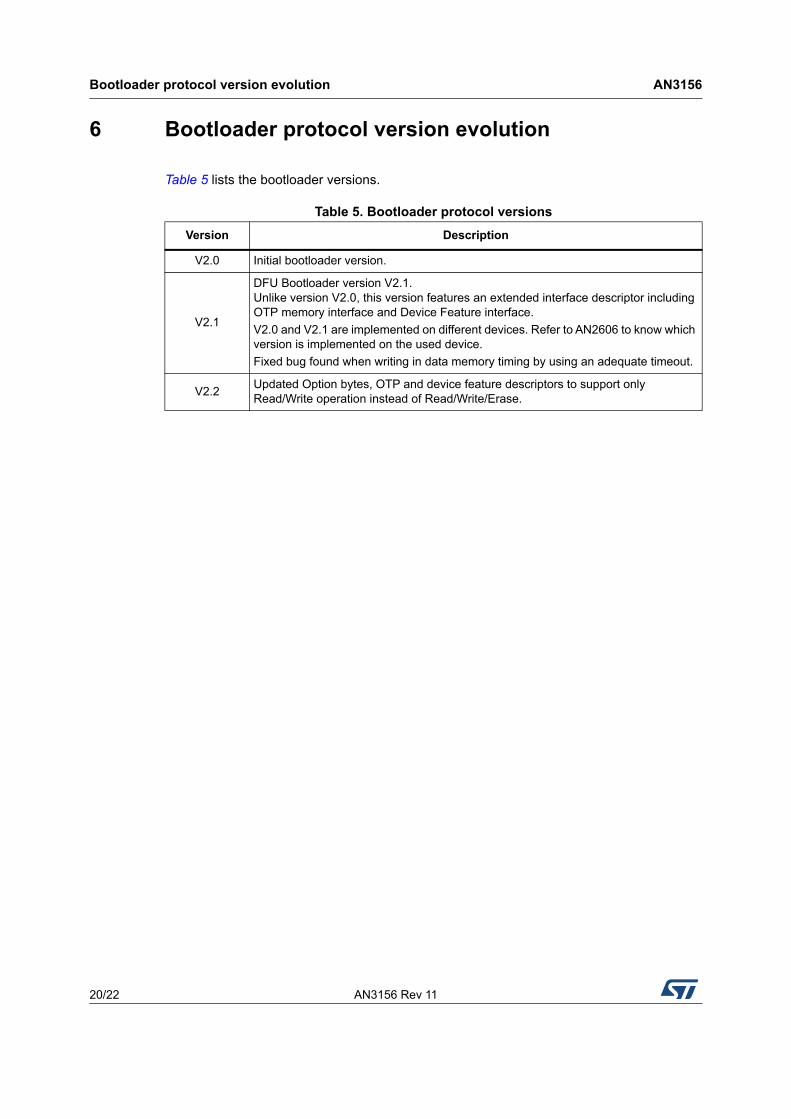
6 Bootloader protocol version evolution
Table 5 lists the bootloader versions.
Table 5. Bootloader protocol versions
Version Description
V2.0 Initial bootloader version.
V2.1
DFU Bootloader version V2.1. Unlike version V2.0, this version features an extended interface descriptor including OTP memory interface and Device Feature interface.
V2.0 and V2.1 are implemented on different devices. Refer to AN2606 to know which version is implemented on the used device.
Fixed bug found when writing in data memory timing by using an adequate timeout.
V2.2Updated Option bytes, OTP and device feature descriptors to support only Read/Write operation instead of Read/Write/Erase.
AN3156 Rev 11 21/22
AN3156 Revision history
21
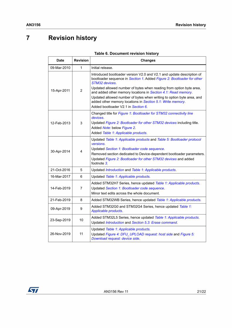
7 Revision history
Table 6. Document revision history
Date Revision Changes
09-Mar-2010 1 Initial release.
15-Apr-2011 2
Introduced bootloader version V2.0 and V2.1 and update description of bootloader sequence in Section 1. Added Figure 2: Bootloader for other STM32 devices.
Updated allowed number of bytes when reading from option byte area, and added other memory locations in Section 4.1: Read memory.
Updated allowed number of bytes when writing to option byte area, and added other memory locations in Section 5.1: Write memory.
Added bootloader V2.1 in Section 6.
12-Feb-2013 3
Changed title for Figure 1: Bootloader for STM32 connectivity line devices.
Updated Figure 2: Bootloader for other STM32 devices including title.
Updated Figure 4: DFU_UPLOAD request: host side and Figure 5: Download request: device side.
AN3156
22/22 AN3156 Rev 11
IMPORTANT NOTICE – PLEASE READ CAREFULLY
STMicroelectronics NV and its subsidiaries (“ST”) reserve the right to make changes, corrections, enhancements, modifications, and improvements to ST products and/or to this document at any time without notice. Purchasers should obtain the latest relevant information on ST products before placing orders. ST products are sold pursuant to ST’s terms and conditions of sale in place at the time of order acknowledgement.
Purchasers are solely responsible for the choice, selection, and use of ST products and ST assumes no liability for application assistance or the design of Purchasers’ products.
No license, express or implied, to any intellectual property right is granted by ST herein.
Resale of ST products with provisions different from the information set forth herein shall void any warranty granted by ST for such product.
ST and the ST logo are trademarks of ST. For additional information about ST trademarks, please refer to www.st.com/trademarks. All other product or service names are the property of their respective owners.
Information in this document supersedes and replaces information previously supplied in any prior versions of this document.