September 2011 Doc ID 022240 Rev 1 1/46 AN3984 Application note IIR filter design equations for Sound Terminal ® devices Introduction The purpose of this document is to provide a tool to calculate the IIR filter coefficients to program the Sound Terminal ® devices from STMicroelectronics. For each filter the procedure and the formulas to calculate the coefficient will be described; the Matlab code is given in Appendix A: Matlab code (functions) on page 24. A generalized set of equations can be formulated for the design of first-order low-pass and high-pass filters and of second-order filters. A specialized set of equations is devised for designing parametric biquad EQ filters. As with any other filter design procedure, the desired characteristics of the filter are to be made available. The parameters governing the characteristics of each filter are: ■ fc: filter cutoff frequency which is the -3dB corner frequency or the midpoint frequency in a peak or notch filter ■ fs: sampling frequency ■ Q: quality factor (not applicable for low and high-shelf filters) ■ Slope: applicable only for low and high-shelf filters ■ Gain: the boost or the attenuation at f = fc These parameters can be used to determine the coefficients of the digital filter transfer function. www.st.com
Transcript
September 2011 Doc ID 022240 Rev 1 1/46
AN3984Application note
IIR filter design equations for Sound Terminal® devices
IntroductionThe purpose of this document is to provide a tool to calculate the IIR filter coefficients to program the Sound Terminal® devices from STMicroelectronics.
For each filter the procedure and the formulas to calculate the coefficient will be described; the Matlab code is given in Appendix A: Matlab code (functions) on page 24.
A generalized set of equations can be formulated for the design of first-order low-pass and high-pass filters and of second-order filters.
A specialized set of equations is devised for designing parametric biquad EQ filters. As with any other filter design procedure, the desired characteristics of the filter are to be made available.
The parameters governing the characteristics of each filter are:
■ fc: filter cutoff frequency which is the -3dB corner frequency or the midpoint frequency in a peak or notch filter
■ fs: sampling frequency
■ Q: quality factor (not applicable for low and high-shelf filters)
■ Slope: applicable only for low and high-shelf filters
■ Gain: the boost or the attenuation at f = fc
These parameters can be used to determine the coefficients of the digital filter transfer function.
2.1 DefinitionA filter is said to be stable in the z-domain if the roots (or poles) of the filter lie inside the unit circle.
This definition of stability can be translated in terms of the filter coefficients.
2.2 First-order filterFor a first-order filter, the stability condition that needs to be satisfied is that the pole of the filter lies within the unit circle.
In terms of the coefficients, the condition can be given as:
Equation 5
2.3 Second-order filterFor a 2nd-order filter, two conditions must be satisfied to ensure filter stability and translated in terms of the filter coefficients they are:
Equation 6
11 <a
)1(
1
21
2
aa
a
+<
<
AN3984 First-order filter design (LPF and HPF)
Doc ID 022240 Rev 1 7/46
3 First-order filter design (LPF and HPF)
The preliminary step to obtain the coefficients for the first-order low-pass filter or high-pass filter is to define three constants obtained from the filter parameters:
Equation 7
In a first-order filter both the coefficients a2 and b2 are null.
The denominator coefficients are identical for both an LPF and an HPF designed for the same cutoff frequency and they are computed as follows:
Equation 8
The numerator for an LPF can be calculated as follows:
Equation 9
The numerator for an HPF can be calculated as follows:
Equation 10
The coefficient used in APWorkbench can be calculated by applying these formulas:
Equation 11
( )K
Kff
c
scc
+==
⋅⋅=
12tan
2
αωπω
( )α
Ka
a−
−=
=1
1
1
0
α
αKb
Kb
=
=
1
0
α
α1
1
1
0
−=
=
b
b
( )
( )
( )
( )0
00
0
22
0
11
0
22
0
11
22
22
22
abbt Coefficien
aat aCoefficien
aaat Coefficien
abt bCoefficien
abbt Coefficien
=
−=
−=
=
=
Second-order filter design AN3984
8/46 Doc ID 022240 Rev 1
4 Second-order filter design
4.1 Low-pass and high-pass filtersThe preliminary step to obtain the coefficients for a second-order filter is the calculation of these coefficients obtained from the filter parameters:
Equation 12
The denominator coefficients are the same for both an LPF and an HPF if designed for the same cutoff frequency. They are computed as follows:
Equation 13
4.1.1 Low-pass filter
The numerator coefficient for a second-order LPF can be calculated as follows:
Equation 14
( )
WQKDE
KKW
Kff
c
s
cc
++=
+==
=
⋅⋅=
1
1
2tan
2
2
α
ω
πϑ
( )
DE
WQK
a
DEWa
a
+−=
−⋅=
=
1
12
1
2
1
0
DEW
b
DEW
b
DEW
b
=
⋅=
=
2
1
0
2
AN3984 Second-order filter design
Doc ID 022240 Rev 1 9/46
For a second-order LPF, the coefficients given in APWorkbench can be calculated as follows:
Equation 15
4.1.2 High-pass filter
The numerator coefficient for a second-order HPF can be calculated as follows:
Equation 16
For a second-order HPF, the coefficients given in APWorkbench can be calculated as follows:
Equation 17
DEWbt Coefficien
DE
WQK
t aCoefficien
DEWat Coefficien
DEWt bCoefficien
DEWbt Coefficien
⋅=
+−−=
−⋅−=
=
=
21
2
1
112
2
0
2
1
2
1
DEb
DEW
b
DEb
1
2
1
2
1
0
=
⋅−=
=
DEbt Coefficien
DE
WQK
t aCoefficien
DEWat Coefficien
DEt bCoefficien
DEbt Coefficien
121
2
1
112
1
12
0
2
1
2
1
⋅=
+−−=
−⋅−=
=
−=
Second-order filter design AN3984
10/46 Doc ID 022240 Rev 1
4.2 Peak filtersThe first step is the calculation of the constant gain obtained from the gain filter parameter (GdB is expressed in dB).
Equation 18
The filter coefficients are different if the gain is positive or negative.
4.2.1 Peak filter - negative gain (cut)
The cut value is calculated with the following equation:
Equation 19
The filter coefficient can be calculated as follows:
Equation 20
)115129254.0exp( ⋅= dBGainGain
WGain
QKCutValue +⎟⎠⎞⎜
⎝⎛⋅+= 1
( )
( )
CutValue
WQK
b
CutValueW
b
CutValue
WQK
b
CutValue
WGain
Q
a
CutValueW
a
a
)1(
12
1
1
14
1
2
1
0
2
1
0
+−=
−⋅=
⎟⎟⎠
⎞⎜⎜⎝
⎛++
=
⎟⎟⎟⎟
⎠
⎞
⎜⎜⎜⎜
⎝
⎛ +−=
−⋅=
=
AN3984 Second-order filter design
Doc ID 022240 Rev 1 11/46
The coefficients in the APWorkbench are consequently calculated as follows:
Equation 21
4.2.2 Peak filter - positive gain (boost)
The boost value is calculated with the following equation:
Equation 22
The filter coefficient can be calculated as follows:
Equation 23
CutValue
WQK
bt Coefficien
CutValue
WKGain
Q
t aCoefficien
CutValueWat Coefficien
CutValue
WQK
t bCoefficien
CutValueWbt Coefficien
++⋅=
+⋅−−=
−=
+−=
−=
1
21
2
1
12
)1(
12
0
2
1
2
1
WQKBoostValue ++= 1
BoostValue
WQ
GainKb
BoostValueW
b
BoostValue
WQ
GainKb
BoostValue
WQK
a
BoostValue
WQ
GainKa
a
)1(
12
)1(2
1
)1(
1
2
1
0
2
1
0
+⋅−=
−⋅=
+⋅+⋅=
⎟⎟⎠
⎞⎜⎜⎝
⎛+−
=
+⋅+=
=
Second-order filter design AN3984
12/46 Doc ID 022240 Rev 1
The coefficients in the APWorkbench are consequently calculated as follows:
Equation 24
4.3 Shelf filtersThe coefficient gain is defined in Equation 25.
Equation 25
The coefficients α and β are calculated as follows:
Equation 26
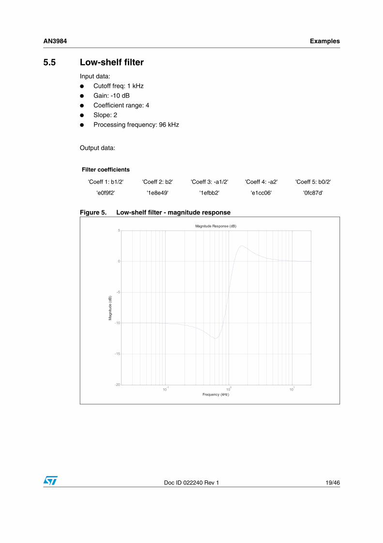
4.3.1 Low-shelf filter
The coefficients for an LSF can be calculated as follows:
Equation 27
The coefficient to load in APWorkbench can be calculated by applying the calculation already shown in Equation 11.
BoostValue
WKQ
Gainbt Coefficien
BoostValue
WQK
t aCoefficien
BoostValueWat Coefficien
BoostValue
WKQ
Gain
t bCoefficien
BoostValueWbt Coefficien
+⋅+⋅=
+−−=
−=
+⋅−=
−=
1
21
2
1
12
)1(
12
0
2
1
2
1
)40(10dBGain
Gain =
( )
Gain
SGainGainc
⋅⋅=
⎟⎟⎠
⎞⎜⎜⎝
⎛+⎟
⎠⎞
⎜⎝⎛ −⋅⎟⎟
⎠
⎞⎜⎜⎝
⎛⎟⎠⎞
⎜⎝⎛+⋅=
αβ
ϑα
2
21112
sin
( ) ( )( ) ( )
( ) ( )( ) ( )( )
( ) ( )( )( ) ( )( )βϑ
ϑβϑ
βϑϑ
βϑ
−⋅−−+⋅=⋅+−−⋅⋅=
+⋅−−+⋅=−⋅−++=
⋅++−⋅−=+⋅−++=
c
c
c
c
c
c
GainGainGainbGainGainGainb
GainGainGainbGainGaina
GainGainaGainGaina
cos11cos112
cos11cos11
cos112cos11
2
1
0
2
1
0
AN3984 Second-order filter design
Doc ID 022240 Rev 1 13/46
4.3.2 High-shelf filter
The coefficients for an HSF can be calculated as follows:
Equation 28
The coefficient to load in APWorkbench to program a HSF can be computed by applying the formulas shown in Equation 11.
4.4 Notch filterThe first step is to define the constant α(a):
Equation 29
The coefficients for a notch filter can be calculated as follows:
Equation 30
The coefficients to load in APWorkbench can be calculated using Equation 11.
( ) ( )( ) ( )
( ) ( )( ) ( )( )
( ) ( )( )( ) ( )( )βϑ
ϑβϑ
βϑϑ
βϑ
−⋅−++⋅=⋅+−−⋅⋅−=
+⋅−++⋅=−⋅−−+=
⋅+−−⋅=+⋅−−+=
c
c
c
c
c
c
GainGainGainbGainGainGainb
GainGainGainbGainGaina
GainGainaGainGaina
cos11cos112
cos11cos11cos112
cos11
2
1
0
2
1
0
a. ϑc is defined in Equation 12
( )Q
c
⋅=2sin ϑ
α
1cos2
11
cos21
2
1
0
2
1
0
=⋅−=
=−=
⋅−=+=
bbbaaa
c
ϑ
αϑ
α
Second-order filter design AN3984
14/46 Doc ID 022240 Rev 1
4.5 All-pass filterEquation 29 allows calculating the constant α.
The coefficients for an APF can be calculated as follows:
Equation 31
The coefficients to load in APWorkbench can be calculated using Equation 11.
4.6 Band-pass filterEquation 29 allows calculating the constant α while Equation 32 is used to calculate the normalized gain.
Equation 32
The coefficients for a BPF can be calculated as follows(b):
Equation 33
The coefficients to load in APWorkbench can be calculated using Equation 11.
αϑ
αα
ϑα
+==⋅−=
−=−=
⋅−=+=
1cos2
11
cos21
2
11
0
2
1
0
bab
baaa
c
c
b. α is defined in Equation 29, ϑc is defined in Equation 12.
The abbreviations and acronyms used throughout this application note are defined as follows:
● fc: cutoff frequency
● fs: sampling frequency
● Q: filter quality factor
● G: gain
● LPF: low-pass filter
● HPF: high-pass filter
● LSF: low-shelf filter
● HSF: high-shelf filter
● APF: all-pass filter
● BPF: band-pass filter
AN3984 Revision history
Doc ID 022240 Rev 1 45/46
6 Revision history
Table 1. Document revision history
Date Revision Changes
26-Sep-2011 1 Initial release.
AN3984
46/46 Doc ID 022240 Rev 1
Please Read Carefully:
Information in this document is provided solely in connection with ST products. STMicroelectronics NV and its subsidiaries (“ST”) reserve theright to make changes, corrections, modifications or improvements, to this document, and the products and services described herein at anytime, without notice.
All ST products are sold pursuant to ST’s terms and conditions of sale.
Purchasers are solely responsible for the choice, selection and use of the ST products and services described herein, and ST assumes noliability whatsoever relating to the choice, selection or use of the ST products and services described herein.
No license, express or implied, by estoppel or otherwise, to any intellectual property rights is granted under this document. If any part of thisdocument refers to any third party products or services it shall not be deemed a license grant by ST for the use of such third party productsor services, or any intellectual property contained therein or considered as a warranty covering the use in any manner whatsoever of suchthird party products or services or any intellectual property contained therein.
UNLESS OTHERWISE SET FORTH IN ST’S TERMS AND CONDITIONS OF SALE ST DISCLAIMS ANY EXPRESS OR IMPLIEDWARRANTY WITH RESPECT TO THE USE AND/OR SALE OF ST PRODUCTS INCLUDING WITHOUT LIMITATION IMPLIEDWARRANTIES OF MERCHANTABILITY, FITNESS FOR A PARTICULAR PURPOSE (AND THEIR EQUIVALENTS UNDER THE LAWSOF ANY JURISDICTION), OR INFRINGEMENT OF ANY PATENT, COPYRIGHT OR OTHER INTELLECTUAL PROPERTY RIGHT.
UNLESS EXPRESSLY APPROVED IN WRITING BY TWO AUTHORIZED ST REPRESENTATIVES, ST PRODUCTS ARE NOTRECOMMENDED, AUTHORIZED OR WARRANTED FOR USE IN MILITARY, AIR CRAFT, SPACE, LIFE SAVING, OR LIFE SUSTAININGAPPLICATIONS, NOR IN PRODUCTS OR SYSTEMS WHERE FAILURE OR MALFUNCTION MAY RESULT IN PERSONAL INJURY,DEATH, OR SEVERE PROPERTY OR ENVIRONMENTAL DAMAGE. ST PRODUCTS WHICH ARE NOT SPECIFIED AS "AUTOMOTIVEGRADE" MAY ONLY BE USED IN AUTOMOTIVE APPLICATIONS AT USER’S OWN RISK.
Resale of ST products with provisions different from the statements and/or technical features set forth in this document shall immediately voidany warranty granted by ST for the ST product or service described herein and shall not create or extend in any manner whatsoever, anyliability of ST.
ST and the ST logo are trademarks or registered trademarks of ST in various countries.
Information in this document supersedes and replaces all information previously supplied.
The ST logo is a registered trademark of STMicroelectronics. All other names are the property of their respective owners.
Australia - Belgium - Brazil - Canada - China - Czech Republic - Finland - France - Germany - Hong Kong - India - Israel - Italy - Japan - Malaysia - Malta - Morocco - Philippines - Singapore - Spain - Sweden - Switzerland - United Kingdom - United States of America