February 2017 DocID028192 Rev 2 1/27 1 AN4749 Application note Managing low-power consumption on STM32F7 Series microcontrollers Introduction The STM32F7 Series microcontrollers embed a smart architecture taking advantage of the ST’s ART- accelerator ™ as well as the L1-cache to deliver the maximum performance (5 CoreMark/ MHz) and provide the best energy efficiency no matter whether the code is executed from an embedded Flash memory or external memories. This application note is splitted into 2 parts: • The first part describes the low-power modes featured in the STM32F7 Series devices and how to take advantage from the smart architecture to get the best trade-off between the performance and the power consumption. • The second part describes a real application case that highlights the power efficiency on the STM32F7 Series. This application note is provided with X-CUBE-LPDEMO-F7 embedded software package that contains one project with 2 different workspaces: • Flash_AXI: the code is executed from the Flash memory on the AXIM interface at the address 0x0800 0000. • Flash_ITCM: the code is executed from the Flash memory on the ITCM interface at the address 0x0020 0000. All read write data (RW) are located at DTCM-RAM and SRAM1. For more details about the embedded software, refer to the readme file inside the embedded software package. www.st.com
Transcript
February 2017 DocID028192 Rev 2 1/27
1
AN4749Application note
Managing low-power consumption on STM32F7 Series microcontrollers
Introduction
The STM32F7 Series microcontrollers embed a smart architecture taking advantage of the ST’s ART- accelerator™ as well as the L1-cache to deliver the maximum performance (5 CoreMark/ MHz) and provide the best energy efficiency no matter whether the code is executed from an embedded Flash memory or external memories.
This application note is splitted into 2 parts:
• The first part describes the low-power modes featured in the STM32F7 Series devices and how to take advantage from the smart architecture to get the best trade-off between the performance and the power consumption.
• The second part describes a real application case that highlights the power efficiency on the STM32F7 Series.
This application note is provided with X-CUBE-LPDEMO-F7 embedded software package that contains one project with 2 different workspaces:
• Flash_AXI: the code is executed from the Flash memory on the AXIM interface at the address 0x0800 0000.
• Flash_ITCM: the code is executed from the Flash memory on the ITCM interface at the address 0x0020 0000.
All read write data (RW) are located at DTCM-RAM and SRAM1.
For more details about the embedded software, refer to the readme file inside the embedded software package.
AN4749 STM32F7 Series power consumption and performance
26
1 STM32F7 Series power consumption and performance
The embedded system designers are currently facing the need to make a trade-off between the power efficiency and a high performance, especially with the recent high-performance microcontrollers such as the STM32F7 Series. The low-power modes are implemented with other features to reduce the average current consumption over the life of an application.
This part aims to describe the STM32F7 low-power modes and highlights the features that contribute in power consumption reduction.
1.1 Low-power modes
This part gives an overview of the STM32F7 Series power mode consumption.
1.1.1 Static modes overview
By default, and after power-on or a system reset, the STM32F7 Series devices are in Run mode, which is a fully active mode. The low-power modes are available to save power when the CPU does not need to be kept running.
It is up to the user to switch between the power modes during the application processing in order to reduce the overall average consumption by keeping the devices as much as possible in low-power modes as described in Figure 1. The user has just to select each time the low-power mode with the features that fit his design requirements.
Figure 1. Power mode switch
STM32F7 Series power consumption and performance AN4749
6/27 DocID028192 Rev 2
The STM32F7 Series devices feature four main low-power modes:
• Sleep mode
– Only the CPU clock is stopped.
The cortex-M7 clock is stopped and the peripherals are kept running. The current consumption increases with the clock frequency. As in Run mode, the user should be aware of system configuration rules that concern the system clock and voltage regulator scales.
• Stop mode:
– Lowest power consumption while all the SRAM and registers are kept.
– The Cortex-M7 core is stopped. PLL, HSI, HSE are disabled.
– All I/O pins keep the same state as the Run mode.
– All clocks in 1.2V domain are switched-off.
– The main regulator and low-power regulator can be in normal mode or in under-drive mode.
– The Flash memory is working in Stop mode or Deep-power down mode to save more static power.
• Standby mode:
– This mode has the lowest current consumption.
– The Cortex-M7 core is stopped and the clocks are switched off.
– The 1.2 domain is powered off (regulator is disabled).
– The SRAM and registers contents are lost except for the registers in the backup domain (RTC registers, RTC backup register and backup SRAM) and standby circuitry.
– All I/O pins are high impedance except for:
- Reset pad
- PC13 if configured for tamper, time stamp, RTC Alarm out, or RTC clock calibration out
- WKUP pins (PA0/PA2/PC1/PC13/PI8/PI11), if enabled
• VBAT mode:
– This mode is used only when the main digital supply (VDD) is turned off.
– The circuit is supplied through VBAT pin which should be connected to an external supply voltage (a battery or any other source).
– The VBAT pin powers the backup domain (RTC registers, RTC backup register and backup SRAM).
DocID028192 Rev 2 7/27
AN4749 STM32F7 Series power consumption and performance
26
1.1.2 Dynamic modes overview
• STM32F7 system architecture
The STM32F7 Series devices embed a new architecture, taking advantage of the ST’s ART- accelerator™ as well as the L1-cache to deliver the maximum performance (5 CoreMark/MHz) and to reduce the power consumption.
Figure 2 shows the overall system architecture of STM32F7 Series devices as well as the bus matrix connections.
Figure 2. System architecture for STM32F7 Series devices
1. I/D cache size:- For STM32F74xxx and STM32F75xxx devices: 4 Kbytes.
- For STM32F72xxx and STM32F73xxx devices: 8 Kbytes.
- For STM32F76xxx and STM32F77xxx devices: 16 Kbytes.
STM32F7 Series power consumption and performance AN4749
8/27 DocID028192 Rev 2
1.2 Power consumption and performance enhancement
1.2.1 Tips for saving power consumption
In all the STM32 families many power saving features can help to reduce the current consumption and reach an optimal trade-off between the performance processing and the power efficiency.
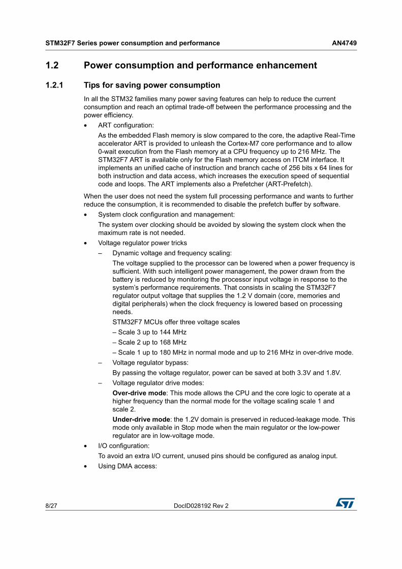
• ART configuration:
As the embedded Flash memory is slow compared to the core, the adaptive Real-Time accelerator ART is provided to unleash the Cortex-M7 core performance and to allow 0-wait execution from the Flash memory at a CPU frequency up to 216 MHz. The STM32F7 ART is available only for the Flash memory access on ITCM interface. It implements an unified cache of instruction and branch cache of 256 bits x 64 lines for both instruction and data access, which increases the execution speed of sequential code and loops. The ART implements also a Prefetcher (ART-Prefetch).
When the user does not need the system full processing performance and wants to further reduce the consumption, it is recommended to disable the prefetch buffer by software.
• System clock configuration and management:
The system over clocking should be avoided by slowing the system clock when the maximum rate is not needed.
• Voltage regulator power tricks
– Dynamic voltage and frequency scaling:
The voltage supplied to the processor can be lowered when a power frequency is sufficient. With such intelligent power management, the power drawn from the battery is reduced by monitoring the processor input voltage in response to the system’s performance requirements. That consists in scaling the STM32F7 regulator output voltage that supplies the 1.2 V domain (core, memories and digital peripherals) when the clock frequency is lowered based on processing needs.
STM32F7 MCUs offer three voltage scales
– Scale 3 up to 144 MHz
– Scale 2 up to 168 MHz
– Scale 1 up to 180 MHz in normal mode and up to 216 MHz in over-drive mode.
– Voltage regulator bypass:
By passing the voltage regulator, power can be saved at both 3.3V and 1.8V.
– Voltage regulator drive modes:
Over-drive mode: This mode allows the CPU and the core logic to operate at a higher frequency than the normal mode for the voltage scaling scale 1 and scale 2.
Under-drive mode: the 1.2V domain is preserved in reduced-leakage mode. This mode only available in Stop mode when the main regulator or the low-power regulator are in low-voltage mode.
• I/O configuration:
To avoid an extra I/O current, unused pins should be configured as analog input.
• Using DMA access:
DocID028192 Rev 2 9/27
AN4749 STM32F7 Series power consumption and performance
26
Not just useful to improve the performance but allows also the device to consume less average current over the life of the application.
• Power mode switching:
Reduces the overall average consumption by keeping the device as much as possible in low-power modes.
• Code optimization:
– Uses compiler optimization.
– Simplifies the program flow for common cases.
1.2.2 Power consumption and performance using CoreMark
The purpose of this analysis is to seek the best compromise between the power consumption and the performance.
This section shows the impact on the performance and the power consumption when executing the code from internal memories as ITCM-RAM, Flash ITCM and Flash AXI.
Thus 3 cases will be analyzed: the code running from ITCM-RAM, the code running from Flash ITCM with ART enabled and then disabled and the final case is executing the code from Flash AXI with cache enabled and then disabled. In all cases data are stored in DTCM-RAM.
In this analysis all data are extracted from STM32F7 datasheets. For more details about current consumption in Run mode, refer to STM32F7 datasheets available from ST web site: www.st.com/stm32.
Figure 3 shows the results of the power consumption using CoreMark.
Figure 3. Current consumption of STM32F7 Series devices for different memoryconfigurations (all peripheral disabled)
STM32F7 Series power consumption and performance AN4749
10/27 DocID028192 Rev 2
When running the code from ITCM RAM the current consumption is the lowest.
When running the code from the internal Flash memory, the ART accelerator and the L1-cache (which have the same power consumption in all the scales) tend to reduce the number of access to the memory, thus reducing the overall power consumption and allow to achieve 5 CoreMark/MHz whatever the system clock frequency.
Disabling ART or cache increases the power consumption and reduces the MCU performance.
These results show that executing the code from ITCM RAM, Flash ITCM and Flash AXI are among the best configurations when executing the code from the internal Flash memory in term of power consumption and performance.
For more details on the MCU power consumption refer to Supply current characteristics section of STM32F7 datasheets.
DocID028192 Rev 2 11/27
AN4749 STM32F7 Series low-power application case
26
2 STM32F7 Series low-power application case
2.1 Application overview
The purpose of the application is to demonstrate the high performance and low-power modes on the STM32F7 Series devices using external memories.
The application consists of a basic example of a smart watch, which displays the time on the STM32F746G Discovery display, gives the possibility to choose from where to load the screensaver through a menu and uses low-power modes to save energy consumption.
The power consumption measurements for different memory configurations are analyzed in Section 2.3.
2.1.1 Application functional description
Peripherals description
The main peripherals used by this application are:
• Clocks: two clocks are used
– HSE: 25 MHz system clock source
– LSE: 32.768 kHz low-speed external crystal to drive the RTC clock.
• GPIOs:
– PI11: used as user button to wake up the CPU from Stop and Standby mode.
– PJ12: input interrupt pin used to wake up the CPU from Stop mode for synchronizing time with PC
• LTDC: used to display the time and screensaver.
• Quad-SPI interface: used to load a picture from the Quad-SPI Nor Flash memory. It is configured in Memory Mapped mode so the external Flash memory is seen as an internal memory.
• SDRAM controller: used to store and load a picture into/from SDRAM device.
• RTC peripheral: provides a calendar with sub seconds, used to get the time and to wake up the CPU from Stop mode.
STM32F7 Series low-power application case AN4749
12/27 DocID028192 Rev 2
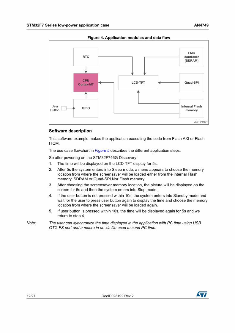
Figure 4. Application modules and data flow
Software description
This software example makes the application executing the code from Flash AXI or Flash ITCM.
The use case flowchart in Figure 5 describes the different application steps.
So after powering on the STM32F746G Discovery:
1. The time will be displayed on the LCD-TFT display for 5s.
2. After 5s the system enters into Sleep mode, a menu appears to choose the memory location from where the screensaver will be loaded either from the internal Flash memory, SDRAM or Quad-SPI Nor Flash memory.
3. After choosing the screensaver memory location, the picture will be displayed on the screen for 5s and then the system enters into Stop mode.
4. If the user button is not pressed within 10s, the system enters into Standby mode and wait for the user to press user button again to display the time and choose the memory location from where the screensaver will be loaded again.
5. If user button is pressed within 10s, the time will be displayed again for 5s and we return to step 4.
Note: The user can synchronize the time displayed in the application with PC time using USB OTG FS port and a macro in an xls file used to send PC time.
DocID028192 Rev 2 13/27
AN4749 STM32F7 Series low-power application case
26
Figure 5. Application flowchart
STM32F7 Series low-power application case AN4749
14/27 DocID028192 Rev 2
Figure 6 describes the low-power transition states of the application.
Figure 6. Application low-power transition states
DocID028192 Rev 2 15/27
AN4749 STM32F7 Series low-power application case
26
• Run_1 and Sleep:
This state is a combination of Run and Sleep modes. The system is in Run mode then enters into Sleep mode periodically after 1 s. The RTC wakes up the system from Sleep mode after 1 s to enter into Run mode again. During this state time will displayed on the LCD for 5 s
• Run_2 and Sleep:
The system enters into Run mode to display the menu then enters into Sleep mode immediately waiting for an LCD touch interrupt.
• Run_3 and Sleep:
The system enters into Run mode to display the screensaver and enters into sleep mode immediately, waiting for the RTC wakeup after 5 s.
• Stop:
The system enters into Stop mode after an RTC wakeup from Sleep mode. The exit of this mode can be done either by user button or by an RTC wakeup after 10 s.
• Standby :
The CPU enters into Standby mode after exit from Stop by an RTC wakeup and waits for the user button to be pressed to start the application again.
STM32F7 Series low-power application case AN4749
16/27 DocID028192 Rev 2
2.1.2 Embedded software architecture description
This application uses the STM32 cube firmware at HAL level and STemWin as graphical stack at middleware level. STemWin Library is a professional graphical stack library based on the Emwin solution from ST’s partner SEGGER. It enables the building up of Graphical User interfaces (GUIs) with any STM32, any LCD/TFT display and any LCD/TFT controller, taking advantage of STM32 hardware accelerations whenever possible.
For more details on STemWin library, refer to Getting started with STemWin library (AN4323) available on www.st.com.
Figure 7 illustrates the application embedded software component.
Figure 7. Application embedded software component
To demonstrate the high performance and power efficiency using external memories in STM32F7, the screensaver will be located into 3 different regions: the internal Flash memory, the external Quad-SPI nor Flash memory at the address 0x90000000 and SDRAM at the address 0xC0000000.
After linking the application, the screensaver will be stored in 2 regions: the internal Flash memory and Quad-SPI. A copy of the screensaver will be made through the CPU in SDRAM after running the application.
This application contains the following main source files:
• main.c: contains the overall needed functions for the application.
• stm32f7xx_it.c: contains the interrupt handlers for the application.
• system_stm32f7xx.c: contains the system clock configuration for the STM32F7 Series devices used in the application.
• stm32f7_Ip_modes.c: contains the different low-power mode functions used in the application.
DocID028192 Rev 2 17/27
AN4749 STM32F7 Series low-power application case
26
2.2 How to use the application
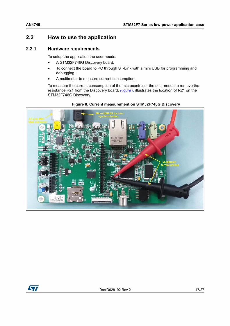
2.2.1 Hardware requirements
To setup the application the user needs:
• A STM32F746G Discovery board.
• To connect the board to PC through ST-Link with a mini USB for programming and debugging.
• A multimeter to measure current consumption.
To measure the current consumption of the microcontroller the user needs to remove the resistance R21 from the Discovery board. Figure 8 illustrates the location of R21 on the STM32F746G Discovery.
Figure 8. Current measurement on STM32F746G Discovery
STM32F7 Series low-power application case AN4749
18/27 DocID028192 Rev 2
2.2.2 Software requirements
This example is provided with 2 workspaces:
• Flash AXI: the code is executed from the Flash memory on the AXIM interface at the address 0x0800 0000.
• Flash ITCM: the code is executed from the Flash memory on the ITCM interface at the address 0x0020 0000.
So the user needs to choose the dedicated workspace to execute the code either from Flash AXI or Flash ITCM.
Figure 9. Application workspace selection
DocID028192 Rev 2 19/27
AN4749 STM32F7 Series low-power application case
26
2.2.3 Running application steps
This section describes our running application on the STM32F7 discovery board step by step:
1. First the time is displayed on the LCD-TFT for 5 s (Run 1 state).
Figure 10. LCD-TFT display
2. After 5 s, a menu appears with different icons to choose the load region of the screensaver.
Figure 11. Picture location selection
STM32F7 Series low-power application case AN4749
20/27 DocID028192 Rev 2
3. The picture is displayed for 5s.
Figure 12. STM32F7 low-power display
4. The system enters into Stop mode. If user button is not pressed within 10s, the system wakes up from Stop mode with RTC and enters into Standby mode.
Figure 13. Standby mode
5. If user button is pressed before 10s, the time and screensaver will be displayed successively and then the system enters to Stop mode again.
DocID028192 Rev 2 21/27
AN4749 STM32F7 Series low-power application case
26
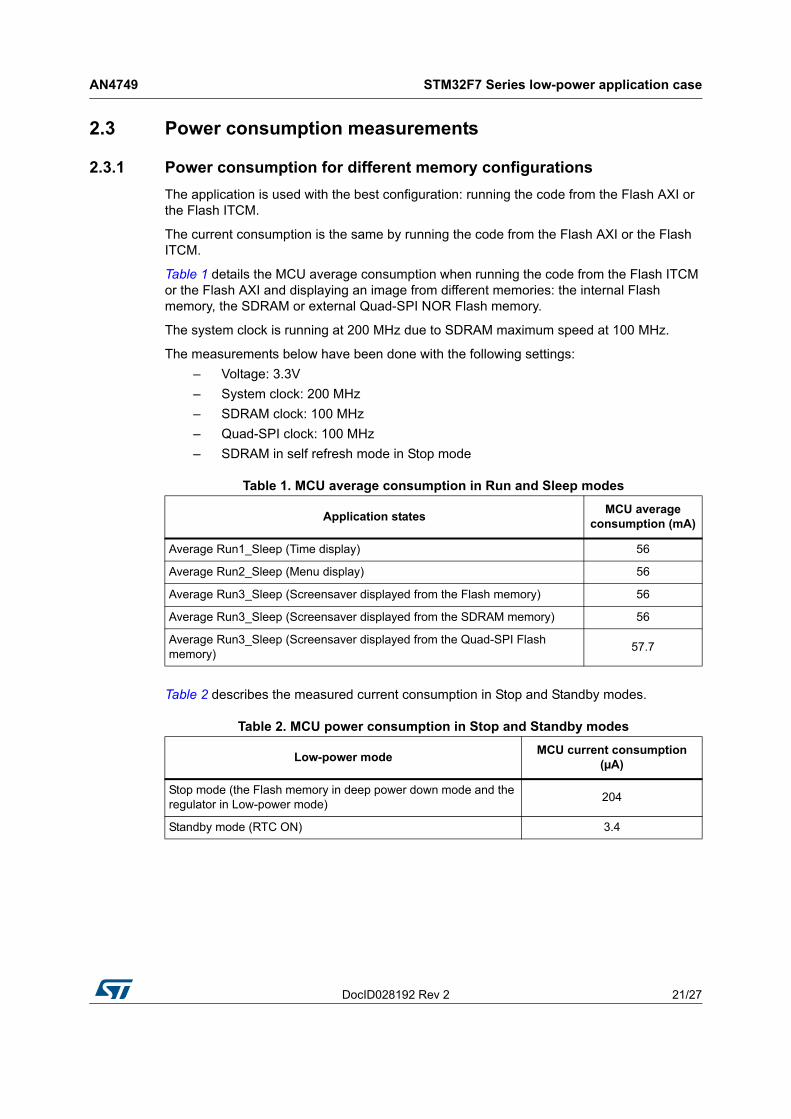
2.3 Power consumption measurements
2.3.1 Power consumption for different memory configurations
The application is used with the best configuration: running the code from the Flash AXI or the Flash ITCM.
The current consumption is the same by running the code from the Flash AXI or the Flash ITCM.
Table 1 details the MCU average consumption when running the code from the Flash ITCM or the Flash AXI and displaying an image from different memories: the internal Flash memory, the SDRAM or external Quad-SPI NOR Flash memory.
The system clock is running at 200 MHz due to SDRAM maximum speed at 100 MHz.
The measurements below have been done with the following settings:
– Voltage: 3.3V
– System clock: 200 MHz
– SDRAM clock: 100 MHz
– Quad-SPI clock: 100 MHz
– SDRAM in self refresh mode in Stop mode
Table 2 describes the measured current consumption in Stop and Standby modes.
Table 1. MCU average consumption in Run and Sleep modes
Application statesMCU average
consumption (mA)
Average Run1_Sleep (Time display) 56
Average Run2_Sleep (Menu display) 56
Average Run3_Sleep (Screensaver displayed from the Flash memory) 56
Average Run3_Sleep (Screensaver displayed from the SDRAM memory) 56
Average Run3_Sleep (Screensaver displayed from the Quad-SPI Flash memory)
57.7
Table 2. MCU power consumption in Stop and Standby modes
Low-power modeMCU current consumption
(µA)
Stop mode (the Flash memory in deep power down mode and the regulator in Low-power mode)
204
Standby mode (RTC ON) 3.4
STM32F7 Series low-power application case AN4749
22/27 DocID028192 Rev 2
2.3.2 Application energy balance
In this section, the cases described are showing the considerable power reduction using the STM32F7 low-power modes:
• Case 1: application based on Run mode
• Case 2: application based on Run and Sleep modes
• Case 3: application based on Run Sleep and Stop modes
• Case 4: application based on Run, Sleep, Stop and Standby modes
Case 1: application based on Run mode
Figure 14. Application based on Run mode
Case 2: application based on Run and Sleep modes
Figure 15. Application based on Run and Sleep modes
DocID028192 Rev 2 23/27
AN4749 STM32F7 Series low-power application case
26
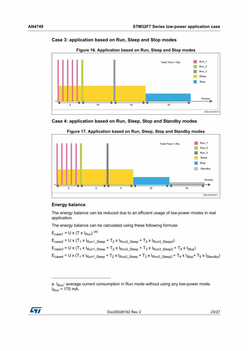
Case 3: application based on Run, Sleep and Stop modes
Figure 16. Application based on Run, Sleep and Stop modes
Case 4: application based on Run, Sleep, Stop and Standby modes
Figure 17. Application based on Run, Sleep, Stop and Standby modes
Energy balance
The energy balance can be reduced due to an efficient usage of low-power modes in real application.
The energy balance can be calculated using these following formula:
Ecase1 = U x (T x IRun) (a)
Ecase2 = U x (T1 x IRun1_Sleep + T2 x IRun2_Sleep + T3 x IRun3_Sleep2)
Ecase3 = U x (T1 x IRun1_Sleep + T2 x IRun2_Sleep + T3 x IRun3_Sleep2 + T4 x IStop)
Ecase4 = U x (T1 x IRun1_Sleep + T2 x IRun2_Sleep + T3 x IRun3_Sleep2 + T4 x IStop+ T5 x IStandby)
a. IRun: average current consumption in Run mode without using any low-power mode. IRun = 170 mA.
STM32F7 Series low-power application case AN4749
24/27 DocID028192 Rev 2
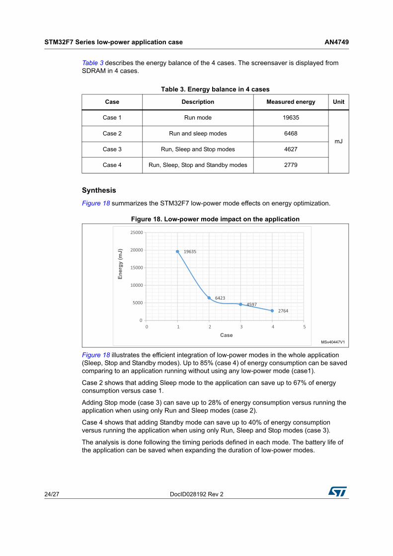
Table 3 describes the energy balance of the 4 cases. The screensaver is displayed from SDRAM in 4 cases.
Synthesis
Figure 18 summarizes the STM32F7 low-power mode effects on energy optimization.
Figure 18. Low-power mode impact on the application
Figure 18 illustrates the efficient integration of low-power modes in the whole application (Sleep, Stop and Standby modes). Up to 85% (case 4) of energy consumption can be saved comparing to an application running without using any low-power mode (case1).
Case 2 shows that adding Sleep mode to the application can save up to 67% of energy consumption versus case 1.
Adding Stop mode (case 3) can save up to 28% of energy consumption versus running the application when using only Run and Sleep modes (case 2).
Case 4 shows that adding Standby mode can save up to 40% of energy consumption versus running the application when using only Run, Sleep and Stop modes (case 3).
The analysis is done following the timing periods defined in each mode. The battery life of the application can be saved when expanding the duration of low-power modes.
Table 3. Energy balance in 4 cases
Case Description Measured energy Unit
Case 1 Run mode 19635
mJCase 2 Run and sleep modes 6468
Case 3 Run, Sleep and Stop modes 4627
Case 4 Run, Sleep, Stop and Standby modes 2779
DocID028192 Rev 2 25/27
AN4749 Conclusion
26
3 Conclusion
This application note demonstrates the low-power modes and the high performance on the STM32F7 Series devices using internal or external memories.
The first part describes the low-power modes featured in the STM32F7 Series devices and presents some tips to save power consumption. An analysis has been made also to seek the best compromise between the power consumption and performance when executing the code from internal memories using CoreMark.
The second part describes a basic example of a smart watch that highlights the overall power consumption and the impact of an efficient usage of low-power modes in a real application.
Revision history AN4749
26/27 DocID028192 Rev 2
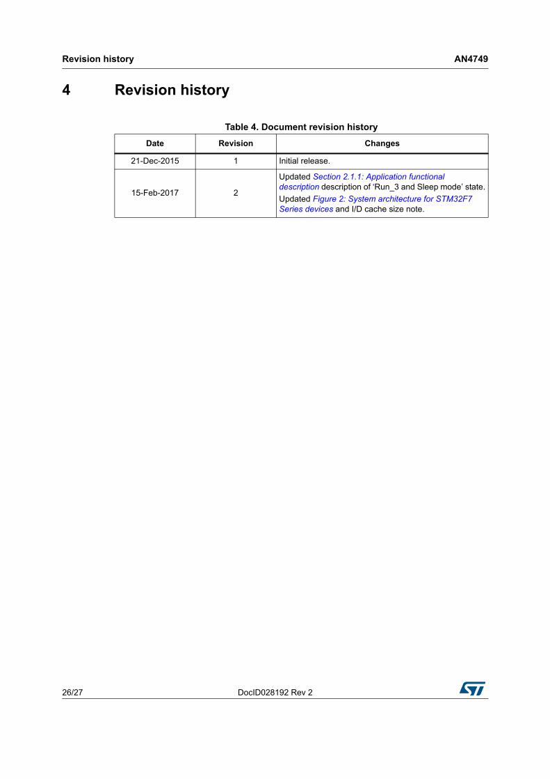
4 Revision history
Table 4. Document revision history
Date Revision Changes
21-Dec-2015 1 Initial release.
15-Feb-2017 2
Updated Section 2.1.1: Application functional description description of ‘Run_3 and Sleep mode’ state.
Updated Figure 2: System architecture for STM32F7 Series devices and I/D cache size note.
DocID028192 Rev 2 27/27
AN4749
27
IMPORTANT NOTICE – PLEASE READ CAREFULLY
STMicroelectronics NV and its subsidiaries (“ST”) reserve the right to make changes, corrections, enhancements, modifications, and improvements to ST products and/or to this document at any time without notice. Purchasers should obtain the latest relevant information on ST products before placing orders. ST products are sold pursuant to ST’s terms and conditions of sale in place at the time of order acknowledgement.
Purchasers are solely responsible for the choice, selection, and use of ST products and ST assumes no liability for application assistance or the design of Purchasers’ products.
No license, express or implied, to any intellectual property right is granted by ST herein.
Resale of ST products with provisions different from the information set forth herein shall void any warranty granted by ST for such product.
ST and the ST logo are trademarks of ST. All other product or service names are the property of their respective owners.
Information in this document supersedes and replaces information previously supplied in any prior versions of this document.