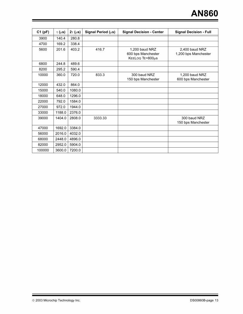
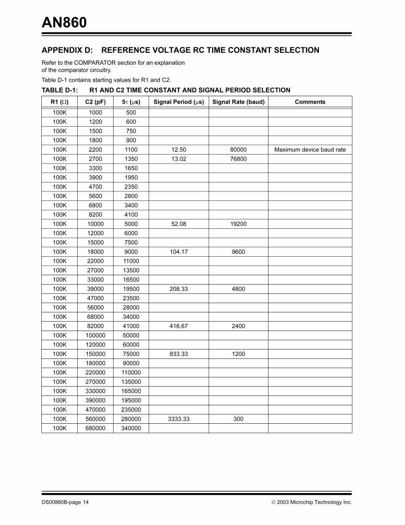
2003 Microchip Technology Inc. DS00860B-page 1 AN860 INTRODUCTION This application note describes a low cost, high performance UHF short-range radio ASK receiver design using the Microchip Technology rfRXD0420. The reference design is suitable for: • Wireless remote command and control • Remote Keyless Entry (RKE) • Security systems • Low power telemetry applications The specifics of this receiver reference design are: • Single channel, fixed frequency at 433.92 MHz • ASK modulation • Signal rate: 4800 baud Complete schematics and PCB layout are given in Appendix A. Bill of Materials (BOM) are in Appendix B. Gerber files are available in the companion file AN00860B.ZIP. ASK RECEIVER REFERENCE DESIGN Figure 1 is a block diagram of the receiver signal path with external components that apply to ASK operation of the rfRXD0420. In the sections that follow, the purpose of the RF stage, component selection, and performance trade-offs are discussed to assist the designer in understanding, optimizing and/or changing this receiver reference design to suit other applications. Crystal Oscillator and Crystal Selection The rfRXD0420 is a single-conversion superhetero- dyne architecture with a single IF frequency. The receive frequency is set by the crystal frequency (f XTAL ) and intermediate frequency (f if ). For this reference design, low-side injection of the Local Oscillator (f lo ) frequency was chosen. Calculation of the crystal, LO, and image frequencies are: Given: f rf = 433.92 MHz f if = 10.7 MHz PLL divide ratio = 16 (fixed) Crystal frequency (low-side injection): f XTAL-LOW = (f rf - f if ) / PLL divide ratio f XTAL-LOW = (433.92 MHz - 10.7 MHz) / 16 f XTAL-LOW = 26.45125 MHz Local oscillator frequency (low-side injection): f lo = f XTAL x PLL divide ratio f lo = 26.45125 MHz x 16 f lo = 423.22 MHz Image frequency (low-side injection): f rf-image = f rf - (2 x f if ) f rf-image = 433.92 MHz - (2 x 10.7 MHz) f rf-image = 412.52 MHz Frequency planning is illustrated in Figure 2. Author: Steven Bible Microchip Technology Inc. rfRXD0420 ASK Receiver Reference Design
Transcript
AN860
rfRXD0420 ASK Receiver Reference Design
INTRODUCTION
This application note describes a low cost, high
performance UHF short-range radio ASK receiver
design using the Microchip Technology rfRXD0420.
The reference design is suitable for:
• Wireless remote command and control
• Remote Keyless Entry (RKE)
• Security systems
• Low power telemetry applications
The specifics of this receiver reference design are:
• Single channel, fixed frequency at 433.92 MHz
• ASK modulation
• Signal rate: 4800 baud
Complete schematics and PCB layout are given in
Appendix A. Bill of Materials (BOM) are in Appendix B.
Gerber files are available in the companion file
AN00860B.ZIP.
ASK RECEIVER REFERENCE DESIGN
Figure 1 is a block diagram of the receiver signal path
with external components that apply to ASK operation
of the rfRXD0420. In the sections that follow, the
purpose of the RF stage, component selection, and
performance trade-offs are discussed to assist the
designer in understanding, optimizing and/or changing
this receiver reference design to suit other applications.
Crystal Oscillator and Crystal Selection
The rfRXD0420 is a single-conversion superhetero-
dyne architecture with a single IF frequency. The
receive frequency is set by the crystal frequency (fXTAL)
and intermediate frequency (fif).
For this reference design, low-side injection of the
Local Oscillator (flo) frequency was chosen. Calculation
of the crystal, LO, and image frequencies are:
Given:
frf = 433.92 MHz
fif = 10.7 MHz
PLL divide ratio = 16 (fixed)
Crystal frequency (low-side injection):
fXTAL-LOW = (frf - fif) / PLL divide ratio
fXTAL-LOW = (433.92 MHz - 10.7 MHz) / 16
fXTAL-LOW = 26.45125 MHz
Local oscillator frequency (low-side injection):
flo = fXTAL x PLL divide ratio
flo = 26.45125 MHz x 16
flo = 423.22 MHz
Image frequency (low-side injection):
frf-image = frf - (2 x fif)
frf-image = 433.92 MHz - (2 x 10.7 MHz)
frf-image = 412.52 MHz
Frequency planning is illustrated in Figure 2.
Author: Steven Bible
Microchip Technology Inc.
2003 Microchip Technology Inc. DS00860B-page 1
AN860
FIGURE 1: rfRXD0420 BLOCK DIAGRAM (ASK OPERATION)
LN
ALN
A
LNA
1IF
31
34
1IF+
1IF-
76
911
12
13
21
1IF
2IF
FBC1
FBC2
RS
SI
20
19
18
OP
A+
OP
A-
OPA
XTAL
LF
29
26
Bia
s
ENRX
28
LNA
2
OP
A
16
15
2IF
DEM ++--
+-
OUT+
OUT-
24
23D
EM
OD
IN
OUT
IN
OUT
IN
GAIN
OUT
IN
VSS
1
VSS
5
VDD
8
VSS
10
VDD
14
VDD
17
VD
D
32 VS
S
30
27
VDD
25
VSS
DEM
DEM
MIX
ER
1IF
Pre
am
p
IF L
imitin
g A
mplif
ier
MIXER2
22
VSS
with R
SS
I
+V
+V
+V
+V
+V
+V
+V
+V
AN
T
RxD
AT
A
C1
18
00
pF
C2
47
00
0 p
F
C3
330 p
F
C4
33
0 p
FC
73
30
pF
C9
OP
TIO
NA
L
C10
OP
TIO
NA
LC
11
1000 p
F
C12
1000 p
F
C131000 pF
C14
330 p
F
C16
330 p
FC
18
330
pF
C8
33000 p
F
C15
C17
F2
10.7
MH
zL3
R1
10
0 k
Ω
R3
10 k
Ω
R2
390 Ω
R4
470 Ω
R5
470 Ω
X1
LO
OP
FIL
TE
RC
AP
AC
ITO
R
NC
NC
TO
AN
TE
NN
A
MA
TC
HIN
G
NE
TW
OR
K
CR
YS
TA
L T
RIM
CA
PA
CIT
OR
Cry
sta
l
Oscill
ato
r
Phase D
ete
cto
rand
Charg
e P
um
p
Voltage
Contr
olle
dO
scill
ato
r
Fix
ed D
ivid
e b
yF
requency
Synth
esiz
er
16: rfRXD0420
32: rfRXD0920
NC
NC
3.0
pF
6.0
pF1
5 n
H
DS00860B-page 2 2003 Microchip Technology Inc.
AN860
FIGURE 2: FREQUENCY PLANNING
The frequency tolerance of the crystal should be within
the communication system's tolerances (transmitter
and receiver) and in accordance with local radio regu-
lations. There are three crystal frequency tolerance
specifications: 1) frequency tolerance at 25°C (also
known as the make tolerance), 2) frequency stability
over temperature range, and 3) aging. All three are
additive. For example, if the specified crystal frequency
tolerances are:
• Frequency Tolerance at 25°C: ±30 ppm maximum
• Frequency Stability over Temperature Range: ±30
ppm maximum
• Aging at 25°C first year: ±5 ppm maximum
The total worst-case frequency error of the crystal can
be 30 + 30 + 5 = 65 ppm. In this reference design, the
crystal frequency is 26.45125 MHz, multiplied by 65
ppm equals ±1720 Hz error. The total receiver
frequency error is found by multiplying the crystal
frequency error by the PLL multiplier: ±1720 Hz times
16 equals ±27.5 kHz the intended receive frequency.
The crystal load capacitance should be specified to
include the internal load capacitance of XTAL (Pin 26)
of 15 pF plus PCB stray capacitance (approximately 2
to 3 pF). Capacitor C9 can be used to trim the crystal
on frequency within the limitations of the crystal’s trim
sensitivity and pullability. Figure 3 illustrates the effect
the trimmer capacitor has on the receive frequency.
Keep in mind that this graph represents one example
circuit and the actual frequency pulling effect of C9
depends on the crystal and PCB layout.
FIGURE 3: RECEIVE FREQUENCY VS.
TRIM CAPACITANCE
Note that a 0 Ω resistor, in the lower left of the graph,
represents an infinite capacitance. This will be the
lowest frequency obtainable for the crystal and PCB
combination.
For additional information on crystal and crystal
oscillator basics, please refer to Microchip Technology
application note AN826, Crystal Oscillator Basics and
Crystal Selection for rfPIC™ and PICmicro® Devices. It
is highly recommended that customers consult with a
crystal company to ensure that the selected crystal will
operate properly in the specified application.
Loop Filter
Components C10, C11, and R3 comprise a second-
order low-pass loop filter for the PLL synthesizer. The
components selected have a wide loop bandwidth to
suppress noise over a wide frequency range.
Low Noise Amplifier (LNA) Input and
Antenna Selection
The rfRXD0420 is a single conversion superhetero-
dyne architecture with only one IF frequency (flo =
423.22 MHz). Care should be taken to filter the image
frequency (frf-image = 412.52 MHz).
A SAW filter (Figure 4) can effectively filter the image
frequency with a minimum of 40 dB attenuation. The
SAW filter has the added benefit of filtering wide-band
noise and improving the signal-to-noise ratio (SNR) of
Microchip received QS-9000 quality system certification for its worldwide headquarters, design and wafer fabrication facilities in Chandler and Tempe, Arizona in July 1999 and Mountain View, California in March 2002. The Company’s quality system processes and procedures are QS-9000 compliant for its PICmicro® 8-bit MCUs, KEELOQ® code hopping devices, Serial EEPROMs, microperipherals, non-volatile memory and analog products. In addition, Microchip’s quality system for the design and manufacture of development systems is ISO 9001 certified.
DS00860B-page 16 2003 Microchip Technology Inc.
AMERICAS
Corporate Office2355 West Chandler Blvd.Chandler, AZ 85224-6199Tel: 480-792-7200 Fax: 480-792-7277Technical Support: 480-792-7627Web Address: http://www.microchip.com
Rocky Mountain2355 West Chandler Blvd.Chandler, AZ 85224-6199Tel: 480-792-7966 Fax: 480-792-4338
Atlanta3780 Mansell Road, Suite 130Alpharetta, GA 30022Tel: 770-640-0034 Fax: 770-640-0307
Boston2 Lan Drive, Suite 120Westford, MA 01886Tel: 978-692-3848 Fax: 978-692-3821
Chicago333 Pierce Road, Suite 180Itasca, IL 60143Tel: 630-285-0071 Fax: 630-285-0075
Dallas4570 Westgrove Drive, Suite 160Addison, TX 75001Tel: 972-818-7423 Fax: 972-818-2924
DetroitTri-Atria Office Building 32255 Northwestern Highway, Suite 190Farmington Hills, MI 48334Tel: 248-538-2250 Fax: 248-538-2260
Kokomo2767 S. Albright Road Kokomo, Indiana 46902Tel: 765-864-8360 Fax: 765-864-8387
Los Angeles18201 Von Karman, Suite 1090Irvine, CA 92612Tel: 949-263-1888 Fax: 949-263-1338
San JoseMicrochip Technology Inc.2107 North First Street, Suite 590San Jose, CA 95131Tel: 408-436-7950 Fax: 408-436-7955
FranceMicrochip Technology SARLParc d’Activite du Moulin de Massy43 Rue du Saule TrapuBatiment A - ler Etage91300 Massy, FranceTel: 33-1-69-53-63-20 Fax: 33-1-69-30-90-79


![ATWINC1500 AT Command Reference Guide - Microchip …ww1.microchip.com/downloads/en/AppNotes/Atmel-XXXXX-ATWINC15… · ATWINC1500 AT Command Reference Guide [APPLICATION NOTE] Atmel-XXXXX-ATWINC1500-AT-command-ApplicationNote_032016](https://static.documents.pub/doc/80x56/5aece8137f8b9a45568ee413/atwinc1500-at-command-reference-guide-microchip-ww1-atwinc1500-at-command.jpg)


