An Overview of Electromagnetic and Lightning Induced Voltage Transients APPLICATION NOTE AN9769 Rev.1.00 Page 1 of 12 Jul 16, 2020 AN9769 Rev.1.00 Jul 16, 2020 Introduction This Note is an overview of the sources and nature of various transient overvoltages, and the problems that may result. Transients in electrical circuits result from the sudden release of previously stored energy. This energy can be stored within the circuit and released by a voluntary or controlled switching action or it can be outside the circuit and injected or coupled into the circuit of interest. Transients may occur either in repeatable fashion or as random impulses. Repeatable transients, such as commutation voltage spikes, inductive load switching, etc., are more easily observed, defined and suppressed. Random transients occur at unpredictable times, at remote locations, and may require installation of monitoring instruments to detect their occurrence. Experience has been accumulated to provide reasonable guidelines of the transient environments in low voltage AC power circuits [1, 2], telecommunications equipment [3] and automotive electrical systems [4]. Effective transient overvoltage protection from a clamping device requires that the impulse energy be dissipated in the suppressor and the voltage held low enough to ensure the survival of circuit components. The following sections will discuss in detail the two categories of transients, how they occur, their effects and their detection. Repeatable Transients A sudden change in the electrical conditions of any circuit will cause a transient voltage to be generated from the energy stored in circuit inductance and capacitance. The rate of change in current (di/dt) in an inductor (L) will generate a voltage equal to -L di/dt, and it will be of a polarity that causes current to continue flowing in the same direction. It is this effect that accounts for most switching-induced transient overvoltages. It occurs as commutating spikes in power conversion circuits, when switching loads and under fault conditions. The effect is brief, since the source is limited to the energy stored in the inductance (1/2Li 2 ), and it is generally dissipated at a high instantaneous power (Energy = power x time). But the simple effect of one switching operation can be repeated several times during a switching sequence (consider arcing in the contact gap of a switch), so that cumulative effects can be significant. Energizing the Transformer Primary When a transformer is energized at the peak of the supply voltage, the coupling of this voltage step function to the stray capacitance and inductance of the secondary winding can generate an oscillatory transient voltage with a peak amplitude up to twice the normal peak secondary voltage (Figure 1). Subsequent oscillations depend on the L and C parameters of the circuit. Another important point to remember is that the secondary side will be part of a capacitive divider network in series with the transformer interwinding capacitance (C S ). This capacitively coupled voltage spike has no direct relationship to the turns ratio of the transformer, so that it is conceivable that the secondary circuit can see a substantial fraction of the peak applied primary voltage. De-Energizing the Transformer Primary The opening of the primary circuit of a transformer generates extreme voltage transients, especially if the transformer drives a high impedance load. Transients in excess of ten times normal voltage have been observed across power semiconductors when this type of switching occurs. Interrupting the transformer magnetizing current, and the resulting collapse of the magnetic flux in the core, couples a high voltage transient into the transformer secondary winding, as shown in Figure 2. Unless a low-impedance discharge path is provided, this burst of transient energy appears across the load. If this load is a semiconductor device or capacitor with limited voltage capabilities, that component may fail. The transients produced by interrupting the magnetizing current are usually quite severe. For example, the stored energy in the magnetizing field of a 150kVA transformer can be 9J. LINE VOLTAGE V P SWITCH CLOSED SECONDARY VOLTAGE V S V S-PK V P V S LOAD C CLOSING SWITCH C S C S L FIGURE 1. VOLTAGE TRANSIENT CAUSED BY ENERGIZING TRANSFORMER PRIMARY
Transcript
An Overview of Electromagnetic and Lightning Induced Voltage Transients
APPLICATION NOTE
AN9769Rev.1.00
Jul 16, 2020
IntroductionThis Note is an overview of the sources and nature of various transient overvoltages, and the problems that may result.
Transients in electrical circuits result from the sudden release of previously stored energy. This energy can be stored within the circuit and released by a voluntary or controlled switching action or it can be outside the circuit and injected or coupled into the circuit of interest.
Transients may occur either in repeatable fashion or as random impulses. Repeatable transients, such as commutation voltage spikes, inductive load switching, etc., are more easily observed, defined and suppressed. Random transients occur at unpredictable times, at remote locations, and may require installation of monitoring instruments to detect their occurrence. Experience has been accumulated to provide reasonable guidelines of the transient environments in low voltage AC power circuits [1, 2], telecommunications equipment [3] and automotive electrical systems [4].
Effective transient overvoltage protection from a clamping device requires that the impulse energy be dissipated in the suppressor and the voltage held low enough to ensure the survival of circuit components. The following sections will discuss in detail the two categories of transients, how they occur, their effects and their detection.
Repeatable TransientsA sudden change in the electrical conditions of any circuit will cause a transient voltage to be generated from the energy stored in circuit inductance and capacitance. The rate of change in current (di/dt) in an inductor (L) will generate a voltage equal to -L di/dt, and it will be of a polarity that causes current to continue flowing in the same direction.
It is this effect that accounts for most switching-induced transient overvoltages. It occurs as commutating spikes in power conversion circuits, when switching loads and under fault conditions. The effect is brief, since the source is limited to the energy stored in the inductance (1/2Li2), and it is generally dissipated at a high instantaneous power (Energy = power x time). But the simple effect of one switching operation can be repeated several times during a switching sequence (consider arcing in the contact gap of a switch), so that cumulative effects can be significant.
Energizing the Transformer Primary
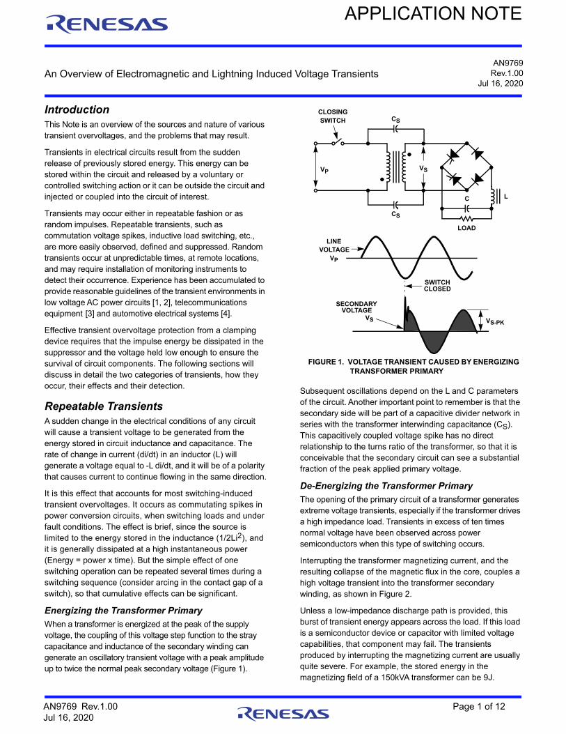
When a transformer is energized at the peak of the supply voltage, the coupling of this voltage step function to the stray capacitance and inductance of the secondary winding can generate an oscillatory transient voltage with a peak amplitude up to twice the normal peak secondary voltage (Figure 1).
Subsequent oscillations depend on the L and C parameters of the circuit. Another important point to remember is that the secondary side will be part of a capacitive divider network in series with the transformer interwinding capacitance (CS). This capacitively coupled voltage spike has no direct relationship to the turns ratio of the transformer, so that it is conceivable that the secondary circuit can see a substantial fraction of the peak applied primary voltage.
De-Energizing the Transformer Primary
The opening of the primary circuit of a transformer generates extreme voltage transients, especially if the transformer drives a high impedance load. Transients in excess of ten times normal voltage have been observed across power semiconductors when this type of switching occurs.
Interrupting the transformer magnetizing current, and the resulting collapse of the magnetic flux in the core, couples a high voltage transient into the transformer secondary winding, as shown in Figure 2.
Unless a low-impedance discharge path is provided, this burst of transient energy appears across the load. If this load is a semiconductor device or capacitor with limited voltage capabilities, that component may fail. The transients produced by interrupting the magnetizing current are usually quite severe. For example, the stored energy in the magnetizing field of a 150kVA transformer can be 9J.
LINEVOLTAGE
VP
SWITCHCLOSED
SECONDARYVOLTAGE
VS VS-PK
VP VS
LOAD
C
CLOSINGSWITCH CS
CS
L
FIGURE 1. VOLTAGE TRANSIENT CAUSED BY ENERGIZING TRANSFORMER PRIMARY
AN9769 Rev.1.00 Page 1 of 12Jul 16, 2020
An Overview of Electromagnetic and Lightning Induced Voltage Transients
Fault with Inductive Power Source
If a short develops on any power system, devices parallel to the load may be destroyed as the fuse clears.
When the fuse or circuit breaker of Figure 3 opens, it interrupts the fault currents causing the slightly inductive power source to generate a high voltage (-L di/dt), and high energy (1/2Li2), transient across any parallel devices. Suddenly interrupting a high current load will have a similar effect.
Switch Arcing
When current in an inductive circuit, such as a relay coil or a filter reactor, is interrupted by a contactor, the inductance tries to maintain its current by charging the stray capacitance. Similar action can take place during a closing sequence if the contacts bounce open after the initial closing as in Figure 4. The high initial charging current will oscillate in the inductance and capacitance at a high frequency. When the voltage at the
contact rises, breakdown of the gap is possible since the distance is still very small during the opening motion of the contact. The contact arc will clear at the current zero of the oscillation but it will restrike as the contact voltage rises again. As the contacts are moving farther apart, each restrike must occur at a higher and higher voltage until the contact succeeds in interrupting the current.
This restrike and escalation effect is particularly apparent in Figure 5, where a switch opens a relay coil of 1H, having about 0.001F of distributed (stray) capacitance in the winding. Starting with an initial DC current of a 100mA, the circuit produces hundreds of restrikes (hence, the “white” band on the oscillogram) at high repetition rate, until the circuit clears, but not before having reached a peak of 3kV in contrast to the initial 125V in the circuit.
Electromechanical contacts generate transients which they generally can survive. However, in the example just discussed, the 2.5ms long sequence of restrikes and attendant high current may be damaging to the contacts. Also, the transients injected into the power system during the restrike can be damaging to other loads.
In an attempt to eliminate electromechanical switches and their arcing problem, solid-state switches are recommended with good reason! However, if these switches are applied without discrimination in inductive circuits, the very effectiveness of the interruption can lead to the generation of high voltage transients.
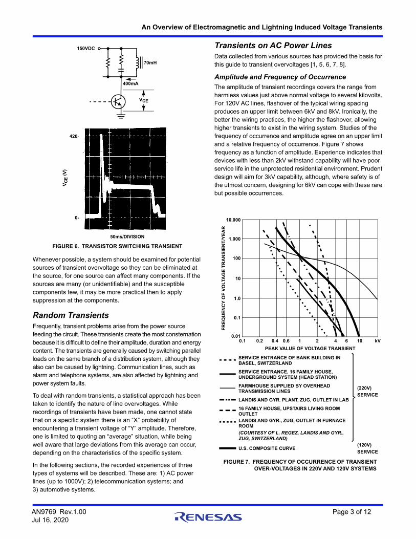
In the example of Figure 6, the transistor used for switching 400mA in a 70mH solenoid is exposed to 420V spikes, although the circuit voltage is only 150V.
LINEVOLTAGE
VP
MAGNETIZINGCURRENT iM
AND FLUX
SWITCHOPENED
VOLTAGETRANSIENTSECONDARY
VOLTAGE VS
VPVS
LOAD
CL
CLOSING SWITCH
iM
+ -
FIGURE 2. VOLTAGE TRANSIENT CAUSED BY INTERRUPTION OF TRANSFORMER MAGNETIZING CURRENT
OTHERLOAD
SHORT
SCRDAMAGED
(LOAD)
VSUPPLY
L
i
FIGURE 3. VOLTAGE TRANSIENT CAUSED BY FUSE BLOWING DURING POWER FAULT
tVSUPPLY
VCAP VLINE
SOLID-STATEEQUIPMENT
FIGURE 4. VOLTAGE TRANSIENTS CAUSED BY SWITCH
+
0
-
HORIZONTAL -t, 500s/DIV., VERTICAL -V, 1.0kV/DIV
FIGURE 5. VOLTAGE ESCALATION DURING RESTRIKES
AN9769 Rev.1.00 Page 2 of 12Jul 16, 2020
An Overview of Electromagnetic and Lightning Induced Voltage Transients
Whenever possible, a system should be examined for potential sources of transient overvoltage so they can be eliminated at the source, for one source can affect many components. If the sources are many (or unidentifiable) and the susceptible components few, it may be more practical then to apply suppression at the components.
Random TransientsFrequently, transient problems arise from the power source feeding the circuit. These transients create the most consternation because it is difficult to define their amplitude, duration and energy content. The transients are generally caused by switching parallel loads on the same branch of a distribution system, although they also can be caused by lightning. Communication lines, such as alarm and telephone systems, are also affected by lightning and power system faults.
To deal with random transients, a statistical approach has been taken to identify the nature of line overvoltages. While recordings of transients have been made, one cannot state that on a specific system there is an “X” probability of encountering a transient voltage of “Y” amplitude. Therefore, one is limited to quoting an “average” situation, while being well aware that large deviations from this average can occur, depending on the characteristics of the specific system.
In the following sections, the recorded experiences of three types of systems will be described. These are: 1) AC power lines (up to 1000V); 2) telecommunication systems; and 3) automotive systems.
Transients on AC Power LinesData collected from various sources has provided the basis for this guide to transient overvoltages [1, 5, 6, 7, 8].
Amplitude and Frequency of Occurrence
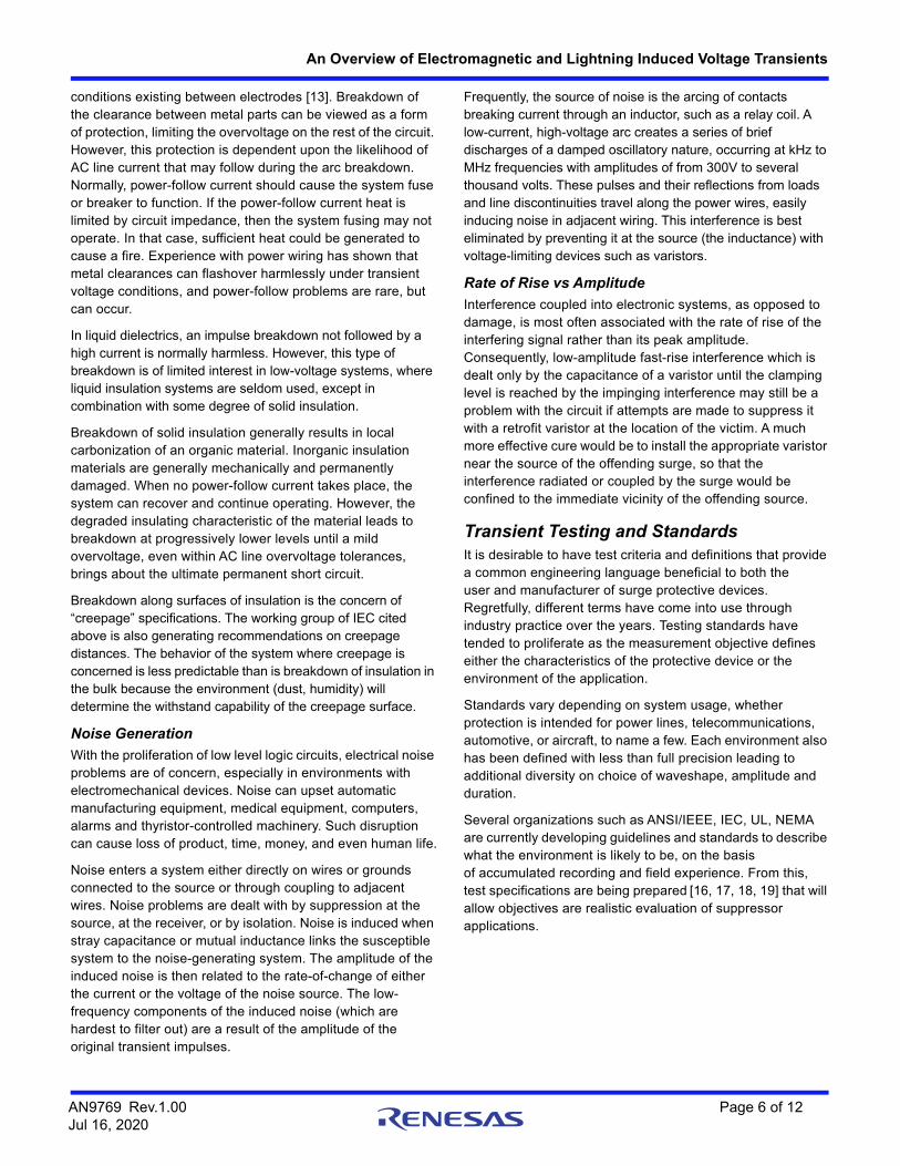
The amplitude of transient recordings covers the range from harmless values just above normal voltage to several kilovolts. For 120V AC lines, flashover of the typical wiring spacing produces an upper limit between 6kV and 8kV. Ironically, the better the wiring practices, the higher the flashover, allowing higher transients to exist in the wiring system. Studies of the frequency of occurrence and amplitude agree on an upper limit and a relative frequency of occurrence. Figure 7 shows frequency as a function of amplitude. Experience indicates that devices with less than 2kV withstand capability will have poor service life in the unprotected residential environment. Prudent design will aim for 3kV capability, although, where safety is of the utmost concern, designing for 6kV can cope with these rare but possible occurrences.
VCE
400mA
70mH
150VDC
420-
VC
E (
V)
0-
50ms/DIVISION
FIGURE 6. TRANSISTOR SWITCHING TRANSIENT
10,000
1,000
100
10
1.0
0.1
0.010.1 0.2 0.4 0.6 1 2 4 6 10 kV
PEAK VALUE OF VOLTAGE TRANSIENT
FR
EQ
UE
NC
Y O
F V
OLT
AG
E T
RA
NS
IEN
T/Y
EA
R
SERVICE ENTRANCE OF BANK BUILDING INBASEL, SWITZERLAND
SERVICE ENTRANCE, 16 FAMILY HOUSE,UNDERGROUND SYSTEM (HEAD STATION)
FARMHOUSE SUPPLIED BY OVERHEADTRANSMISSION LINES
LANDIS AND GYR. PLANT, ZUG, OUTLET IN LAB
16 FAMILY HOUSE, UPSTAIRS LIVING ROOMOUTLETLANDIS AND GYR., ZUG, OUTLET IN FURNACEROOM
(COURTESY OF L. REGEZ, LANDIS AND GYR.,ZUG, SWITZERLAND)
U.S. COMPOSITE CURVE
(220V)
SERVICE
(120V)
SERVICE
FIGURE 7. FREQUENCY OF OCCURRENCE OF TRANSIENT OVER-VOLTAGES IN 220V AND 120V SYSTEMS
AN9769 Rev.1.00 Page 3 of 12Jul 16, 2020
An Overview of Electromagnetic and Lightning Induced Voltage Transients
For systems of higher voltages (220V, 240V, 480V), limited data is available for U.S. systems. However, the curves of Figure 8 indicate the difference between the two classes, 120V and 220V systems, is smaller than the differences within each class [8]. One can conclude that the amplitude of the transient depends more upon the amount of externally coupled energy and the system impedance than upon the system voltage.
For internal switching transients in the power system, Figure 8 shows the relationship (computed and measured) between system voltage and transient peaks [8]. Clearly, there is no direct linear increase of the transient amplitude as the system voltage is increased.
Some indication of the uncertainty concerning the expected transient level can be found in the industrial practice of choosing semiconductor ratings. Most industrial users of power semiconductors choose semiconductor voltage ratings from 2.0 to 2.5 times the applied peak steady-state voltage, in conjunction with rudimentary transient suppression, in order to ensure long-term reliability. Whether or not this ratio is realistically related to actual transient levels has not been established; the safety factor is simply chosen by experience. While it is dangerous to argue against successful experience, there are enough cases where this rule of thumb is insufficient and thus a more exact approach is justified. Another objection to the indiscriminate rule of thumb is economic. Specifying 2.5 times the peak system voltage results in a high price penalty for these components. It is normally unrealistic and uneconomical to specify semiconductors that should withstand transients without protection. The optimum situation is a combination of low cost transient protection combined with lower cost semiconductors having lower voltage ratings.
Duration, Waveform and Source Impedance
There is a lack of definitive data on the duration, waveform and source impedance of transient overvoltages in AC power circuits. These three parameters are important for estimating the energy that a transient can deliver to a suppressor. It is desirable to have a means of simulating the environment through a model of the transient overvoltage pulse. Suggestions have been made to use standard impulses initially developed for other applications. For instance, the classical 1.2 x 50s unidirectional voltage impulse specified in high voltage systems has been proposed [9]. Also the repetitive burst of 1.5MHz oscillations (“SWC”) specified for low-voltage and control systems exposed to transients induced by high-voltage disconnect switches in utility switch yards is another suggestion [10].
Working Groups of the IEEE and the International Electrotechnical Commission have developed standard test waves and source impedance definitions. These efforts are aiming at moving away from a concept whereby one should duplicate environmental conditions and towards a concept of one standard wave or a few standard waves arbitrarily specified. The justifications are that equipments built to meet such standards have had satisfactory field experience and provide a relative standard against which different levels of protection can be compared. A condition for acceptance of these standard waves is that they be easy to produce in the laboratory [11]. This is the central idea of the TCL (Transient Control Level) concept which is currently being proposed to users and manufacturers in the electronics industry. Acceptance of this concept will increase the ability to test and evaluate the reliability of devices and systems at acceptable cost.
Telecommunication Line TransientsTransient overvoltages occurring in telephone lines can usually be traced to two main sources: lightning and 50Hz/60Hz power lines. Lightning overvoltage is caused by a strike to the conductor of an open wire system or to the shield of a telephone cable. Most modern telephone lines are contained in shielded cables. When lightning or other currents flow on the shield of a cable, voltages are induced between the internal conductors and the shield [12]. The magnitude of the induced voltages depend on the resistance of the shield material, openings in its construction, and on the dielectric characteristics and surge impedance of the cable.
The close proximity of telephone cables and power distribution systems, often sharing right-of-way-poles and even ground wires, is a source of transient overvoltages for the telephone system. Overvoltages can arise from physical contact of falling wires, electromagnetic induction, and ground potential rise. Application Note AN9774 presents a detailed discussion of lightning-induced and power system-induced transients.
6
5
4
3
2
1
0100 200 300 400 500
RATED VOLTAGE OF DISTRIBUTION SYSTEM (V)
TR
AN
SIE
NT
OV
ER
VO
LTA
GE
(k
V)
TH 5s TH 5s
TH 1000s
TN = TIME TO HALFVALUE OF PEAK
FIGURE 8. SWITCHING VOLTAGE TRANSIENTS vs THE SYSTEM VOLTAGE FOR THREE VALUES OF THE TRANSIENT TAIL (TIME TO HALF-VALUE) - (DATA COURTESY OF L. REGEZ, LANDIS AND GYR., ZAG, SWITZERLAND)
AN9769 Rev.1.00 Page 4 of 12Jul 16, 2020
An Overview of Electromagnetic and Lightning Induced Voltage Transients
Automobile TransientsFour principal types of voltage transients are encountered in an automobile. These are “load dump,” alternator field decay, inductive switching and mutual coupling [4]. In addition, service “Jump starts” with 24V batteries may occur.
The load dump transient is the most severe and occurs when the alternator current loading is abruptly reduced. The most demanding case is often initiated by the disconnection of a partially discharged battery due to defective terminal connections. Transient voltages have been reported over 100V lasting up to 500ms with energy levels in the range of tens to hundreds of joules.
Switching of inductive loads, such as motors and solenoids, will create negative polarity transient voltages with a smaller positive excursion. The voltage waveform has been observed to rise to a level of -210V and +80V and last as long as 320s. The impedance to the transient is unknown, leading some designers to test with very low impedance, resulting in the use of more expensive components than necessary.
The alternator field decay transient is essentially an inductive load switching transient. When the ignition switch is turned off, the decay of the alternator field produces a negative voltage spike, whose amplitude is dependent on the voltage regulator cycle and load. It varies between -40V to -100V and can last 200ms.
Application Note AN9312 provides a comprehensive review of automotive transients and practical suppression techniques to protect automotive electronics.
Effects of Voltage Transients
Effects on Semiconductors
Frequently, damage occurs when a high reverse voltage is applied to a nonconducting PN junction. The junction may avalanche at a small point due to the non-uniformity of the electric field. Also, excess leakage current can occur across the passivated junction between the terminations on the die surface. The current can create a low resistance channel that degrades the junction blocking voltage capability below the applied steady-state voltage. In the avalanche case, thermal runaway can occur because of localized heating building up to cause a melt-through which destroys the junction.
If the base-emitter junction of a transistor is repetitively “avalanched” or “zenered” to a high current level by a reverse pulse, the forward current gain may be degraded. The triggering sensitivity of a thyristor can be reduced in the same manner by “zenering” the gate-cathode junction. Thyristors can also be damaged if turned on by a high voltage spike (forward breakover) under bias conditions that allow a rate of current increase (di/dt) beyond device capability. This will occur in virtually all practical circuits because the discharge of the RC dv/dt protection circuits will exceed device capability for di/dt and destroy the thyristor.
Effects on Electromechanical Contacts
The high voltage generated by breaking current to an inductor with a mechanical switch will ultimately cause pitting, welding, material transfer, or erosion of the contacts. The nature of ultimate failure of the contacts depends upon such factors as the type of metal used, rate of opening, contact bounce, atmosphere, temperature, steady-state and inrush currents, and AC or DC operation. Perhaps most important is the amount of energy dissipated in each operation of the contacts.
The actual breaking of current by a set of contacts is a complex operation. The ultimate break occurs at a microscopic bridge of metal which, due to the inductive load, is forced to carry nearly all the original steady-state current. Ohmic heating of this bridge causes it to form a plasma, which will conduct current between the contacts when supplied with a current and voltage above a certain threshold. The inductor, of course, is more than happy to supply adequate voltage (EL = -L di/dt). As the contacts separate and the current decreases, a threshold is reached, and the current stops abruptly (“chopping”). Inductor current then charges stray capacitances up to the breakdown voltage of the atmosphere between the contacts. (For air, this occurs at 30kV/in.) The capacitance discharges and recharges repeatedly until all the energy is dissipated. This arc causes sufficient contact heating to melt, oxidize, or “burn” the metal, and when the contacts close again, the contacts may form a poorer connection. If they “bounce,” or are closed soon after arcing, the contacts may be sufficiently molten to weld closed. Welding can also occur as a result of high inrush currents passing through the initially formed bridges upon closing.
Good suppression techniques can significantly reduce the amount of energy dissipated at the contacts, with a proportional increase in operating life. Suppression can also reduce the noise generated by this arcing. Voltage-limiting devices are particularly suited to preventing the noisy high-voltage “showering” arc described above and illustrated in Figure 4.
Effects on Insulation
Transient overvoltages can cause breakdown of insulation, resulting in either a temporary disturbance of device operation or instantaneous failure. The insulating level in the former case will be weakened leading to premature failure.
The severity of the breakdown varies with the type of insulation air, liquid, or solid. The first two tend to be self-healing, while breakdown of solid insulation (generally organic materials) is generally a permanent condition.
Air clearances between metal parts in electrical devices and power wiring constitute air gaps, which behave according to the usual physics of gap breakdown (pressure, humidity, shape of electrodes, spacing). The International Electrotechnical Commission Working Group on Low Voltage Insulation Coordination has developed a table listing the minimum clearances in air for optimum and worst case electric field
AN9769 Rev.1.00 Page 5 of 12Jul 16, 2020
An Overview of Electromagnetic and Lightning Induced Voltage Transients
conditions existing between electrodes [13]. Breakdown of the clearance between metal parts can be viewed as a form of protection, limiting the overvoltage on the rest of the circuit. However, this protection is dependent upon the likelihood of AC line current that may follow during the arc breakdown. Normally, power-follow current should cause the system fuse or breaker to function. If the power-follow current heat is limited by circuit impedance, then the system fusing may not operate. In that case, sufficient heat could be generated to cause a fire. Experience with power wiring has shown that metal clearances can flashover harmlessly under transient voltage conditions, and power-follow problems are rare, but can occur.
In liquid dielectrics, an impulse breakdown not followed by a high current is normally harmless. However, this type of breakdown is of limited interest in low-voltage systems, where liquid insulation systems are seldom used, except in combination with some degree of solid insulation.
Breakdown of solid insulation generally results in local carbonization of an organic material. Inorganic insulation materials are generally mechanically and permanently damaged. When no power-follow current takes place, the system can recover and continue operating. However, the degraded insulating characteristic of the material leads to breakdown at progressively lower levels until a mild overvoltage, even within AC line overvoltage tolerances, brings about the ultimate permanent short circuit.
Breakdown along surfaces of insulation is the concern of “creepage” specifications. The working group of IEC cited above is also generating recommendations on creepage distances. The behavior of the system where creepage is concerned is less predictable than is breakdown of insulation in the bulk because the environment (dust, humidity) will determine the withstand capability of the creepage surface.
Noise Generation
With the proliferation of low level logic circuits, electrical noise problems are of concern, especially in environments with electromechanical devices. Noise can upset automatic manufacturing equipment, medical equipment, computers, alarms and thyristor-controlled machinery. Such disruption can cause loss of product, time, money, and even human life.
Noise enters a system either directly on wires or grounds connected to the source or through coupling to adjacent wires. Noise problems are dealt with by suppression at the source, at the receiver, or by isolation. Noise is induced when stray capacitance or mutual inductance links the susceptible system to the noise-generating system. The amplitude of the induced noise is then related to the rate-of-change of either the current or the voltage of the noise source. The low-frequency components of the induced noise (which are hardest to filter out) are a result of the amplitude of the original transient impulses.
Frequently, the source of noise is the arcing of contacts breaking current through an inductor, such as a relay coil. A low-current, high-voltage arc creates a series of brief discharges of a damped oscillatory nature, occurring at kHz to MHz frequencies with amplitudes of from 300V to several thousand volts. These pulses and their reflections from loads and line discontinuities travel along the power wires, easily inducing noise in adjacent wiring. This interference is best eliminated by preventing it at the source (the inductance) with voltage-limiting devices such as varistors.
Rate of Rise vs Amplitude
Interference coupled into electronic systems, as opposed to damage, is most often associated with the rate of rise of the interfering signal rather than its peak amplitude. Consequently, low-amplitude fast-rise interference which is dealt only by the capacitance of a varistor until the clamping level is reached by the impinging interference may still be a problem with the circuit if attempts are made to suppress it with a retrofit varistor at the location of the victim. A much more effective cure would be to install the appropriate varistor near the source of the offending surge, so that the interference radiated or coupled by the surge would be confined to the immediate vicinity of the offending source.
Transient Testing and StandardsIt is desirable to have test criteria and definitions that provide a common engineering language beneficial to both the user and manufacturer of surge protective devices. Regretfully, different terms have come into use through industry practice over the years. Testing standards have tended to proliferate as the measurement objective defines either the characteristics of the protective device or the environment of the application.
Standards vary depending on system usage, whether protection is intended for power lines, telecommunications, automotive, or aircraft, to name a few. Each environment also has been defined with less than full precision leading to additional diversity on choice of waveshape, amplitude and duration.
Several organizations such as ANSI/IEEE, IEC, UL, NEMA are currently developing guidelines and standards to describe what the environment is likely to be, on the basis of accumulated recording and field experience. From this, test specifications are being prepared [16, 17, 18, 19] that will allow objectives are realistic evaluation of suppressor applications.
AN9769 Rev.1.00 Page 6 of 12Jul 16, 2020
An Overview of Electromagnetic and Lightning Induced Voltage Transients
ReferencesFor Harris documents available on the internet, see web sitehttp://www.semi.harris.com/Harris AnswerFAX (407) 724-7800.
[1] Martzloff, F.D., “The Development of a Guide on Surge Voltages in Low-Voltage AC Power Circuits,” Report 81 CRD047, General Electric, Schenectady, New York 1981.
[2] Greenwood, Allan, “Electrical Transients in Power Systems”, Wiley-Interscience, New York, 1971.
[3] Bodle, D.W., A.J. Ghaze, M. Syed and R.L. Woodside, “Characterization of the Electrical Environment,” Toronto: University of Toronto Press, 1970.
[4] “Recommended Environmental Practices for Electronic Equipment Design,” Publication SAEJ1211, Society of Automotive Engineers, Warrendale, Pennsylvania.
[5] Hahn, G.J. and F.D. Martzloff, “Surge Voltages in Residential and Industrial Power Circuits,” IEEE Trans. PAS-89, No. 6, July-Aug. 1970, pp. 1049-1056.
[6] Bull, J.H., “Voltage Spikes in L. V. Distribution Systems and Their Effects on the Use of Electronic Control Equipment,” Report No. 5254, Electrical Research Assn., Cleeve Rd., Leatherhead, Surrey, Great Britain, 1968.
[7] EEE Surge Protective Devices Committee, “Bibliography on Surge Voltages in AC Power Circuits Rated 600 Volts or Less,” IEEE Trans. PAS-89, No. 6, July-Aug. 1970, pp. 1056-1061.
[8] Data contributed by L. Regez (Landis & Gyr. Co., Zug, Switzerland), Swiss representative to IEC Working Group 28A on Low Voltage Insulation Coordination.
[9] “Surge Arresters for Alternating Current Power Circuits,” ANSI Standard C62.1, IEEE Standard 28,1974.
[10] “Guide for Surge Withstand Capability (SWC) Test,” ANSl Standard C37.90a, 1974, IEEE Standard 472,1974.
[11] Martzloff, F.D. and F.A. Fisher, “Transient Control Level Philosophy and Implementation The Reasoning Behind the Philosophy,” 77CH1224-SEMC, Proceedings of the 2nd Symposium on EMC, Montreux, June 1977.
[12] Fisher, F.A., “A Way to Evaluate the Effects of Changing Magnetic Fields on Shielded Conductors,” Report 77CRD158, General Electric, Schenectady, New York, July 1977.
[13] “Insulation Coordination Within Low-Voltage Systems, including Clearances and Creepage Distances for Equipment,” IEC Report 664,1980.
[14] Allen, George W., “Design of Power-Line Monitoring Equipment,” IEEE Trans. PAS-90, No. 6, Nov-Dec. 1971, pp.2604-2609.
[15] Herzog, R., “How to Catch a Transient” Machine Design Magazine, March 1973, pp. 170-175.
[16] “IEEE Standard Test Specifications for Gas Tube Surge-Protective Devices,” ANSI/IEEE C62.3 1-1981.
[17] “IEEE Standard Test Specifications for Low-Voltage Air Gap Surge-Protective Devices (Excluding Valve and Expulsion Type Devices),” ANSI/IEEE C62.32- 1981.
[18] “IEEE Standard Test Specifications for Varistor Surge-Protective Devices,” ANSI/IEEE C62.33- 1982.
[19] “IEEE Standard Test Specifications for Avalanche Junction Semiconductor Surge-Protective Devices,” IEEE C62.34-1984.
AN9769 Rev.1.00 Page 7 of 12Jul 16, 2020
An Overview of Electromagnetic and Lightning Induced Voltage Transients
The Development of a Guide† on Surge Voltages in Low-Voltage AC Power Circuits
Introduction
Surge voltages occurring in AC power circuits can be the cause of misoperation or product failure for residential as well as industrial systems. The problem has received increased attention in recent years because miniaturized solid state devices are more sensitive to voltage surges (spikes and transients) than were their predecessors.
Although surge voltage amplitudes and their frequency of occurrence on unprotected circuits are well known, their waveshapes and energy content are less well known. On the basis of measurements, statistics, and theoretical considerations, a practical guide for outlining the environment for use in predicting extreme waveshapes and energy content can nevertheless be established. A Working Group of the Surge Protective Devices Committee has completed such a descriptive Guide.†† The Guide proposes two waveforms, one oscillatory, the other unidirectional, depending on the location within the power system. It also includes recommendations for source impedance or short-circuit current. While the major purpose of the Guide is to describe the environment, a secondary purpose is to lead toward standard tests.
The Origins of Surge Voltages
Surge voltages occurring in low-voltage AC power circuits originate from two major sources: system switching transients and direct or indirect lightning effects on the power system. System switching transients can be divided into transients associated with (1) major power system switching disturbances, such as capacitor bank switching; (2) minor switching near the point of interest, such as an appliance turnoff in a household or the turnoff of other loads in an individual system; (3) resonating circuits associated with switching devices, such as thyristors; and (4) various system faults, such as short circuits and arcing faults.
Measurements and calculations of lightning effects have been made to yield data on what levels can be produced, even if the exact mechanism of any particular surge is unknown. While the data have been recorded primarily on 120, 220/380, or 277/480V systems, the general conclusions should be valid for 600V systems. To the extent that surge voltages are produced by a discrete amount of energy being dumped into a power system, low impedance, heavy industrial systems can be expected to experience lower peaks from surge voltages than 120V residential systems, but comparable, or greater, amounts of energy potentially available for deposition in a surge suppressor.
Rate of Occurrence and Voltage Levels In Unprotected Circuits
The rate of occurrence of surges varies over wide limits, depending on the particular power system. Prediction of the rate for a particular system is always difficult and frequently impossible. Rate is related to the level of the surges; low-level surges are more prevalent than high-level surges.
It is essential to recognize that a surge voltage observed in a power system can be either the driving voltage or the voltage limited by the sparkover of some clearance in the system. Hence, the term unprotected circuit must be understood to be a circuit in which no low-voltage protective device has been installed but in which clearance sparkover will eventually limit the maximum voltage. The distribution of surge levels, therefore, is influenced by the surge-producing mechanisms as well as by the sparkover level or clearances in the system. This distinction between actual driving voltage and voltage limited by sparkover is particularly important at the interface between outdoor equipment and indoor equipment. Outdoor equipment has generally higher clearances, hence higher sparkover levels: 10kV may be typical, but 20kV is possible. In contrast, most indoor wiring devices used in 120V-240V systems have sparkover levels of about 6kV; this 6kV level, therefore, can be selected as a typical cutoff for the occurrence of surges in indoor power systems.
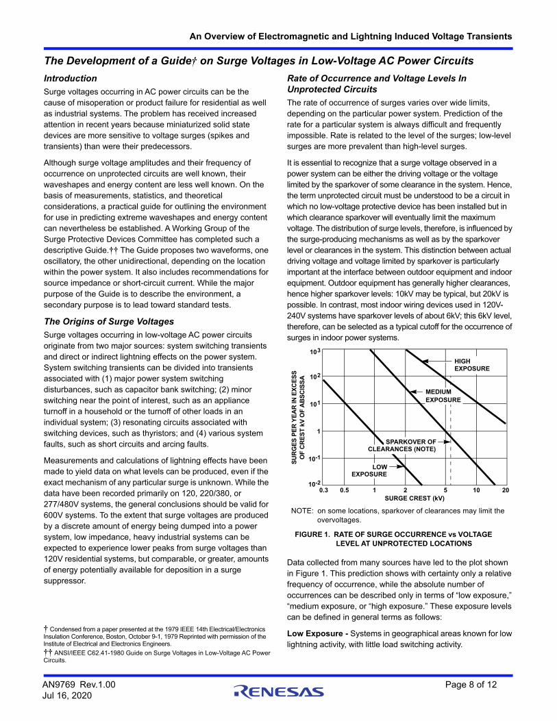
Data collected from many sources have led to the plot shown in Figure 1. This prediction shows with certainty only a relative frequency of occurrence, while the absolute number of occurrences can be described only in terms of “low exposure,” “medium exposure, or “high exposure.” These exposure levels can be defined in general terms as follows:
Low Exposure - Systems in geographical areas known for low lightning activity, with little load switching activity.
103
102
101
1
10-1
10-20.3 0.5 1 2 5 10 20
LOWEXPOSURE
MEDIUMEXPOSURE
HIGHEXPOSURE
SURGE CREST (kV)
SU
RG
ES
PE
R Y
EA
R IN
EX
CE
SS
OF
CR
ES
T k
V O
F A
BS
CIS
SA
NOTE: on some locations, sparkover of clearances may limit the overvoltages.
FIGURE 1. RATE OF SURGE OCCURRENCE vs VOLTAGE LEVEL AT UNPROTECTED LOCATIONS
SPARKOVER OFCLEARANCES (NOTE)
† Condensed from a paper presented at the 1979 IEEE 14th Electrical/Electronics Insulation Conference, Boston, October 9-1, 1979 Reprinted with permission of the Institute of Electrical and Electronics Engineers.
†† ANSI/IEEE C62.41-1980 Guide on Surge Voltages in Low-Voltage AC Power Circuits.
AN9769 Rev.1.00 Page 8 of 12Jul 16, 2020
An Overview of Electromagnetic and Lightning Induced Voltage Transients
Medium Exposure - Systems in geographical areas known for high lightning activity, with frequent and severe switching transients.
High Exposure - Rare but real systems supplied by long overhead lines and subject to reflections at line ends, where the characteristics of the installation produce high sparkover levels of the clearances.
The two lower lines of Figure 1 have been drawn at the same slope, since the data base shows reasonable agreement among several sources on that slope. All lines may be truncated by sparkover of the clearances at levels depending on the withstand voltage of these clearances. The “high-exposure” line needs to be recognized, but it should not be applied indiscriminately to all systems. Such application would penalize the majority of installations, where the exposure is lower.
From the relative values of Figure 1, two typical levels can be cited for practical applications. First, the expectation 3kV transient occurrence on a 120V circuit ranges from 0.01 to 10 per year at a given location a number sufficiently high to justify the recommendation of a minimum 3kV withstand capability. Second, the sparkover of wiring devices indicates that a 6kV withstand capability may be sufficient to ensure device survival indoors, but a withstand capability of 10kV, or greater, may be required outdoors.
The voltage and current amplitudes presented in the Guide attempt to provide for the vast majority of lightning strikes but should not be considered as “worst case,” since this concept cannot be determined realistically. One should think in terms of the statistical distribution of strikes, accepting a reasonable upper limit for most cases. Where the consequences of a failure are not catastrophic but merely represent an annoying economic loss, it is appropriate to make a trade-off of the cost of protection against the likelihood of failure caused by a high but rare surge. For instance, a manufacturer may be concerned with nationwide failure rates, those at the upper limits of the distribution curve, while the user of a specific system may be concerned with a single failure occurring at a specific location under “worst-case conditions.” Rates can be estimated for average systems, however, and even if imprecise, they provide manufacturers and users with guidance. Of equal importance is the observation that surges in the range of 1kV to 2kV are fairly common in residential circuits.
Surges occur at random times with respect to the power frequency, and the failure mode of equipment may be affected by the power frequency follow current. Furthermore, the timing of the surge with respect to the power frequency may affect the level at which failure occurs. Consequently, when the failure mode is likely to be affected, surge testing should be done with the line voltage applied to the test piece.
Waveshape of Representative Surge Voltages
Waveshapes in Actual Occurrences
Indoor - Measurements in the field, measurements in the laboratory, and theoretical calculations indicate that most surge voltages in indoor low-voltage systems have oscillatory waveshapes, unlike the well-known and generally accepted unidirectional waves specified in high-voltage insulation standards. A surge impinging on the system excites the natural resonant frequencies of the conductor system. As a result, not only are the surges typically oscillatory, but surges may have different amplitudes and waveshapes at different places in the system. These oscillatory frequencies of surges range from 5kHz to more than 500kHz. A 30kHz to 100kHz frequency is a realistic measure of a “typical” surge for most residential and light industrial AC line networks.
Outdoor and Service Entrance - Surges encountered in outdoor locations have also been recorded, some oscillatory, other unidirectional. The “classical lightning surge” has been established as 1.2/50ms for a voltage wave and 8/20ms for a current wave, but these waveshapes should not be construed as typical waves for low-voltage circuits. Lightning discharges induce oscillations, reflections, and disturbances that ultimately appear as decaying oscillations in low-voltage systems.
Because the prime concern here is the energy associated with these surges, the waveshape to be selected must involve greater energy than that associated with the indoor environment. Secondary surge arresters have a long history of successful performance, meeting the ANSI C62.1 specification, as detailed below; consequently, these specifications can be adopted as a realistic representation of outdoor waveshapes.
Selection of Representative Waveshapes
The definition of a waveshape to be used as representative of the environment is important for the design of candidate protective devices, since unrealistic requirements, such as excessive duration of the voltage or very low source impedance, place a high energy requirement on the suppressor, with a resulting cost penalty to the end user. The two requirements defined below reflect this trade-off.
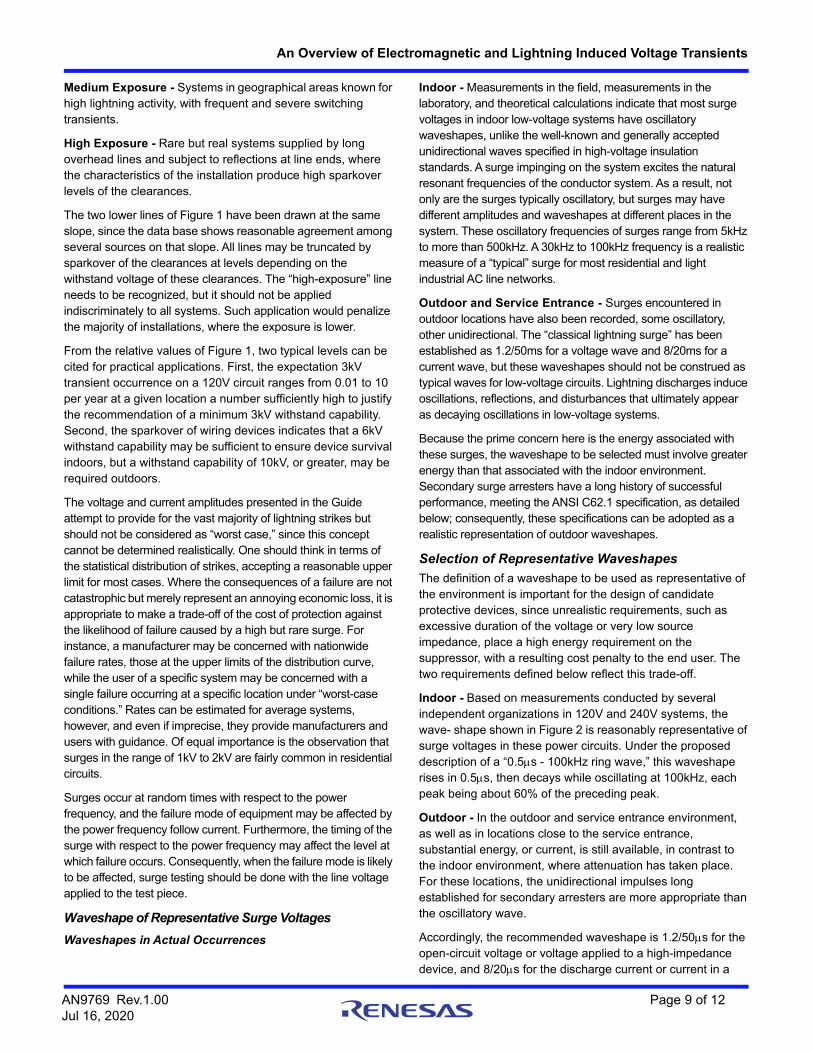
Indoor - Based on measurements conducted by several independent organizations in 120V and 240V systems, the wave- shape shown in Figure 2 is reasonably representative of surge voltages in these power circuits. Under the proposed description of a “0.5s - 100kHz ring wave,” this waveshape rises in 0.5s, then decays while oscillating at 100kHz, each peak being about 60% of the preceding peak.
Outdoor - In the outdoor and service entrance environment, as well as in locations close to the service entrance, substantial energy, or current, is still available, in contrast to the indoor environment, where attenuation has taken place. For these locations, the unidirectional impulses long established for secondary arresters are more appropriate than the oscillatory wave.
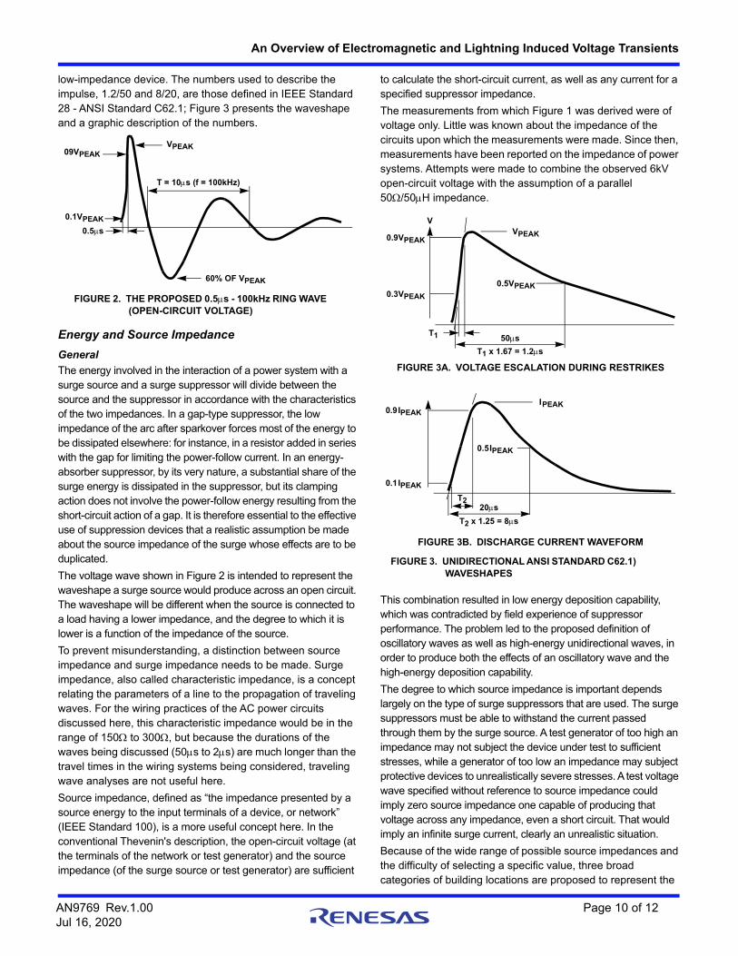
Accordingly, the recommended waveshape is 1.2/50s for the open-circuit voltage or voltage applied to a high-impedance device, and 8/20s for the discharge current or current in a
AN9769 Rev.1.00 Page 9 of 12Jul 16, 2020
An Overview of Electromagnetic and Lightning Induced Voltage Transients
low-impedance device. The numbers used to describe the impulse, 1.2/50 and 8/20, are those defined in IEEE Standard 28 - ANSI Standard C62.1; Figure 3 presents the waveshape and a graphic description of the numbers.
Energy and Source Impedance
General
The energy involved in the interaction of a power system with a surge source and a surge suppressor will divide between the source and the suppressor in accordance with the characteristics of the two impedances. In a gap-type suppressor, the low impedance of the arc after sparkover forces most of the energy to be dissipated elsewhere: for instance, in a resistor added in series with the gap for limiting the power-follow current. In an energy-absorber suppressor, by its very nature, a substantial share of the surge energy is dissipated in the suppressor, but its clamping action does not involve the power-follow energy resulting from the short-circuit action of a gap. It is therefore essential to the effective use of suppression devices that a realistic assumption be made about the source impedance of the surge whose effects are to be duplicated.
The voltage wave shown in Figure 2 is intended to represent the waveshape a surge source would produce across an open circuit. The waveshape will be different when the source is connected to a load having a lower impedance, and the degree to which it is lower is a function of the impedance of the source.
To prevent misunderstanding, a distinction between source impedance and surge impedance needs to be made. Surge impedance, also called characteristic impedance, is a concept relating the parameters of a line to the propagation of traveling waves. For the wiring practices of the AC power circuits discussed here, this characteristic impedance would be in the range of 150 to 300, but because the durations of the waves being discussed (50s to 2s) are much longer than the travel times in the wiring systems being considered, traveling wave analyses are not useful here.
Source impedance, defined as “the impedance presented by a source energy to the input terminals of a device, or network” (IEEE Standard 100), is a more useful concept here. In the conventional Thevenin's description, the open-circuit voltage (at the terminals of the network or test generator) and the source impedance (of the surge source or test generator) are sufficient
to calculate the short-circuit current, as well as any current for a specified suppressor impedance.
The measurements from which Figure 1 was derived were of voltage only. Little was known about the impedance of the circuits upon which the measurements were made. Since then, measurements have been reported on the impedance of power systems. Attempts were made to combine the observed 6kV open-circuit voltage with the assumption of a parallel 50/50H impedance.
This combination resulted in low energy deposition capability, which was contradicted by field experience of suppressor performance. The problem led to the proposed definition of oscillatory waves as well as high-energy unidirectional waves, in order to produce both the effects of an oscillatory wave and the high-energy deposition capability.
The degree to which source impedance is important depends largely on the type of surge suppressors that are used. The surge suppressors must be able to withstand the current passed through them by the surge source. A test generator of too high an impedance may not subject the device under test to sufficient stresses, while a generator of too low an impedance may subject protective devices to unrealistically severe stresses. A test voltage wave specified without reference to source impedance could imply zero source impedance one capable of producing that voltage across any impedance, even a short circuit. That would imply an infinite surge current, clearly an unrealistic situation.
Because of the wide range of possible source impedances and the difficulty of selecting a specific value, three broad categories of building locations are proposed to represent the
09VPEAKVPEAK
0.1VPEAK
0.5s
60% OF VPEAK
T = 10s (f = 100kHz)
FIGURE 2. THE PROPOSED 0.5s - 100kHz RING WAVE (OPEN-CIRCUIT VOLTAGE)
V
0.9VPEAK
0.3VPEAK
VPEAK
0.5VPEAK
50sT1
T1 x 1.67 = 1.2s
FIGURE 3A. VOLTAGE ESCALATION DURING RESTRIKES
T2 x 1.25 = 8s
0.9IPEAK
0.1IPEAK
T220s
0.5IPEAK
IPEAK
FIGURE 3B. DISCHARGE CURRENT WAVEFORM
FIGURE 3. UNIDIRECTIONAL ANSI STANDARD C62.1) WAVESHAPES
AN9769 Rev.1.00 Page 10 of 12Jul 16, 2020
An Overview of Electromagnetic and Lightning Induced Voltage Transients
vast majority of locations, from those near the service entrance to those remote from it. The source impedance of the surge increases from the outside to locations well within the building. Open-circuit voltages, on the other hand, show little variation within a building because the wiring provides little attenuation. Figure 4 illustrates the application of the three categories to the wiring of a building.
For the two most common location categories, Table 1 shows the representative surge voltages and currents, with the waveforms and amplitudes of the surges, and high- or low-impedance specimen. For the discharge current shown, the last two columns show the energy that would be deposited in a suppressor clamping at 500V and 1000V, typical of 120V or 240V applications, respectively. For higher system voltages (assuming the same current values), the energy would increase in proportion to the clamping voltage of a suppressor suitable for that system voltage.
The values shown in Table 1 represent the maximum range and correspond to the “medium exposure” situation of Figure 1. For less exposed systems, or when the prospect of a failure is not highly objectionable, one could specify lower values of open-circuit voltages with corresponding reductions in the discharge currents.
The 6kV open-circuit voltage derives from two facts: the limiting action of wiring device sparkover and the unattenuated propagation of voltages in unloaded systems. The 3kA discharge current in Category B derives from experimental results: field experience in suppressor performance and simulated lightning tests. The two levels of discharge currents from the 0.5s - 100kHz wave derive from the increasing impedance expected in moving from Category B to Category A.
Location Category C is likely to be exposed to substantially higher voltages than location Category B because the limiting effect of sparkover is not available. The “medium exposure” rates of Figure
1 could apply, with voltage in excess of 10kV and discharge currents of 10kA, or more. Installing unprotected load equipment in location Category C is not recommended; the installation of secondary arresters, however, can provide the necessary protection. Secondary arresters having 10kA ratings have been applied successfully for many years in location Category C (ANSI Standards C62.1 and C62.2).
A B C
NOTES:
A Outlets and Long Branch Circuits: All outlets at more than 10m(30 feet) from Category B with wires #14-10; All outlets at more than20m (60 feet) from Category C with wires #14-10.
B. Major Feeders and Short Branch Circuits: Distribution paneldevices; Bus and feeder systems in industrial plants; Heavyappliance outlets with “short” connections to the serviceentrance; Lighting systems in commercial.
C. Outside and Service Entrance: Service drop from pole tobuilding entrance; Run between meter and distribution panel;Overhead line to detached buildings; Underground lines to wellpumps.
FIGURE 4. LOCATION CATEGORIES
TABLE 1. SURGE VOLTAGES AND CURRENT DEEMED TO REPRESENT THE INDOOR ENVIRONMENT AND SUGGESTED FOR CONSIDERATION IN DESIGNING PROTECTIVE SYSTEMS
LOCATIONCATEGORY
COMPARABLETO IEC 664 CATEGORY
IMPULSE
TYPE OF SPECIMENOR LOAD CIRCUIT
ENERGY (JOULES) DEPOSITED IN A SUPPRESSOR (NOTE 6) WITH
CLAMPING VOLTAGE OF
WAVEFORM
MEDIUMEXPOSUREAMPLITUDE
500V(120V SYSTEM)
1000V(240V SYSTEM)
A.Long branch circuits and outlets
II 0.5ms - 100kHz 6kV High Impedance (Note 4) - -
200A Low Impedance (Note 5) 0.8 1.6
B.Major feeders short branch circuits, and load center
III 1.2/50s 6kV High Impedance (Note 4) - -
8/20s 3kA Low Impedance (Note 5) 40 80
0.5ms - 100kHz 6kV Low Impedance (Note 4) - -
500A High Impedance (Note 5) 2 4
NOTES:4. For high-impedance test specimens or load circuits, the voltage shown represents the surge voltage. In making simulation tests, use that value
for the open-circuit voltage of the test generator.5. For low-impedance test specimens or load circuits, the current shown represents the discharge current of the surge (not the short-circuit current
of the power system). In making simulation tests, use that current for the short-circuit current of the test generator.6. Other suppressors which have different clamping voltages would receive different energy levels.
AN9769 Rev.1.00 Page 11 of 12Jul 16, 2020
An Overview of Electromagnetic and Lightning Induced Voltage Transients
Revision HistoryThe revision history provided is for informational purposes only and is believed to be accurate, but not warranted. Please visit our website to make sure you have the latest revision.
DATE REVISION CHANGE
Jul 16, 2020 1.00 Applied Renesas Header/FooterAdded Revision History
AN9769 Rev.1.00 Page 12 of 12Jul 16, 2020
Corporate HeadquartersTOYOSU FORESIA, 3-2-24 Toyosu,Koto-ku, Tokyo 135-0061, Japanwww.renesas.com
Contact InformationFor further information on a product, technology, the most up-to-date version of a document, or your nearest sales office, please visit:www.renesas.com/contact/
TrademarksRenesas and the Renesas logo are trademarks of Renesas Electronics Corporation. All trademarks and registered trademarks are the property of their respective owners.
IMPORTANT NOTICE AND DISCLAIMER
RENESAS ELECTRONICS CORPORATION AND ITS SUBSIDIARIES (“RENESAS”) PROVIDES TECHNICAL SPECIFICATIONS AND RELIABILITY DATA (INCLUDING DATASHEETS), DESIGN RESOURCES (INCLUDING REFERENCE DESIGNS), APPLICATION OR OTHER DESIGN ADVICE, WEB TOOLS, SAFETY INFORMATION, AND OTHER RESOURCES “AS IS” AND WITH ALL FAULTS, AND DISCLAIMS ALL WARRANTIES, EXPRESS OR IMPLIED, INCLUDING, WITHOUT LIMITATION, ANY IMPLIED WARRANTIES OF MERCHANTABILITY, FITNESS FOR A PARTICULAR PURPOSE, OR NON-INFRINGEMENT OF THIRD PARTY INTELLECTUAL PROPERTY RIGHTS.
These resources are intended for developers skilled in the art designing with Renesas products. You are solely responsible for (1) selecting the appropriate products for your application, (2) designing, validating, and testing your application, and (3) ensuring your application meets applicable standards, and any other safety, security, or other requirements. These resources are subject to change without notice. Renesas grants you permission to use these resources only for development of an application that uses Renesas products. Other reproduction or use of these resources is strictly prohibited. No license is granted to any other Renesas intellectual property or to any third party intellectual property. Renesas disclaims responsibility for, and you will fully indemnify Renesas and its representatives against, any claims, damages, costs, losses, or liabilities arising out of your use of these resources. Renesas' products are provided only subject to Renesas' Terms and Conditions of Sale or other applicable terms agreed to in writing. No use of any Renesas resources expands or otherwise alters any applicable warranties or warranty disclaimers for these products.


![Lightning Surge Analysis by EMTP and Mumerical Electromagnetic Analysis Method[1]](https://static.documents.pub/doc/80x56/547599dcb4af9fc30a8b5b28/lightning-surge-analysis-by-emtp-and-mumerical-electromagnetic-analysis-method1.jpg)


![[1] Methods for Calculating Electromagnetic Fields From a Known Source Distribution Application to Lightning](https://static.documents.pub/doc/80x56/55cf9cdf550346d033ab5ab4/1-methods-for-calculating-electromagnetic-fields-from-a-known-source-distribution.jpg)


