Anal. Chem. 1990, 62, 2385-2387 2385 Spatially Resolved Laser Transfer of Organic Surface Films for Infrared Analysis M. S. de Vries, H. E. Hunziker,* and H. R. Wendt Almaden Research Center, IBM Research Division, San Jose, California 95120 D. D. Saperstein IBM General Products Diuision, San Jose, California 95193 The technique of laser transfer sampling is described and applied to obtain IR spectra of organic surface flbns. Spatially resolved transfer across a vacuum gap is demonstrated at 1064 and 248 nm, occurring by different, highly directional mechanisms. Laser interference in the gap and surface to- pography of the sample are shown to modulate the transfer- red film patterns. INTRODUCTION Chemical analysis of thin surface films is a task frequently encountered in areas such as the microelectronics industry and environmental monitoring. Intentionally deposited coatings as well as contamination layers need to be charac- terized. For molecular identification of organic layers the selection of techniques is rather limited. IR spectroscopy is often preferred because it is specific, quantitative, and non- destructive. It can, however, rarely be applied in situ: Dif- ficulties arise when the substrate is highly IR absorbing or has metallic reflection (only absorptions with transition mo- ment perpendicular to the surface are seen, requiring grazing incidence which limits spatial resolution) or if for some other reason an object cannot be directly examined with an IR spectrometer. In all these cases a sampling technique is de- sirable that separates the organic film from the substrate before analysis. This paper presents such a technique, which we call laser transfer sampling. We have used laser transfer sampling with some success for analyzing contaminants and lubricants on parts of data storage devices. The principle of the method is shown in Figure 1: A transfer target substrate is mounted close to the surface to be analyzed, separated from it by a vacuum gap. Transfer without a gap at ambient pressure may be feasible, but we have not investigated this possibility. This substrate is transparent for both IR and the laser wavelength used for transfer. A single laser pulse applied through it vaporizes all or part of the surface film and drives it across the gap onto the target. The latter is then dismounted and subjected to transmission IR analysis. This sampling techniques has the advantage of preserving some or all of the spatial information about the surface de- posit, as indicated by the transferred pattern in Figure l. Thus one can examine the transferred pattern with an IR micro- scope and recover the spatial distribution present on the original sample. The main purpose of this paper is to char- acterize the transfer of patterns and its limitations in detail. The results provide a basis for applications and shed some light on the transfer mechanism. Laser transfer of organic films for other purposes and without spatial imaging has been described in the literature. * To whom correspondence should be addressed. UV laser ablation of polymer films (1) and partial vaporization of frozen DNA solutions with 581-nm laser pulses (2) were found to be highly directional processes. Transfer of dust (3) and ice (2) particles driven by laser vaporization of water has also been observed. A theoretical analysis of the strongly forward-peaked expansion plumes encountered in laser sputtering has been given by Kelly (4). The technique de- scribed here is suitable for obtaining spatially resolved transfer samples from large or stationary objects by appropriate modification of the basic device shown in Figure 1. It suffices that a vacuum seal can be made against the surface to be examined. Transfer sampling may also be useful with ana- lytical techniques other than IR, where special substrates are required to give optimal results. Examples include secondary ion mass spectrometry (SIMS) (5) (Ag substrate), surface photoionization mass spectrometry (6) (Au substrate), scan- ning electron microscopy (SEM), and scanning tunneling microscopy. EXPERIMENTAL SECTION Coronene was chosen as the test substance for pattern transfer experiments. It has negligible vapor pressure at room temperature (p < W2 Torr), yet was conveniently vapor-deposited under vacuum Torr) from a crucible heated to about 225 "C. A mask with a lithography test pattern was pressed against the stainless steel and KBr sample substrates during evaporation, producing a patterned film as shown in Figure 3a. The micro- graphs of Figures 3 and 4 were obtained by using the fluorescence of coronene under UV illumination. Film thicknesses were measured during evaporation with a quartz crystal balance. The apparatus used for transfer is shown in Figure 1. Standard 25 mm diameter NaCl windows were used as transfer targets. Some visible coloration due to color centers appeared when using 248-nm laser pulses for transfer, but did not interfere with IR analysis of coronene deposits. A 0.25-mm vacuum gap between the sample and target was maintained by a spacer. Forepump vacuum of about 50 mTorr was sufficient to make the mean free path of vaporized molecules larger than the gap width. The vacuum also served to press and seal the transfer target plate against an O-ring, which made it easy to remove. A complete transfer experiment took no longer than 1 to 2 min including pump-down. Two different lasers were used to effect the transfers: a Nd:YAG system (1064 nm) with 10-ns pulse duration and max- imum fluence of 400 mJ/cm2,and a KrF exciplex laser (248 nm) with 25-ns pulse duration and 250 mJ/cm2 maximum fluence. Because the beam profile of the Nd:YAG laser is very inhomo- geneous at the laser exit, the transfer experiments were set up 10 m away in the far field where the profile is more even. The exciplex laser was operated with the unstable resonator cavity, which produces a beam profile (approximately 0.5 X 2.0 cm) much more uniform than that of the Nd:YAG laser. Figure 2 compares the Fourier transform infrared (FTIR) spectra of an original coronene film with one that was transferred with a 1064-nm pulse. Obviously no decomposition occurs due to the transfer process. The same observation was made at the 248-nm transfer wavelength. Two strong IR absorption bands 0003-2700/90/0362-2385$02SO/O 0 1990 American Chemical Society
Transcript
Anal. Chem. 1990, 62, 2385-2387 2385
Spatially Resolved Laser Transfer of Organic Surface Films for Infrared Analysis
M. S. de Vries, H. E. Hunziker,* and H. R. Wendt
Almaden Research Center, IBM Research Division, S a n Jose, California 95120
D. D. Saperstein
IBM General Products Diuision, S a n Jose, California 95193
The technique of laser transfer sampling is described and applied to obtain IR spectra of organic surface flbns. Spatially resolved transfer across a vacuum gap is demonstrated at 1064 and 248 nm, occurring by different, highly directional mechanisms. Laser interference in the gap and surface to- pography of the sample are shown to modulate the transfer- red film patterns.
INTRODUCTION Chemical analysis of thin surface films is a task frequently
encountered in areas such as the microelectronics industry and environmental monitoring. Intentionally deposited coatings as well as contamination layers need to be charac- terized. For molecular identification of organic layers the selection of techniques is rather limited. IR spectroscopy is often preferred because it is specific, quantitative, and non- destructive. I t can, however, rarely be applied in situ: Dif- ficulties arise when the substrate is highly IR absorbing or has metallic reflection (only absorptions with transition mo- ment perpendicular to the surface are seen, requiring grazing incidence which limits spatial resolution) or if for some other reason an object cannot be directly examined with an IR spectrometer. In all these cases a sampling technique is de- sirable that separates the organic film from the substrate before analysis. This paper presents such a technique, which we call laser transfer sampling.
We have used laser transfer sampling with some success for analyzing contaminants and lubricants on parts of data storage devices. The principle of the method is shown in Figure 1: A transfer target substrate is mounted close to the surface to be analyzed, separated from it by a vacuum gap. Transfer without a gap at ambient pressure may be feasible, but we have not investigated this possibility. This substrate is transparent for both IR and the laser wavelength used for transfer. A single laser pulse applied through it vaporizes all or part of the surface film and drives it across the gap onto the target. The latter is then dismounted and subjected to transmission IR analysis.
This sampling techniques has the advantage of preserving some or all of the spatial information about the surface de- posit, as indicated by the transferred pattern in Figure l. Thus one can examine the transferred pattern with an IR micro- scope and recover the spatial distribution present on the original sample. The main purpose of this paper is to char- acterize the transfer of patterns and its limitations in detail. The results provide a basis for applications and shed some light on the transfer mechanism.
Laser transfer of organic films for other purposes and without spatial imaging has been described in the literature.
* To whom correspondence should be addressed.
UV laser ablation of polymer films (1) and partial vaporization of frozen DNA solutions with 581-nm laser pulses (2) were found to be highly directional processes. Transfer of dust (3) and ice (2) particles driven by laser vaporization of water has also been observed. A theoretical analysis of the strongly forward-peaked expansion plumes encountered in laser sputtering has been given by Kelly (4). The technique de- scribed here is suitable for obtaining spatially resolved transfer samples from large or stationary objects by appropriate modification of the basic device shown in Figure 1. It suffices that a vacuum seal can be made against the surface to be examined. Transfer sampling may also be useful with ana- lytical techniques other than IR, where special substrates are required to give optimal results. Examples include secondary ion mass spectrometry (SIMS) (5) (Ag substrate), surface photoionization mass spectrometry (6) (Au substrate), scan- ning electron microscopy (SEM), and scanning tunneling microscopy.
EXPERIMENTAL SECTION Coronene was chosen as the test substance for pattern transfer
experiments. It has negligible vapor pressure at room temperature ( p < W2 Torr), yet was conveniently vapor-deposited under vacuum Torr) from a crucible heated to about 225 "C. A mask with a lithography test pattern was pressed against the stainless steel and KBr sample substrates during evaporation, producing a patterned film as shown in Figure 3a. The micro- graphs of Figures 3 and 4 were obtained by using the fluorescence of coronene under UV illumination. Film thicknesses were measured during evaporation with a quartz crystal balance.
The apparatus used for transfer is shown in Figure 1. Standard 25 mm diameter NaCl windows were used as transfer targets. Some visible coloration due to color centers appeared when using 248-nm laser pulses for transfer, but did not interfere with IR analysis of coronene deposits. A 0.25-mm vacuum gap between the sample and target was maintained by a spacer. Forepump vacuum of about 50 mTorr was sufficient to make the mean free path of vaporized molecules larger than the gap width. The vacuum also served to press and seal the transfer target plate against an O-ring, which made it easy to remove. A complete transfer experiment took no longer than 1 to 2 min including pump-down.
Two different lasers were used to effect the transfers: a Nd:YAG system (1064 nm) with 10-ns pulse duration and max- imum fluence of 400 mJ/cm2, and a KrF exciplex laser (248 nm) with 25-ns pulse duration and 250 mJ/cm2 maximum fluence. Because the beam profile of the Nd:YAG laser is very inhomo- geneous at the laser exit, the transfer experiments were set up 10 m away in the far field where the profile is more even. The exciplex laser was operated with the unstable resonator cavity, which produces a beam profile (approximately 0.5 X 2.0 cm) much more uniform than that of the Nd:YAG laser.
Figure 2 compares the Fourier transform infrared (FTIR) spectra of an original coronene film with one that was transferred with a 1064-nm pulse. Obviously no decomposition occurs due to the transfer process. The same observation was made at the 248-nm transfer wavelength. Two strong IR absorption bands
0003-2700/90/0362-2385$02SO/O 0 1990 American Chemical Society
2386 ANALYTICAL CHEMISTRY, VOL. 62. NO. 21. NOVEMBER 1, 1990
A n
IR abs. spectrum
Flgure 1. Schematic representation of the laser transfer technique. as applied for obtaining transmission IR spectra of patlerned wganic films
- o w m J . . . . , . . . . , . , , . " L zwo 15m ?om 5m
Warmumber ("7,
Flgure 2. IR spectra of wronene (a) in KBr and (b) 54 nm thick film transferred wim cne 1064-m laser pulse from stainless steel substrate l o NaCl target: resolution. 2 cm-'.
of coronene at E45 and 1314 em-' can readily be oberved at 1-nm f i lm thickness, in the 50 X 50 pm2 minimum area which can be resolved with the F T I R microscope attachment (Bruker IRIS5 or IR/44 with a high gain M C T detector).
RESULTS (a) 1064.111~ Laser, Sta in less Steel Subst rate. Figure
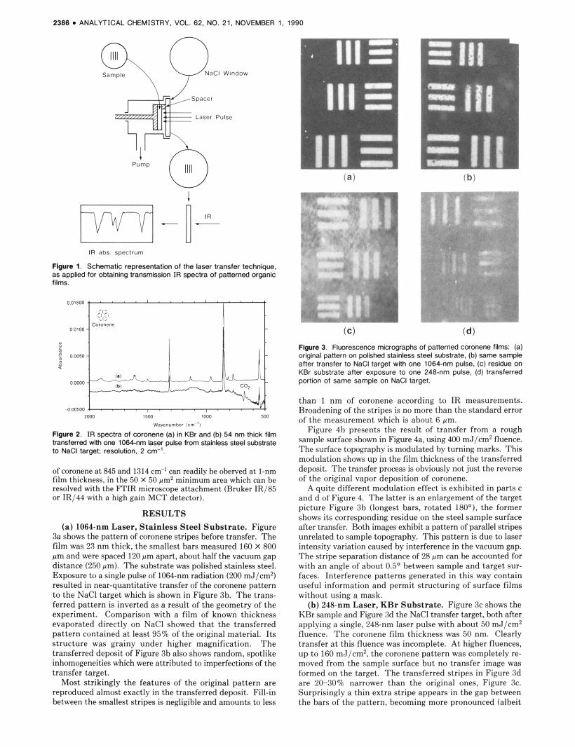
3a shows the pattern o f coronene stripes before transfer. The film was 23 nm thick, the smallest bars measured 160 X 800 pm and were spaced 120 pm apart, about half the vacuum gap distance (250 pm). The substrate was polished stainless steel. Exposure t o a single pulse of 1064-nm radiation (200 mJ/cm2) resulted in near-quantitative transfer o f the coronene pattern t o the N a C l target which is shown in Figure 3b. T h e trans- ferred pattern is inverted as a result of the geometry o f the experiment. Comparison w i th a film o f known thickness evaporated direct ly on NaCl showed tha t the transferred pattern contained a t least 95% of the original material. Its structure was grainy under higher magnification. T h e transferred deposit o f Figure 3b also shows random, spotlike inhomogeneities which were attributed to imperfections o f the transfer target.
Most str ikingly the features of the original pattern are reproduced almost exactly in the transferred deposit. Fill-in between the smallest stripes is negligible and amounts t o less
Figure 3. Fluorescence micrographs 01 panerned cwonene tllms: la) original panern on po #shed stainless steel substrate. (Dl same sample afler transfer to NaCl target with one 1064-nm pulse. IC) resaue on r(Br Subsirate aller exposure to one 248-nm pulse. Id) transferred panion 01 same sample on NaCl target
than 1 n m of coronene according t o IR measurements. Hroadening o f the stripes i s no maire than the standard error 01 the measurement u,hich is ahout 6 pm.
Figure 4h presents the result o f transfer from a rough sample surfare shown in Figwe 4a. using 400 mJ/cm2 fluence. The surfare tupographv is modulatrd hy turning marks. This modulation shows up in the film thickness o f the transferred deposit. T h e transfer prucess is obviously not just the reverse of the original vapor deposition o f wronene.
A quite different modulation effert is exhihited in parts c and d o f Figure 1. T h e la t t r r is an enlargement o f the target p i r ture Figure 3b tlungest bars, rotated lROO1. the former shows i t s rurresponding residue on the steel sample surface alter transfer. Hoth images exhibit a pattern o f parallel stripes unrelated to sample topovaphy. This pattern is due to laser intensitv \,ariation caused hv interferenre in the vacuum gap. The stripe separation distance o f 28 um can he accounted for w i th an angle o f about 0 . 5 O hetween sample and target sur- fares. Interferenre patterns generated in this way contain useful information and permit structuring of surfare films without using a mask.
(b) 218-nm Laser, K R r Substrate. Figure 3c shows the K H r sample and F i w r e 3d the NaCl transfer target. hnth after applying a single. 248-nm laser pulse wi th ahout 50 md/cm' fluence. T h e rornnene f i lm thickness was 50 nm. Clearly transfer at this fluenre was inromplete. A t higher fluences, up to 160 mJ/cm'. the coronene pattern was completely re- moved from the sample surface but no transfer image was iormed un the target. T h e transferred stripes in Figure 3d are 2U-:IO% narrower than the original ones, Figure 3c. Surprisingly a th in extra stripe appears in the gap hetween the bars o f the pattern. beroming more pronounced (albeit
ANALYTICAL CHEMISTRY. VOL. 62. NO. 21, NOVEMBER 1. 1990 2387
c r"
d
Flgure 4. Micrographs in visible light (a) and in fluorescence (b to d) of patterned coronene films: (a) 25 nm thick film panern before transfer. on stainless sleei surface corrugated by turning marks: (b) Same pattern after transfer to NaCl target with one 1064-nm pulse; (d) enlargement of the longest bars in Figure 3b. rotated 180'. ex- hibiting interference fringes: (c) corresponding residue on polished stainless steel sample.
poorly visible in the micrograph) as the bars get narrower.
DISCUSSION The 1064- and 248-nm experiments are complementary in
the sense that the substrate hut not the coronene film ah- sorbed the laser radiation in the former, while in the latter the opposite was the case. I t is obvious from Figure 3 that in both cases the deposit leaves the surface in a highly di- rectional way with an angular distribution sharply peaked at the surface normal, 0 = 0. If the transfer followed a cos2 0 distribution, as is often observed in laser desorption of small surface coverages, the pattern should be obliterated and no image formed. Instead the angular spreading is no more than about 1.4' a t 1064 nm. Apart from this directionality the results point to different mechanisms at 1064 and 248 nm.
The grainy deposit formed in 1064-nm transfers indicates that a large fraction of the film is driven across the vacuum gap in the form of solid or liquid particles. Most likely this is due to a blasting mechanism. Rapid heating of the interface between sample and film generates a rapidly expanding vapor layer which breaks up the hulk of the film and drives the fragments vertically from the surface. The process in the latter phase resembles one being used to lift contaminant particles off surfaces (3). Its high directionality, even a t film edges, as evident from Figure 3b, is astonishing.
A t 248 nm heat is deposited mainly in the top portion of the organic film, generating a dense vapor layer at the vacuum interface. Under these conditions a highly directional, adia- batic expansion of the vapor occurs (4) . We speculate that the extra stripes appearing in the transferred pattern, Figure 3d, are due to shock fronts, which are formed when the su- personic expansion plumes coming from adjacent bars of the pattern collide. A t high laser fluences, excessive heating of the expanding vapor by light absorption may be responsible for complete disappearance of a transferred pattern.
CONCLUSIONS Our results demonstrate that pulsed laser heating is a useful
method for transferring an organic surface film to a substrate on which it can he analyzed by transmission IR spectroscopy. When a moderate vacuum gap width between sample and transfer target is used, the method preserves spatial infor- mation with a precision exceeding the resolution of an IR microscope. This is especially true, and the method works best, when the substrate rather than the film itself is heated by the laser, as was the case in our 1064-nm experiments. Under these conditions particulate matter is transferred by a highly directional blasting mechanism. If the laser light is mainly absorbed by the film, directional transfer again occurs by a strongly forward-peaked expansion of the vapor. Both directional mechanisms depend on formation of a dense vapor layer and will therefore fail eventually when the surface coverage gets very small. Sample surface topography trans- lates into modulation of the transferred film thickness by effects including optical interference.
LITERATURE CITED (1) Lalare. S.: Oranier. V. Laser Chem. 1989. IO(1). 25. (2) Nelson. R. W.; Rainbow. M. J.; Lohr. D. E.: Williams. P. Science 1989,
246. 1585. (3) Imen. K.; Lee. S. J.: Allen. S. D. Conference on La$- end E k O -
Optics; 1990 Technical Osest Series; Optical Saclety 01 America: Washington. Dc. 1990 Val. 7. p 228.
(4) Kelly. R. Proc. SPIE-lnt. Soc. Opl. Eng. 1989. 1056. 258. (5) Bletsas. 1. V.; Hercub. D. M.; van Leyen, 0.; Benninghoven. A. Msc-
romokcuks 1987. 20. 407. (6) Yang. M.: Millard. J. R.: Rellly. J. P. Opt. C m m . 1985. 55. 41.
RECEIVED for review June 18,1990. Accepted August 6,1990.