Page 1
SECTION 1: GENERAL INFORMATION
Contents Page
A. Background................................................................................................................ 1.1
B. Theory of Operation...............................................................................................…. 1.3
C. Standard Run Cycle (CHN).....................................................................................…. 1.5
D. Limited Warranty......................................................................................................… 1.8
Shipping Damage.................…................................................................................…. 1.9
E. Items Supplied with the Systems…............................................................................... 1.10
F. Items to be Supplied by the Customer......................................................................…. 1.11
G. Definition of Common Terms...................................................................................… 1.12
H. Oxygen Analysis - Theory and Operation................................................................…. 1.15
I. Sulfur Analysis - Theory and Operation...................................................................….. 1.23
Page 2
INSTRUCTIONS
CHN ANALYSIS WITH THE 440 ANALYZER
SECTION 1: GENERAL INFORMATION
A. BACKGROUND
In the early sixties Dr. W. Simon of the Swiss Federal Institute of Technology patented an
instrument to automate the measurement of carbon, hydrogen and nitrogen. This patent was
acquired by Perkin-Elmer who, in 1965 introduced the 240 CHN Analyzer. In this instrument
the classical techniques of Pregl for carbon and hydrogen and Dumas for nitrogen were
combined resulting in a major advance over the labor-intensive tube weighing methods then in
common use.
Over the years many improvements were made, such as better detector filaments, a more
reliable safety circuit, a larger reduction tube, two additional valves to protect the detector while
servicing the instrument, as well as vertical scrubber and trap tubes to avoid channeling. Also,
modification kits were made available for determining oxygen as well as sulfur. Perkin-Elmer
also developed a "Carbonate Kit" which permits the differentiation of combustible carbon from
carbon present in carbonate form; as well as a kit for steel/refractory materials analysis.
The basic 240 was originally supplied with a chart recorder for reading the bridge signals in a
bar graph form. In 1969, the first major improvement in the operation of this instrument was
provided by Control Equipment who designed the MC-241 Direct Reader to automate the
tedious and error prone manual calculations.
Some years later, in a continuous effort to fully automate the 240 instrument, Control
Equipment introduced the 64 sample automation system called the MC-341 MICROJECTOR,
which was exhibited at the 1975 Pittsburgh Conference. The first system was based on a
gravity sample feed similar to the vertical sample drop used by other manufacturers. However,
collection of residue in the combustion area from previous samples often caused a reaction,
resulting in unreliable results. For this reason we replaced the vertical feed with the horizontal
64 sample automatic injector of today.
Page 1.1
Page 3
Until 1982, Control Equipment upgraded existing 240 instruments, but that year they started to
manufacture their own design, the 240-XA. On this instrument the MICROJECTOR was
replaced by a more powerful Data Handler/Controller System, consisting of the 241 Controller,
the 242 Data Terminal, and the 243 Line Printer. 1984 saw the introduction of the CEC-390
INTERFACE unit combined with the Hewlett Packard HP-150 computer as the
controller/processor for the 240-XA analyzer. The HP-150 offered many advancements and
expanded capabilities over the previous 241 CONTROLLER such as greatly expanded
software, data storage on disk, to mention but a few of the many new features.
In 1989 Control Equipment introduced the completely new Model 440 designed from the
ground up. The 440 achieves its superior performance by combining the proven techniques of
the past with the latest technology in both software and hardware. The 440 is operated by an
IBM or compatible PC computer in a sample cycle time of less than 5 minutes but it retains the
horizontal sample injection with its many advantages.
As before, the automation package is available with SAI Single Sample Automatic Injector, or
the HA-64 Fully Automatic Sample Injector with the SSI Single Sample Injection port for rush
samples.
The 240-XA and the Model 440 product line were purchased by Leeman Labs in 1990. The
products were in turn purchased from Leeman Labs by Exeter Analytical, Inc. in 1994.
ALTHOUGH THE 440 CAN EASILY BE OPERATED BY FOLLOWING THE
INSTRUCTIONS ON THE SCREEN, READ THIS MANUAL FOR INFORMATION
ABOUT HOW TO ASSURE MANY YEARS OF TOP PERFORMANCE.
ADDITIONAL SUPPORT IS ALWAYS AVAILABLE BY CONTACTING EXETER
ANALYTICAL.
IN THE USA AND WORLDWIDE IN THE UNITED KINGDOM
7 DORIS DRIVE UNIT #6A BRUNEL SCIENCE PARK
NORTH CHELMSFORD, MA 01863 BLDG #1
978-251-1411 KINSTON LANE
978-251-4536 FAX UXBRIDGE, MIDDLESEX
[email protected] UNITED KINGDOM UB8 3PQ
+ 1 895 813122 PHONE / FAX
VISIT OUR WEB SITE WWW.EXETERANALYTICAL.COM
Page 1.2
Page 4
B. THEORY OF OPERATION
In the 440 Analyzer, the carbon, hydrogen, and nitrogen content in organic and inorganic
compounds can be determined. Combustion of the weighed sample (typically 1-3 mg; in
certain cases up to 500 mg) occurs in pure oxygen under static conditions. With a conversion
kit oxygen and sulfur can be analyzed. A kit for steel and refractories is also available.
The combustion train and analytical system are shown in Figure 1. Helium is used to carry the
combustion products through the analytical system to atmosphere, as well as for purging the
instrument. Helium was selected for this purpose because it is chemically inert relative to tube
packing chemicals, and it has a very high coefficient of thermal conductivity. Argon can be
used with some 440 modifications, but is not recommended since instrument performance
deteriorates. Solenoid valves A through G control the gas flow through the system; valves H
and I are used for automatic leak testing and other maintenance purposes.
Figure –1-
The products of combustion are passed over suitable reagents in the combustion tube to assure
complete oxidation and removal of undesirable by-products such as sulfur, phosphorous, and
halogen gases. In the reduction tube, oxides of nitrogen are converted to molecular nitrogen
and residual oxygen is removed. In the mixing volume the sample gasses are thoroughly
homogenized at a precise volume, temperature and pressure. This mixture is released through
the sample volume into the thermal conductivity detector.
Page 1.3
Page 5
Between the first of three pairs of thermal conductivity cells an absorption trap removes water
from the sample gas. The differential signal read before and after the trap reflects the water
concentration and, therefore, the amount of hydrogen in the original sample. A similar
measurement is made of the signal output of a second pair of thermal conductivity cells,
between which a trap removes carbon dioxide, thus determining the carbon content. The
remaining gas now consists only of helium and nitrogen. This gas passes through a thermal
conductivity cell and the output signal is compared to a reference cell through which pure
helium flows. This gives the nitrogen concentration.
For oxygen analysis, the combustion tube is replaced by a pyrolysis tube containing platinized
carbon. The reduction tube is replaced by an oxidation tube containing copper oxide. The
sample is handled and run as before, but is now pyrolyzed in helium so that carbon monoxide is
formed from oxygen in the sample. The CO is oxidized by the copper oxide to form carbon
dioxide, which is detected and measured in the same manner as the carbon analysis. (Refer to
detailed oxygen instruction, Section l.H, page 1.14.
For sulfur analysis, the combustion tube is replaced with one containing a tungstic oxide
packing plus a dehydration reagent. The water trap is removed and replaced with silver oxide to
absorb SO2. The sample is handled and run as before, but the sulfur from the sample is
oxidized to form S02, and the water formed is removed. The S02 is detected and measured in
the same manner as the hydrogen analysis. (Refer to detailed sulfur instructions, Section l.I,
page 1.22.
Page 1.4
Page 6
C. STANDARD RUN CYCLE (CHN)
The PC Compatible Computer controls the valve sequencing of the instrument as shown in the
diagram on the front panel of the 440. To assist in maintenance and for trouble shooting it is
helpful to understand the run cycle as described below.
At the start of each run the entire system is flushed with helium at a high f low rate while the
sample is in the cool zone. With the HA automatic multi-sample injector, the injection box is
automatically purged through the P valve. The combustion train is then filled with oxygen and
the sample is injected. Shortly after sample injection, D valve closes to seal off the combustion
train from the rest of the analytical system, which is still being flushed with helium.
Combustion occurs under static conditions in an excess of oxygen at about 975° Celsius ( the
combustion temperature is user selectable ). During this time, the mixing volume is being
purged with E and F valves open. Then F closes to allow the pressure in the mixing volume to
reach atmospheric pressure.
Near the end of the combustion period, a high-heat coil around the combustion tube vaporizes
any condensates at the entrance of the combustion tube. These condensates may have been
produced by diffusion of the sample during the initial stages of combustion. To further assure
that complete combustion takes place, the ladle is retracted approximately 1 inch ( 2.5 cm ), a
small amount of oxygen is added and the ladle is again fully injected. In addition, an extended
combustion time can be selected with extra bursts of oxygen injected every 30 seconds. During
high-heat, valve E closes, A and D reopen, and the combustion products are completely flushed
from the combustion train into the mixing volume. When a pressure of 1500 mmHg (about
14.5 psig) has been reached, as monitored by the pressure transducer, valve D closes trapping
the sample gas in the mixing volume. The time required to reach this pressure is called fill time
and is recorded for diagnostic purposes. A fill time of 20-50 seconds is normal. The
combustion train remains under positive pressure until the end of the complete cycle.
While the sample gases are mixing, pure helium flows from valve C through the sample volume
and through the detectors. The signal from each detector bridge is read and stored in memory
to provide a "zero" reading (base line) with no sample gas in the detector.
When the mixing is completed F and G valves open to allow the sample gas captured in the
mixing volume to expand through the sample volume to atmosphere. During this time valve C
is closed and there is low Helium flow through the detector.
When the sample gases are near atmospheric pressure, valves F and G close and C opens. The
water, carbon dioxide, and nitrogen concentrations of the sample are measured by displacing
the sample gas through the detectors to atmosphere. The volume of sample gas in the system is
large enough so that the helium flow used allows measurement of the contents of each detector
in sequence, under steady state conditions. The sample gas passes through the detectors at a
constant flow, pressure, and temperature to eliminate any variations in water vapor pressure or
water vapor concentration due to changes in water adsorption on the walls of the pneumatic
system.
Page 7
Carbon, Hydrogen and Nitrogen output signals are recorded while the sample gas flows through
the detectors. The difference in microvolts between each "read" signal and the "zero" level
recorded earlier for the same detector is in direct proportion to the concentration of the sample
gas measured.
At the end of the cycle, the exhaust valves are opened to allow the sample gases to escape to the
atmosphere. The Computer then prints out the calculated results, puts the instrument into
standby with C valve open, and awaits the next command. With the HA automatic injector the
results are printed after completion of each run.
CHN Analysis Supply Kit Parts List
When ordering this kit, specify whether it is for the Manual / SAI or HA automation. The CHN
Kit P/N is 125-00021 (for Manual / SAI), or P/N 125-00012 (for HA).
Description EAI PART #
Silver Gauze, 12x100mm 0240-0092B
Silver Oxide/Silver Tungstate 25 gms 0240-0113
Ascarite 500 gms 0240-0115
Effluent filters Pkg 10 0240-0137A
Silver Vanadate 25 gms 0240-1117C
Quartz Wool 28 gms 0240-1118
Magnesium Perchlorate 500 gms 0240-1119
Acetanilide 2 gms 0240-1121
Platinum gauze 45 mesh 0240-1147B
Trap tube, small diam, 8 inch 0240-1217
Scrubber tube, large diam. 8 inch 0240-1217B
Micro-spatula 0240-1286
Spring for normally closed valve assembly 0240-1291
Plunger for normally closed valve assembly 0240-1292
O-ring for normally closed valve assembly 0240-1293
Silver tungstate / Magnesium oxide 25 gms 0240-1344C
Copper wire, cuprin, 1 lb. 0240-1362
Reduction tube, large diam. 0240-1573
O-ring mixing volume 0240-1581
O-ring entrance plug 0240-1582
O-ring viton 7/16 id x 1/8w 0240-1583
Mechanical Assembly Manifold Valve Tool 120-00038
Maintenance Kit, Valve Manifold 125-00005
Fuse AGC 2A/250V 213-1002
Page 1.6
Page 8
Description EAI PART #
Fuse AGC 3A/250V 213-1003
Gasket, Capsule Receiver 304-00007
O-ring Grease, Krytox, 2 oz. 306-00001
Leak Detector fluid (SNOOP) 306-00016
Ball Teflon 3/8 inch diameter 307-00025
Wrench, tube nut 313-00011
O-ring Buna 5 ½ inch ID x 3/32 316-00003
O-ring Viton 3/16 inch ID x 1/16 316-00008
Brush, capsule duster 318-00003
Tweezers dumont style 318-00005
Connector, glass 318-00009
Tin capsule, smooth, 2.9 x 6 mm, Pkg 1000 6703-0418
Sleeve, nickel, 7x5mm, Pkg 1000 6703-0499
Ladle Sha multi-sample 6703-0503
Combustion tube, CHN, SHA 6703-0514
Page 1.7
Page 9
D. LIMITED WARRANTY
The following standard equipment warranty applies to this system:
ONE YEAR on parts and labor, F.O.B. North Chelmsford, MA except for the Computer and
Printer where manufacturer's warranty applies. Extended on site warranty is available at an
extra charge.
Excluded from the Exeter Analytical, Inc. warranty are any operating supplies, such as
combustion and reduction tubes; traps, scrubbers, sample ladles, and mixing volume; reagents
and consumables including platinum boats; furnaces, hi-heat coils, thermocouples, and elastic
seals (O-rings and gaskets).
This warranty does not cover loss, damage, or defects resulting from transportation to the
buyer's facility, improper or inadequate maintenance by the buyer, buyer supplied software or
interfacing, unauthorized modification or misuse, use of operating supplies or parts other than
those sold or authorized by Exeter Analytical, Inc. operation outside of environmental
specifications for the equipment, or improper site preparation.
NOTE: See section l.D, page 1.8, for instructions regarding shipping damage.
Page 1.8
Page 10
SHIPPING DAMAGE
WE HAVE DONE OUR VERY BEST IN THE MANUFACTURE AND PACKING OF THIS
MATERIAL. THE TRANSPORTATION CARRIER IN ACCEPTING IT FOR DELIVERY
TO YOU IS RESPONSIBLE FOR DELIVERING IT IN ITS ORIGINAL CONDITION.
If the shipment is not delivered in good condition and in accordance with the quantity listed on
the Bill of Landing or the Packing List, you must have the shortage and/or damage noted by the
Carrier on both the delivery receipt and freight bill, or by a special form provided by the Post
Office, UPS, FedEx etc.
Effective July 1, 1972 the Interstate Commerce Commission has ruled that Transportation
Companies will not have to honor any losses or damage claims unless notation is made on the
freight bill at the time of delivery. It is the buyer's responsibility to make a complete inspection
immediately upon receipt of purchased goods.
If bundles or crates are in apparent good order, but upon opening contents are found to be
damaged, call the Carrier for their adjuster to inspect the damage and have the Transportation
Company / UPS / Post Office / FedEx mark the freight bill or packing list indicating that the
shipment was received with concealed damage.
Make your claim immediately since the Transportation Company / UPS / Post Office / FedEx
have a time limit for presentation of claims.
Exeter Analytical, Inc. is willing to assist in every possible manner in collection claims for loss
or damage, but this willingness on our part does not make us responsible for filing or collecting
claims or replacing material. Claims for loss or damage may not be deducted from our invoice,
nor payment of the invoice withheld awaiting adjustment of such claims.
IMPORTANT - DO NOT RETURN GOODS WITHOUT A RETURN MATERIAL
AUTHORIZATION NUMBER (RMA #). CALL EXETER
ANALYTICAL FOR DETAILS.
Return of special or non-stock items cannot be authorized. Credit for goods returned - under
authorization - will depend on value to us based on our selling price, less any charge covering
expenses for shipping, handling, inspection, refinishing, etc., providing that the material is
received in good condition with transportation charges prepaid. Any Credit rendered must be
used against future purchases.
Page 1.9
Page 11
E. ITEMS SUPPLIED WITH THE SYSTEM
The following is as standard equipment with the 440 instrument:-
Part No. Description Quantity
------------- ------------------------------- ---------
2000-0018 440 Instruction Manual 1
NOTE: For items supplied with the computer package, see separate packing list for the IBM PC
or compatible computer and the CEC-490 Interface unit.
NOTE: For the initial operation, a corresponding supply kit is recommended.
Page 1.10
Page 12
F. ITEMS TO BE SUPPLIED BY THE CUSTOMER
The following material must be available at time of installation:
a. Gases
Helium, 99.995 mole percent minimum. Size 1A cylinder with C.G.A. connection No. 580.
Oxygen, 99.995 mole percent minimum. Size 1A cylinder (or next size smaller) with C.G.A.
connection No. 540.
b. Regulators (Can be purchased from Exeter Analytical, Inc.)
Helium - Two stage with stainless steel diaphragm, 5-60 psig outlet pressure (EAI P/N 240-
0085-A)
Oxygen - Two stage with stainless steel diaphragm, 5-60 psig outlet pressure (EAI P/N 240-
0084-A)
GC grade clean 1/8” copper tubing of sufficient length to connect the regulators to the 440
instrument. If the regulators are purchased from Exeter Analytical, copper tubing is included.
c. Balance
Accurate sample weighing is essential. A microbalance such as the Cahn Model 31 with
automatic tare and RS-232 output is recommended since this model can be interfaced to the 440
for automatic weight entry. A resolution of at least one microgram in the 2-20 microgram range
is required. CAHN balances are available from Exeter Analytical, Inc.
d. Miscellaneous
Sample handling accessories, such as desiccators, forceps, brushes, spatulas, etc. Ladle
and tube racks. Calibration standards. Fresh reagents are also required. A complete set
of
handling accessories and reagents can be purchased in kit form from Exeter Analytical,
Inc. Such "startup kits" contain everything needed to analyze 1000 samples.
Page 1.11
Page 13
G. DEFINITION OF COMMON TERMS
ACETANILIDE Used as a standard or conditioner in the analyzer for calibration
purposes. It has known percentages of C, H, and N.
BB VALVE The valve controlling oxygen flow for the HA automation. Located on the top
left side of the six valve manifold.
BENZOIC ACID Used as a standard. Also to check nitrogen blanks.
BLANKS Blank value = blank read minus blank zero. An indicator of the stability of the
system.
BOAT Platinum container used to inject the sample into combustion furnace.
BRIDGE Electrical configuration of the thermal conductivity filaments.
CAPSULE Aluminum, tin, or silver container. Used for sealing samples with an accurate
weight. Maintains sample integrity prior to combustion.
COMBUSTION TIME Time for sample to fully combust in oxygen environment.
COMBUSTION TUBE Quartz tube used for packing reagents and for sample
combustion.
CYCLOHEXANONE Used as a standard.
CYSTINE Used as a standard.
DETECTOR The heart of the analyzer consisting of three bridges. Determines the
percentages of carbon, hydrogen, and nitrogen in the sample via thermal conductivity.
DETECTOR OVEN Keeps the temperature of the detector, pressure transducer, mixing
volume, and sample volume constant.
DOUBLE DROP On HA automation, two samples can be dropped for one run. Used for
samples with low concentrations of CHN. Sample ID requires a + prefix.
Page 14
Page 1.12
FILL TIME Time required to build up the pressure in the mixing volume to 1500 mmHg.
FURNACE Heats the reduction and combustion tubes to operating temperatures.
HEATED LINE Connects the reduction tube outlet to the inlet of the mixing volume.
Heated to prevent condensation of gases on tube walls.
INJECT SOLENOID Solenoid used only on the HA injector to actuate the rotation of the
sample wheel.
INJECTION Moving the ladle, containing a boat or capsule with the sample into the
combustion furnace.
INJECTOR BOX For the HA automation, the box assembly that houses the sample wheel.
K-FACTOR Instrument sensitivity factor in microvolts per microgram, calibrated using a
chemical standard. Also known as "gain".
LADLE Transports the boat or capsule with the sample into the combustion furnace.
LONG BURN Extended combustion time. Adjustable for hard to burn samples.
MIXING VOLUME Spherical bottle in which sample gases are mixed and become
homogenous.
MOTHER BOARD The main printed circuit board. All 440 power supplies are located here.
PRESSURE TRANSDUCER Used to check for leaks in the system and to monitor pressure in
the mixing volume.
P-VALVE The valve on the injector box of the HA used to automatically purge.
PROFILE Generated by the bridge signal. Used to determine if a leak or malfunction
occurs in the system. See Section 9.C for examples of diagnostic profiles.
READ SIGNAL Steady state signal produced by the detector when sample gases are
present in stable concentration.
Page 1.12
REDUCTION TUBE Quartz tube packed with reduced copper. Removes excess oxygen from
the sample gas and reduces oxides of nitrogen to free nitrogen.
RUN One sample analysis from start to finish, including printout.
RUN CYCLE Typically a day of operation - the entire analytical sequence of
runs from the first run to the last run.
Page 15
SAMPLE VOLUME Tube where sample gas is exhausted from the mixing volume prior to
entering the detector.
SCRUBBERS Removes water and C02 from the gas supplies.
SENSITIVITY See K-factors.
SLEEVE Nickel - to maintain integrity of the sample capsule and to protect the quartz
ware from devitrification.
SOLENOID VALVE Used to control gas flow throughout the instrument.
TRAPS Used for removing water and C02 from the sample gas.
ZERO VALUE Bridge signal with only pure helium flowing through the detector.
Page 1.14
Page 16
H. OXYGEN ANALYSIS
1. General Theory
With the Oxygen Analysis Kit, oxygen in organic compounds can be determined with the CE-
440 Elemental Analyzer. It is assumed that the user is familiar with the general operation of the
instrument (See sections 3 and 4).
In the oxygen mode, the sample is pyrolyzed at 1080 °C in a helium environment using
platinized carbon to convert oxygen and oxygen cracked products to carbon monoxide. The
carbon monoxide and other gases then pass through free copper at approximately 900 °C where
sulfur compounds are retained, and through an external U-tube packed with Ascarite where any
acid gases are removed. The carbon monoxide and remaining gases then pass through copper
oxide at approximately 670 °C where the carbon monoxide is converted to carbon dioxide.
Any basic gases are removed by the standard water trap. Carbon dioxide is absorbed by
Ascarite placed in a tube between the two sides of the carbon thermal conductivity detector.
The readout from the C detector is used for the Oxygen calculations. Hydrogen and Nitrogen
are also calculated but the results are not usable. The nitrogen blank can be used to indicate
leaks.
NOTE:
Accurate Oxygen analysis is limited to compounds, which do not contain fluorine,
phosphorous, silicon, or most metals. The presence of such interferences could either poison
the catalyst, thereby shortening the lifetime of the pyrolysis tube, or oxidize, thus removing
oxygen from the sample. Exceptions are metal cations, which can be handled although
problems often occur.
2. Modifications for Oxygen Analysis
The following changes are made on the analyzer for the determination of oxygen:
A carrier tee has to be added to the helium inlet line to so that helium flows through the oxygen
line used for CHN analysis. This stabilizes the capsule blank value to 250 +/- 10 microvolts,
lending very good accuracy to low level oxygen determinations. It also allows for H2O doping
when a H2O doping tube is substituted for the O2 scrubber.
In the Parameter Table the Purge Time should be set to 50 seconds and the Combustion Time
set to 40 seconds.
Page 1.15
Page 17
The CHN combustion and reduction tubes are replaced with tubes packed with reagents suitable
for oxygen determination. An acid-gas scrubber U-tube is placed between the combustion and
reduction tubes to remove any acid gases which would otherwise pass through the detector and
result in a high signal.
Sample injection is delayed so that no pyrolysis products diffuse into the cool zone.
3. Oxygen Analysis Supply Kit Parts List
When ordering this kit, specify whether it is for the Manual / SAI or HA automation. The
Oxygen Kit P/N is 125-00022 (for Manual / SAI), or P/N 125-00023 (for HA).
Description …. Manual system EAI
PART #
Oxygen Pyrolysis Tube - Manual 0240-1962
(must be used with 240-1963, oxidation tube)
Oxidation Tube - Large Diameter 0240-1963
Acid-gas scrubber U-tube 0240-1356
Ladle, w/ Cutout 0240-1321A
U-tube Retention Bracket 0240-1964
Oxygen Analysis Connector (Kit of 2) 0240-0136
Tube Nut, 4 0240-1032
Tube Washer, 4 0240-1042
U-Tube shield 6703-0605
Silver capsules, 100 6703-0419
0-Rings (4) 0240-1583
Platinum Gauze, 9.5 x 145 mm, 45 mesh 0240-1147B
Copper Oxide Wire, (Cuprox), 454 gms 0240-1092
Platinized Carbon, 10 gms. 0240-0119A
Benzoic Acid, 4 gms 0240-1120
The following standard CHN supplies are not included in the oxygen kit:
Quartz wool 0240-1118
Ascarite 0240-0115
Copper wire, Cuprin 0240-1362
Silver Gauze 0240-0092B
Magnesium Perchlorate 0240-1119
Page 18
4. Packing Tubes
Packing of tubes is defined under "Tube Replacement" in the Service Menu of the 440 program.
Use clean tubes, quartz wool, etc. as for CHN. See section 7.D.
Page 1.16
a. Pyrolysis Tube
Roll the platinum gauze so that it will fit snugly into the pyrolysis tube and slide one up against
the indentations (short end). Add a small wad of quartz wool.
Add 2 inches ( 5 cm ) of platinized carbon. Gently tap the tube to prevent the reagent from
channeling. As an option slide a second platinum plug up against the platinized carbon and add
another 2 inches ( 5 cm ) of platinized carbon. Gently tap the tube again and add a small wad of
quartz wool.
Add 0.5 inch ( 1.2 cm ) of copper wire (Cuprin) and pack it with a wad of quartz wool.
Roll up a piece of silver gauze so that it will fit snugly into the tube. Clean as for CHN and
slide it up against the copper wire. There should be about 0.5 inch ( 1.2 cm ) of empty space
left in the tube.
Page 19
Page 1.17
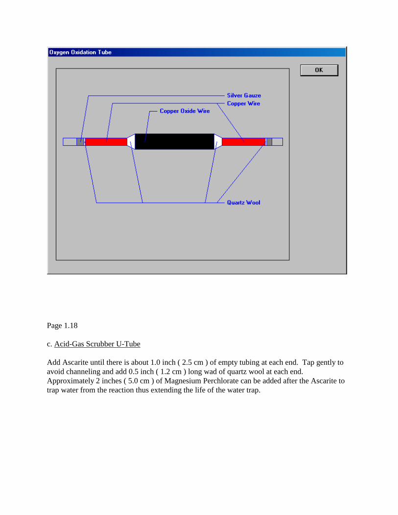
b. Oxidation Tube
Roll up two pieces of silver gauze and clean. Insert one into the tube leaving about 1.0 inch
( 2.5 cm ) of empty space. Add a small wad of quartz wool from the inside and fill up the rest
of the small diameter of the tube with copper wire (Cuprin). Tap gently to avoid channeling
and pack it with a small wad of quartz wool.
Fill the large diameter of the tube with copper oxide wire (Cuprox), tap gently and add a small
wad of quartz wool.
Fill the other small diameter of the tube with copper wire (Cuprin) as above, add a wad of
quartz wool and the second roll of silver gauze. About 1.0 inch ( 2.5 cm ) of the tube should
remain empty.
Page 20
Page 1.18
c. Acid-Gas Scrubber U-Tube
Add Ascarite until there is about 1.0 inch ( 2.5 cm ) of empty tubing at each end. Tap gently to
avoid channeling and add 0.5 inch ( 1.2 cm ) long wad of quartz wool at each end.
Approximately 2 inches ( 5.0 cm ) of Magnesium Perchlorate can be added after the Ascarite to
trap water from the reaction thus extending the life of the water trap.
Page 21
d. Oxygen and He Scrubbers, Carbon Dioxide and Water Traps
Pack as for CHN mode of operation. See Section 7.D.
Page 1.19
5. Installation of Kit
The 440 should be in a powered up state. However the furnace should be cooled to less than
100° Celsius before installing the pyrolysis and oxidation tubes.
Go to the Service Menu - Tube Replacement mode for oxygen analysis (see Section 7.D).
Select Pyrolysis and Oxidation tube replacement, and follow directions to remove the tubes.
Page 22
Insert the Oxygen Pyrolysis tube into the combustion furnace and the Oxidation tube into the
reduction furnace. Allow the system to purge for approximately ten minutes before raising the
furnace temperatures. After purging, install the acid-gas scrubber U-tube instead of the end
connector. Use the bracket supplied with the kit to support the U-tube assembly.
Replace trap tubes if necessary.
WARNING: The Platinized Carbon will combust if hot and exposed to air or oxygen.
6. Initial Adjustments and Settings
Use the leak test mode to check for any leaks.
Set the pyrolysis (combustion) furnace temperature to 1080°C and the oxidation (reduction)
furnace temperature to 670°C.
If a new pyrolysis tube is being used the reagents need to be carbonized (conditioned). This
will take approximately 5 runs of an unweighed high carbon content material such as
anthracene or a paraffin oil. Then 5 runs of an oxygen bearing compound should be run, such
as Acetanilide. During these runs adjust the fill time to 40 +/- 10 seconds. Once the ladle and
the pyrolysis tube are carbonized, run 5-10 empty blanks to equilibrate the system. When the
oxygen blanks agree within +/-10 microvolts and are less than 300 microvolts, the instrument is
ready for operation. If not, continue running blanks.
NOTE: High carbon compounds (low oxygen) should be run with weights below 3000
micrograms.
7. General Operation
See the instructions under Analytical Run Menu in section 4.B, page 4.12.
In the oxygen-mode sample injection is delayed. If the 64 Sample Automation is used, the ladle
is injected 1.0 inch ( 2.5 cm ) less than in the CHN mode. These changes are incorporated into
the oxygen program for both single sample and multi-sample operation. All other modes
remain the same as for CHN.
Page 1.20
8. Calibration Procedure
For both the Single Sample and the 64 Sample Automation, the following general rules apply:
Acetanilide (P/N 0240-1121) in silver capsules is recommended as a calibration standard.
Aluminum capsules can be used for economic reasons however they tend to oxidize, thus
causing low results. Do not expect specified accuracies when using aluminum capsules.
Page 23
Run 4-6 empty blanks until the blank is stable to +/- 10 microvolts. Once the system is
stable, run two conditioners, an analytical blank, a conditioner and then two standards. Store
the conditioned blank value and the averaged K's obtained from the standard runs.
K-factor for Oxygen
An average K-factor for oxygen should range from 14-19 mmV/mmg. The KO should be
approximately 75% of the KC while in the CHN mode. The hydrocarbon blanks should range
from 300 to 500 mmV and be weight independent. The maximum spread of the K's values over
the course of a day should not exceed 0.30 mmV/mmg.
For increased accuracy, establish a KO factor using a standard material closely approximating
the composition, weight, and molecular structure of the sample to be analyzed.
If the instrument has not been used for more than one hour, run an unweighed conditioner prior
to any calibration or sample determination.
9. Replacing Tubes
Use the automatic leak test mode to establish that the instrument is free of leaks after changing
any tubes. Use the Tube Replacement mode in the Service Menu (see section 7.D) to change
the tubes.
Pyrolysis tube
The pyrolysis tube should last a very long time unless the catalyst has been poisoned. However,
when it is necessary to change the tube, the furnace could be turned off the night before the
pyrolysis tube is to be changed to save time. This will allow plenty of time for the tube to come
down below 100°C. In general the acid-gas scrubber U-tube and the oxidation tube should be
replaced when the pyrolysis tube is changed.
Always replace the pyrolysis tube when the calibration factor is not reproducible, or if the KO
climbs to as high as 33 mmV/mmg.
Page 1.21
Acid-gas scrubber tube
Replace the U-tube whenever the pyrolysis tube is changed, or when the Ascarite changes from
light brown to white.
10. Trouble Shooting
Page 24
Symptom: Inaccurate Results.
Caused by copper reagent containing copper oxide. Carbon monoxide formed in the pyrolysis
tube is oxidized by the copper to form C02 which is absorbed in the U-Tube.
Correction:
Make 5 or 10 conditioning runs to reduce the copper oxide.
Symptom: Variable results.
Caused by platinized carbon becoming "poisoned" when running samples containing metals,
phosphorous, fluorine, or silicon.
Correction:
Change the platinized reagent in the pyrolysis tube.
Symptom: Erratic results.
Caused by carbon buildup on the ladle.
Correction:
Lightly burn some of the excess carbon off the ladle. Make sure to leave some carbon on the
ladle or the capsule will stick and the ladle will need re-conditioning.
Page 1.22
Page 25
I. SULFUR ANALYSIS
1. General Theory
With the Sulfur Analysis Kit, sulfur in organic or inorganic compounds can be determined with
the Model CE-440 Elemental Analyzer. It is assumed that the user is familiar with the
operation of this instrument.
In the sulfur mode, the sample is combusted at approximately 1020 °C in an oxygen
environment using tungstic oxide as a catalyst. The combustion products consisting of sulfur
dioxide and other gases then pass through Magnesium Perchlorate, 8-Hydroxyquinoline and
free copper heated to approximately 820-840°C where interferences such as water, halogens,
and oxygen are removed. Sulfur Dioxide is absorbed by silver oxide placed in a tube between
the two sides of the hydrogen thermal conductivity detector and heated to 180-190°C. The
read-out from the H detector is used for the sulfur calculations. Carbon and Nitrogen are also
calculated.
2. Modifications for Sulfur Analysis
The following changes are made on the Analyzer for the detection of sulfur:
The CHN combustion and reduction tubes are replaced with tubes packed with reagents suitable
for sulfur determination.
A halogen-gas scrubber U-tube is placed between the combustion and reduction tubes to
remove halogens which would otherwise pass through the detector and result in a high signal.
A heated sulfur dioxide absorber tube replaces the water trap.
3. Warning
Magnesium Perchlorate is used for removing water in the combustion tube, and in the halogen-
gas scrubber U-tube when performing sulfur determinations. Since Magnesium Perchlorate is
an oxidizing agent, it can react with organic vapor (non-combusted products). A 3 mg sample is
the largest organic sample which can safely be used on an explosive hazard could develop. If
the sample material is partially inert, the total organic content must not exceed 3 mg. When the
Magnesium Perchlorate in the halogen-gas scrubber becomes yellow, it must be replaced.
When installing the combustion tube, make certain that the Magnesium Perchlorate does not
extend into the combustion furnace section.
Page 1.23
Page 26
Alternatively, 10 to 20 mesh calcium chloride can be used as a dehydrating agent. However,
since it is not as effective in removing water, the precision will decrease. Water might break
through and cause drifting in the sulfur signal. No explosive hazard exist when using calcium
chloride, regardless of the amount of organic sample present.
4. Sulfur Analysis Kit Parts List
Description … Manual system PART No.
Sulfur Combustion Tube 0240-1369 (Manual system)
Sulfur Reduction Tube - Large furnace 0240-1961
Halogen-gas scrubber U-tube 0240-1371
Sulfur Dioxide absorber tube 0240-1372
Heated Assembly for absorber tube 0240-0652A
U-tube retention bracket 0240-1374
Sulfur analysis connector kit (2 supplied) 0240-0136
Platinum Sample Boat, 200 mg 0240-0090
O-Ring (4) 0240-1583
Tube Nut 0240-1032
Tube Nut washer 0240-1042
Cuprin wire (copper), 454 gms 0240-1362
8-Hydroxyquinoline, 100 gms 0240-0133
Silver Oxide, 25 gms 0240-0132C
S-Benzylthiuronium chloride, 10 gms 0240-1338
Tungstic Anhydride (Tungstic Oxide), 25 gms 650-00046
Tungstic Oxide, Powdered, 50 gms 650-00046P
U-Tube Sheild 6703-0605
Quartz Chips, 30 gms 650-00060
Sea Washed Inert Sand, 50 gms 650-00061
The following standard CHN supplies are not included in the sulfur kit:
Quartz wool 240-1118
Magnesium Perchlorate 240-1119
5. Preconditioning of Reagents
The reagents supplied with-the kit have been preconditioned at Exeter Analytical, Inc.
However, it is good policy to condition older reagents. This should be done prior to S change
over.
Silver Oxide - heat 100 grams at 150°C for 48 hours in a muffle furnace, cool and store in a
desiccator.
Tungstic Oxide - heat 100 grams at 900°C for one hour in a muffle furnace, cool and store in a
desiccator.
Copper (Cuprin) - loosely pack 200 grams in a large bore quartz tube. Heat for 2 hours at
400°C while purging with helium. Cool and store in a desiccator.
Page 1.24
Page 27
6. Packing Tubes
Packing of tubes is defined under "Tube Replacement" in the Service Menu section of the
Software package (see section 7.D). Clean tubes, quartz wool, etc. as for CHN (section 7.D).
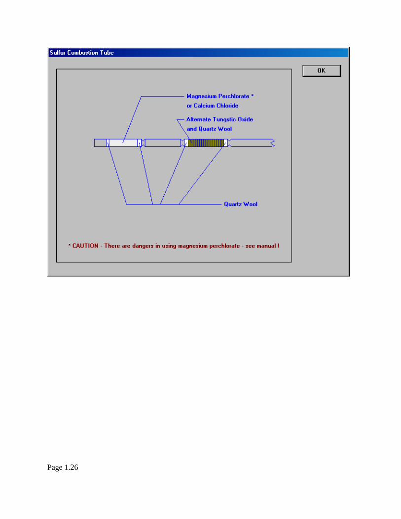
a. Sulfur Combustion Tube
Hold the tube vertically with the short end to indentations down. Using a packing rod, insert 10
mm of quartz through the entrance (long) end of the tube and pack it firmly against the second
set of indentations.
Add 30 mm of tungstic oxide. Gently tap the tube to prevent the reagent from channeling.
Pack in the tungstic oxide firmly with 10 mm of quartz wool to fill the space up to the first set
of indentations.
Turn tube around. Leave the space between the second and third set of indentations empty.
Pack 10 mm of quartz wool against the third set of indentations.
Add 30 mm of Magnesium Perchlorate through the exit end of the tube. Make sure that the
quartz wool is firmly placed so that Magnesium Perchlorate cannot accidentally move into the
heated zone of the combustion tube. Gently tap the tube to prevent the reagent from
channeling.
Pack the magnesium Perchlorate in firmly with 10 mm of quartz wool.
Page 1.25
Page 29
b. Sulfur Reduction Tube
Hold the tube vertically with the short end to indentations down. Insert 10 mm of quartz wool
through the long end and pack firmly against the indentation.
Add 16 cm of copper wire (Cuprin) and pack loosely. Place 10 mm of quartz wool against the
copper. Leave the remaining portion empty.
To reduce heat loss, pack a wad of quartz wool between the ceramic core and small diameter of
the reduction tube at each end of the furnace. When using the small diameter tube (240-1370),
place an additional wad of quartz wool under the middle of the tube in the furnace as a support.
Page 1.27
Page 30
c. Sulfur Dioxide Absorption Tube
Hold the tube vertically with the short end to indentations down. Insert 10 mm of quartz wool
through the long end and pack firmly against the indentations.
Add 10 mm of silver oxide. Gently tap the tube while adding the silver oxide to prevent
channeling. Pack in the silver oxide firmly with 10 mm of quartz wool.
Page 1.28
Page 31
d. Halogen Gas Scrubber U-Tube
Pack 10 mm of quartz wool against the indentation through the long end.
Fill the tube to just shy of the centerline with Magnesium Perchlorate. Tap the tube gently while
filling to prevent channeling. Add 10 mm of quartz wool.
Under a chemical exhaust hood, mix 1/3 of inert sand to 2/3 of 8-hydroxyquinoline, which
prevents the reagent from clogging when absorbing halogens. Fill the tube to within 37 mm of
the open end with this mixture. Tap the tube gently while filling to prevent channeling. Add
10 mm of quartz wool. Leave the remaining end of the tube empty.
Caution: Do not inhale the vapor or dust of 8-Hydroxyquinoline.
Page 1.29
Page 32
e. Scrubber Tubes and C02 Trap
Pack as for CHN mode of operation (see section 7.D).
7. Installation of Kit
Go to Service Menu - Tube Replacement mode for Sulfur analysis. Go to replacement of both
tubes and remove the combustion and reduction tubes following the screen instructions. Insert
the sulfur combustion tube into the combustion furnace, making certain that the Magnesium
Perchlorate section does not extend into the furnace area.
Insert the sulfur reduction tube with the indentation towards the exit, i.e. to the right facing the
instrument. Check that the filter in the effluent fitting assembly is clean. Replace if necessary.
After purging, install the halogen-gas scrubber U-tube instead of the end connector. Make sure
that the indented side of the U-tube is connected to the reduction tube. Use the bracket supplied
with the kit to support the U-tube assembly.
Next, go to changing of the sulfur dioxide trap. Remove the water trap and slide the heated
jacket over the sulfur dioxide absorption tube and install in place of the water trap. Make sure
that the indented end is towards the top. Install a new effluent filter at the gas exhaust end. Plug
the supplied Temperature Controller into a suitable power source. The Controller is factory set
to 185°C. Please verify the setpoint is set between 180°C – 190°C. Adjust if necessary. Refer to
the Temperature Controller manual supplied with the kit.
8. Initial Adjustments and Settings
Use the leak test mode to check for any leaks. Set the combustion furnace temperature to 975
+/- 25°C, and the reduction furnace temperature to 820 +/- 20°C.
Run 5 to 10 blank runs to condition the reagents and to equilibrate the instrument. During these
runs adjust Fill Time to 40-60 seconds. Leave O2 pressure at about 20-25 psig as in CHN
mode. If the C and S blanks are stable and less than 300 mmV, the instrument is ready for
operation. If not, run another set of blanks.
Page 1.30
Page 33
9. Calibration
Blanks
Run 4-5 unweighed conditioners. Use a 1-3 mg sample of acetanilide which has zero sulfur
concentration to establish the blank for sulfur. Always run a conditioner before and after a
blank. Several blanks following each other will decrease in value since the instrument has a
"memory" effect, which is compensated for by using the blank value in the calculation. The S
blanks vary from instrument to instrument but should be from 300 to 1000 mmV +/- 50 mmV.
A normal blank run is used to establish the C and N blanks which should approximate those
used for CHN analysis.
K-factors
S-Benzylthiuronium chloride or phenylthiourea are used for establishing sulfur calibration or K-
factors. Run 5-6 weighed 1-3 mg samples and use the average for the KS factor or use the
automatic K's and B's option.
For increased accuracy, establish a KS factor using a standard material closely approximating
the composition, weight, and molecular structure of the sample to be analyzed.
10. General Operation
See the instructions under the Analytical Run Menu in section 4.C, page 4.13. If the instrument
has not been used for more than one hour, run an unweighed conditioner prior to any calibration
or sample determination.
Use a sample weight of 1-3 mg. Always add 10 mg of tungstic oxide to the boat or capsule,
then weigh a 1-3 mg sample and add an additional 70 mg of tungstic oxide. If a capsule is used,
shake the mixture after weighing and crimping.
For volatile samples, use aluminum capsules.
DO NOT USE TIN CAPSULES AT ANY TIME IN THE SULFUR MODE.
11. Replacing Tubes
a. Reduction tube
Replace the reduction tube after about 100 runs, using the Tube Replacement mode. 200 runs
for HA. See section 7.D for information on changing reduction tubes.
Page 1.31
Page 34
b. Combustion tube
If the tungstic oxide reagent is channeled or separated, re-pack the tube using the original
reagent. After 100 runs, or if the Magnesium Perchlorate appears caked or shows signs of
containing excess moisture, replace the reagent. Always replace the combustion tube when the
calibration factor is not reproducible. Use the Tube Replacement mode, under the Sulfur Tube
menu.
c. Halogen-gas scrubber tube
Replace the U-tube when the 8-hydroxyquinoline changes from light brown (tan) to yellow or
when the Magnesium Perchlorate becomes yellow. Use the Tube Replacement mode.
d. Sulfur Dioxide Absorber tube
Replace when the color of the reagent changes from dark brown to light tan over the length of
the tube. Use the Tube Replacement mode.
Use the automatic leak test mode to establish that the instrument is free of leaks after changing
any tubes.
Page 1.32