15
www.ziegler-instruments.com 1 | 15 © Ziegler Instruments Order No. -E1.R0-921023-2014-EN RM 12 ... 16 User Manual RM12 ... 16 Analogue Digital Multimeter (User Manual)
www.ziegler-instruments.com 1 | 15
©Z
iegl
erIn
stru
men
tsO
rder
No.
-E1
.R0
-92
10
23
-20
14
-EN
RM
12
...
16
Use
rM
anu
al
RM12 ... 16Analogue Digital Multimeter (User Manual)
Analogue Meters With Moving - Iron Movement

ON
(1)
(2)
(3)
(4)
(5)
(6)
V
DC AC
20 16.
V �
1000 V 300 mA 10 A
fused
1000 V max
(7)
100 20 30
ON
OFF
�TRMS
MAN MAX
DATA
MIN MAX/
AUTO
MAN
FmA0
CA
F
---
�
HzV
---
V~
V---
mA---
0C
---A
(8) (9) (10) (11)
(12)
(16) (15) (14) (13)
(18)
(17)
(19)
VA
MIN MAX DC ACON
- . . .8 8 8 8100 20 30
MAN DATA
KW MW
kHz %
0C ��nF
��
++5
(1) Liquid crystal display(2) ON OFF pushbutton/(3) Pushbutton for data hold
and MIN MAX storage functions/
(4) Pushbutton for manual rangeselection
(5) Multi function pushbutton
(6) Function selector switch.
(7) Terminal sockets with automaticblocking system.
(8) Symbol for CONTINUOUSLY ON’’ "
(9) Display for digits decimal point and,polarity.
(10) Display for manual range selection,DATA hold and MIN/MAX storage.
(11) Display for the selected function(12) Display for the unit of
measured quantity.(13) Over range indication for
positive analog range.(14) Pointer for analog indication.(15) Scale for analog indication(16) Over range indication for
negative analog range.(17) Low battery indication.(18) Buzzer indication(19) Display 0C for temperature
measurement range.
www.ziegler-instruments.com 2 | 15

www.ziegler-instruments.com 3 | 15
1. Introduction:Thank you very much for selecting this Multimeter.This handheld multimeters are suitable for use in the fields ofgeneral electronics and electrical engineering.These multimeters are manufactured as per DIN43751
2. Safety features and safety precautionsYou have chosen a multimeter which provides you a very high degree ofsafety The analog digital multimeters RM. - 12 ...16 aremanufactured and tested in compliance with the safety standard DINVDE and IEC DIN EN VDE In case of0411 /1010-1 /61010-1 .0411-1incorrect use or careless handling the safety of both user and multimeter,is not assuredFor proper use and safe handling it is absolutely necessary to read and,understand the operating instructions before using the meter.For your safety and for protection of the multimeter the RM,12...16 multimeters are fitted with an Automatic terminal BlockingSystem (ABS).It is coupled with the function selector switch whichblocks the terminal sockets not necessary for measurement.
Please note the following safety precautions:The multimeter must be operated only by persons who understandthe danger of shock hazards and are aware of the necessary safetyprecautions Shock hazards exist wherever voltages of more than.30V (TRMS) are present.Do not work alone in shock hazardous environment while carryingout measurement.The maximum permissible voltage between any of the terminalsockets and ground is V But voltages of more than V(7) 1000 . 500must be applied only to the unblocked sockets on the voltagemeasuring ranges (function selector switch set to a V position )(6) ’’ ’’Take into account that unexpected voltages can occur on deviceunder test (e g defective instrument)For example capacitors may. . ,be charged to a dangerously high voltage.Verify that the test leads are in good condition e g no cracked, . .insulation no open circuits in the leads or connectors, .This multimeter must not be used for measurements on circuits withcorona discharge (high voltage).Be particularly careful when measuring on HF circuits Dangerous.composite voltages may exist there.Measurements under moist environmental conditions are notpermitted.All current measuring ranges with the exception of the A range of, 16
13, are protected with fuse. The maximum permissibleRMvoltage of the measuring circuit (=nominal voltage of the fuse)is500V ~on the mA ranges" " , 600V ~ on the "A" ranges.You must use the multimeter only in power systems when the" " ,current circuit is protected by a fuse or a circuit breaker of A and20 ,when the nominal voltage of the system does not exceed V500 .For safe voltage measurements in power systems upto V we1000 ,recommend the KS measuring adapter which is available as an30 ,accessory Its internal resistance limits the measuring current in the.case of overvoltage in correct operation and safely suppresses,sparking from spark gap Also refer to Section Voltage. 8.1"measurement on electrical systems up to V with KS1000 30measuring adapter.
Repair replacement of parts, :When opening the meter live parts may be exposed Therefore the, . ,meter must be disconnected from the measuring circuit prior to openingits case for repair or replacement of parts If repair cannot be avoided.unless the meter is opened and live this work must only be performed,by a qualified person who understands the danger involved.
Faults and abnormal stress:When it is realised that the safe operation is no longer possible take the,meter out of service and secure it against accidental use.Safe operation may not be possible,
when the meter shows obvious signs of damage,when the meter no longer functions correctly,after prolonged storage under adverse conditions,due to severe stress during transportation.
3. Switching the multimeter ON" "
BatteryWe have already fitted your meter with a V flat cell battery according to9IEC F or IEC LR It is ready for operation6 22 6 .61 . Before you use themeter for the first time or after storage refer to Section Maintenance, 18.1" -Battery."
Switching the meter ON" "Press the ON OFF pushbutton" / " .(2)Switch ON is acknowledged by a sound signal As long as you"- " .keep the pushbutton pressed all segments of the liquid crystal display,(LCD) will appear The LCD is shown on page. .1After the pushbutton is released the meter is ready for operation, .
Note:Electric discharges and high frequency influence may cause incorrect-information to be displayed and block the measuring process Reset the.meter by switching it OFF and ON again otherwise check the battery,connections.
Meaning of the symbols on the device
Warning of a danger point(Attention refer to the user,manual)
Earth (ground) terminal.
Double or reinforced insulation

www.ziegler-instruments.com 4 | 15
Disconnect the meter from the measuring circuit before you open it and,see section Maintenance.18" !"
Automatic TURN OFF-The meter turns off automatically when the measured value remains,constant var) iations of the measured v alue > 2 + ( 10digits for aboutminutes and when neither a pushbutton nor the function selector switchis operated during that time It remains ON however when a current. , ,measuring range is selected and a measured value digits is displayed30< .
How to prevent automatic TURN OFF-In order to prevent automatic TURN OFF select CONTINUOUSLY" " "ON mode For this press y" . , ellow multi function pushbutton and the- (5)" / " (2) . " "ON OFF pushbutton together The function CONTINUOUSLY ONis shown on the LCD by the symbol(1) .(8)
Turning the multimeter OFFPress the ON OFF pushbutton" / " .(2)
4. Function and range selectionThe function selector switch is coupled with the Automatic terminal(6)Blocking System ABS which allows access only to two correct sockets) (for each function Prior to switching to the mA or A functions or from. " " " "the mA or A functions remove the test lead from the corresponding" " " " ,socket When the test leads are plugged in the terminal blocking systems. - ,prevents accidental switching to nonpermissible functions.
4.1 Switching the DC current measuring ranges ON " "3 mA for RM123 mA and 3 A for RM 13300 mA mA and A for RM30 , 3 14...16
The current measuring ranges mentioned above are not automaticallyselected when the meter in switched ON When you need these.measuring ranges for your measurements you must additionally activate,them.
set the function selector switch to(6) " "(yellow symbol)Briefly press the yellow multi function pushbutton- .(5)The multimeter acknowledges the start of an offset calibration forthese DC current measuring ranges with a sound signal The digital.display of the multimeter shows CAL during the calibration(9) " "procedure.Wait for CAL to disappear from the display" " .Thereafter the above current measuring ranges are switched ON, " ."They remain switched ON until the multimeter turns OFF-automatically or is switched OFF manually.Note:Automatic turn OFF is inactive on all current measuring ranges when-the measured value display exceeds digits30 .Set the function selector switch to the desired position(6) .
4.2 A utorangingThe multimeters feature autoranging for all measuring ranges with theexception of the mV30 300 ,mV and A10 ~ranges Autoranging.is automatically selected after switching the multimeter ON According.to the measured quantity applied the multimeter automatically selects,the measuring range which gives the best resolution When switching to.frequency measurement and to ratio measurement the previously,selected voltage measuring range is maintained.
ON
The meter switches automatically to:the next higher range at + 3099 1 +( digits digit)the next lower range at + 240/280 1 -( digits digit)from the 300mA to the 3mA range at + 24 1 -( digits digit)
provided the m300 A mA and A ranges are not selected according30 , 3to section4.14.3 Manual range sectionYou can switch OFF autoranging and select the ranges manuallyaccording to the table on the following page.Manual mode is switched OFF when pushbutton AUTO MAN is pressed/(4) 1 , (6) ,for approximately s when the function selector switch is operatedor when the meter is turned OFF and ON again.When switching back to autoranging from mV30 or mV300 ranges,3 V range is automatically selected.
1) When these measuring ranges are selected2) except for RM 12/133) except for RM 14...16
5. Liquid crystal display
5.1Digital displayThe digital display shows the measured value with correct location of decimal(9)point and sign The selected measuring Unit and the function. (12) (11)are simultaneously displayed When measuring DC quantities a minus sign. ,appears in front of the digits when the positive pole of the measured,quantity is applied to the" "input terminal When upper range limit. 3099(on the r ange 1999: , " " .) is exceeded then OL is displayedWith V A, and W measurements, the digital display is updated two timesper second.5.2 Analog indicationThe analog indication with pointer presentation gives the dynamicresponse of a moving coil movement and is updated times per second- 20 ,when measuring V A and W, .Analog indication is of particular advantagewhen observing variations of measured values and for calibrationprocedures.The analog indicator has its own polarity indication When measuring.DC quantities the analog scale has a negative range of scale, (15) 5

www.ziegler-instruments.com 5 | 15
divisions so that variations of the measured values around zero can be" "observed exactly When the measured value exceeds the range of.indication the left triangle is shown before the polarity of the analog, (16)indicator switches over after approximately s The over range indication0.7 .on the measuring range ( digits on the range3099< , 1999<) is shownby the right triangle.(13)
6. ’’ ’’DATA hold facilityThe DATA function allows to automatically hold the measured values.This is particularly useful for instance when connecting the probes to, ,the measuring point requires full attention When the measured value is.applied and the condition according to the table shown below is met’’ ’’ ,the meter holds the measured value on the digital display and emits asound signal The probes can now be removed from the measuring point.and the measured value on the digital display can be read When the(9) .measured value falls below the limit specified in the table the meter is,reactivated for a new storage.The analog indication is not influenced by the DATA hold ,The actualmeasured value can still be noted read Note that with a held digital/ .display the location of the decimal point is also held With autoranging, .selected the measuring range of the analog indicator is no longer known, .
1) Reactivated by falling below the specified limits of the measured value.2) With the exception of the ranges mV and mV30 300 .3) 240/280 digits when the ranges 3 mA for RM 12/13 and 300 m A30 ,
mA A for RM3 , 14...16 are selected according to section4.1.As long as the DATA hold function is active manual range selection is,not possible The DATA hold function is switched OFF when. , ,
The DATA pushb" ” utton (3) is pressed for approx s This is1 . .acknowledged by sound signals2 .The function selector switch is operated or(6)The multimeter is turned OFF and ON again.
7. Minimum value and Maximum value MIN MAX storage facility’’ / " .With the MIN MAX function you can hold the minimum and the maximum/ ,measured value which was applied to the input of the multimeter afteractivating MIN MAX function The most important application is the/ .determination of the minimum and the maximum value for long term-monitoring of measured quantities MIN MAX does not influence the. /analog indication The actual measured value can still be noted read/ .Apply the measured quantity to the meter and select the measuringrange prior to activating the MIN MAX function/ .With the function activated you can select the measuring ranges only,manually if you switch to another range the stored MIN MAX values are, , /cleared.
FunctionDATA
Activate
Store
Reactive1)
Reset
Short
Long
DATAMIN MAX/
(3)
Condition
MeasuringRanges
280<24<3)
>OL280<280 >24 >3)
OL280 >
dis-played
storedmea-suredvalue
Cleared
flashes
dis-played
flashes
Cleared
1 x
1 x
2 x
MeteracknowledgementDisplay
DATASoundSignal
Meas.Valuedigital
Limit ofMeasured
Values(digits)
V 2)
A�
F Hz, %,
V 2)
A�
F Hz, % ,
The MIN MAX function is switched OFF when the MIN MAX pushbutton/ , /(3) 1 ,is pressed for approximately s or when the function selector switch(6) , .is operated or when the meter is turned OFF and ON again
Notes:The mV30 and mV300 measuring ranges can only be selectedmanually with the AUTO MAN pushbutton’’ / ’’ ! (4)On the V r1000 ange an intermittent sound signal warns you when the, ,measured value exceeds the upper range limit.
Caution:Ensure current measuring range ( mA or A ) is not selected’’ ’’ ’’ ’’ for voltagemeasurement When the cut out rating of the fuses is exceeded because! -of incorrect operation a dangerous situation exists, .!
Zero adjustment on the mV30 measuring rangeConnect the test leads to the meter and join the free ends.
After having selected the measuring range briefly press the yellow multi, -function pushbutton.(5)The meter acknowledges zero setting by a sound signal the LCD shows,’’00.00’’ 1 + .( digit)and the decimal point flashes The displayed voltageat the instant the pushbutton is pressed is used as reference value,(max 200 +digits)it is automatically deducted from the values measuredthereafter.
The zero adjustment is cleared when;By pressing the yellow multifunctionpushbutton for a long time(5) ,clearance is acknowledged by the two sound signal.By switching the instrument OFF.
8. Voltage measurementAccording to the voltage to be measured set the function selector,
switch to V(6) ,~ V or V .Connect the test leads as shown The. ’’ ’’socket should beconnected to the lowest potential ground available.
FunctionMIN MAX/
2 x Short,30 mV/300 mVand 0C
1 x short
short
short
Short
Long
DATAMIN MAX/
(3)
MeasuredValues
MINandMAX
Stored
Storage Continuedin the background,new MIN MAX/ .
values are displayed
Same as,.1Stored Values are
not cleared
Cleared
actualmeas-uredvaluestoredMIN
valuestoredMAXvalue
sameas.1
Cleared
MINand
MAXflash
MIN
MAX
sameas.1
Cleared
MeteracknowledgementDisplay
MINMAX
Meas-uring
rangesSoundSignal
1.Activate and
Store
2.Store and
display
3.Return to.1
Reset
1 x
1 x
1 x
1 x
2 x
Meas.Valuedigital
VA
�F Hz, % ,
0C
VA
�F Hz, %,
0C
Sameas.1

www.ziegler-instruments.com 6 | 15
Voltagemeasurement
Voltagemeasurementonelectricalsystemsupto V1000withtheKS measuringadapter30
22 98.
~/(-)+
~/(+)-
~/+
~/-
22 98.
8.1Voltage measurement on electrical systems up to1000V with the KS30 measuring adapter.
On low Voltage systems transient overvoltages of several kilovolts can- ,occur due to switching functions or lightning discharges Direct connection.of your multimeter to such systems for voltage measurement can bedangerous.For voltage measurements in power systems with nominal voltages upto1000V, use the KS30 measuring adapter. It is an adapter for multimeterwhich eliminates dangers caused by overvoltages and incorrect operationof the multimeter It provides the following protective functions. ..
Protection of the input circuit of voltage measuring range ofmultimeters The internal resistance of the KS limits the current in. 30the case of overvoltage.Overload capacity contin: uously Vrms1200
Transient (rise m10 s fall m/ 1000 s) kV max6 .Safe suppression of sparking from spark plug after overvoltage.Current limitation in the case of incorrect operation (e g applying a. .voltage to a current input)
Voltages above V can be measured with a high voltage probe1000 - ,provided the necessary safety precautions are taken!
9. Current MeasurementFirst disconnect the power supply to the circuit being measured and/or to the load and discharge all capacitors within that circuit, .Select the DC current measuring ranges as described in section4.1With the function selector switch select A,(6) for currents mA300< ,and mA for currents mA When measuring current of unknown300> .magnitude , select the highest measuring rangefirst.Select the function corresponding to the measured quantity by brieflypressing the yellow multi function pushbutton Each time the- .(5)pushbutton is pressed alternate switching takes place between DC,and AC on the RM 12...15 or between DC and (DC + AC)on the RM 16. The change-over is acknowledged by a soundsignal The symbols DC and AC are displayed as per selected. (11)function on the LCD.When selecting a range with the function selector switch the DC,(6)function is always set by default When pressing the yellow multi. -function pushbutton for a long time the multimeter always switches(5) ,back to DC and acknowledges this by two sound signals.Connect the multimeter in series with the load as shown Ensure, .that the connections are tight (without contact resistance).
Notes on Current measurement:The multimeter must be used only in the power systems where the,current circuit is protected by a fuse or a circuit breaker of A and20 ,when the nominal voltage of the system does not exceed V500 .Make the measuring circuit connections mechanically strong andsecure so that they do not accidentally open The conductor cross.sections and connection points should be designed to avoid excessiveheating.On the mA and A ranges ( A range for RM300 10 16 13), anintermittent sound signal warns you when the measured value,exceeds the upper range limit.The current measuring ranges upto mA are protected to a short300

www.ziegler-instruments.com 7 | 15
Currentmeasurement
ACcurrentmeasurementwith clip on currenttransformers) - (
2 105.
~
~
A(9.1.1)
mA(9.1.1)
V(9.1.2)
~/(-)+
~/(+)-
2 105.
300...mA
mA
~/(-)+
~/(+)-
10 00.
10...A
A
circuit current of A by a fuse A V in conjuction with power25 1.6 500/ ,diodes The cut out capacity of the fuse is kA at a rated voltage of. - 20500V~ and ohmic load.The A and A current measuring ranges are protected by a A3 10 16 /600V fuse. The cut-out capacity of the fuse is 100 kA at a normalvoltage of V600 ~and ohmic load.
Caution:The measuring ranges A and A of RM3 16 13 are not protectedby a fuse!
A blown fuse is signalled on the LCD the instant a measured quantityhaving a voltage of more than V is applied to the corresponding4connection sockets Then the digital display shows the word. , (9)" "FUSEAfter a fuse has blown eliminate the cause of the overload before,using the meter again!Replacement of the fuses is described in section Maintenance.18 ’’ .’’
9.1AC current measurement with (clip-on) current transformer
9.1.1 Transformer output mA A/
Caution:If current transformers are operated with an open circuit on the secondaryside e g due to defective or disconnected leads a blown fuse in the, . . ,meter or a wrong connection dangerously high voltages can occur at, ,the connectors Therefore verify that the current circuit of the multimeter. ,and secondary winding of transformer connected to the multimeterforman intact circuit Connect the transformer to the sockets. and mAand or A/ .The maximum permissible operating voltage is the nominal voltage ofthe current transformer When reading the measured value take into. ,account the transformer ratio and the additional error in indication.
Transformer output RM 12The RM 12 shows the switching position ’’ A and the’’corresponding sockets Connect to this socket a clip on current. ) - (transformer with a transmission ratio of then the measured values;1000:1are displayed directly in the A range’’ ’’ .
9.1.2 T ransformer output VMany transformers have voltage output (refered as mV A)/The secondary output must therefore be connected to the connectionsockets and V.
10. Resistance measurementVerify that the device under test is electrically dead External voltages.would falsify the measured result!Set the function selector switch to(6) " �."Connect the device under test as shown.

www.ziegler-instruments.com 8 | 15
DiodeTestForwarddirection Reversedirection
Resistancemeasurement
0600
- + - +
ContinuityTest
0000
- + - +
2 105.
- +
Zero adjustment on the30 � measuring rangeWhen measuring small resistance values on the 30 � range, you caneliminate the resistance of the leads and contact resistance by zeroadjustment.
Connect the test leads to the multimeter and join the free ends.Briefly press the yellow multi function pushbutton The meter- .(5)acknowledges zero adjustment by a sound signal the LCD shows,"00.00" 1+ .( digit) and the decimal point flashes The resistance measuredat the instant the pushbutton is pressed is used as reference value(max digits) It is automatically deducted from the values measured200.thereafter Zero adjustment can be cleared. .By pressing the yellow multifunction pushbutton for a long time and(5)is acknowledges by two sound signals.By switching the multimeter OFF.
11. Diode test and continuity testVerify that the device under test is electrically dead External voltages.would falsify the measured results!Set the function selector switch to(6) " "connect the device under test as shown.
Forward direction and or short circuit/ :The multimeter displays the forward vol tage in Volts As. long as the voltagedrop does not exceed the maximum display value of V you can also1.999 ,rest several series connected elements or reference diodes with small-reference voltage.Reverse direction or open circuit:The multimeter indicates overrange OL" "
Note:Resistors and semiconductor junction in parallel with the diode falsify themeasured results!
Diode test and continuity test with buzzerWith the buzzer function selected the meter emits a continuous sound" " ,signal on the range approx V...0 1 . .To switch the buzzer ON:
Briefly press the yellow multi function pushbutton- .(5)The multimeter acknowledges turn ON with a sound signal At the same- .
time , the symbol (18) .appears on the LCD
To switch the buzzer OFFBriefly press the yellow multi function pushbutton again- (5) .
The multimeter acknowledges turn-OFF with a sound signal. The
symbol (18) .disappears from the LCDWhen selecting the function Diode test and continuity test with the function" ’’selector switch the buzzer is always switched OFF Repeated brief,(6) .pressing of the multifunction pushbutton alternately switches the buzzer(5)on and off When pressing the push button for a long time the buzzer is. ,always switched OFF this is acknowledged by the buzzer,sounding twice.
www.ziegler-instruments.com 9 | 15
12.Capacitance measurement RM 15 and 16Verify that the device under test is electrically dead External voltages.would falsify the measured results!Set the function selector switch to F(6) " "Connect the (discharged ) device under test to the! " " ’’ ’’and Fsockets via test lead.
Notes:Connect polarised capacitors with the pole to the" " " " .socketResistors and semiconductor junctions in parallel with the capacitor falsifythe measured results!
Zero adjustment on the nF measuring range30When measuring small capacitance values on the nF range the30 ,internal resistance of the multimeter and the capacitance of the leadscan be eliminated by zero adjustment.
Connect the test leads to the meter without device under test.Briefly press the yellow multi function pushbutton- .(5)The meter acknowledges zero adjustment by a sound signal by,displaying ( digit) on the LCD and by a flashing decimal""00.00" 1+point The capacitance measured at the instant the pushbutton is.pressed is used as reference value (max digits) It is automatically200. .deduced from the values measured thereafter.
The zero adjustment can be clearedBy pressing the yellow multi function pushbutton for a long time- (5) ,clearance is acknowledged by the two sound signal.By switching the multimeter off.
13. Frequency measurement ( RM 15 and 16)Frequency measurement is possible on all voltage measuring ranges inAC DC and (AC DC) modes, + .
Set the function selector s witch to V(6 ~ ,V or VConnections are made the same way as for voltage measurement,See foot note on page(8) .21Briefly press the yellow multi function pushbutton- (5)The multimeter switches to frequency measurement The frequency.is displayed on the LCD.
See section Specifications for the lowest measurable.17" "frequencies and the maximum permissible voltages.
Changing over between voltage frequency and duty cycle,measurement
Repeated brief pressing of the yellow multi function switch changes- (5)the measuring functions in the following order:Voltage frequency duty cycle voltage ....
From frequency or duty cycle measurement directly switching back,to voltage measurement is possible.by pressing the yellow multi function pushbutton for a long time- (5) .The meter acknowledges this by two sound signals The voltage.measuring range last selected is maintained.by operating the function selector switch.(6)
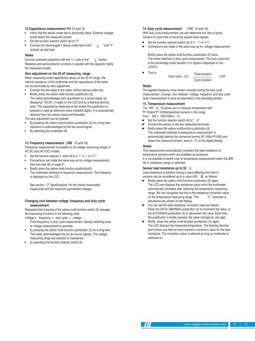
14. Duty cycle measurement ( 15 and 16)RMWith duty cycle measurement we can determine the ratio of pulse,duration to cycle time of recurring square wave signals- .
Set the function selector switch to V(6) or VConnections are made in the same way as for voltage measurement
Briefly press the yellow multi function pushbutton twice- (5) .The meter switches to duty cycle measurement The duty cycle that. -is the percentage pulse duration of a signal is displayed on the-LCDin%
That is: Pulse durationDuty cycle = (%) x100
Cycle duration
Notes:The applied frequency must remain constant during the duty cyclemeasurement Change over between voltage frequency and duty cycle. - ,factor measurement is done as described in the preceding section.
15. Temperature measurementThe RM 12...16 allows you to measure temperature withPt and Pt temperature sensors in the range100 1000from� 200 (� 100)0C850+...0C.
Set the function selector switch to(6) " �"Connect the sensor to the two unblocked terminals.Briefly press the yellow multifunction pushbutton.(5)The multimeter switches to temperature measurement it,automatically detects the connected sensor (Pt to Pt ) and100 1000shows the measured temper ature in 0C on the digital display.
Notes:This measurement automatically considers the lead resistance oftemperature sensors which are available as accessory.It is not possible to switch over to temperature measurement when the 30W
Sensor lead resistance up to 50 �
Lead resistance of sensors having a value differing from that of��
Briefly press the yellow multi function pushbutton again- (5) .The LCD now displays the resistance value which the multimeterautomatically considers after selecting the temperature measuringrange We can recognise that this is the resistance correction value.on the temperature measuring range The. ’’ 0C character is’’simultaneously shown on the display.You can set the lead resistance correction value as follows:Press the DATA MIN MAX pushbutton to increment the value or-- / (3) ,the AUTO MAN pushbutton to decrement the value Each time/ (4) .the pushbutton is briefly pressed the value changes by one digit, .Briefly press the yellow multi function pushbutton again- (5) .The LCD displays the measured temperature The flashing decimal.point shows you that we have entered a correction value for the leadresistance The correction value is retained as long as multimeter is.switched on.
sensors can be considered up to a value of50 as follows:

www.ziegler-instruments.com 10 | 15
Each time the yellow multi function pushbutton is briefly pressed- (5) ,the display changes between measured temperature and correctionvalue of the lead resistance.
We can exit the temperature measurement functionby pressing the yellow multi function switch longer this is- (5) ,confirmed by the two sound signals.by changing the function selector switch.
Note:For the lead resistance the actual value measured on the digital,multimeter should be taken as correction value and not any specifiedvalue.
16. Computer interface via RS 232CThe RM multimeters are fitted with a serial RS C interface232-for transmission of measured data to computer The measured values.are optically transmitted through the case with infrared light to an interfaceadapter which is attached to the multimeter The measured data is passed.to the computer via a cable.
Switching the interface ONWhen switching on the multimeter press the ON OFF pushbutton, " / "(2) " -- / " (3) .and the DATA MIN MAX pushbutton together
With interface switched ON automatic turn OFF of the meter is, -inactive .This is shown on the LCD by(1) flashing of the (8) symbol.The DATA function cannot be activated’’ " .
Interface packs as accessories
Interface adapter with memory:By using this adapter it is possible to store the measured data withoutinterfacing the multimeter to the computer This stored data can be.transferred later on to a computer For establishing a powerful multimeter.system you can connect upto ten multimeters offline Online connection.upto six multimeters to the computer is possible via memory adapter.
The interface packs include the adapters the necessary connection,cables and the com data acquisition and evaluation software" " 100with operating instructions.
com software100The com100 software package corsists of a WINDOWS version.
With com you can simultaneously access store display,100 , ,and document the measured data of several RM multimeters.
The measured values are presented:As digital display and analog indication similar to that of themultimeter (up to multimeters). 4In traces (XY and Yt)as on a channel recorder-4 .In tabular form (data logger upto channels): 10 .
The measured data is stored in ASCll format for further processing.For the use of com the following requirements must be met,100 :
ON
Software:
MS WINDOWS or higher3.0 .
Hardware:IBM compatible PC with MB main memory for1 the WINDOWS version.A VGA or EGA monitor.A hard disk with MB free storage space2 .A disk drive for disks with MB storage capacity" 3.5 1.44 .A MICROSOFT compatible mouse-If you wish to make hardcopya printer supported by WINDOWS.

www.ziegler-instruments.com 11 | 15
Instrinsic error of digital display+ %... ... + .( of rdg digits) at reference conditions
Overloadcapacity(3
12 13 14 15 16Overload
ValueOverloadduration
0.5 + 3 4) 0.5 + 34)
0.5 + 3 0.5 + 30.25 + 1 0.1 + 10.25 + 1 0.1 + 10.25 + 1 0.1 + 10.35 + 1 0.1 + 10.75 + 2
( Digit)300 ...10 0.75 + 30.75 + 1 ( Digit)10 <
( Digit)300 <
Contin-uously
- - - -0.75 + 3
( Digit)10 <
- - 1.0 + 5 (> 10 Digit)1.0 + 5(>10 D) 1.0 + 20.25 + 2 - 1.0 + 5(>10 Digit)
1.0 + 2
- 1.0 + 5 (> 10 Digit)- 1.0 + 2- - 1.5 + 2(>10 Digit)
1.5 + 2(>10 Digit) - -
1.5 + 2(>10 Digit)- 1.5 + 2(>10 Digit)
1.5 + 2 - - -10<) (Digit - - -
- - - -
0.36 A 5)
0.36 A 5)
6) 6)
6) 6)
0.36 A 5)
0.5 + 3 4)
0.5 + 30.4 + 10.4 + 10.4 + 1
0.6 + 12.0 + 1
0.25 + 1
0.5 + 5 (> 10 D)
0.5 + 20.5 + 5 (> 10 D)
0.5 + 21.0 +5 (> 10 D)
1.0 + 2---
---
1.5 + 4 (> 10 D)
1.5 + 4 ( > 10 D)1.75 + 4(>10D)
0.4 + 34)
0.4 + 3
0.2 + 1
0.2 + 1
0.2 + 10.4 + 12.0 + 10.1 + 1
5) Continuously
6) RM 13 (Without 16 A fuse!) : 16 A continuously, 20 A 5 minRM 14 ... 16: 12 A 5 min, 16 A 30 s
1200 V
DC
ACeff rms/
sinewave
12A 5min
500 V
DC10 min
ACeff rms/
sinewave
- - - -- - - -- - - -
- - - -- - - -
17.Specifications
Reso-lution Input impedance
12 13 14 15 16
V
V~
A~
3.000 V
30.00 V
300.0 V1000 V
300.0 ��
3.000 mA30.00 mA
300.0 mA
3.000 A10.00 A
3.000 mA30.00 mA
300.0 mA10.00 A
30.00 A2)
300.0 A2)
3.000 mA300.0 mA
10.00 A
30.00 �
300.0 �
3.000 kW30.00 kW300.0 kW
3.000 MW30.00 MW
2.000 V
1)
1)1)
1)
16A
16A
1)
1)
1)
1 mV
10 mV
100 mV1 V
100 nA1 mA
10 mA100 mA1 mA
10 mA
1 mA10 mA
100 mA10 mA
10 mA100 mA
1 mA
100 mA10 mA
10 m�
100 m�
1 �
10 �
100 �
1 k�
10 k�
1 mV
1) TRMS measurement2) Display with (clip on)current transformers- 1 : 10003) At0 0 ... + 40 0C4) With zero adjustment without zero adjustment digits, 35 +
11 M�����40 pF10 M�����40 pF10 M�����40 pF10 M�����40 pF11 M�����40 pF
10 M�����40 pF
10 M�����40 pF10 M�����40 pF
Voltage drop approx.
12 S 13 S14 S /
15S/16 S
- - 15 mv15 mV 15 mv 150 mV150 mv 150 mv 650 mV1V 1 V 1V- 100 mV 100 mV- 300 mV 270 mV- - 150 mV150 mV 150 mV -1 V 1V 1 V- 300 mV 270 mV150 mV - -1V - -- - 150 mV
- - 270 mV
No load voltagemax .3.2 Vmax .3.2 V
max .1.25 V
max .1.25 Vmax .1.25 Vmax .1.25 Vmax .1.25 Vmax .3.2 V
Meas-urementFunction
Measuring Range
�
A
A~
V
A
10 <G�����40 pF30.00 mV 10 mV
10 <G�����40 pF300.0 mV 100 mV
11 M�����40 pF3.000 V 1 mV
10 M�����40 pF30.00 V 10 mV
10 M�����40 pF300.0 V 100 mV
10 M�����40 pF1000 V 1 V
3.000 V 1) 1mV30.00 V 1) 10mV300.0 V 1) 100 mV1000 V 1) 1V
- 1V
RM

www.ziegler-instruments.com 12 | 15
3) At 0C 40 + ... 0C4) With zero adjustment without zero adjustment digits; 50 + .
Meas-urement
Func-tion
F
Hz
%
Measuring Range
RM12 13 14 15 16
ResolutionDischargeResistance
U0 max
0.1 Hz1 Hz10 Hz
100 Hz
0.1 %
0.1 0C
0.1 0C
0.1 0C
0.1 0C
1 Hz1 Hz
10 Hz
100 Hz
1 Hz
-
-
-
-
45 Hz45 Hz
45 Hz
100 Hz
-
-
-
-
-
pt100
0C
pt1000
fmin V ~
300.0 Hz3.000 kHz30.00 kHz100.0 kHz
2.0...98.0%
...200.0-200.0 +0C
...200.0 +850.0 +0C...100.0 -200.0 +0C
...200.0 +850.0 +0C
fmin V
10 pF 250 k � 2.5 V30.00 nF
100 pF 250 k � 2.5 V300.0 nF
1 nF 25 k � 2.5 V3.000 ��
10 nF 25 k � 2.5 V30.00 ��
Intrinsic error of digital display+ %... ... + .( of reading digits) at reference conditions
OverloadCapacity 3)
Overloadduration
Overloadvalue12 13 14 15 16
����� ����� ����� 1.0 + 34)
����� ����� ����� 1.0 + 3����� ����� ����� 1.0 + 3����� ����� ����� 3.0 + 3
����� ����� �����
����� ����� �����
����� ����� �����
����� ����� �����
����� ����� �����
0.5 + 17)
1Hz... 1 kHz 5 +Digit8)
1kHz ...10 kHz; + 5 Digit/kHz8)
2 Kelvin + 5 Digit9)
1.0 + 59)
2 Kelvin + 2 Digit9)
1.0 + 29)
500 VDC AC/eff rms/
sine10 min
3> ;kHz1200 V30> ;kHz300V
100>kHz30 V
500 V
DC
ACeff rms/
sine
continu-ously
10 min
7) Range 3 V : U E = 1.5 V eff rms/ ... 100 V eff rms/
30 V : UE = 15 V eff rms/ ... 300 V eff rms/
300V : U E = 150 V eff rms/ ... 1000 V eff rms/
8) On the range V3 , - 15 ... 5 ,square wave signal positive on one side Vf const not Hz or integral multiple= ,. 163.84 .
9) Without sensor.
www.ziegler-instruments.com 13 | 15
Reference conditions
Ambient temperature:23 +0C 2 +K
Relative humidity:45% ... 55 % RH
Frequency of measuredquantity
45Hz ...65 HzWaveform of the measuredquantity
sinusoidal
Battery voltage8 V 0.1 +V
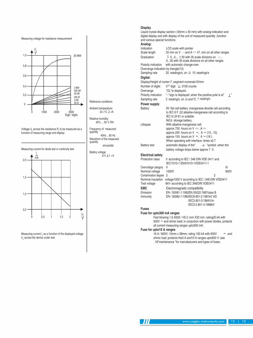
Measuring voltage for resistance measurement
Voltage Ux
across the resistance Rx
to be measured as afunction of measuring range and display.
Measuring current Ix
as a function of the displayed voltageU
xacross the device under test
1,0
0,8
0,6
0,4
0,2
0
0 1000 2000 3000Digit digits/
Ux
V30 MW
3 MW300 kW30 kW300 W3 kW30 W
2,0
1,5
1,0
0,5
0 0,5 1 1,5 2
Ix
mA
Ux
V
Measuring current for diode test or continuity test
DisplayLiquid crystal display section ( mm x mm) with analog indication and65 30digital display and with display of the unit of measured quantity function,and various special functions.Analog:Indication LCD scale with pointerScale length 55 mm on V and A 47 ,mm on all other rangesGraduation 5...0... 30 with 35 scale divisions on ,
0...30 with 30 scale divisions on all other rangesPolarity indication with automatic change over-Overrange indication by triangle(13)Sampling rate 20 readings s on/ , �� 10 ; /readings sDigital:Display Height of numer segment numerals mm/ -7 . 15/Number of digits 33/4 digit 3100 countsOverrange " " .OL is displayedPolarity indication " �" , "sign is displayed when the positive pole is at "Sampling rate 2 reading s on/ , ��and 0C :1 reading/s
Power supplyBattery 9V flat cell battery manganese dioxide cell according; -
to IEC F alkaline manganese cell according to6 ,22 -IEC LR or suitable6 61NiCd storage battery.
Lifespan With alkaline manganese cell- :approx hours on V750 . ,Aapprox hours on V200 . ~, A ~ (12...15)approx hours on V150 . ~, A ~ (16 )When operating with interface times x: 0.7
Battery test automatic display of the" " ,symbol when thebattery voltage drops below approx V7 . .
Electrical safetyProtection class II according to IEC DIN VDE and/ 348 0411
IEC EN VDE/1010-1 /61010-1 0411-1Overvoltage category II IIINominal voltage 1000V 600VContamination degree 2 2Nominal insulation voltage V according to IEC DIN VDE1000 / 348 0411Test voltage 6kV~according to IEC 348/DIN VDE0411EMC Electromagnetic compatibilityEmission EN EN class B/ 50081-1:1992 55022:1987Immunity EN IEC kV AD/ 50082-1:1992 8 801-2:1991
/ 3 801-3:1984 /IEC V m/ 0.5 801-4:1988IEC kV
FusesFuse for upto mA ranges300
Fast blowing A V mm X mm rating kA with1.6 500 / 6.3 ; 32 ; 20500V ~ and ohmic load; in conjuction with power diodes, protectsall current measuring ranges upto mA300 .
Fuse for upto A ranges1016 A / 600V; 10mm x 38mm; rating 100 kA with 600V ~ andohmic load protects the A and A ranges upto V see; 3 10 600 ;.18" " .maintenance for manufacturers and types of fuses

www.ziegler-instruments.com 14 | 15
Influencequantity RangeofInfluence
Measuredquantity/
Measuring range
Variation 1)
+ %... ... + .( of rdg digits)
12 ...14 15 16
Temperature
Frequencyof the
measuredquantity
0 0C21 +0Cand
25 + 0C 40 + ...0C
15 Hz ... < 30 Hz30 Hz... < 45 Hz65 < 400 ...Hz Hz400 < 1 ...Hz kHz1 < 20 ...kHz kHz15 Hz... < 30 Hz30 Hz.. < 45 Hz65 < 1 ...Hz kHz15 Hz... < 30 Hz30 Hz ... < 45 Hz65 < 1 ...Hz kHz
Crest. 1... 3factor CF 5...3 <
30/300 mV 1.0 + 3 1.0 + 1
3... 300 V 0.15 + 1 0.1 + 1
1000 V 0.2 + 1 0.1 + 1V ~ 0.4 + 2 0.3 + 2
300 �A2) ... 0.5 + 1 0.15 + 1300 mA
3A / 10 (16) A 0.5 + 1A ~ 0.75 + 1 0.75+ 3
30 � 2) 0.15 + 2300 � 0.25 + 2 0.15 + 2
3K ����3M� 0.15 + 1 0.1 + 130 M � 1.0 + 1 0.6 + 1
30 nF2) � 3 �F - 0.5 + 230�F - 2.0 + 2
Hz - 0.5 + 1% - 5 +Digit
� 200 ... + 2000C 0.5 K + 2850 + ... 200 +0C 0.5 + 2
3 ... 300 V ~
1000 V~
A ~
V ~ 4) , A~ 4)
- - 1.0 + 3- - 0.5 + 3
2.0 + 3 0.5 + 32.0 + 3 1.0 + 3
- - 2.0 + 3- - 1.0 + 3- - 0.5 + 3
3.0 + 3 2.0 + 3- - 1.0 + 3- - 0.5 + 3
2.0 + 3 3.0 + 3- - % 1 + .of rdg- - % 3 + .of rdg
Voltage measurement Current measurement
Influence Quantities and Variations
0 500 V 1000V
CF
5
4
3
2
1
0
0 1000 2000 3000
CF
5
4
3
2
1
0
The permissible crest factor CF of the AC quantity to be measured is a function of thedisplayed value:
Wave formof the
measuredquantity
1) With temperature Error data apply per K change in temperature: 10 .With frequency Error data apply to a display from digits onwards: 300 .
2) With zero adjustment.3) With unknown waveform(crest factor CF ) measure with manual range2 < ,
selection.4) With the exception of sinusoidal waveform.5) After the" " .symbol is displayed
Influencequantity
RangeofInfluence Measuringranges
Attenuation
Common
mode
interference
voltage
Normal
mode
interference
voltage
V 120 <dB
3V~ 30 ,V~ 80 <dB
300 V~ 70 <dB
1000 V~ 60 <dB
V 50 <dB
V~ 110 <dB
Noise quantity max V1000 . ~
Noise quantity max V1000 . ~50 Hz, 60 Hz sinusoidal
Noise quantity V~valueofthemeasuringrange at atime
max V1000 . ~ , 50 Hz, 60 Hz.sinusoidal
Noise quantity max V1000 . �
Variation
12 ...16
Influencequantity
RangeofInfluence Measuredquantity/
Measuring range
1 +Digit
2 +Digit
1 x intrinsic error
V 2 +Digit
V~ 4 +Digit
A 4 +Digit
A~ 6 +Digit
30W/ 300 W/0C 4 +Digit
3 kW--- 30�� 3 +Digit
nF ,�F 1 +Digit
Hz 1 +Digit
% 1 +Digit
5) ...< 7.9 V8.1 < 10.0...V V
75 %
3 days
Meter off
�
�
Batteryvoltage
Relativehumidity
DATA
MIN MAX/
VA
�
FHz%0C
V ,A

www.ziegler-instruments.com 15 | 15
InterfaceType RS C serial as per DIN232 , , 19241Data transmission Optically with infrared light through the caseBaud rate 8192 bits/s
Ambient conditionsFunctional temperaturerange 10- 0C+... 50 0CStorage temperaturerange 25- 0C 70+... 0C without batteriesClimatic class 2z/-10/50/70/75 % with ref erence to VDI VDE/ 3540Altitude up to 2000 m
Mechanical configurationProtection type IP for the connection sockets IP,50 20
according to DIN VDE Part EN0470 / 1 60529Dimensions 84 mm x 195 mm x 35 mmWeight 350 g approx.,including battery
18. MaintenanceCautionDisconnect the meter from the measuring circuit before you open it toreplace the battery or the fuse!
18.1. BatteryPrior to initial start up or after storage of multimeter verify that the battery- , ,of multimeter does not leak Repeat this check in regular short intervals. .If the battery leaks completely remove the battery electrolyte carefully,with a moist cloth and install a new battery before you operate multimeteragain.When the symbol" (17) " (1)appears on the LCD replace the batteryas soon as possible Measurement can be done but a reduced measuring. ,accuracy must be taken into account.The multimeter operates with a V flat cell battery according to IEC F9 622 or IEC 6 LR 61 or with a suitable NiCd storage battery.
Response time Transient response forstep function of themeasured quantity
Response time (after manual range selection)
of analogindication
V , V ,~A ,A ~
30W... 3 MW
30 MW
nF �F ,0C
300 Hz, 3 kHz
30, 100 kHz
% 1( Hz)
%(10<Hz)
Measured quantity/measuring range of digital
display
0.7 s
1.5 s
4s
0.7 s
1.5 s
2 s
5 s
1.5 s
max s3...1 .
max s2 .
max s0.7 .
max s9 .
max s2.5 .
from to0 % 80of upper range limit
from oo to 50 %of upper range limit
from to0 % 50of upper range limit
Replacing the batteryPlace the multimeter on its face loosen the two screws on the rear,and remove the lower part of the case lifting it from the bottom The, .lower and the upper part of the case are fixed together at the top onthe front by means of wedges.Remove the battery from the battery compartment and carefullydisconnect battery connectors.Snap the battery connectors to a new V battery and insert the9battery into the battery compartment.Replace the lower part of the case Start at the top on the front and.take care that the wedges are properly engaged at this point.Tighten the lower part with the two screws.Please destroy the batteries in an environment friendly way.
18.2 FusesA blown fuse is signalled on the LCD display the instant a measuredquantity having a voltage of more than V is applied to the corresponding4connection sockets.Then the digital display shows, (9) " FUSE"The A fuse protects the A and A ranges the A protects all16 3 10 , 1.6other current measuring ranges All other measuring ranges continue to.function.When a fuse blows first eliminate the cause of the overload before using,the multimeter again!
Fuse replacementOpen the multimeter same as for battery replacementRemove the blown fuse e g with the aid of a probe and replace it, . . ,with a new one.
Permissible typesfor current measuring ranges up to mA300 :Fast blowing fuse type A V mm x mm1.6 500 / 6.3; 32 .
for the A and A current measuring ranges3 10 :Type Dimensions
Normal fuse 16 A / 600 V~ 10 mm x 38 mm
Caution:Absolutely verify that only the specified fuse is installed!If a fuse of other cut out capacity other nominal current or other switching- ,capacity is used a dangerous situation exists and there is danger of, ,damaging protective diodes resistors or other components, .The shorting of the fuse holder is not permissible.
18.3 CaseSpecial maintenance of the case is not required Take care that the surface.between the connection sockets is clean For cleaning take a moist cloth. .Avoid scrabbing.
19. ServicingWhen you need service please contact, :
ZIEGLER INSTRUMENTS
Schnepfenreuther Weg 6, D-90425 Nürnberg, Germany.
(+49)(911) 38 492 45T E L .
(+49)(911) 32 26 212FAX.
www.ziegler-instruments.com
WEBSITEinGermany
made


